

Page 1
QUICK START
ARMORSTART® DISTRIBUTED
MOTOR CONTROLLER WITH
ARMORPOINT® BACKPLANE
Getting Started
BULLETIN 284A
Introduction
This guide provides the basic information required to start up your
®
ArmorStart
and information regarding installing, programming, and ArmorPoint
Communication Protocol, are described here. For detailed
information on specific product features or configurations, refer to the
ArmorStart user manual, Publication 284-UM001*-EN-P.
This guide is intended for qualified service personnel responsible for
setting up and servicing these devices. You must have previous
experience with and a basic understanding of electrical terminology,
configuration procedures, required equipment, and safety precautions.
For Bulletin 284A devices, you should understand Bulletin 1738
ArmorPoint adapter and I/O products.
Distributed Motor Controller. Factory default settings
®
Page 2

Page 3
3
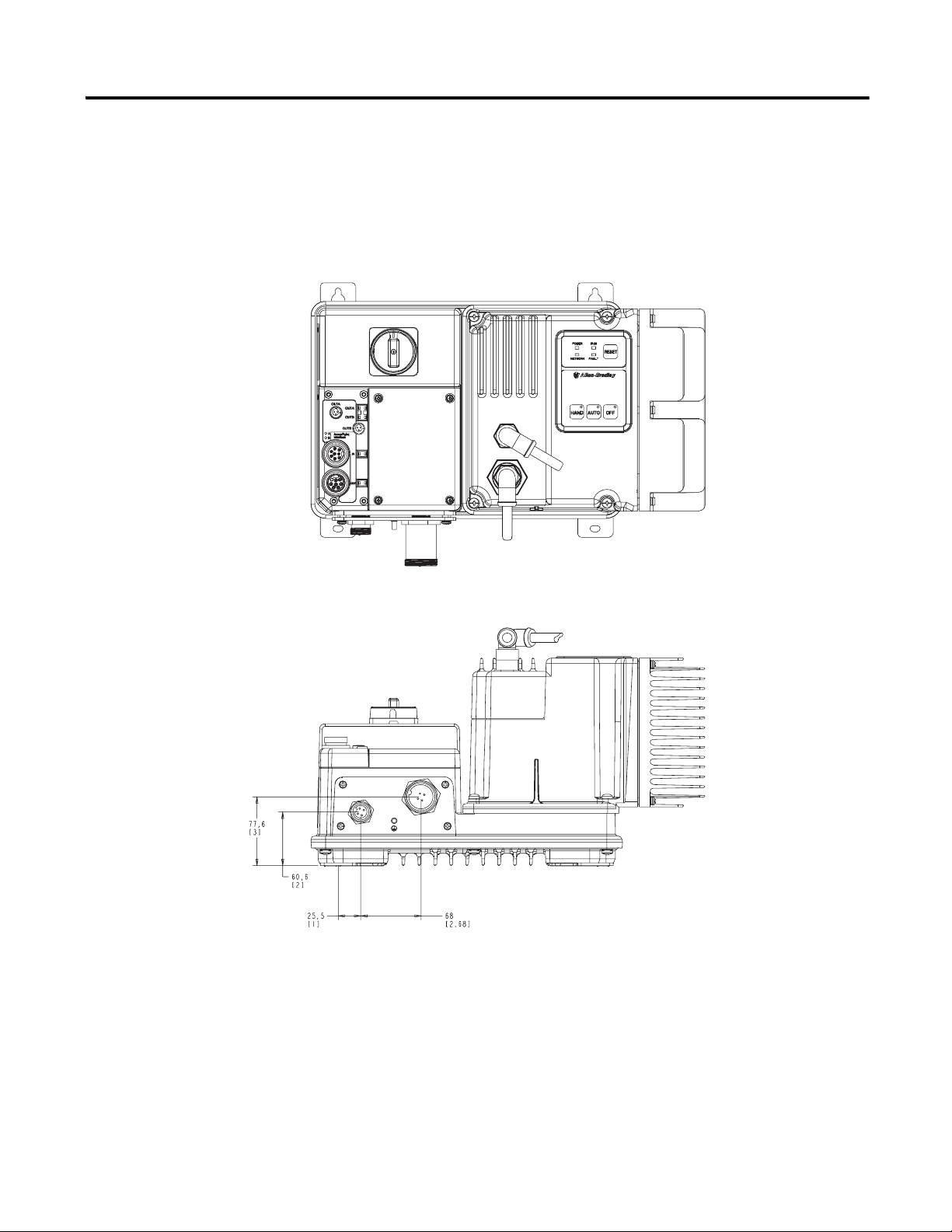
Installation The ArmorStart Distributed Motor Controller is convection cooled.
Operating temperature must be kept between –20…40°C (–4…104°F).
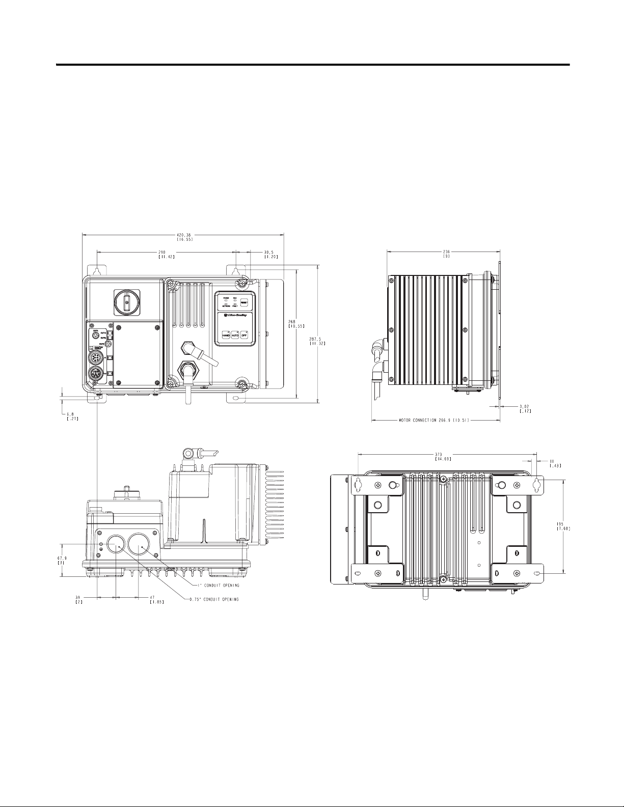
Dimensions Dimensions are shown in millimeters (inches). Dimensions are not intended
to be used for manufacturing purposes. All dimensions are subject to
change.
Figure 1 Dimensions for 1 Hp and below @ 230V AC, 2 Hp and below @ 460V AC,
and 2 Hp and below @ 575V AC, IP67/NEMA Type 4 with
Conduit Entrance
Publication 284A-QS001C-EN-P - July 2006
Page 4
4
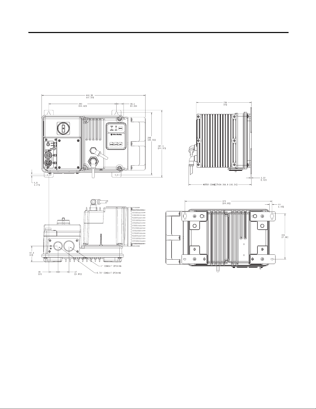
Dimensions are shown in millimeters (inches). Dimensions are not intended
to be used for manufacturing purposes. All dimensions are subject to
change.
Figure 2 Dimensions for 2 Hp @ 230V AC, 3 Hp and above @ 460V AC, and 3 Hp and
above @ 575V AC, IP67/NEMA Type 4 with Conduit Entrance
Publication 284A-QS001C-EN-P - July 2006
Page 5
5
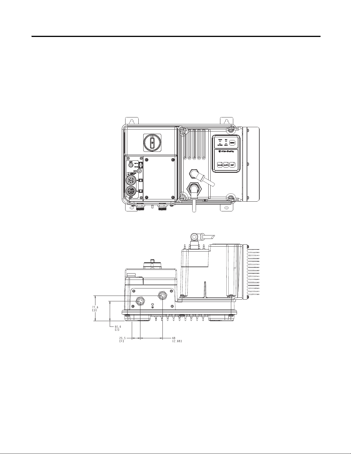
ArmorStart device with a 10 A short circuit protection rating
Dimensions are shown in millimeters (inches). Dimensions are not intended
to be used for manufacturing purposes. All dimensions are subject to
change.
Figure 3 Dimensions for 1 Hp and below @ 230V AC, 2 Hp and below @ 460V AC,
and 2 Hp and below @ 575V AC, IP67/NEMA Type 4 with
ArmorConnect™ Connectivity
Publication 284A-QS001C-EN-P - July 2006
Page 6
6
ArmorStart device with a 25 A short circuit protection rating
Dimensions are shown in millimeters (inches). Dimensions are not intended
to be used for manufacturing purposes. All dimensions are subject to
change.
Figure 4 Dimensions for 2 Hp @ 230V AC, 3 Hp and above @ 460V AC, and 3 Hp and
above @ 575V AC, IP67/NEMA Type 4 with ArmorConnect Connectivity
Publication 284A-QS001C-EN-P - July 2006
Page 7
Wiring Power, Control, Safety Monitor Inputs, and Ground Wiring
Primaries
Secondaries
Table 1 provides the power, control, safety monitor inputs, ground wire
capacity and the tightening torque requirements. The power, control,
ground, and safety monitor terminals will accept a maximum of two wires
per terminal.
Table 1 Power, Control, Safety Monitor Inputs, Ground Wire Size, and Torque
Specifications
Terminals Wire Size Torque Wire Strip Length
7
Primary Terminal:
10.6…21.6 lb.-in.
(1.2…2.4 N•m)
Secondary Terminal:
5.3…7.3 lb.-in
(0.6…0.8 N•m)
5.0…5.6 lb.-in
(0.6 N•m)
0.35 in. (9 mm)
0.35 in. (9 mm)
Power
and
Ground
Control and Safety
Monitor Inputs
Primary/Secondary
Terminal:
1.0…4.0 mm
(#18 …#10 AWG)
2
0.34mm
…4.0 mm2
(#22…#10 AWG)
2
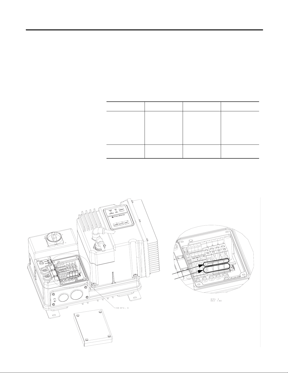
Terminal Designations As shown in Figure 5, the ArmorStart Distributed Motor Controller contains
terminals for power, control, safety monitor inputs and ground wiring.
Access can be gained by removing the terminal access cover plate.
Figure 5 ArmorStart Power, Control, and Safety Monitor Terminals
Publication 284A-QS001C-EN-P - July 2006
Page 8

8
Table 2 Power, Control, and Ground Terminal Designations
Terminal Designations No. of Poles Description
SM1 ➊ 2 Safety Monitor Input
SM2 ➊ 2 Safety Monitor Input
A1 (+) 2 Control Power Input
A2 (-) 2 Control Power Common
PE 2 Ground
1/L1 2 Line Power Phase A
3/L3 2 Line Power Phase B
5/L5 2 Line Power Phase C
➊ Only available with the Safety Monitor option.
Publication 284A-QS001C-EN-P - July 2006
Page 9
ArmorConnect Power Media Description
RESET
Bulletin 280/281
ArmorStart
ArmorPoint
Bulletin 284
ArmorStart
Ethernet
PLC
Bulletin 1492FB
Branch Circuit
Protective Device
Enclosure
Bulletin 1606
Bulletin 1606
Bulletin 800F
Emergency Stop
Pushbutton
4
Computer
Terminal
The ArmorStart Power Media offers both three-phase and control power
cable system of cordsets, patchcords, receptacles, tees, reducers and
accessories to be utilized with the ArmorStart Distributed Motor Controller.
These cable system components allow quick connection of ArmorStart
Distributed Motor Controllers and reduce installation time. They provide
for repeatable, reliable connection of the three-phase and control power to
the ArmorStart Distributed Motor Controller and motor by providing a plug
and play environment that also avoids system mis-wiring. When specifying
power media for use with the ArmorStart Distributed Motor Controllers
(Bulletins 280, 281, 283, and 284) use only the Bulletin 280
ArmorConnect™ power media.
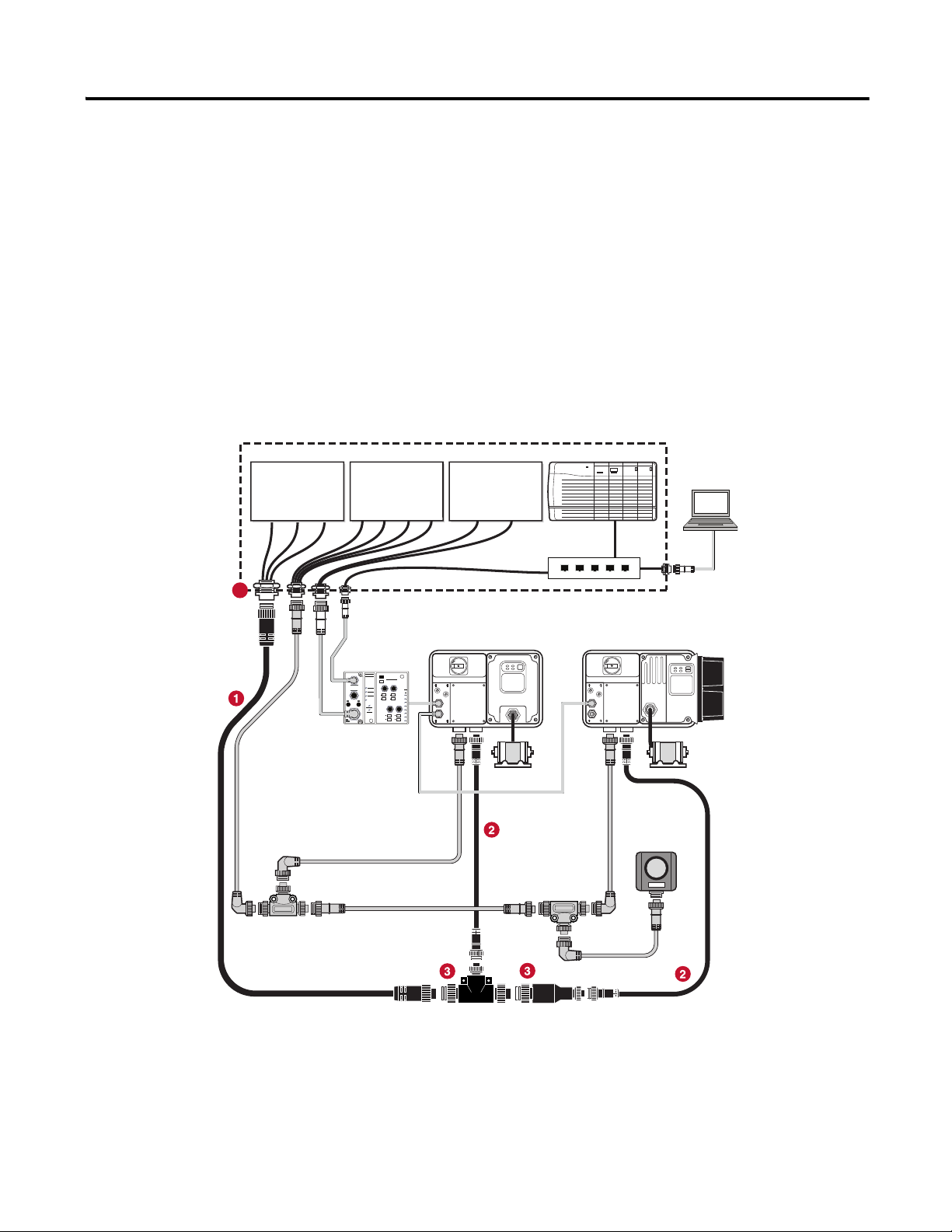
Figure 6 Three-Phase Power System Overview
9
➊ Three-Phase Power Trunk- PatchCord cable with integral female or male connector on each end. (Example Part Number: 280-PWR35A-M*)
➋ Three-Phase Drop Cable- PatchCord cable with integral female or male connector on each end. (Example Part Number: 280-PWR22A-M*)
➌ Three-Phase Power Tees and Reducer -
Tee connects to a single drop line to trunk with quick change connectors – Part Number: 280-T35
Reducing Tee connects to a single drop line (Mini) to trunk (Quick change) connector – Part Number: 280-RT35
Reducer connects from quick change male connector to mini female connector– Part Number: 280-RA35
➍ Three-Phase Power Receptacles -
Female receptacles are a panel mount connector with flying leads – Part Number: 280-M35F-M1
Publication 284A-QS001C-EN-P - July 2006
Page 10
10
RESET
Bulletin 280/281
ArmorStart
ArmorPoint
Bulletin 284
ArmorStart
Ethernet
PLC
Bulletin 1492FB
Branch Circuit
Protective Device
Enclosure
Bulletin 1606
Bulletin 1606
Bulletin 800F
Emergency Stop
Pushbutton
8
6
6
6
6
7
7
Computer
Terminal
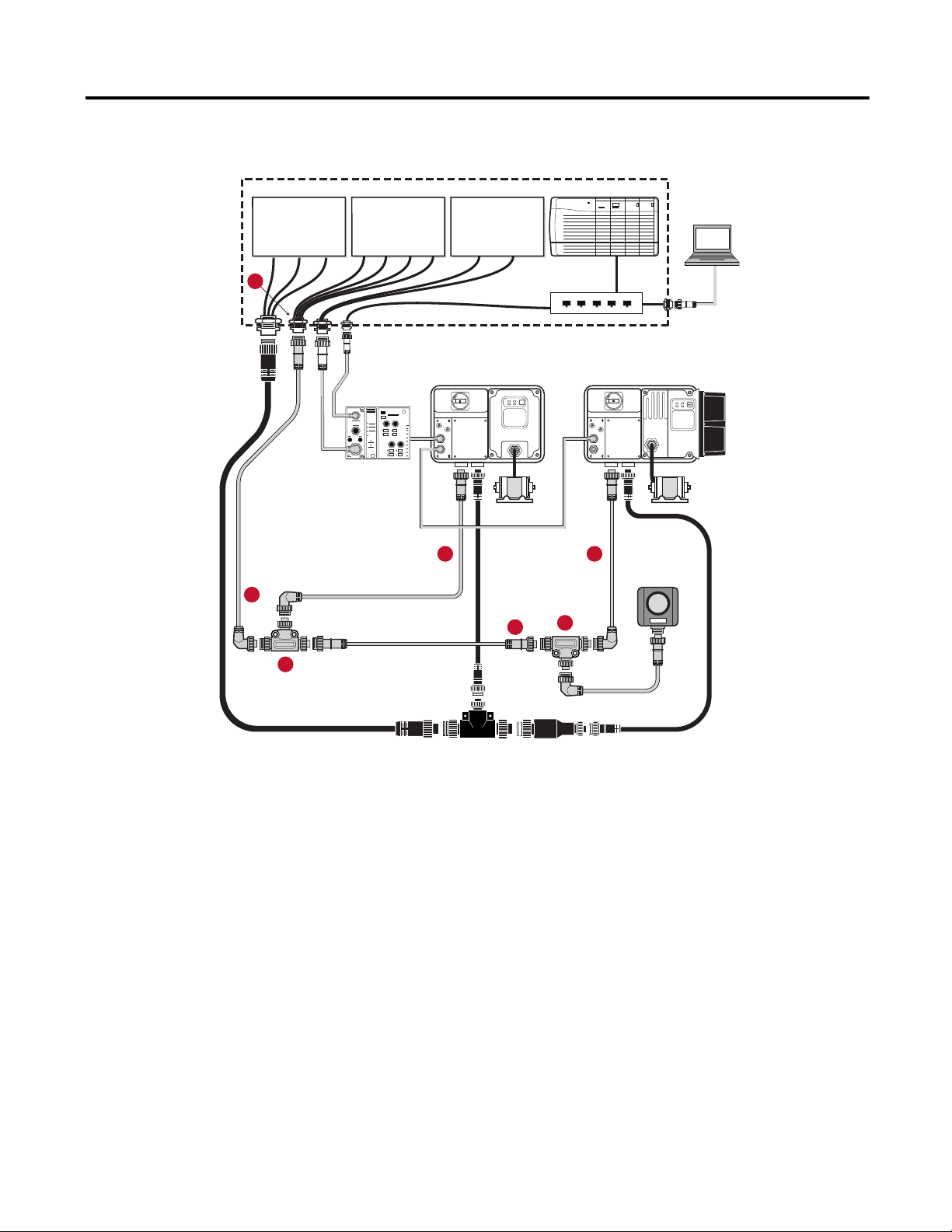
Figure 7 Control Power Media System Overview
➏ Control Power Media Patchcords - PatchCord cable with integral female or male connector on each end
Example Part Number: 889N-F65GFNM-*
➐ Control Power Tees - The E-stop In Tee (Part Number: 898N-653ES-NKF) is used to connect to the Bulletin 800F On-Machine E-Stop station using a
control power media patchcord. The E-stop Out tee (Part Number: 898N-653ST-NKF) is used with cordset or patchcord to connect to the ArmorStart
Distributed Motor Controller.
➑ Control Power Receptacles - Female receptacles are a panel mount connector with flying leads –
Part Number: 888N-D65AF1-*
Publication 284A-QS001C-EN-P - July 2006
Page 11
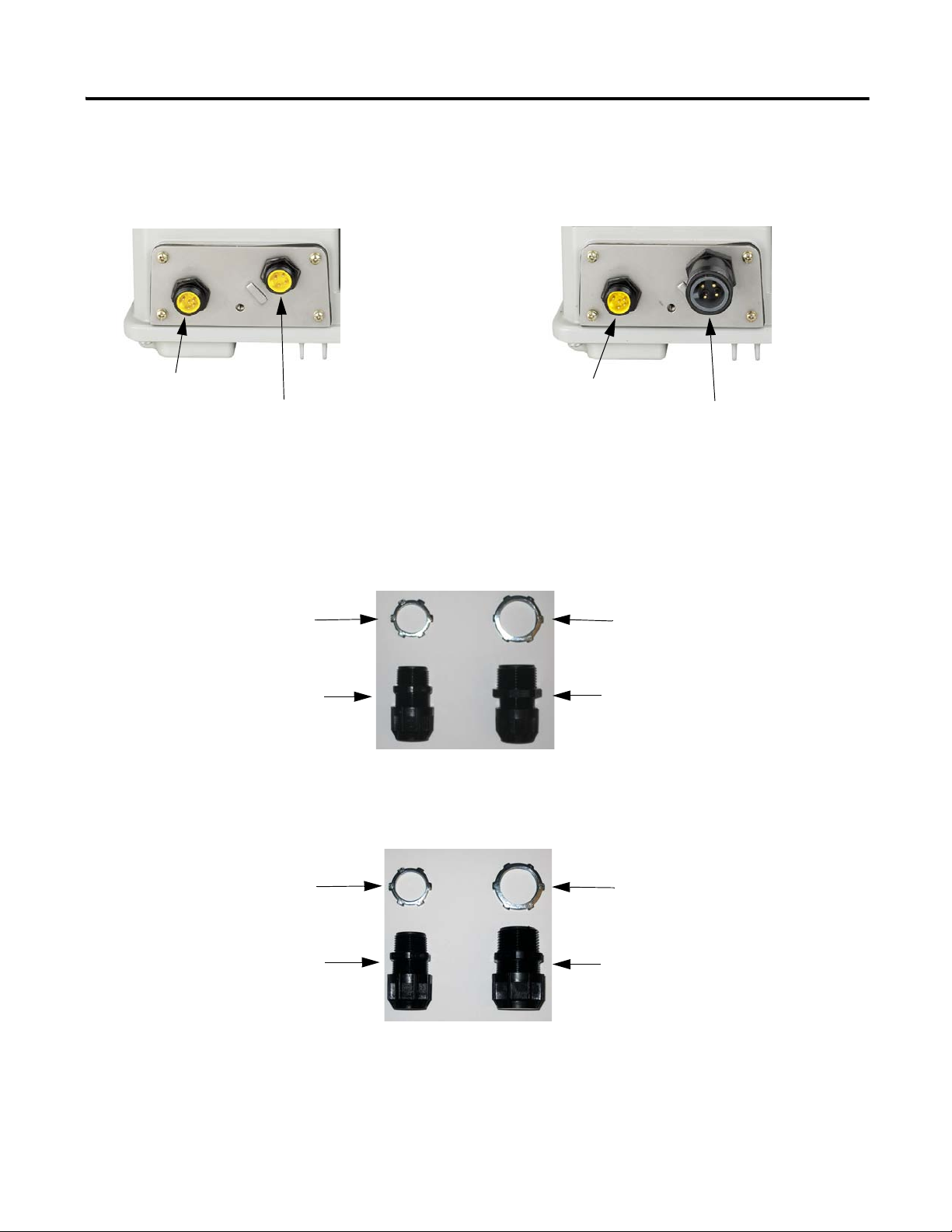
ArmorStart with ArmorConnect Connectivity
Control Power Receptacle
Three-Phase Power Receptacle
Control Power Receptacle
Three-Phase Power Receptacle
ArmorStart devices with 10 A short
circuit protection rating
ArmorStart devices with 25 A short
circuit protection rating
3/4 in. Lock Nut 1 in. Lock Nut
Thomas & Betts Cord Grip
Part Number: 2931NM
3/4 in. Stain Relief Cord Connector
Cable Range: 0.31…0.56 in.
Used with Control Power Media
Cordset - Example Part Number:
889N-M65GF-M2
Thomas & Betts Cord Grip
Part Number: 2940NM
1 in. Stain Relief Cord Connector
Cable Range: 0.31…0.56 in.
Used with Three-Phase Power
Media Cordset - Example Part
Number: 280-PWR22G-M1
Cord Grips for ArmorStart Devices with 10 A short circuit protection rating
3/4 in. Lock Nut 1 in. Lock Nut
Thomas & Betts Cord Grip
Part Number: 2931NM
3/4 in. Stain Relief Cord Connector
Cable Range: 0.31…0.56 in.
Used with Control Power Media
Cordset - Example Part Number:
889N-M65GF-M2
Thomas & Betts Cord Grip
Part Number: 2942NM
1 in. Stain Relief Cord Connector
Cable Range: 0.70…0.95 in.
Used with Three-Phase Power
Media Cordset - Example Part
Number: 280-PWR35G-M1
Cord Grips for ArmorStart Devices with 25 A short circuit protection rating
Installing ArmorConnect Power Media using Cord Grips
11
Publication 284A-QS001C-EN-P - July 2006
Page 12
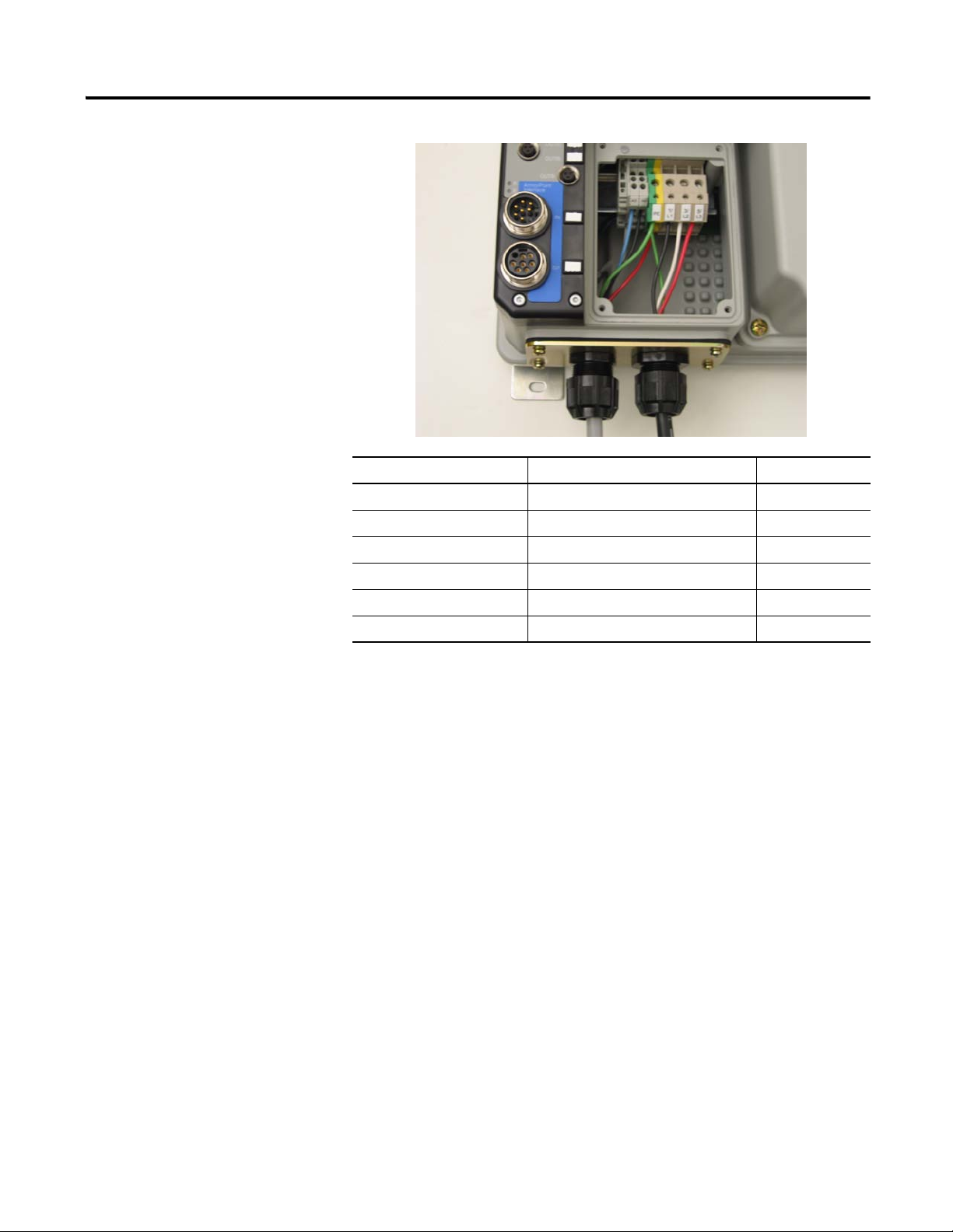
12
Terminal Designations Description Color Code
A1 (+) Control Power Input Blue
A2 (-) Control Power Common Black
PE Ground Green/Yellow
1/L1 Line Power - Phase A Black
2/L2 Line Power - Phase B White
3/L3 Line Power - Phase C Red
ArmorConnect Cable Ratings
The ArmorConnect Power Media cables are rated per UL Type TC
600V 90 °C Dry 75 °C Wet, Exposed Run (ER) or MTW 600V 90 °C or
STOOW 105 °C 600V - CSA STOOW 600V FT2. For additional
information regarding ArmorConnect Power Media see the ArmorStart
User Manual.
Branch Circuit Protection Requirements for ArmorConnect™
Three-Phase Power Media
When using ArmorConnect Three-Phase Power Media, only fuses can be
used for the motor branch circuit protective device, for the group motor
installations. The recommended fuse types are the following: Class CC, T,
or J type fuses. For additional information, see the ArmorStart User
Manual.
Publication 284A-QS001C-EN-P - July 2006
Page 13

13
Group Motor Installations for USA and Canada Markets
The ArmorStart Distributed Motor controllers are listed for use with each
other in group installations per NFPA 79, Electrical Standard for Industrial
Machinery. When applied according to the group motor installation
requirements, two or more motors, of any rating or controller type, are
permitted on a single branch circuit. Group Motor Installation has been
successfully used for many years in the USA and Canada.
Wiring and Workmanship Guidelines
In addition to conduit and seal-tite raceway, it is acceptable to utilize cable
that is dual rated Tray Cable, Type TC-ER and Cord, STOOW, for power
and control wiring on ArmorStart installations. In the USA and Canada
installations, the following guidance is outlined by the NEC and NFPA 79.
In industrial establishments where the conditions of maintenance and
supervision ensure that only qualified persons service the installation, and
where the exposed cable is continuously supported and protected against
physical damage using mechanical protection, such as struts, angles, or
channels, Type TC tray cable that complies with the crush and impact
requirements of Type MC (Metal Clad) cable and is identified for such use
with the marking Type TC-ER (Exposed Run)* shall be permitted between
a cable tray and the utilization equipment or device as open wiring. The
cable shall be secured at intervals not exceeding 1.8 m (6 ft) and installed in
a “good workman-like” manner. Equipment grounding for the utilization
equipment shall be provided by an equipment grounding conductor within
the cable.
*Historically cable meeting these crush and impact requirements were
designated and marked “Open Wiring”. Cable so marked is equivalent to the
present Type TC-ER and can be used.
While the ArmorStart is intended for installation in factory floor
environments of industrial establishments, the following must be taken into
consideration when locating the ArmorStart in the application: Cables,
including those for control voltage including 24V DC and communications,
are not to be exposed to an operator or building traffic on a continuous
basis. Location of the ArmorStart to minimize exposure to continual traffic
is recommended. If location to minimize traffic flow is unavoidable, other
barriers to minimize inadvertent exposure to the cabling should be
considered. Routing cables should be done in such a manner to minimize
inadvertent exposure and/or damage.
Additionally, if conduit or other raceways are not used, it is recommended
that strain relief fittings be utilized when installing the cables for the control
and power wiring through the conduit openings.
The working space around the ArmorStart may be minimized as the
ArmorStart does not require examination, adjustment, servicing or
maintenance while energized. In lieu of this service, the ArmorStart is
Publication 284A-QS001C-EN-P - July 2006
Page 14

14
ATTENTION
!
meant to be unplugged and replaced after proper lockout/tag-out procedures
have been employed.
Since the ArmorStart is available with a factory installed HOA keypad
option this may require the ArmorStart to be selected and installed as
follows if the application requires frequent use of the hand operated
interface by the equipment operator:
1. They are not less than 0.6 m (2 ft) above the servicing level and are
within easy reach of the normal working position of the operator.
2. The operator is not placed in a hazardous situation when operating
them.
3. The possibility of inadvertent operation is minimized.
If the operated interface is used in industrial establishments where the
conditions of maintenance and supervision ensure that only qualified
persons operate and service the ArmorStart's operator interface, and the
installation is located so that inadvertent operation is minimized then other
installation locations with acceptable access can be provided.
AC Supply Considerations
Ungrounded Distribution Systems
The Bulletin 284 contains protective MOVs that are
referenced to ground. These devices should be
disconnected if the Bulletin 284 is installed on an
ungrounded distribution system.
Disconnecting MOVS
To prevent drive damage, the MOVs connected to ground shall be
disconnected if the drive is installed on an ungrounded distribution system
where the line-to-ground voltages on any phase could exceed 125% of the
nominal line-to-line voltage. To disconnect these devices, remove the
jumper shown in Figure 9, Jumper Removal.
1. Before installing the Bulletin 284, loosen four mounting screws.
2. Unplug control module from the base unit by pulling forward.
Publication 284A-QS001C-EN-P - July 2006
Page 15
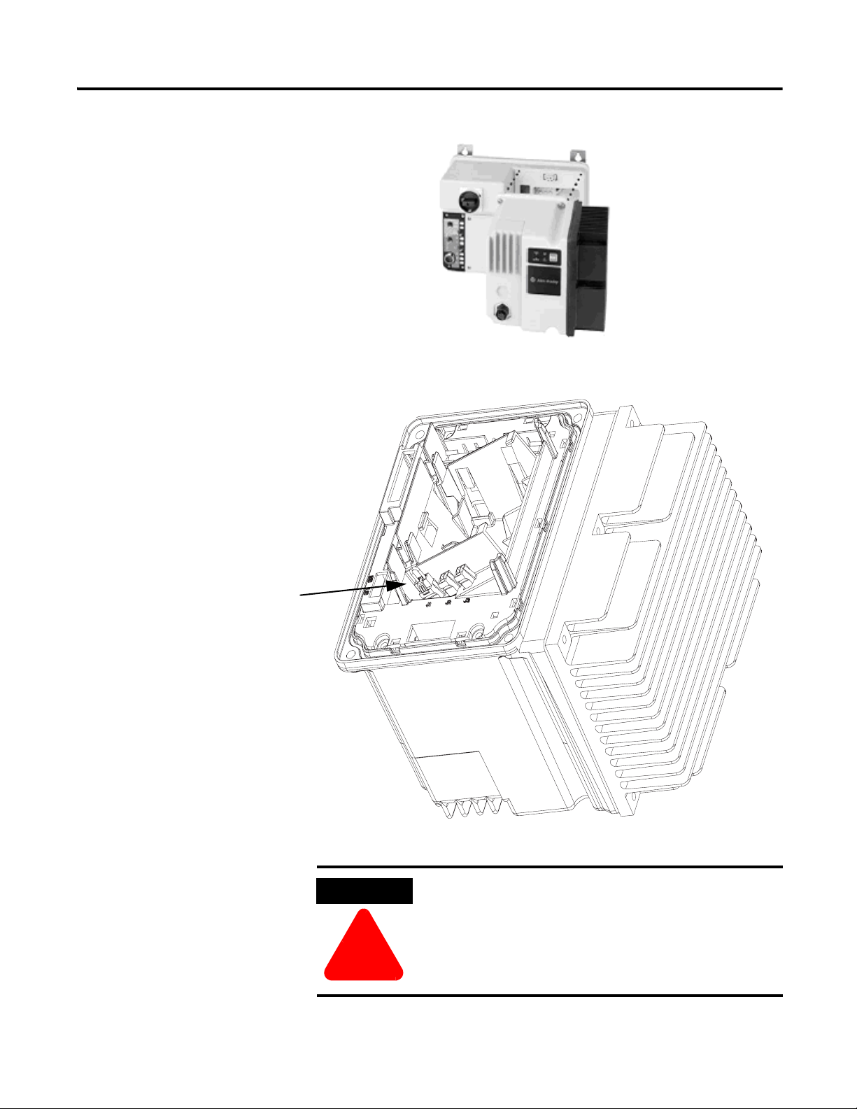
Figure 8 Removal of Control Module
Remove Jumper
ATTENTION
!
Figure 9 Jumper Removal
15
Do not remove this jumper if the unit is equipped with an
EMI filter installed.
Publication 284A-QS001C-EN-P - July 2006
Page 16

16
LED Status Indication The LED Status Indication provides 4 status LEDs and a Reset button. The
LEDs provide status indication for the following:
• POWER LED
The LED is illuminated solid green when control power is present and
with the proper polarity
•RUN LED
This LED is illuminated solid green when a start command and control
power are present
• NETWORK LED
This bi-color (red/green) LED indicates the status of the
communication link
• FAULT LED
Indicates Controller Fault (trip) condition
The “Reset Button” as a local trip reset.
Figure 10 LED Status Indication and Reset
ArmorStart with ArmorPoint ArmorStart for the ArmorPoint Backplane
The Bulletin 284A ArmorStart Distributed Motor Controller allows
connectivity to the ArmorPoint backplane. The ArmorPoint I/O system can
communicate using DeviceNet™, ControlNet™, or EtherNet
communication protocols. In addition to the other network communication
protocols; the ArmorPoint Distributed I/O products allow the I/O capability
to be expanded beyond the standard two outputs. Two dual-key relay output
connectors are provided standard. The outputs are sourced from control
voltage power (A1, A2). LED status indication is also provided, as standard
with the ArmorPoint. When using ArmorPoint, a maximum of two
ArmorStart Distributed Motor Controllers can be connected to the
ArmorPoint Distributed I/O products.
ArmorStart to ArmorPoint Connectivity
Figure 11 Connectivity Diagram for one ArmorStart Distributed Motor Controller
Publication 284A-QS001C-EN-P - July 2006
Page 17

17
ATTENTION
!
When connecting to the Bulletin 1738 ArmorPoint Distributed I/O product,
a network adapter and at least one ArmorPoint Digital Output, Digital Input,
Analog, AC and Relay product, or Specialty product must be selected. The
ArmorPoint Distributed I/O product can accommodate up to 63 modules per
network node. The cable that connects the ArmorPoint Distributed I/O to
the ArmorStart Distributed Motor Controller is the Bulletin 280A-EXT1.
The 280A-EXT1 includes an ArmorPoint bus extension cable and a
network terminating resistor. The network terminating resistor must be
connected to the “ArmorPoint Interface Out” connector.
Figure 12 Connectivity Diagram for two ArmorStart Distributed Motor Controllers
If an additional ArmorStart Distributed Motor Controller is to be connected,
the Bulletin 280A-EXTCABLE will be required. A maximum of two
ArmorStart Distributed Motor Controllers can be connected to the Bulletin
1738 Distributed I/O. The Bulletin 280A-EXTCABLE is connected from
the “ArmorPoint Interface Out” on the first unit, to the “ArmorPoint
Interface In” on the second unit. The network terminating resistor is
connected to the “ArmorPoint Interface Out” on the second unit.
ArmorPoint Backplane Commissioning:
Three-phase power must be applied to the Bulletin 284
Distributed Motor Controller to gain access to drive
parameters.
Establishing a Backplane Node Address
Backplane node addresses are established automatically by the ArmorPoint
system on power up. Node addresses for the backplane modules are
allocated from left to right, starting at address 1.
Note: The rotary address switches are ignored on the starter module when
using the ArmorPoint backplane.
Note: When using RSNetWorx for DeviceNet with the 284A ArmorStart
Distributed Motor Controllers, DO NOT use the node
commissioning outlined in Chapter 5 of the User Manual.
Publication 284A-QS001C-EN-P - July 2006
Page 18

18
Details on Using the “ArmorStart Ladder Logic Configurator”
The ArmorStart Ladder Logic Configurator is a ladder logic routine (File
Name: ArmorStart_Configurator.ACD) designed so that under program
control, the entire product family of the ArmorStart Distributed Motor
Controllers can be configured easily from a Logix based controller. The
family of ArmorStart Distributed Motor Controllers includes the following
Bulletin Numbers: 280A, 281A, 283A and 284A. The ArmorStart
Distributed Motor Controllers can be networked over ControlNet or
EtherNetIP, when on the appropriate ArmorPoint backplane. The ladder
logic file is designed to be merged into an existing ladder logic file or it can
be used as the basic program and other logic can be added to it. This
document assumes that the reader has an average knowledge of the use of
RSLogix™5000 and Logix based controllers. Device configuration is done
inside the Controller tag editor under the Monitor Tags tab.
Note: The ArmorStart Ladder Logic Configurator (File Name:
ArmorStart_Configurator.ACD) is provided on the CD shipped with
every ArmorStart product with the ArmorPoint Communications
protocol.
Publication 284A-QS001C-EN-P - July 2006
Page 19

19
Theory of Operation
It is possible to connect an ArmorStart product to the Point I/O based subnet
of the ArmorPoint I/O system. This allows the ArmorStart to be connected
to EtherNetIP and ControlNet, along with the original DeviceNet. The
easiest way to program these ArmorStarts is to use RSNetWorx for
DeviceNet software, bridging through the appropriate network. This
ladder logic has been developed as an alternate method of configuration.
Once the appropriate device configuration is done to a User Defined
Structure in the ladder logic file, a bit will need to be turned on in the logic
to trigger a system wide read of the system. This system wide read, goes out
and reads certain attributes of every parameter of every ArmorStart in the
system and stores the information into a large data array. The first attribute
is a flag word that tells the ladder logic if the parameter is read only. If the
read only bit is set, then the ladder logic will skip the additional attribute
reads and will go to the next parameter. If the parameter is writable, then the
logic will read the size, min. allowed value, max. allowed value, the
parameter name, help string and the raw data of each parameter. These
attributes are stored in the data array for use later when the configuration is
written to each ArmorStart. The logic requires that a system wide read
function be completed prior to a system wide write function being
requested.
Note: A system wide read function should be done anytime that a new
ArmorStart is added to the system or an ArmorStart is updated with
a more recent version. This assures that the data array in the logic
matches the total system.
Once a system wide read is done, the raw data of the individual parameters
in the data array can be modified and a system wide write function activated
from a bit in the ladder logic. Only parameters that changed will be written
to the ArmorStart devices, and after a write is done the parameter is read
back and stored in the data array for comparison. If the write and reread
value do not match, an Error Report is generated.
If an error occurs for any reason, during a system wide read or write, an
error report will be logged, containing the device and parameter it occurred
on. Also the status and extended status of the message block is logged in
case the error originated there.
Publication 284A-QS001C-EN-P - July 2006
Page 20

20
I/O Tree Overview
In order to transfer I/O information, the ArmorStart needs to be added to the
I/O tree of the Logix processor. The details of doing this are outside of the
scope of these instructions, but screen captures of the completed
configuration are included below for reference. The configuration below
shows the EtherNetIP card in the Logix chassis slot 1. The 1738-AENT
module is always located at slot zero in the subnet and the ArmorStart
device is located in slot 2 on the subnet. These slots are circled below for
you reference.
Figure 13 Logix Processor I/O Tree
The only configuration that the user needs to be concerned with for the
ArmorPoint communication adapter is either the EtherNet IP address or the
ControlNet node address.
Since there currently is no profile for an ArmorStart device in the I\O Tree,
the 1738-MODULE profile needs to be used as a generic profile. The
standard configuration for an ArmorStart 284A, using this profile is shown
below.
Figure 14 ArmorStart Configuration using 1738-MODULE Profile
Publication 284A-QS001C-EN-P - July 2006
Page 21

21
Logic Configuration Details
Inside the Configurator file is a large User Defined structure called
Armor_Start_System, which contains all of the data for both the
configuration of the routine, and also storage space for all of the ArmorStart
parameters. With 20 devices, the total memory needed to hold this structure
in the Logix controller is 195K bytes. The diagram below shows the upper
part of the structure and 3 important elements.
Figure 15 Configurator File — Armor_Start_System
Armor_Start_System.Max_Devices defaults to 20; because the total
number of devices that the structure is designed to hold initially, is 20. This
amount can be easily changed, but doing so will also necessitate a
change to the size of the System Array structure to match exactly.
Note: The Logix memory that contains the structure will also change size
proportionally.
Shown below is the array size that will also need to be changed to match the
Armor_Start_System.Max_Devices value.
Figure 16 System Array Size
Armor_Start_System.Max_Parameters defaults to 262, because the
maximum number of parameters in any existing ArmorStart product is 262
or less. This amount can be easily be changed, and doing so will also
proportionally change the size of the System Array structure and the Logix
memory that holds it. Shown below is the array size that will also need to
be changed to be 1 greater than the
Armor_Start_System.Max_Parameters value. This is because the
parameters are stored by parameter number, and since there is no parameter
0, that storage location is unused.
Publication 284A-QS001C-EN-P - July 2006
Page 22

22
Figure 17 Array Size Parameter
Armor_Start_System.Num_Devices defaults to zero and is defined as the
total number of ArmorStart products connected to the control system that
need to be configured. It is important that this value be set before the
configuration routine is executed.
It is to the users best advantage to trim the structures down to the minimum
values that match their system because this will save a considerable amount
of Logix processor memory. However, some room should be left in the
structures to handle any future additions of ArmorStart devices to the
system.
Adding Devices to the Configuration Structure
Once the three major System level parameters are entered, it is up to the
user to enter in, each of the ArmorStart devices configuration information.
These parameters are defined by the slot in the Logix chassis where the
EtherNetIP or ControlNet communication card resides. The next parameter
is the EtherNetIP IP or ControlNet node address of the 1738 communication
adapter containing the ArmorStart. Lastly, the slot number on the
ArmorPoint subnet where the ArmorStart is connected also needs to be
entered. An optional parameter is a string that can be entered with a
description of the function of the ArmorStart device. Each device will be
configured by entering its data into a different block of the
Armor_Start_System.Device[] array.
The Following shows the configuration for a communication card in the
Logix chassis 2, AENT IP address 192.168.1.10 and Point I/O slot 3. The
logic determines whether the network is EtherNetIP or ControlNet
depending on whether the ENET_IP_Addr field is blank or the
CNET_Address is zero. One of these two fields must be filled out for the
logic to work correctly. The Armor_Descriptor field is optional and is used
to more easily identify the ArmorStart as to its function in the system.
Publication 284A-QS001C-EN-P - July 2006
Page 23

23
Figure 18 Communication Card Configuration
Note: To easily edit an ASCII string, click on the string value field and a
small icon with three dots appears.
Figure 19 String Browser Box
Click on the three dots icon and a String Browser box appears. Modify the
text to what is desired and click on Apply, then click on OK. This works for
ALL strings throughout the entire data array.
Figure 20 String Browser Box
Modifying Parameter Data for an ArmorStart
The last configuration that will need to be done eventually, is the writing of
a parameter configuration change for an ArmorStart. This is done by first
equating a particular ArmorStart to a device number in the data array.
Again, this device number is determined by the Logix slot of the
communication card, ETherNetIP or CNet address of the communication
adapter and subnet slot of ArmorStart. The optional, Armor_Descriptor
field is extremely handy for doing a functional lookup of the device number.
Once the device number is determined, the parameter number to be
modified, must be obtained. The best way to do this, is to go to the
ArmorStart user manual and get the parameter number of the value to be
Publication 284A-QS001C-EN-P - July 2006
Page 24

24
modified. The parameter numbers all start with 1 and are numbered
sequentially to the last parameter number. The user manual is important
because it will thoroughly describe each parameter, for example, whether or
not a parameter is writable and what the parameter limits/interpretation are.
Once the device and parameter number is obtained, the next step is to
modify the configuration data for that parameter. The following screen
capture shows the data array and particularly, the parameter 8 for Device 0.
Figure 21 Data Array
The value to be modified is the .data element of the structure. For reference,
the Min_value, Max_value, and Name_String for the parameter is also in
the structure, so that the user knows what the minimum and maximum
allowable values are for the data. It is important to realize that the data is in
a raw format. In other words, this data could be considered a Boolean, a bit
mask, an ASCII string, an integer, a byte, etc., depending on the definition
of the parameter in the ArmorStart. Also, there could be an implied decimal
point, scaling, and different units involved. It is important that the user
fully understand and verify the raw data value being modified with the
user manual, so that it is correctly interpreted by the ArmorStart or
undesired operation in the ArmorStart may occur.
Once the data is written, during a System Wide Write function, the ladder
logic will read it back and put into the .Last_Read_Value of the structure.
This will be a handy visual verification that the data was written correctly.
Publication 284A-QS001C-EN-P - July 2006
Page 25

25
Triggering a System Wide Read
Once the system configuration has been done, a System Wide Read must be
initiated. The logic to trigger both a System Wide Read and Write is
contained in a subroutine called Handle_All_Armor. The rungs are shown
below for reference.
Figure 22 Handle_All_Armor Rungs
To trigger the system wide read, the contact Read_All_Condition_Here
needs to be energized in the ladder logic. This can be done through
additional logic or simply by energizing the bit, on-line, in the
RSLogix5000 software, Controller Tag monitor screen. The
Read_All_Condition_Here is handled as a one shot inside the logic, but
should be de-energized at a later time. This is so a system wide read is not
triggered after every Logix power cycle or for each transition from Program
to RUN mode. When the read finishes successfully, the
Read_All_System_Done_Flag bit energizes in the logic. However, if an
error occurs during the read, the Read_All_System_Error_Flag bit
energizes and the error will be logged into the structure called
Error_Report.
Triggering a System Wide Write
Once a successful System Wide Read has been initiated and the
Read_All_System_Done_Flag bit is energized, a System Wide Write can
be triggered. To trigger the system wide write, the contact
Write_All_Condition_Here needs to be energized in the ladder logic. This
can be done through additional logic or simply by energizing the bit on-line,
in the RSLogix5000 software, Controller Tag monitor screen. The
Write_All_Condition_Here is handled as a one shot inside the logic, but
should be de-energized at a later time. This is so a System Wide Write is not
triggered after every Logix power cycle or for each transition from Program
to RUN mode. When the write finishes successfully, the
Write_All_System_Done_Flag bit energizes in the logic. If an error occurs
during the write, the Write_All_System_Error_Flag bit energizes and the
error will be logged into the structure called Error_Report.
Publication 284A-QS001C-EN-P - July 2006
Page 26
26
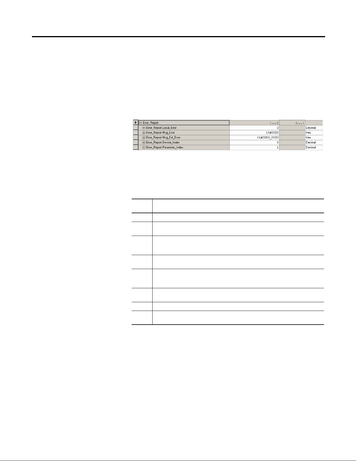
Interpreting the Error Report
If an error occurs during the operation of the ladder logic, either the
Write_All_System_Error_Flag or Read_All_System_Error_Flag bits will
energize depending on which function was being triggered. Information will
be logged inside the data structure Error_Report, that will aid in
troubleshooting the problem. The format of this structure is shown below.
Figure 23 Error Report
The first element of this structure is .Local_Error and will contain a
number corresponding to an error interpretation. The error numbers are
described in the next table.
Table 3 Error Definitions
Error
No.
0 Success. Function completed successfully.
1 Read Number Parameter Error. Num_Devices element in the configuration is either 0 or
greater than the Max_Devices element.
2 Read Message Block Error. The Message block doing the data reads returned back an
error. Look at the Msg_Error and Msg_Ext_Error fields for the errors reported by the
message.
3 Write Data out of Limits. The value of the data to be written is either less than the
Min_value or greater than the Max_value.
4 Write Message Block Error. The Message block doing the data writes returned back an
error. Look at the Msg_Error and Msg_Ext_Error fields for the errors reported by the
message.
5 Write Disallowed. The System Wide Write attempted without a successful System Wide
Read done first.
6 Data Write Error. The data read back after a parameter write, does not match.
7 Number of Parameters Error. The number of parameters read from an ArmorStart is
greater than the Max_Devices element in the structure.
Error Description
Publication 284A-QS001C-EN-P - July 2006
Page 27

Bulletin 284 Pararmeters
IMPORTANT
Table 4 Basic Program Group for Sensorless Vector Performance
27
Parameter
Number
131 ➊ Motor NP Volts 1 VAC
132 ➊ Motor NP Hz 1 Hz 10/240 Hz 60 Hz
133
134 Minimum Freq. 0.1 Hz 0.0/240 Hz 0.0 Hz
135 ➊
136 ➊ Start Source
137 Stop Mode
138
139 Accel Time 1 0.1 Secs 0.0/600.0 Secs 10.0 Secs
140 Decel Time 1 0.1 Secs 0.0/600.0 Secs 10.0 Secs
141 ➊
Parameter
Description
Motor OL
Current
Maximum
Freq.
Speed
Reference
Reset to
Default
Display/
Options
0.1 A
0.1 Hz 0.0/240 Hz 60 Hz
0 = Keypad ➋
1 = 3-Wire ➋
2 = 2-Wire
3 = 2-W Lvl Sens
4 = 2-W Hi Speed
5 = Comm Port
0 = Ramp, CF
1 = Coast, CF
2 = DC Brake, CF
3 = DCBrkAuto, CF
4 = Ramp
5 = Coast
6 = DC Brake
7 = DC BrakeAuto
0 = Drive Pot ➋
1 = InternalFreq
2 = 0…10V Input ➋
3 = 4…20 mA Input ➋
4 = Preset Freq
5 = Comm Port
0 = Ready/Idle
1 = FactoryRset
Min./
Max.
20/Drive Rated
Volts
0.0/(Drive Rated
Amps x 2)
0/5 5
0/7 0
0/5 5
0/1 0
Defaults
Settings
Based on
Based on
Driving
Rating
Driving
Rating
➊ Stop drive before changing this parameter.
➋ See Important below:
These drive parameters options will cause the
Bulletin 284 ArmorStart Distributed Motor Controller to
become disabled.
Publication 284A-QS001C-EN-P - July 2006
Page 28

28
IMPORTANT
Table 5 Basic Program Group for Sensorless Vector Control
Parameter
Number
131 ➊ Motor NP Volts 1 VAC
132 ➊ Motor NP Hz 1 Hz 15/400 Hz 60 Hz
133
134 Minimum Freq. 0.1 Hz 0.0/400 Hz 0.0 Hz
135 ➊
136 ➊ Start Source
137 Stop Mode
138
139 Accel Time 1 0.1 Secs 0.0/600.0 Secs 10.0 Secs
140 Decel Time 1 0.1 Secs 0.0/600.0 Secs 10.0 Secs
141 ➊
Parameter
Description
Motor OL
Current
Maximum
Freq.
Speed
Reference
Reset to
Default
Display/
Options
0.1 A
0.1 Hz 0.0/400 Hz 60 Hz
0 = Keypad ➋
1 = 3-Wire ➋
2 = 2-Wire
3 = 2-W Lvl Sens
4 = 2-W Hi Speed
5 = Comm Port
0 = Ramp, CF
1 = Coast, CF
2 = DC Brake, CF
3 = DCBrkAuto, CF
4 = Ramp
5 = Coast
6 = DC Brake
7 = DC BrakeAuto
8 = Ramp + EM B, CF
9 = Ramp + EM Brk
0 = Drive Pot ➋
1 = InternalFreq
2 = 0…10V Input ➋➌
3 = 4…20 mA Input ➋
4 = Preset Freq
5 = Comm Port
6 = Stp Logic
7 = Anlg in Mult ➋
0 = Ready/Idle
1 = FactoryRset
Min./
Max.
20/Drive Rated
Volts
0.0/(Drive Rated
Amps x 2)
0/5 5
0/9 9
0/7 5
0/1 0
Defaults
Settings
Based on
Based on
Driving
Rating
Driving
Rating
Publication 284A-QS001C-EN-P - July 2006
➊ Stop drive before changing this parameter.
➋ See Important below:
➌ Available with the A10 factory installed option.
These drive parameters options will cause the
Bulletin 284 ArmorStart Distributed Motor Controller to
become disabled.
Page 29

29
Quick Reference
Troubleshooting
There are four LEDs on the front of the ArmorStart that can provide an
indication as to the health of the device. The following is a brief explanation
of the operation of each LED.
Table 6 LED Status Indication
LED Definition
Power
Run
Network
Fault
Table 7 Network LED Status Indication
Network Status LED Definition Possible Causes
Off The device has not completed the initialization, is
not on an active network, or may not be powered up.
Flashes green-red-off While waiting to detect the network baud rate, the
LED will flash this pattern about every 3 seconds.
Solid Green The device is operating in a normal condition, and is
communicating to another device on the network.
Flashing Green The ArmorPoint module cannot successfully
establish a connection on the backplane.
Flashing Red The ArmorPoint module has stopped communicating
over the backplane with ArmorStart.
Solid Red Backplane media issue. Check backplane media and ArmorStart backplane cable
Flashing Red and
Green
The device is in a communication faulted state. Power cycling the device may resolve the problem; however, if the
This LED will be illuminated solid green when control power is present and
with the proper polarity.
This LED will be illuminated solid green when a start command and control
power are present.
This bi-color LED is used to indicate the status of the communications
network. See the Network Status LED table below for additional information.
This LED is used to indicate the fault status of the ArmorStart. When the unit is
faulted, the unit will respond with a specific blink pattern to identify the fault.
See the Fault LED table below for additional information.
Check to make sure the product is properly wired and configured on
the network.
If the product stays in this state, it means that there is no set baud
rate. Insure that at least one device on the network has a set baud
rate.
No action required.
The wrong connection parameter for the ArmorStart was entered in
the “Module Properties” page in RSLogix5000 or the I/O Tree was not
properly configured.
Check control power connections to the ArmorPoint Module and
ArmorStart.
connections.
problem continues, it may be necessary to contact Technical Support.
Fault Definitions Some of the Bulletin 284 ArmorStart Distributed Motor Controller faults
are detected by the internal hardware of the ArmorStart, while others are
detected by the internal drive. For internal drive faults, the internal hardware
of the ArmorStart simply polls the drive for the existence of faults and
reports the fault state. No fault latching is done by the internal hardware of
the ArmorStart for these faults. The Pr FltReset Mode parameter
(Parameter 23) determines the Auto Resettability of only the faults that are
detected on the main control board. These faults are listed as “param 23”
autoresettable in Table 8. The Auto Resettability of the faults that are
detected in the internal drive is controlled by internal drive parameters.
These faults are listed as drive controlled in Table 8.
Publication 284A-QS001C-EN-P - July 2006
Page 30

30
Fault LED Indications for
Bulletin 284A ArmorStart
Distributed Motor Controllers
Table 8 Controller Fault LED Definitions
Blink
Pattern
1 Short (140M) — The circuit breaker has tripped. Try to reset the breaker. If the condition continues check the
2 — Overload Fault
3 — Phase Short (Drive Error Codes
4 — Ground Fault (Drive Error Codes
5 — Motor Stalled
6 Control
7 I/O Fault — This error indicates a blown output fuse.
8 — Heatsink Overtemperature
9 — Over-Current
10 Reserved — Not used.
11 Internal
12 — DC Bus Fault
13 — EEPROM Fault/Internal Comm
14 — Hardware Fault
15 — Auto Restart Tries
16 — Miscellaneous Fault This fault is actually the logical OR of the drive’s Auxiliary Input fault (Fault Code 2), Heatsink
ArmorStart Drive Controlled
Power
Comm
Fault Definitions
(Drive Error Codes 7 and 64)
41…43)
13, 38…40)
(Drive Error Code 6)
— The ArmorStart has detected a loss of the control power voltage. Check control voltage, wiring,
(Drive Error Code 8)
(Drive Error Codes 12 and 63)
— This fault occurs when communications between the main board the drive is lost. This fault
(Drive Error Codes 3, 4, and 5)
Flt
(Drive Error Codes 81 and 100)
(Drive Error Codes 2, 70, and
122)
(Drive Error Code 33)
Possible Causes or Remedies
power wiring. This fault cannot be disabled.
An excessive motor load exists. Reduce load so drive output current does not exceed the current
set by Parameter 133 (Motor OL Current) and verify Parameter 184 (Boost Select) setting.
Reduce load or extend Accel Time. This fault cannot be disabled.
The ArmorStart has detected a phase short. Excessive current has been detected between two
of the output terminals. Check the motor for a shorted condition. Replace starter module if fault
cannot be cleared. This fault cannot be disabled.
A current path to earth has been detected at or more of the drive output terminals or a phase to
ground fault has been detected between the drive and motor in this phase. Check the motor for
a grounded condition. Replace starter module if fault cannot be cleared. This fault cannot be
disabled.
Drive is unable to accelerate motor. Increase Parameter 139 and/or 167 (Accel Time x) or reduce
load so drive output current does not exceed the current by Parameter 189. This fault cannot be
disabled.
and proper polarity. Also check and replace the control voltage fuse, if necessary. This fault can
be disabled and is disabled by default.
Heatsink temperature exceeds a predefined value. Verify that ambient temperature has not
exceeded. This fault cannot be disabled. Replace internal fan.
The ArmorStart has detected a voltage imbalance. Check the power system and correct if
necessary. This fault cannot be disabled.
cannot be disabled.
DC bus voltage remained below 85% of nominal. DC bus voltage fell below the minimum value.
DC bus voltage exceeded maximum value. Monitor the incoming AC line for low voltage or line
power interruption. Check input fuses.
Monitor the AC line for high line voltage or transient conditions. Bus overvoltage can also be
caused by motor regeneration. Extend the decel time or install a starter module with the
dynamic brake option. This fault cannot be disabled.
This is a major fault, which renders the ArmorStart inoperable. Possible causes of this fault are
transients induced during EEprom storage routines. If the fault was initiated by a transient,
power cycling should clear the problem. Otherwise replacement of the starter module may be
required. This fault cannot be disabled.
This fault indicates that a serious hardware problem exists. Check for a base/starter module
mismatch. Auxiliary input interlock is open. Failure has been detected in the drive power
section. Failure has been detected in the Drive control and I/O section. Cycle power and replace
drive if fault cannot be cleared. This fault cannot be disabled.
Drive unsuccessfully attempted to reset a fault and resume running for the programmed number
of Parameter 192 (Auto RstrtTries). Correct the cause of the fault. This fault cannot be disabled.
Overtemperature fault (Fault Code 8), Parameter Defaulted fault (Fault Code 48), and SVC
Autotune fault (Fault Code 80). This fault cannot be disabled.
Publication 284A-QS001C-EN-P - July 2006
Page 31

Internal Drive Faults
A fault is a condition that stops the drive. There are two fault types.
Table 9 Internal Drive Fault Types
Type Description
Auto-Reset/Run
When this type of fault occurs, and Parameter 192 (Auto Rstrt Tries) Related Parameter(s):
155, 158, 161, 193 is set to a value greater than 0, a user-configurable timer,
1
Parameter 193 (AutoRstrt Delay) Related Parameter(s): 192, begins. When the timer
reaches zero, the drive attempts to automatically reset the fault. If the condition that
caused the fault is no longer present, the fault will be reset and the drive will be restarted.
Non-Resettable
This type of fault may require drive or motor repair, or is caused by wiring or
2
programming errors. The cause of the fault must be corrected before the fault can be
cleared.
Automatically Clearing Faults (Option/Step)
31
Clear a Type 1 fault and restart the drive.
1. Set Parameter 192 (Auto Rstrt Tries) to a value other than 0.
2. Set Parameter 193 (Auto Rstrt Delay) to a value other than 0.
Clear an OverVoltage, UnderVoltage or Heatsink OvrTmp fault without restarting
the drive.
1. Set 192 [Auto Rstrt Tries] to a value other than 0.
2. Set 193 [Auto Rstrt Delay] to 0.
Auto Restart (Reset/Run)
The Auto Restart feature provides the ability of the drive to automatically
perform a fault reset followed by a start attempt without user or application
intervention. This allows remote or unattended operation. Only certain
faults are allowed to be reset. Certain faults (Type 2) that indicate possible
drive component malfunction are not resettable.
Caution should be used when enabling this feature, since the drive will
attempt to issue its own start command based on user selected
programming.
Publication 284A-QS001C-EN-P - July 2006
Page 32

32
Table 10 Fault Types, Descriptions, and Actions
No. Fault
Type
➊
Description Action
F2 Auxiliary Input 1 Auxiliary input interlock is open. 1. Check remote wiring.
2. Verify communications.
F3 Power Loss 2 DC bus voltage remained below
85% of nominal.
F4 UnderVoltage 1 DC bus voltage fell below the
1. Monitor the incoming AC line for low voltage or line power interruption.
2. Check input fuses.
Monitor the incoming AC line for low voltage or line power interruption.
minimum value.
F5 OverVoltage 1 DC bus voltage exceeded
maximum value.
Monitor the AC line for high line voltage or transient conditions. Bus
overvoltage can also be caused by motor regeneration. Extend the decel time
or install dynamic brake option.
F6 Motor Stalled 1 Drive is unable to accelerate motor. Increase Parameter 139…167 (Accel Time x) or reduce load so drive output
current does not exceed the current set by Parameter 189 (Current Limit 1).
F7 Motor Overload 1 Internal electronic overload trip 1. An excessive motor load exists. Reduce load so drive output current
does not exceed the current set by Parameter 133 (Motor OL Current).
2. Verify Parameter 184 (Boost Select) setting
F8 Heatsink
OvrTmp
1 Heatsink temperature exceeds a
predefined value.
1. Check for blocked or dirty heat sink fins. Verify that ambient
temperature has not exceeded 40°C.
2. Replace internal fan.
F12 HW OverCurrent 2 The drive output current has
exceeded the hardware current
limit.
F13 Ground Fault 2 A current path to earth ground has
been detected at one or more of the
Check programming. Check for excess load, improper programming of
Parameter 184 (Boost Select), DC brake volts set too high, or other causes of
excess current.
Check the motor and external wiring to the drive output terminals for a
grounded condition.
drive output terminals.
F33 Auto Rstrt Tries Drive unsuccessfully attempted to
Correct the cause of the fault and manually clear.
reset a fault and resume running
for the programmed number of
Parameter 192 (Auto Rstrt Tries).
F38
F39
F40
F41
F42
F43
Phase U to Gnd
Phase V to Gnd
Phase W to Gnd
Phase UV Short
Phase UW Short
Phase VW Short
2 A phase to ground fault has been
detected between the drive and
motor in this phase.
2 Excessive current has been
detected between these two output
terminals.
1. Check the wiring between the drive and motor.
2. Check motor for grounded phase.
3. Replace starter module if fault cannot be cleared.
1. Check the motor and drive output terminal wiring for a shorted
condition.
2. Replace starter module if fault cannot be cleared.
Publication 284A-QS001C-EN-P - July 2006
➊ See Table 9 for internal drive fault types.
Page 33

Table 10 Fault Types, Descriptions, and Actions (Continued)
LED Status
Indication
Motor
Connector
ArmorPoint
Interface
(Out)
Local Disconnect
2 Outputs
(Micro/M12)
Dynamic
Brake Connector
Source Brake
Connector
0…10V Analog①
Input Connector
ArmorPoint
Interface
(In)
33
No. Fault
F48 Params
Defaulted
F63 SW
OverCurrent
F64 Drive
Overload
Type
➊
Description Action
2 The drive was commanded to write
default values to EEPROM.
2 Programmed Parameter 198 [SW
Current Trip] has been exceeded.
2 Drive rating of 150% for 1 min. or
200% for 3 sec. has been
exceeded.
F70 Power Unit 2 Failure has been detected in the
drive power section.
F80 SVC Autotune The autotune function was either
cancelled by the user or failed.
F81 Comm Loss 2 RS485 (DSI) port stopped
communicating.
F100 Parameter
Checksum
2 The checksum read from the board
does not match the checksum
calculated.
F122 I/O Board Fail 2 Failure has been detected in the
drive control and I/O section.
➊ See Table 9 for internal drive fault types.
1. Clear the fault or cycle power to the drive.
2. Program the drive parameters as needed.
Check load requirements and Parameter 198 (SW Current Trip) setting.
Reduce load or extend Accel Time.
1. Cycle power.
2. Replace starter module if fault cannot be cleared.
Restart procedure.
1. Turn off using Parameter 205 (Comm Loss Action).
2. Replace starter module if fault cannot be cleared.
Set Parameter 141 (Reset To Defaults) to option 1 Reset Defaults.
1. Cycle power.
2. Replace starter module if fault cannot be cleared.
Figure 24 Bulletin 284 ArmorStart
①
Available only with the Bulletin 284 with sensorless vector control.
Publication 284A-QS001C-EN-P - July 2006
Page 34

34
Accessories Table 11 DeviceNet Media
Description Length m (ft) Cat. No.
KwikLink pigtail drops are Insulation
Displacement Connector (IDC) with integral Class
1 round cables for interfacing devices or power
supplies to flat cable
DeviceNet Mini- T-Port Tap
Gray PVC Thin Cable
Thick Cable
➊
Mini Straight Female
Mini Straight Male
Mini Straight Female
Mini Right Angle Male
Mini Right Angle Female
Mini Straight Male
Mini Right Angle Female
Mini Straight Male
Mini Straight Female
Mini Straight Male
Mini Straight Female
Mini Right Angle Male
Mini Right Angle Female
Mini Straight Male
Mini Right Angle Female
Mini Straight Male
Sealed
1 m (3.3)
1485P-P1E4-B1-N5
2 m (6.5) 1485P-P1E4-B2-N5
3 m (9.8) 1485P-P1E4-B3-N5
6 m (19.8)
Right Keyway
Left Keyway
Connector
1485P-P1E4-B6-N5
1485P-P1N5-MN5NF
1485P-P1N5-MN5KM
Cat. No.
1485G-P➋N5-M5
1485G-P➋W5-N5
1485G-P➋M5-Z5
1485G-P➋W5-Z5
1485C-P➌N5-M5
1485C-P➌W5-N5
1485C-P➌M5-Z5
1485C-P➌W5-Z5
➊
See publication M116-CA001A-EN-P for complete cable selection information.
➋
Replace symbol with desired length in meters (Example: 1485G-P1N5-M5 for a 1 m cable). Standard cable lengths: 1 m, 2 m, 3 m, 4 m, 5 m, and 6 m.
➌
Replace symbol with desired length in meters (Example: 1485C-P1N5-M5 for a 1 m cable). Standard cable lengths: 1 m, 2 m, 3 m, 4 m, 5 m, 6 m, 8 m, 10 m, 12 m,
18 m, 24 m, and 30 m.
NOTE: Stainless steel versions may be ordered by adding an “S” to the cat. no. (Example: 1485CS-P1N5-M5)
Table 12 ArmorPoint Media
Description Length m (ft) Cat. No.
0
Publication 284A-QS001C-EN-P - July 2006
ArmorPoint Bus Extension Cable including
Terminating Resistor
Extension Cable to connect two ArmorStart
Distributed Motor Controllers to ArmorPoint
communication protocol
1 (3.3)
1 (3.3)
280A-EXT1
280A-EXTCABLE
Page 35

35
DC Micro Patchcord
DC Micro V-Cable
DC Micro Y-Cable
AC Micro Patchcord
Table 13 Sensor Media
Description
0
ArmorStart I/O
Connection
➊
Pin Count Connector Cat. No.
Straight Female
Straight Male
889D-F4ACDM-
➋
Input 5-Pin
Straight Female
0
0
Right Angle Male
Straight Female
889D-F4AACDE-
879D-F4ACDM-
➋
➋
Input 5-pin
0
Right Angle Male
0
Input 5-pin
0
Straight Female
Right Angle Male
879D-R4ACM-
879D-F4ACTE-
➋
➋
Straight Female
Straight Male
Output 3-pin
Straight Female
Right Angle Male
See Publication M116-CA001A-EN-P for complete cable selection information.
➊
Replace symbol with desired length in meters (Example: 889D-F4ACDM-1 for a 1 m cable). Standard cable lengths: 1 m, 2 m, 5 m, and 10 m.
➋
NOTE: Stainless steel versions may be ordered by adding an “S” to the cat. no. (Example: 889DS-F4ACDM-1)
Table 14 Sealing Caps
➌
Description Used on I/O Connection Catalog Number
Plastic Sealing Cap (M12) Input
Aluminum Sealing Cap Output
➌
To achieve IP67 rating, sealing caps must be installed on all unused I/O connections.
889R-F3AERM-
899R-F3AERE-
1485A-M12
889A-RMCAP
➋
➋
Publication 284A-QS001C-EN-P - July 2006
Page 36

36
Bulletin 1738 ArmorPoint Distributed I/O Products
Table 15 Digital I/O Products
Description Cat. No.
0
Table 16 Digital Input Products
0
24V DC 8 Source Output w/ 8 M12 connectors 1738-OB8EM12
24V DC 8 Source Output w/ 8 M8 connectors 1738-OB8EM8
24V DC 4 Source Output w/ 4 M12 connectors
24V DC 4 Source Output w/ 4 M8 connectors 1738-OB4EM8
24V DC 2 Source Output w/ 2 M12 connectors 1738-OB2EM12
24V DC 2 Source Output - 2 A Prot. w/ 2 M12
connectors
24V DC 4 Sink Output w/ 4 M12 connectors
Description Cat. No.
24V DC 8 Sink Input w/ 4 M12 connectors,
2 points per connector
24V DC 8 Sink Input w/ 8 M8 connectors
24V DC 8 Sink Input w/ 1 M23 connector 1738-IB8M23
24V DC 4 Sink Input w/ 4 M12 connectors
24V DC 4 Sink Input w/ 4 M8 connectors 1738-IB4M8
24V DC 2 Sink Input w/ 2 M12 connectors 1738-IB2M12
24V DC 4 Source Input w/ 4 M12 connectors
1738-OB4EM12
1738-OB2EPM12
1738-OV4EM12
1738-IB8M12
1738-IB8M8
1738-IB4M12
1738-IV4M12
Publication 284A-QS001C-EN-P - July 2006
Table 17 Analog Products
0
24V DC Analog Current Input w/ 2 M12 connectors 1738-IE2CM12
24V DC Analog Voltage Input w/ 2 M12 connectors
24V DC Analog Current Output w/ 2 M12 connectors
24V DC Analog Voltage Output w/ 2 M12 connectors
Description
24V DC 2 Thermocouple Input
24V DC 2 RTD Input
Cat. No.
1738-IE2VM12
1738-OE2CM12
1738-OE2VM12
1738-IT2IM12
1738-IR2M12
Page 37

Table 18 Power Supply Products
Description Cat. No.
0
POINT I/O Field Potential Distributor Module 1738-FPD
37
24V DC Expansion Power Supply
Table 19 AC and Relay Products
Description
0
24V DC Coil N.O. DPST Relay w/ 2 M12 connectors 1738-OW4M12
24V DC Coil N.O. DPST Relay w/ 2 AC M12
120V AC 2 Input w/ 2 AC 4 pin M12 connectors
120V AC 2 Input w/ 2 AC 3 pin M12 connectors 1738-IA2M12AC3
120/230V AC 2 Output w/ 2 AC 3 pin M12
Table 20 Specialty Products
Description
0
ArmorPoint I/O RS-232 ASCII Serial Interface
ArmorPoint I/O RS-485 ASCII Serial Interface
24V DC Very High Speed Counter Module
ArmorPoint 5V Encoder/Counter Module
ArmorPoint Synchronous Serial Interface Module
connectors
connectors
Module
Module
with Absolute Encoder
1738-EP24DC
Cat. No.
1738-OW4M12AC4
1738-IA2M12AC4
1738-OA2M12AC3
Cat. No.
1738-232ASCM12
1738-485ASCM12
1738-VHSC24M23
1738-IJM23
1738-SSIM23
Publication 284A-QS001C-EN-P - July 2006
Page 38

38
Table 21 Adapter Products
0
ArmorPoint DeviceNet Adapter Module, Drop or
ArmorPoint DeviceNet Adapter Module, Drop only,
ArmorPoint DeviceNet Adapter Module, Drop or
ArmorPoint DeviceNet 24V DC Adapter Module with
ArmorPoint Redundant ControlNet Adapter Module
ArmorPoint Ethernet/IP 10/100 Mbps Adapter
Description Cat. No.
Pass-through, with male and female M12
1738-ADN12
connectors
with male M18 connector
Pass-through, with male and female M18
1738-ADN18
1738-ADN18P
connectors
subnet expansion
1738-ADNX
1738-ACNR
Module
1738-AENT
Publication 284A-QS001C-EN-P - July 2006
Page 39

Page 40

Registered Trademark List
ArmorPoint and ArmorStart are registered trademarks of Rockwell Automation, Inc.
Trademark List
ArmorConnect, RSLogix5000, PLC, RSNetWorx, and SLC are trademarks of Rockwell Automation, Inc. ControlNet is a trademark of ControlNet
International, LTD. DeviceNet and the DeviceNet logo are trademarks of the Open Device Vendors Association (ODVA).
Publication 284A-QS001C-EN-P — July 2006 41053-384-04
Superecedes Publication 284A-QS001B-EN-P — September 2005 Copyright ©2006 Rockwell Automation, Inc. All Rights Reserved. Printed in USA.
 Loading...