

Page 1
ArmorStart® Distributed Motor
Controller
USER MANUAL
Bulletin 280/281,283,284
Page 2

Page 3

1
ATTENTION
!
IMPORTANT
Important User Information
Because of the variety of uses for the products described in this publication,
those responsible for the application and use of this control equipment must
satisfy themselves that all necessary steps have been taken to assure that
each application and use meets all performance and safety requirements,
including any applicable laws, regulations, codes and standards.
The illustrations, charts, sample programs and layout examples shown in
this guide are intended solely for purposes of example. Since there are many
variables and requirements associated with any particular installation,
Rockwell Automation does not assume responsibility or liability (to include
intellectual property liability) for actual use based upon the examples shown
in this publication.
Rockwell Automation publication SGI-1.1, Safety Guidelines for the
Application, Installation and Maintenance of Solid-State Control (available
from your local Allen-Bradley sales office), describes some important
differences between solid-state equipment and electromechanical devices
that should be taken into consideration when applying products such as
those described in this publication.
Reproduction of the contents of this copyrighted publication, in whole or
part, without written permission of Rockwell Automation, is prohibited.
Throughout this manual we use notes to make you aware of safety
considerations:
Identifies information about practices or circumstances
that can lead to personal injury or death, property damage
or economic loss
Attention statements help you to:
• identify a hazard
• avoid a hazard
• recognize the consequences
Identifies information that is critical for successful
application and understanding of the product.
Trademark List
ArmorStart, ArmorPoint, and ControlLogix are registered trademarks of Rockwell Automation, Inc.
ArmorConnect, DeviceLogix, PLC, RSNetWorx, RSLogix 5000, and SLC are trademarks of Rockwell Automation,
Inc. DeviceNet and the DeviceNet logo are trademarks of the Open Device Vendors Association (ODVA). ControlNet
is a trademark of ControlNet International, LTD.
Page 4

2
European Communities (EC)
Directive Compliance
If this product has the CE mark it is approved for installation within the
European Union and EEA regions. It has been designed and tested to meet
the following directives.
Low Voltage and EMC Directives
This product is tested to meet Council Directive 73/23/EEC Low Voltage
and 89/336/EEC and Council Directive 89/336/EC Electromagnetic
Compatibility (EMC) by applying the following standard(s):
• Bulletin 280/281: EN 60947-4-1 — Low-voltage switchgear and
controlgear — Part 4-1:Contactors and motor-starters —
Electromechanical contactors and motor-starters.
• Bulletin 283: EN 60947-4-2 — Low-voltage switchgear and
controlgear — Part 4-2: AC semiconductor motor controllers and
starters.
• Bulletin 284: EN 61800-3 — Adjustable speed electronic power drive
systems — Part 3: EMC product standard including specific test
methods.
This product is intended for use in an industrial environment.
Page 5

Table of Contents
Table of Contents i
Chapter 1
Product Overview
Introduction ....................................................................................1-1
Description .....................................................................................1-1
Operation .......................................................................................1-2
Mode of Operation ..........................................................................1-2
Bulletin 280/281 — Full-Voltage Start .....................................1-2
Bulletin 283 — Soft Start.........................................................1-2
Bulletin 283 — Current Limit Start...........................................1-3
Bulletin 283 — Selectable Kick Start........................................1-3
Bulletin 283 — Soft Stop .........................................................1-3
Bulletin 284 — Sensorless Vector Performance .......................1-4
Bulletin 284 — Sensorless Vector Control................................1-4
Description of Features ..................................................................1-5
Overload Protection .................................................................1-5
LED Status Indication ..............................................................1-7
Fault Diagnostics .....................................................................1-7
Inputs ......................................................................................1-8
Outputs ...................................................................................1-8
Gland Plate Entrance ...............................................................1-8
Motor Cable .............................................................................1-8
ArmorStart with DeviceNet Network Capabilities ......................1-8
ArmorStart with ArmorPoint® I/O ............................................1-8
DeviceLogix™ ........................................................................1-9
Peer to Peer Communications (ZIP) ..........................................1-9
Factory Installed Options ................................................................1-9
Safety Monitor Option ..............................................................1-9
Optional HOA Keypad Configuration .........................................1-9
HOA Selector Keypad with Jog Function .................................1-10
Source Brake Contactor..........................................................1-10
EMI Filter................................................................................1-10
Dynamic Brake.......................................................................1-10
Dynamic Brake Resistor .........................................................1-11
Control Brake Contactor ........................................................1-11
Output Contactor....................................................................1-11
Shielded Motor Cable .............................................................1-11
0…10V Analog Input..............................................................1-11
Chapter 2
Installation and Wiring
Receiving .......................................................................................2-1
Unpacking ......................................................................................2-1
Inspecting ......................................................................................2-1
Storing ...........................................................................................2-1
General Precautions .......................................................................2-2
Dimensions ....................................................................................2-3
Bulletin 280/281 ......................................................................2-3
Bulletin 283..............................................................................2-9
Bulletin 284............................................................................2-14
Wiring ...................................................................................2-24
Power, Control, Safety Monitor Inputs, and
Ground Wiring ......................................................................2-24
Terminal Designations ..................................................................2-25
Page 6

ii Table of Contents
Optional Locking Clip ...................................................................2-27
Operation of NEMA Type 4X Disconnect Handle ............................2-28
To Open Disconnect Handle ...................................................2-28
To Close Disconnect Handle for Lockout/Tag out ...................2-28
ArmorConnect Power Media .........................................................2-29
Description ............................................................................2-29
ArmorStart with ArmorConnect Connectivity ..........................2-31
Installing ArmorConnect Power Media using CordSets ...........2-31
ArmorConnect Cable Ratings .................................................2-32
Branch Circuit Protection Requirements for
ArmorConnect Three-Phase Power Media .............................2-32
Undergrounded and High Resistive Distribution Systems ........2-33
Disconnecting MOVs ..............................................................2-33
Group Motor Installations for USA and Canada Markets ................2-35
Wiring and Workmanship Guidelines ............................................2-35
DeviceNet Network Installation .....................................................2-37
Other DeviceNet System Design Considerations ....................2-37
Electromagnetic Compatibility (EMC) ............................................2-37
Grounding .............................................................................2-37
Wiring ...................................................................................2-37
Chapter 3
Bulletin 280/281
Programmable Parameters
Chapter 4
Bulletin 283
Programmable Parameters
Introduction ....................................................................................3-1
Parameter Programming .........................................................3-1
Parameter Group Listing .................................................................3-2
DeviceLogix™ Group .....................................................................3-2
DeviceNet Group ............................................................................3-7
Starter Protection Group ...............................................................3-10
User I/O ........................................................................................3-14
Misc. Group .................................................................................3-17
ZIP Parameters ............................................................................3-18
Starter Display .............................................................................3-26
Starter Setup ................................................................................3-27
Introduction ....................................................................................4-1
Parameter Programming .........................................................4-1
Parameter Group Listing .................................................................4-2
DeviceLogix™ Group .....................................................................4-3
DeviceNet Group ............................................................................4-9
Starter Protection Group ...............................................................4-12
User I/O ........................................................................................4-16
Misc. Group .................................................................................4-20
ZIP Parameters ............................................................................4-22
Soft Start Display .........................................................................4-28
Soft Start Setup ............................................................................4-29
Page 7

Chapter 5
Bulletin 284 Programmable Parameters
for Volts per Hertz Controllers
Table of Contents iii
Introduction ................................................................................... 5-1
Parameter Programming ......................................................... 5-1
Parameter Group Listing ................................................................ 5-1
DeviceLogix™ Group .................................................................... 5-3
DeviceNet Group ............................................................................ 5-9
Starter Protection Group .............................................................. 5-13
User I/O ....................................................................................... 5-16
Misc. Group ................................................................................. 5-20
Drive DeviceNet Group.................................................................. 5-22
ZIP Parameters ............................................................................ 5-24
Display Group............................................................................... 5-31
Basic Program Group.................................................................... 5-35
Advanced Program Group............................................................. 5-38
Clear an Overvoltage, Undervoltage, or Heatsink OvrTmp
Fault without Restarting the Drive................................................. 5-47
Chapter 6
Bulletin 284 Programmable Parameters
for Sensorless Vector Controllers
Chapter 7
HOA Keypad Operation
Introduction ................................................................................... 6-1
Parameter Programming ......................................................... 6-1
Parameter Group Listing ................................................................ 6-2
DeviceLogix™ Group .................................................................... 6-3
Starter Protection Group .............................................................. 6-12
User I/O ....................................................................................... 6-15
Drive DeviceNet Group.................................................................. 6-20
Display Group............................................................................... 6-22
Clear Type 1 Fault and Restart...................................................... 6-45
Clear an Overvoltage, Undervoltage, or Heatsink OvrTmp Fault
without Restarting the Drive ......................................................... 6-45
Step Logic.................................................................................... 6-58
Introduction ................................................................................... 7-1
Keypad Description ........................................................................ 7-1
Keypad Disable and HOA ............................................................... 7-5
Page 8

iv Table of Contents
Chapter 8
DeviceNet™ Commissioning
Chapter 9
Explicit Messaging on DeviceNet™
Establishing a DeviceNet Node Address ..........................................8-1
Node Commissioning using Hardware ............................................8-1
Node Commissioning using Software .............................................8-2
Building and Registering an EDS File ..............................................8-3
Using the Node Commissioning Tool Inside RSNetWorx
for DeviceNet .................................................................................8-5
System Configuration ....................................................................8-6
Using Automap feature with default Input and Output (I/O)
Assemblies ....................................................................................8-7
Default Input and Output (I/O) Assembly Formats ............................8-7
Setting the Motor FLA and Overload Trip Class (Bulletin 280/281) ...8-8
Setting the Motor FLA (Bulletin 283)................................................8-9
Setting the Morot FLA (Bulletin 284)..............................................8-10
Logic Controller Application Example with Explicit
Messaging .....................................................................................9-1
Programming the 1747-SLC ...........................................................9-1
I/O Mapping ............................................................................9-1
Explicit Messaging with SLC ...........................................................9-2
Setting up the Data File ..................................................................9-4
Sequence of Events ........................................................................9-4
Programming the 1756-ControlLogix ..............................................9-7
I/O Mapping ............................................................................9-7
Explicit Messaging with ControlLogix ..............................................9-8
Setting Up the MSG Instruction .......................................................9-8
Chapter 10
Using DeviceLogix™
Chapter 11
ArmorStart® to ArmorPoint®
Connectivity
Chapter 12
ArmorStart® ZIP Configuration
DeviceLogix Programming ............................................................10-1
DeviceLogix Programming Example .............................................10-2
ArmorStart with ArmorPoint ..........................................................11-1
ArmorStart for the ArmorPoint Backplane ..............................11-1
ArmorStart to ArmorPoint Connectivity ...................................11-1
ArmorPoint Backplane Commissioning ..................................11-3
Details on Using the “ArmorStart Ladder Logic
Configurator” ........................................................................11-3
Theory of Operation ...............................................................11-3
I/O Tree Overview ..................................................................11-4
Logic Configuration Details ....................................................11-5
Adding Devices to the Configuration Structure .......................11-7
Modifying Parameter Data for an ArmorStart .........................11-8
Triggering a System Wide Read .............................................11-9
Triggering a System Wide Write ...........................................11-10
Interpreting the Error Report ................................................11-10
Overview ......................................................................................12-1
ZIP Parameter Overview ...............................................................12-1
Data Production ...........................................................................12-3
Data Consumption ........................................................................12-3
Page 9

Table of Contents v
Mapping Consumed Data to the DeviceLogix Data Table. .............12-3
Finding ZIP bits in Device Logix Editor .........................................12-12
Chapter 13
Diagnostics
Overview ......................................................................................13-1
Protection Programming ........................................................13-1
Fault Display ................................................................................13-1
Clear Fault ...................................................................................13-2
Fault Codes ..................................................................................13-2
Fault Definitions ...........................................................................13-3
Short Circuit ..........................................................................13-3
Overload Trip .........................................................................13-3
Phase Loss ............................................................................13-3
Phase Short............................................................................13-3
Shorted SCR...........................................................................13-3
Ground Fault ..........................................................................13-3
Stall .......................................................................................13-3
Control Power ........................................................................13-3
I/O Fault ................................................................................13-3
Over Temperature .................................................................13-4
Phase Imbalance ...................................................................13-4
Over Current...........................................................................13-4
DeviceNet™ Power Loss .......................................................13-4
Internal Communication Fault.................................................13-4
DC Bus Fault ..........................................................................13-4
EEPROM Fault .......................................................................13-4
Hardware Fault ......................................................................13-4
Restart Retries .......................................................................13-4
Miscellaneous Faults..............................................................13-4
Chapter 14
Troubleshooting
Appendix A
Specifications
Introduction ..................................................................................14-1
Bulletin 280/281 Troubleshooting..................................................14-2
Bulletin 283 Troubleshooting.........................................................14-4
Bulletin 284 Troubleshooting.........................................................14-8
DeviceNet Troubleshooting Procedures ......................................14-14
ArmorPoint Backplane Troubleshooting Procedures ....................14-15
Control Module Replacement ......................................................14-16
Base Module Replacement..........................................................14-19
Bulletin 280/281 Specifications.......................................................A-1
Bulletin 283 Specifications..............................................................A-4
Bulletin 284 Specifications..............................................................A-9
ArmorConnect™ Three-Phase Power Media ................................A-14
Trunk Cables .........................................................................A-14
Drop Cables ..........................................................................A-15
Power Tees & Reducer ..........................................................A-16
Power Receptacles ................................................................A-18
ArmorConnect Control Power Media .............................................A-20
Trunk & Drop Cables .............................................................A-20
T-Ports ..................................................................................A-21
Page 10

vi Table of Contents
Receptacles ..........................................................................A-22
Shorting Plugs .......................................................................A-23
Appendix B
Bulletin 280/281 CIP Information
Electronic Data Sheets ...................................................................B-1
DOL Type Product Codes and Name Strings ...................................B-1
DOL Reversing Type Product Codes and Name String .....................B-2
DeviceNet Objects ..........................................................................B-2
Identity Object — CLASS CODE 0x0001 .........................................B-3
Identity Objects ..............................................................................B-3
Message Router — CLASS CODE 0x0002 ......................................B-3
DeviceNet Object — CLASS CODE 0x0003 .....................................B-4
Assembly Object — CLASS CODE 0x0004 .....................................B-5
Custom Parameter Based
“Word-wise” I/O Assemblies ..........................................................B-5
“Word-wise” Bit-Packed Assemblies ..............................................B-6
Standard Distributed Motor Controller I/O Assemblies .....................B-7
Standard Distributed Motor Controller Output
(Consumed) Assemblies ..........................................................B-7
Standard Distributed Motor Controller Input
(Produced) Assemblies ............................................................B-8
Connection Object — CLASS CODE 0x0005 .................................B-10
Discrete Input Point Object — CLASS CODE 0x0008 ...................B-14
Discrete Output Point Object — CLASS CODE 0x0009 ..................B-15
Discrete Output Point Object Special Requirements ......................B-16
DOP Instances 3 and 4 Special Behavior ...............................B-17
DOP Instances 1 and 2 Special Behavior ...............................B-17
Parameter Object — CLASS CODE 0x000F ..................................B-21
Parameter Group Object — CLASS CODE 0x0010 ........................B-22
Discrete Input Group Object — CLASS CODE 0x001D ..................B-23
Discrete Output Group Object — CLASS CODE 0x001E ................B-24
Control Supervisor Object -CLASS CODE 0x0029 ..........................B-25
Acknowledge Handler Object — CLASS CODE 0x002b .................B-26
Overload Object — CLASS CODE 0x002c .....................................B-27
DeviceNet Interface Object -CLASS CODE 0x00B4 ........................B-28
Appendix C
Bulletin 283 CIP Information
Electronic Data Sheets ...................................................................C-1
Soft Starter Type Product Codes and Name Strings ........................C-1
DeviceNet Objects ..........................................................................C-3
Identity Object — CLASS CODE 0x0001 .........................................C-3
Identity Objects ..............................................................................C-4
Message Router — CLASS CODE 0x0002 ......................................C-4
DeviceNet Object — CLASS CODE 0x0003 .....................................C-4
Assembly Object — CLASS CODE 0x0004 .....................................C-5
Custom Parameter Based
“Word-wise” I/O Assemblies ..........................................................C-6
“Word-wise” Bit-Packed Assemblies ..............................................C-6
Standard Distributed Motor Controller I/O Assemblies .....................C-8
Standard Distributed Motor Controller Output
Page 11

Table of Contents vii
(Consumed) Assemblies ..........................................................C-9
Standard Distributed Motor Controller Input
(Produced) Assemblies ............................................................C-9
SMC Dialog Plus Native Assemblies........................................C-10
Connection Object — CLASS CODE 0x0005 .................................C-11
Discrete Input Point Object — CLASS CODE 0x0008 ...................C-16
Discrete Output Point Object — CLASS CODE 0x0009 ..................C-16
Discrete Output Point Object Special Requirements ......................C-18
DOP Instances 3 and 4 Special Behavior ...............................C-18
DOP Instances 1 and 2 Special Behavior ...............................C-19
Parameter Object — CLASS CODE 0x000F ..................................C-21
Parameter Group Object — CLASS CODE 0x0010 ........................C-22
Discrete Input Group Object — CLASS CODE 0x001D ..................C-23
Discrete Output Group Object — CLASS CODE 0x001E ................C-24
Control Supervisor Object -CLASS CODE 0x0029 ..........................C-25
Acknowledge Handler Object — CLASS CODE 0x002b .................C-26
Overload Object — CLASS CODE 0x002c .....................................C-27
DeviceNet Interface Object -CLASS CODE 0x00B4 ........................C-28
Appendix D
Bulletin 284 CIP Information
Electronic Data Sheets ...................................................................D-1
Soft Starter Type Product Codes and Name Strings ........................D-1
DeviceNet Objects ..........................................................................D-2
Identity Object — CLASS CODE 0x0001 .........................................D-2
Identity Objects ..............................................................................D-3
Message Router — CLASS CODE 0x0002 ......................................D-3
DeviceNet Object — CLASS CODE 0x0003 .....................................D-4
Assembly Object — CLASS CODE 0x0004 .....................................D-5
Custom Parameter Based
“Word-wise” I/O Assemblies ..........................................................D-6
“Word-wise” Bit-Packed Assemblies ..............................................D-6
Standard Distributed Motor Controller I/O Assemblies .....................D-8
Standard Distributed Motor Controller Output
(Consumed) Assemblies ..........................................................D-8
Standard Distributed Motor Controller Input
(Produced) Assemblies ............................................................D-9
Inverter Type Distributed Motor Controller Input
(Produced) Assemblies...........................................................D-10
PowerFlex Native Assemblies.................................................D-11
Connection Object — CLASS CODE 0x0005 .................................D-13
Discrete Input Point Object — CLASS CODE 0x0008 ...................D-18
Discrete Output Point Object — CLASS CODE 0x0009 ..................D-19
Discrete Output Point Object Special Requirements ......................D-20
DOP Instances 3 and 4 Special Behavior ...............................D-20
DOP Instances 1, 2, 9, and 10 Special Behavior ....................D-22
Parameter Object — CLASS CODE 0x000F ..................................D-24
Parameter Group Object — CLASS CODE 0x0010 ........................D-27
Discrete Input Group Object — CLASS CODE 0x001D ..................D-28
Discrete Output Group Object — CLASS CODE 0x001E ................D-29
Control Supervisor Object -CLASS CODE 0x0029 ..........................D-30
Acknowledge Handler Object — CLASS CODE 0x002b .................D-31
Page 12

viii Table of Contents
DeviceNet Interface Object -CLASS CODE 0x00B4 ........................D-32
Appendix E
Group Motor Installations
Appendix F
24V DC Control Design
Considerations
Appendix G
Accessories
Appendix H
Renewal Parts
Appendix I
PID Setup
Application of ArmorStart® Controllers in Group Installation ........... E-1
ArmorStart® DC Control Voltage Application Information ................F-1
System Design Considerations When Using 16 AWG
Control Wiring ................................................................................F-4
Other System Design Considerations ..............................................F-4
Bulletin 1738 ArmorPoint Distributed I/O Products ..........................G-3
Renewal Parts.................................................................................H-1
Exclusive Control.............................................................................. I-1
Trim Control..................................................................................... I-2
PID Reference and Feedback............................................................I-3
PID Deadband ..................................................................................I-3
PID Preload ......................................................................................I-4
PID Limits ........................................................................................I-4
PID Gains .........................................................................................I-4
Guidelines For Adjusting PID Gains................................................... I-5
Appendix J
Step Logic, Basic Logic and Timer/
Counter Functions
Step Logic Using Timed Steps......................................................... J-2
Step Logic Using Basic Logic Functions........................................... J-3
Timer Function................................................................................J-4
Counter Function............................................................................. J-5
Page 13

Chapter 1
Product Overview
Introduction This chapter provides a brief overview of the features and
functionality of the Bulletin 280/281, 283, and 284 ArmorStart®
Distributed Motor Controllers.
Description The ArmorStart Distributed Motor Controllers are integrated, pre-
engineered, starters with Bulletin 280/281 for full-voltage and
reversing applications, Bulletin 283 for solid-state motor control, and
Bulletin 284 for variable frequency AC drives applications. The
ArmorStart offers a robust IP67/NEMA Type 4 enclosure design,
which is suitable for water wash down environments. The ArmorStart
products are also offered with NEMA Type 4X rating suitable for
environment wash down with caustic chemical used in the food and
beverage industry. The wash down rating is 1000 psi for the NEMA
Type 4X rated devices.
The modular “plug and play” design offers simplicity in wiring the
installation. The quick disconnects for the I/O, communications, and
motor connections reduce the wiring time and eliminate wiring errors.
The ArmorStart offers, as standard, four DC inputs and two relay
outputs, to be used with sensors and actuators respectively, for
monitoring and controlling the application process. The ArmorStart’s
LED status indication and built-in diagnostics capabilities allow ease
of maintenance and troubleshooting. The optional Hand/Off/Auto
(HOA) keypad configuration allows local start/stop control at the
ArmorStart
Distributed Motor Controller.
The ArmorStart Distributed Motor Controller offers short circuit
protection per UL508 and IEC 60947. The ArmorStart is rated for
local-disconnect service by incorporating the Bulletin 140 Motor
Protector as the local-disconnect, eliminating the need for additional
components. The ArmorStart Distributed Motor Controllers are
suitable for group motor installations.
Page 14

1-2 Product Overview
00%
ge
)
Operation The ArmorStart Distributed Motor Controllers can operate three-
phase squirrel-cage induction motors as follows:
Bulletin 280/281: 0.24…16 A; 200VAC, 230VAC, 460VAC, 575V
AC; 50/60 Hz.
Bulletin 283: 1.1…16 A; 200VAC, 230VAC, 460VAC, or 575V
AC; 50/60 Hz.
Bulletin 284: up to 2.0 Hp (1.5 kW) @ 240V AC, up to 5 Hp (3.0 kW)
@ 480V AC, and up to 5 Hp (4.0 kW) @ 575V AC; 50/60 Hz.
Depending on the catalog number ordered, the ArmorStart
Distributed Motor Controller will accept a control power input of
120VAC, 240VAC or 24V DC.
Mode of Operation Bulletin 280/281
Full-Voltage Start
This method is used in applications requiring across-the-line starting,
in which full inrush current and locked-rotor torque are realized. The
ArmorStart Bulletin 280 offers full-voltage starting and the Bulletin
281 offers full-voltage starting for reversing applications.
1
Percent
Volta
Time (seconds
Bulletin 283
Soft Start
This method has the most general application. The motor is raised
from an initial torque value to full voltage. The initial torque is
adjustable to 15%, 25%, 35%, or 65% of locked rotor torque. The
motor voltage is gradually increased during the acceleration ramp
time, which can be adjusted from 1 to 45 seconds.
Page 15
Product Overview 1-3
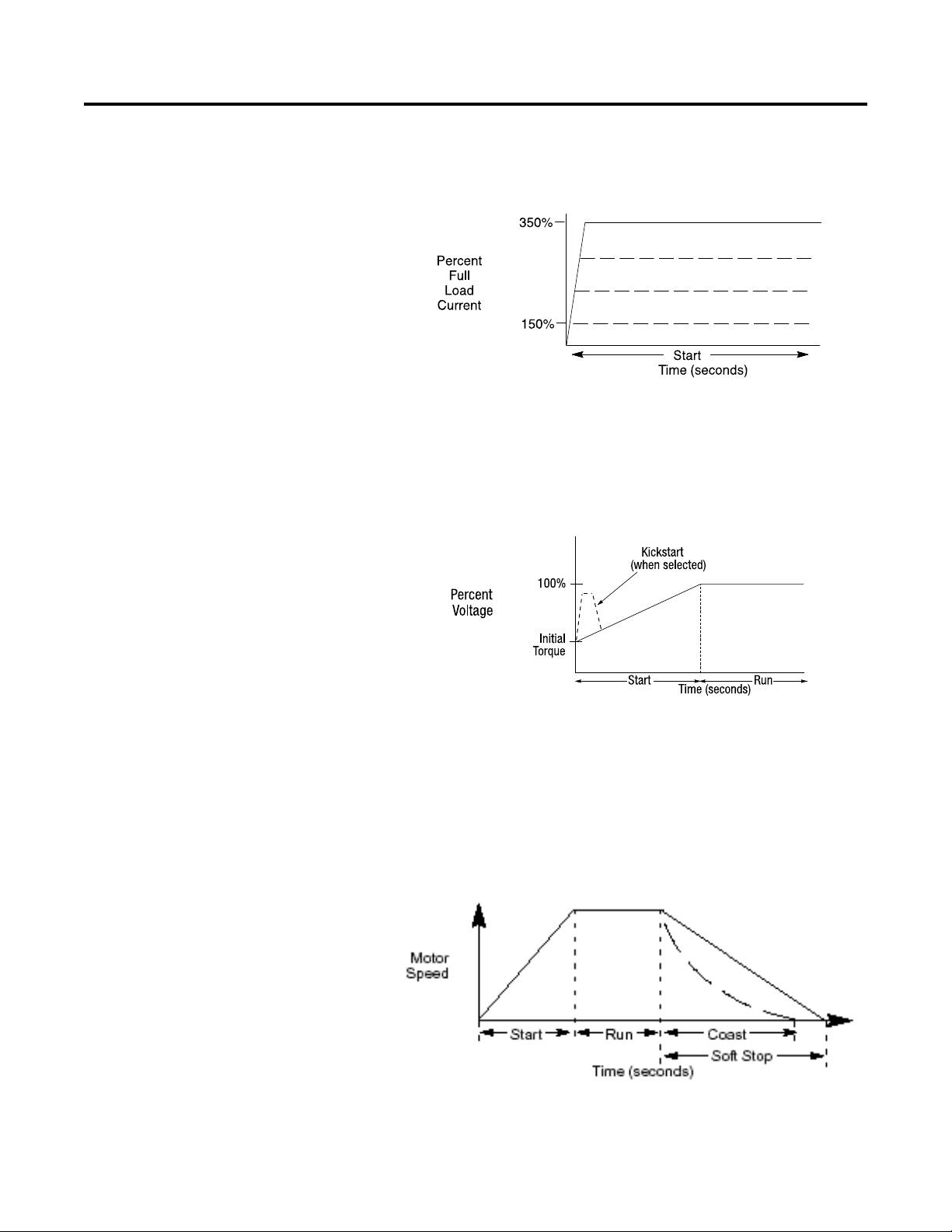
Current Limit Start
This starting mode is used when it is necessary to limit the maximum
starting current. It can be adjusted for 150...600% of full load amps.
Start times are selectable from 1...45 seconds.
Selectable Kick Start
A kickstart, or boost, at the beginning of the start mode is intended to
provide a current pulse of 450% of full load current. The kickstart
time is adjustable from 0.5...1.5 seconds. This allows the motor to
develop additional torque at start for loads which may need a boost to
get started.
Soft Stop
The Soft Stop function can be used with applications that require an
extended coast to rest. When enabled, the voltage ramp down time
can be selected from 1...90 seconds. The motor will stop when the
motor voltage drops to a point where the load torque is greater than
the motor torque.
Page 16
1-4 Product Overview
Bulletin 284
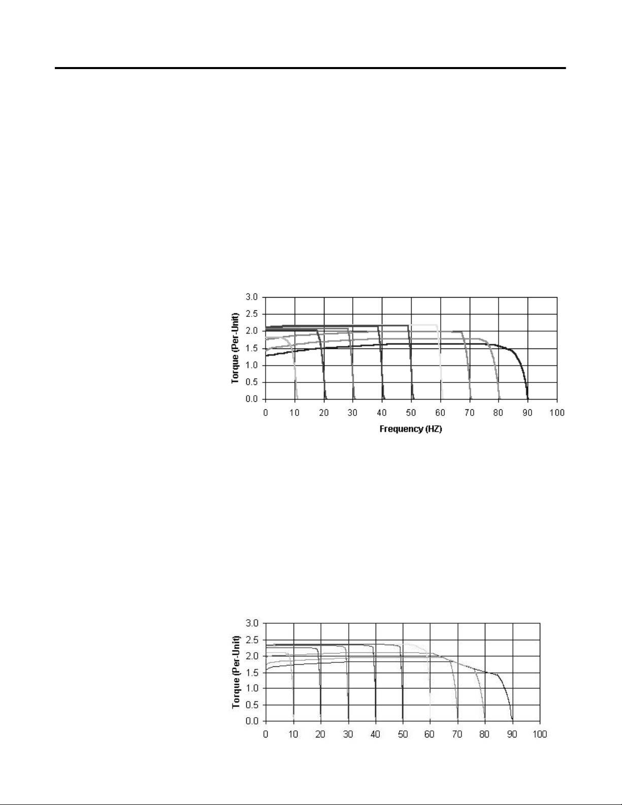
Sensorless Vector Performance (Volts per Hertz)
• Drive automatically provides auto boost (IR compensation) and
slip compensation
• Provides excellent speed regulation and high levels of torque
across the entire speed range of the drive and improved speed
regulation even as load increases.
• Most cost-effective performance when sensorless vector control
is not required.
• To select this method of operation, select H for the Mode of
Operation listed in the catalog structure. See
Publication 280-SG001_-EN-P.
Sensorless Vector Control
• Sensorless Vector Control provides exceptional speed regulation
and very high levels of torque across the entire speed range of the
drive
• The Autotune feature allows the Bulletin 284 ArmorStart
Distributed Motor Controller to adapt to individual motor
characteristics.
• To select this method of operation, select V for the Mode of
Operation listed in the catalog structure. See
Publication 280-SG001_-EN-P.
Page 17
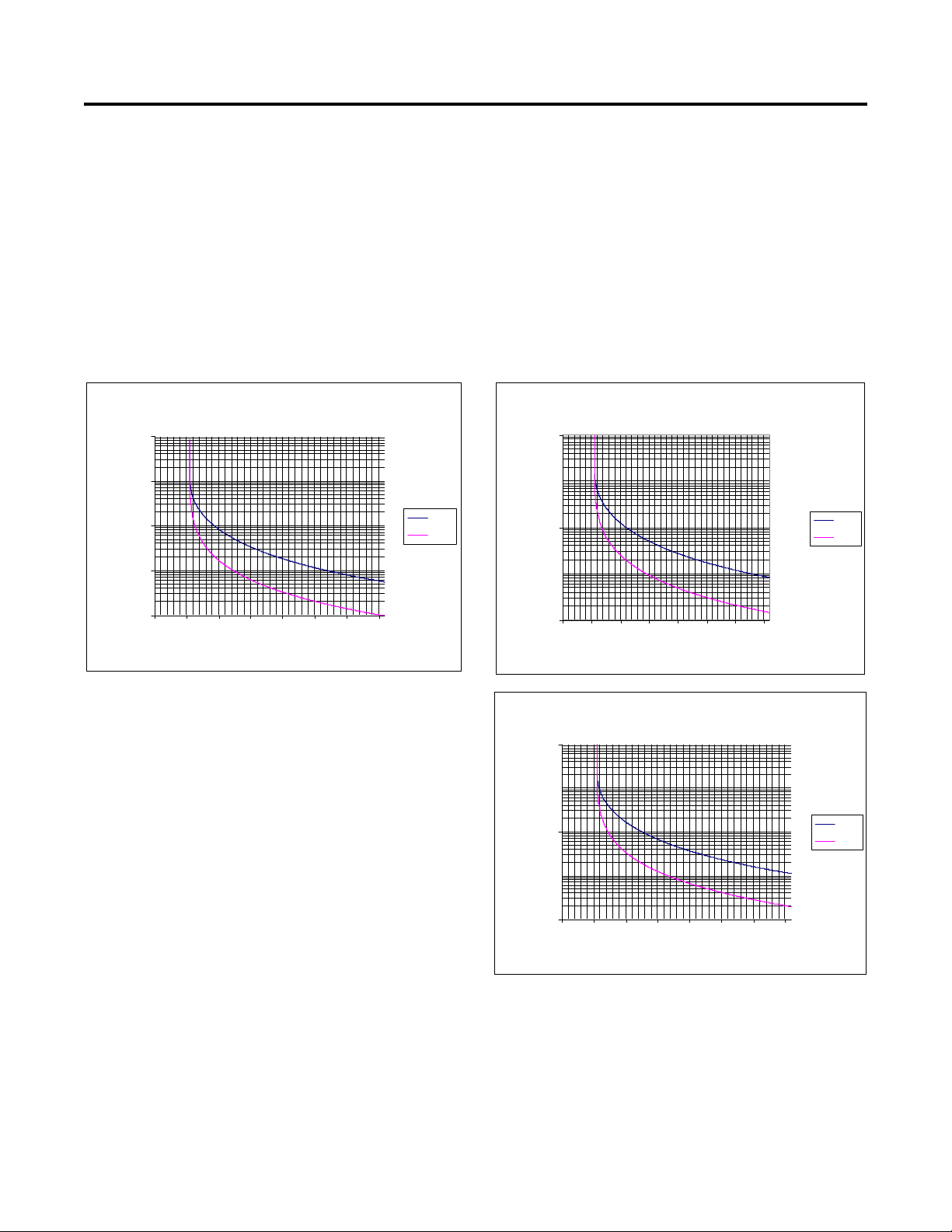
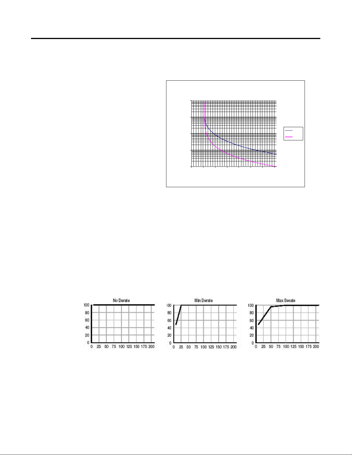
Description of Features Overload Protection
Class 15 Overload Curves
1
100
10000
0 100 200 300 400 500 600 700
Multiples for Full Load Current
Approximate Trip Time (sec)
Cold
Hot
Class 10 Ove rload Curv es
1
10
100
1000
10000
0 100 200 300 400 500 600 700
Multiples of Full Load Current
Approximate Trip Time (sec)
Cold
Hot
Class 20 Ove rload Curv es
1
100
10000
0 100 200 300 400 500 600 700
Multiples of Full Load Current
Approximate Trip Time (sec)
Cold
Hot
Class 10
Class 15
Class 20
%
%
of
%
The ArmorStart Distributed Motor Controller incorporates, as
standard, electronic motor overload protection. This overload
protection is accomplished electronically with an I
ArmorStart’s overload protection is programmable via the
communication network, providing the user with flexibility.
The Bulletin 280/281 overload trip class can be selected for class 10,
15, 20 protection. Ambient insensitivity is inherent in the electronic
design of the overload.
Figure 1.1 Overload Trip Curves
Product Overview 1-5
2
t algorithm. The
Page 18
1-6 Product Overview
Class 10 Overload Curv es
1
10
100
1000
10000
0 100 200 300 400 500 600 700
Multiples of Full Load Curre nt
Approximate Trip Time (sec)
Cold
Hot
Class 10
% of P132 (Motor NP Hertz) % of P132 (Motor NP Hertz)
% of P132 (Motor NP Hertz)
% of P133 (Motor OL Current)
% of P133 (Motor OL Current)
% of P133 (Motor OL Current)
The Bulletin 283 overload trip class allows for class 10 protection.
Ambient insensitivity is inherent in the electronic design of the
overload.
Figure 1.2 Overload Trip Curve
The Bulletin 284 ArmorStart Distributed Motor Controller
incorporates, as standard, electronic motor overload protection. This
2
overload protection is accomplished electronically with an I
t
algorithm. The ArmorStart’s overload protection is programmable via
the communication network providing the user with flexibility.
Programming the Motor OL Current parameter provides class 10
overload protection for the Bulletin 284 Distributed Motor Controller.
Ambient insensitivity is inherent in the electronic design of the
overload.
Figure 1.3 Overload Trip Curves
Page 19
Product Overview 1-7
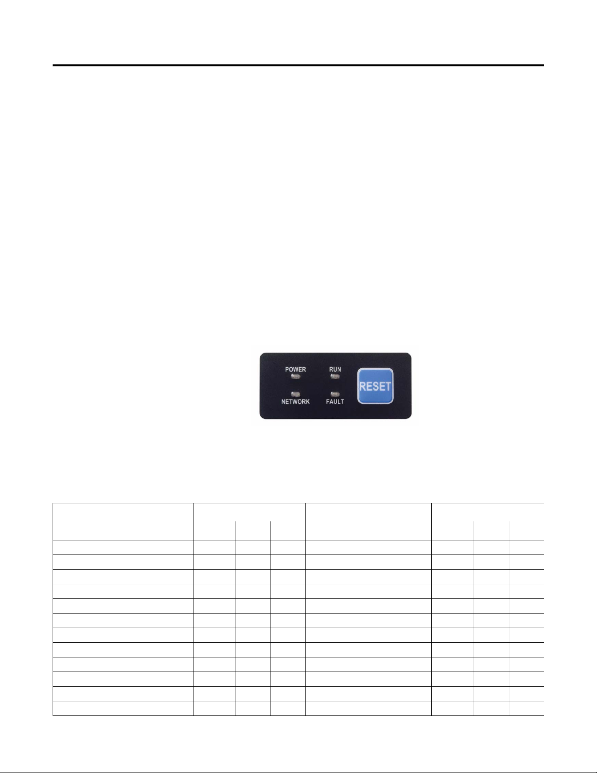
LED Status Indication
The LED Status Indication provides 4 status LEDs and a Reset
button. The LEDs provide status indication for the following:
•POWER LED
The LED is illuminated solid green when control power is present
and with the proper polarity
• RUN LED
This LED is illuminated solid green when a start command and
control power are present
•NETWORK LED
This bi-color (red/green) LED indicates the status of the
communication link
•FAULT LED
Indicates Controller Fault (Trip) condition
The “Reset Button” acts as a local trip reset.
Figure 1.4 Status Indication and Reset
Fault Diagnostics
Fault diagnostics capabilities built in the ArmorStart Distributed
Motor Controller help you pinpoint a problem for easy
troubleshooting and quick re-starting.
Fault Indication
• Short Circuit X X X • Miscellaneous Fault X X
• Overload X X X • Brake Fuse Detection X X
• Phase Loss X X X • Internal Comm. Fault X X
• Control Power Loss X X X • Shorted SCR X
• Control Power Fuse Detection X X X • Phase Rotation X
• Output Power Fuse Detection X X X • Heatsink Temperature Fault X
•I/O Fault X X X •DC Bus Fault X
• Over Temperature X X X • Ground Fault X
• DeviceNet™ Power Loss ➊ X X X • Overcurrent X
• EEprom Fault X X X • Restart Retries X
• Hardware Fault X X X • Stall X
• Phase Imbalance X X • Phase Short X
Available on Bulletin:
Fault Indication
280/281 283 284 280/281 283 284
➊ Not available on the Bulletin 280A/281A., 283A, or 284A.
Available on Bulletin:
Page 20

1-8 Product Overview
Inputs
The inputs are single-keyed (2 inputs per connector), which are
sourced from DeviceNet power (24V DC), with LED status indication
- Not available with on the Bulletin 280A/281A, 283A, or 284A.
Outputs
Two dual-key relay output connectors are supplied as standard. The
outputs are sourced from control power (A1 and A2). LED status
indication is also provided as standard for each output.
Gland Plate Entrance
The ArmorStart product offers two different methods of connecting
incoming three-phase and control power to the device. One method
offered is the traditional conduit entrance with a ¾ in. and 1 in.
conduit hole opening for wiring three-phase and control power. The
second method offers connectivity to the ArmorConnect™ power
media. Factory-installed receptacles are provided for connectivity to
both three-phase and control power media.
Motor Cable
With every ArmorStart Distributed Motor Controller, a 3-meter
unshielded 4-conductor cordset is provided with each unit as
standard. If the optional EMI filter is selected for Bulletin 284 units, a
shielded 4-conductor cordset is provided with each unit as standard.
ArmorStart with DeviceNet Network Capabilities
The ArmorStart Distributed Motor Controller delivers advanced
capabilities to access parameter settings and provides fault
diagnostics, and remote start-stop control. DeviceNet is the
communication protocol, provided with the ArmorStart Bulletin
280D/281D, 283D, or 284D Distributed Motor Controller.
ArmorStart with ArmorPoint® I/O
The Bulletin 280A/281A, 283A, and 284A ArmorStart Distributed
Motor Controller allows connectivity to the ArmorPoint backplane.
The ArmorPoint I/O system can communicate using DeviceNet,
ControlNet, or EtherNet communication protocols. In addition to the
different network protocols, the ArmorPoint Distributed I/O products
allow the I/O capability to be expanded beyond the standard two
outputs. Two dual-key relay output connectors are supplied as
standard. The outputs are sourced from control power (A1 and A2).
LED status indication is also provided as standard for each output.
When using the ArmorPoint backplane, a maximum of two
ArmorStart Distributed Motor Controllers can be connected to the
ArmorPoint Distributed I/O product.
Page 21

Product Overview 1-9
If the I/O capability of the Bulletin 280D/281D, 283D, or 284D
ArmorStart Distributed Motor Controller needs to be expanded
beyond the standard four inputs and two outputs, the ArmorStart
Distributed Motor Controller with the DeviceNet communication
protocol can be configured to the ADNX Architecture, in which the
ArmorStart is part of the DeviceNet subnet, using the Bulletin 1738ADNX ArmorPoint Distributed I/O product.
DeviceLogix™
DeviceLogix is a stand-alone Boolean program that resides within the
ArmorStart Distributed Motor Controller. DeviceLogix is
programmed using Boolean math operations, such as, AND, OR,
NOT, Timers, Counters, and Latches. DeviceLogix can run as a standalone application, independent of the network. However, 24V DC
must be supplied at the DeviceNet connector to power the inputs.
Peer to Peer Communications (ZIP)
The zone control capabilities of ArmorStart Distributed Motor
Controllers is ideal for large horsepower (0.5…10 Hp) motored
conveyors. The ArmorStart Distributed Motor Controllers have builtin DeviceNet communications, DeviceLogix technology, and the
added Zone Interlocking Parameters (ZIP) which allow one
ArmorStart to receive data directly, from up to four other DeviceNet
nodes, without going through a network scanner. These direct
communications between conveyor zones are beneficial in a merge,
diverter, or accumulation conveyor application.
Factory Installed Options Safety Monitor Option (Bulletins 280/281, 283, and 284)
The Safety Monitor Option allows for independent monitoring of the
output status of the device. The function is implemented using a
normally closed contact which complies with EN/IEC 60947-5-1 for
mechanically linked contacts. Two terminal blocks are provided as
the inputs which may be used with an external safety circuit. The
external safety circuit monitors the status of the contactor.
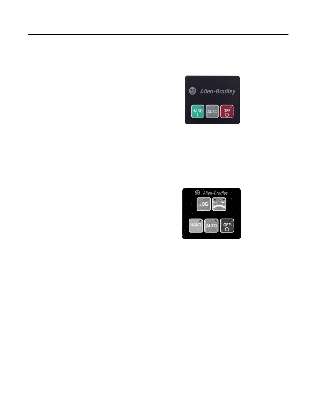
Optional HOA Keypad Configuration (Bulletin 280/281 only)
The ArmorStart offers two optional factory-installed Hand/Off/Auto
(HOA) configurations: Standard and Forward/Reverse HOA.
Figure 1.5 Optional HOA Configuration
Page 22
1-10 Product Overview
Optional HOA Keypad Configuration (Bulletin 283 only)
The ArmorStart offers an optional factory-installed Hand/Off/Auto
(HOA) configuration:
Figure 1.6 Optional HOA Configuration
Optional HOA Selector Keypad with Jog Function (Bulletin 284
only)
The HOA Selector Keypad with Jog Function allows for local start/
stop control with capabilities to jog in forward/reverse motor
directions.
Figure 1.7 Optional HOA with Jog Function Configuration
Source Brake Contactor (Bulletins 283 and 284 only)
An internal contactor is used to switch the electromechanical motor
brake on/off. The motor brake is powered from the main power
circuit. A customer-accessible 3.0 A fuse is provided to protect the
brake cable. A 3 meter, 3-pin cable for connection to the motor brake
is provided as standard when the option is selected.
EMI Filter (Bulletin 284 only)
The EMI Filter option is required if the Bulletin 284 ArmorStart
Distributed Motor Controller must be CE-compliant. If the EMI Filter
is selected, a 3 meter shielded 4-conductor cordset is provided as
standard. This option is only available with sensorless vector control.
Dynamic Brake (Bulletin 284 only)
A 3 meter 3-pin cable for connection to a dynamic brake module is
provided as standard when this option is selected.
Accessories for available dynamic brake modules.
See Appendix G,
Page 23

Product Overview 1-11
Dynamic Brake Resistor (Bulletin 284 only)
The IP67 Dynamic Brake Resistor plug and play design offers
simplicity in writing and installation. The factory installed option of
DB1 must be selected in order to have the quick disconnect
connectivity. The cable length of the IP67 Dynamic Brake Resistor is
available in two lengths, 0.5 meter and 1 meter. See Appendix G,
Accessories, for available IP67 Dynamic Brake Resistors.
Control Brake Contactor (Bulletin 284 only)
An internal contactor is used to switch the electromechanical motor
brake On/Off. The motor brake is powered from the control voltage
circuit. A customer accessible 3.0 A fuse is provided to protect the
brake cable. One 3-meter 3-pin cable for connection to the motor
brake is provided as standard when this option is selected.
Output Contactor (Bulletin 284 only)
An internal contactor will be sourced from control voltage to isolate
the load side of the Bulletin 284 ArmorStart Distributed Motor
Controller. When control power is applied, the output contactor is
closed, and when control power is removed, the output contact opens.
There is no switching element, such as a relay, in the system. If
control power is lost then the output contactor will open, since its coil
power is lost. A sequenced stop involving the output contactor cannot
be performed.
Shielded Motor Cable (Bulletin 284 only)
A 3 meter shielded 4-conductor cordset is provided instead of the 3
meter unshielded 4-conductor cordset. If the EMI Filter is selected, a
3 meter shielded 4-conductor cordset is provided as standard.
0…10V Analog Input (Bulletin 284 only)
The Bulletin 284 Distributed Motor Controller with Sensorless Vector
Control provides a 0…10V analog input. The 0…10V Analog Input
is a factory installed option that provides a 0…10V external
frequency command from the 0…10V or +/-10V analog input or
remote potentiometer. A 5-pin micro receptacle is provided for
connectivity for customer connection. A shielded 5-conductor cordset
or patch cord is recommended.
Page 24

1-12 Product Overview
Notes:
Page 25

Chapter 2
Installation and Wiring
Receiving It is the responsibility of the user to thoroughly inspect the equipment
before accepting the shipment from the freight company. Check the
item(s) received against the purchase order. If any items are damaged,
it is the responsibility of the user not to accept delivery until the
freight agent has noted the damage on the freight bill. Should any
concealed damage be found during unpacking, it is again the
responsibility of the user to notify the freight agent. The shipping
container must be left intact and the freight agent should be requested
to make a visual inspection of the equipment.
Unpacking Remove all packing material, wedges, or braces from within and
around the starter. Remove all packing material from device(s).
Inspecting After unpacking, check the nameplate catalog number(s) against the
purchase order.
Storing The controller should remain in its shipping container prior to
installation. If the equipment is not to be used for a period of time, it
must be stored according to the following instructions in order to
maintain warranty coverage.
• Store in a clean, dry location.
• Store within an ambient temperature range of –25°C…+85°C
(–13°F…+185°F).
• Store within a relative humidity range of 0…95%,
noncondensing.
• Do not store equipment where it could be exposed to a corrosive
atmosphere.
• Do not store equipment in a construction area.
Page 26
2-2 Installation and Wiring
ATTENTION
!
ATTENTION
!
ATTENTION
!
ATTENTION
!
ATTENTION
!
General Precautions In addition to the precautions listed throughout this manual, the
following statements, which are general to the system, must be read
and understood.
The controller contains ESD (electrostatic
discharge)-sensitive parts and assemblies. Static
control precautions are required when installing,
testing, servicing, or repairing the assembly.
Component damage may result if ESD control
procedures are not followed. If you are not familiar
with static control procedures, refer to Publication
8000-4.5.2, Guarding against Electrostatic
Discharge, or any other applicable ESD protection
handbooks.
An incorrectly applied or installed controller can
damage components or reduce product life. Wiring
or application errors, such as undersizing the motor,
incorrect or inadequate AC supply, or excessive
ambient temperatures, may result in malfunction of
the system.
Precautions for Bulletin 284
Applications
Only personnel familiar with the controller and
associated machinery should plan or implement the
installation, startup, and subsequent maintenance of
the system. Failure to do this may result in personal
injury and/or equipment damage.
The drive contains high voltage capacitors which
take time to discharge after removal of mains
supply. Before working on drive, ensure isolation of
mains supply from line inputs (R, S, T [L1, L2, L3]).
Wait three minutes for capacitors to discharge to
safe voltage levels. Failure to do so may result in
personal injury or death.
Darkened display LEDs are not an indication that
capacitors have discharged to safe voltage levels.
Only qualified personnel familiar with adjustable
frequency AC drives and associated machinery
should plan or implement the installation, startup,
and subsequent maintenance of the system. Failure
to do this may result in personal injury and/or
equipment damage.
Page 27
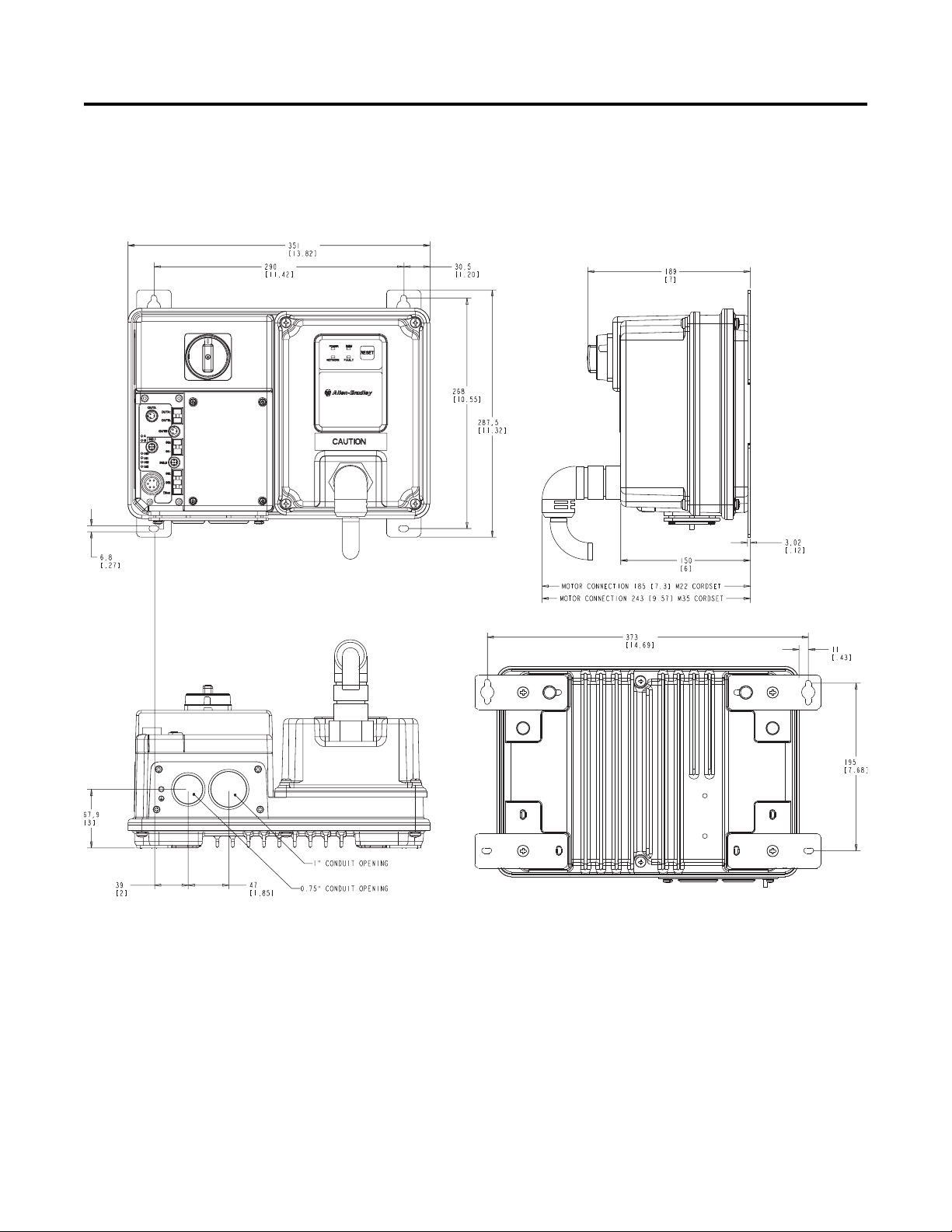
Installation and Wiring 2-3
Dimensions for Bulletin 280/281 Dimensions are shown in millimeters (inches). Dimensions are not
intended to be used for manufacturing purposes. All dimensions are
subject to change.
Figure 2.1 Dimensions for IP67/NEMA Type 4 with Conduit Entrance
Page 28
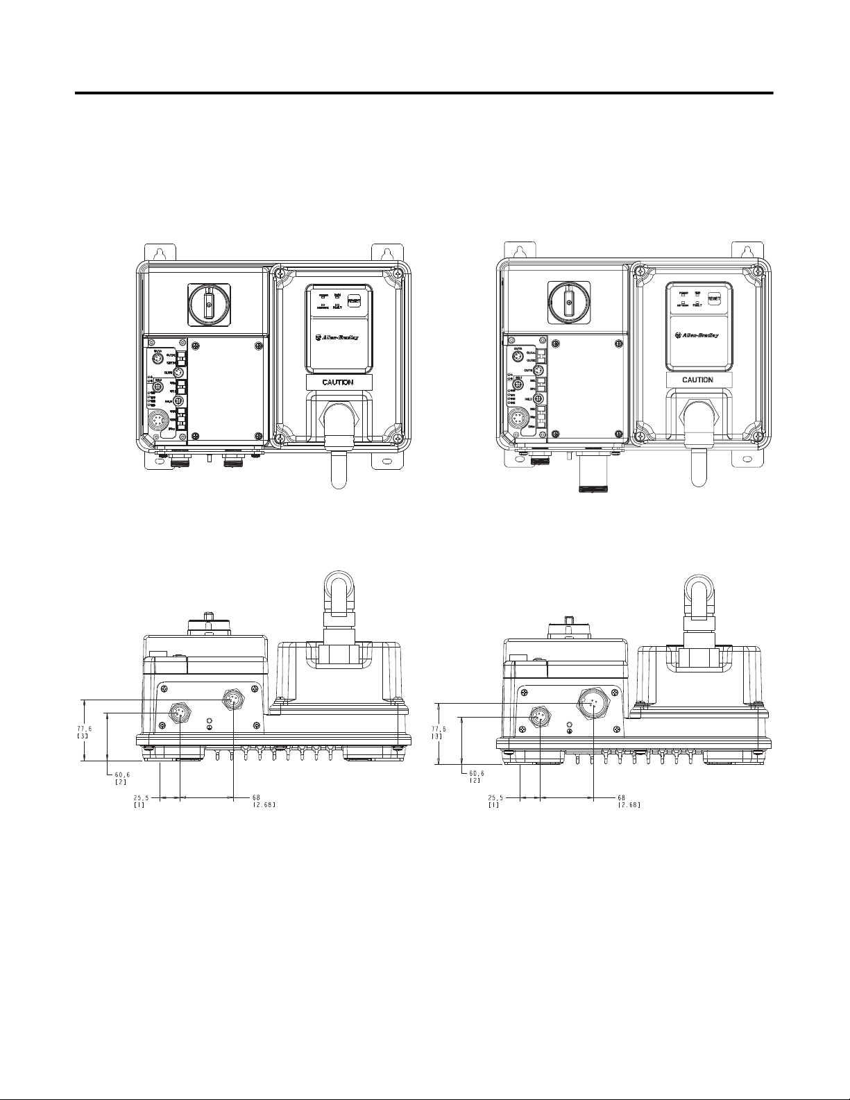
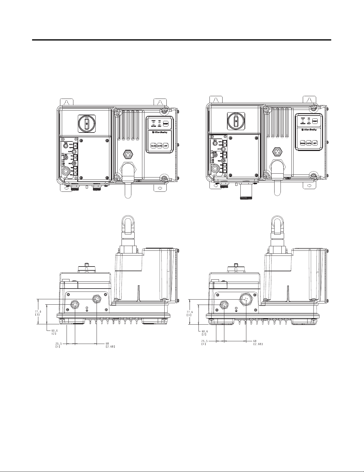
2-4 Installation and Wiring
ArmorStart® with a 10 A
Short-Circuit Protection Rating
ArmorStart® with a 25 A
Short-Circuit Protection Rating
Dimensions for Bulletin 280/281,
Continued
Dimensions are shown in millimeters (inches). Dimensions are not
intended to be used for manufacturing purposes. All dimensions are
subject to change.
Figure 2.2 Dimensions for IP67/NEMA Type 4 with ArmorConnect™
Connectivity
Page 29
Installation and Wiring 2-5
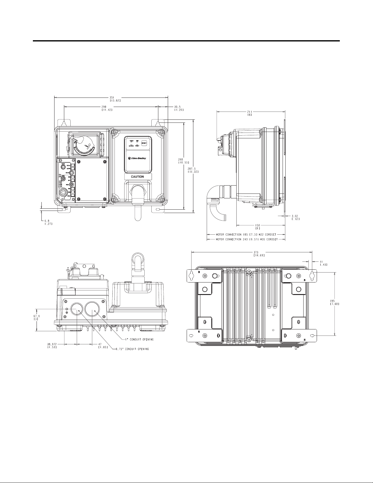
Dimensions for Bulletin 280/281,
Continued
Dimensions are shown in millimeters (inches). Dimensions are not
intended to be used for manufacturing purposes. All dimensions are
subject to change.
Figure 2.3 Dimensions for NEMA Type 4X with Conduit Entrance
Page 30
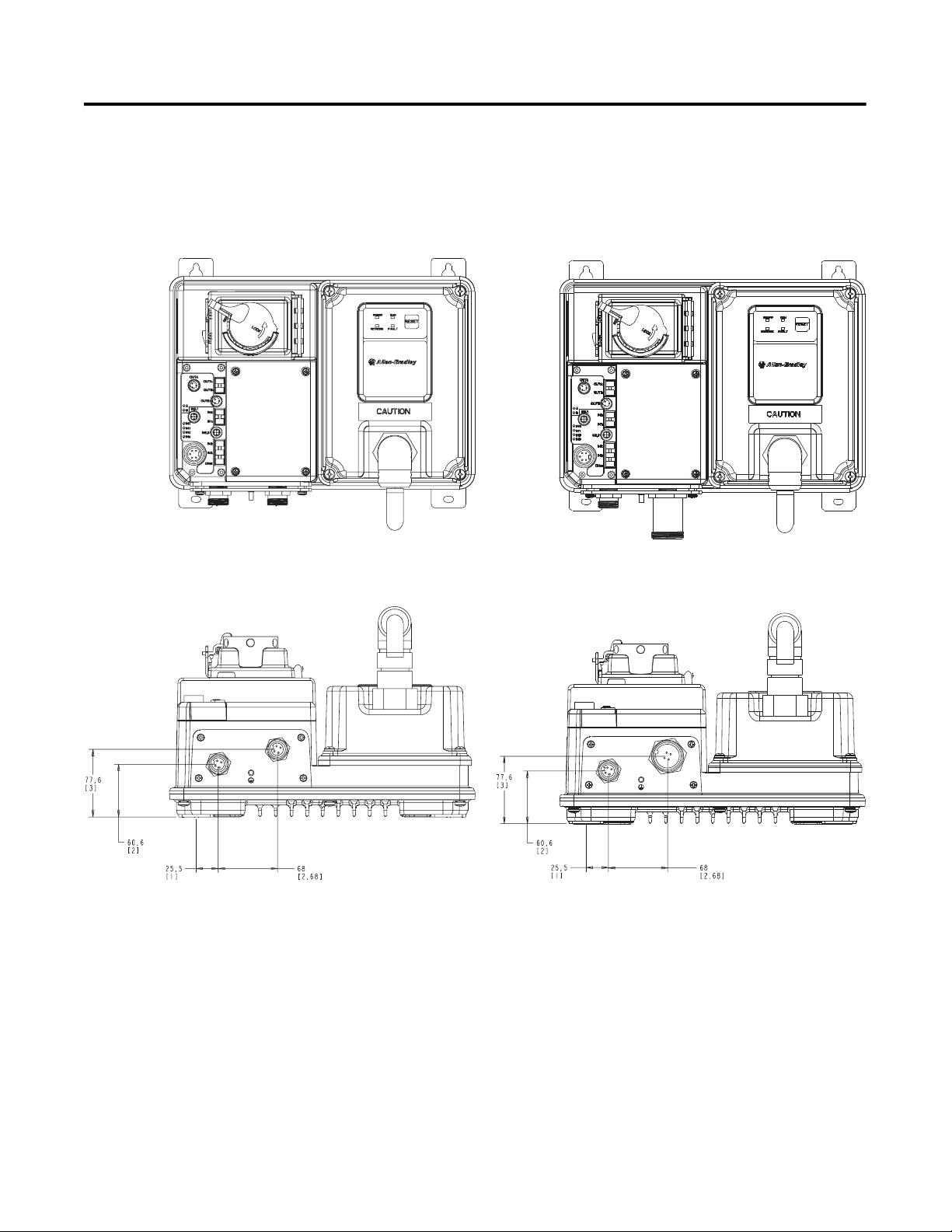
2-6 Installation and Wiring
Dimensions for Bulletin 280/281,
Continued
Dimensions are shown in millimeters (inches). Dimensions are not
intended to be used for manufacturing purposes. All dimensions are
subject to change.
Figure 2.4 Dimensions for Type 4X with ArmorConnect Connectivity
Page 31
Installation and Wiring 2-7
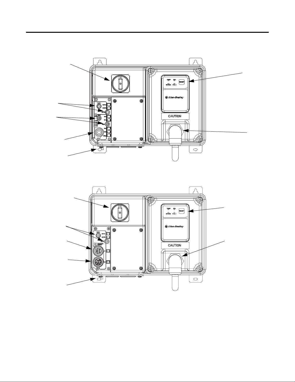
LED Status
Indication
Motor
Connection
DeviceNet
Connection
(Mini/M18)
Local Disconnect
2 Outputs
(Micro/M12)
4 Inputs
(Micro/M12)
Ground
Terminal
LED Status
Indication
Motor
Connection
Local Disconnect
2 Outputs
(Micro/M12)
ArmorPoint
ArmorPoint
Interface (IN)
Interface (OUT)
Ground
Te r mi n al
Figure 2.5 Bulletin 280D/281D ArmorStart® with DeviceNet™
Communication Protocol
Figure 2.6 Bulletin 280A/281A ArmorStart for the ArmorPoint® Backplane
Page 32

2-8 Installation and Wiring
Control Power
Control Power
Three-Phase Power
Three-Phase Power
Ground Terminal
Ground Terminal
Figure 2.7 Bulletin 280D/281D ArmorStart with ArmorConnect Connectivity
Page 33

Installation and Wiring 2-9
Dimensions for Bulletin 283 Dimensions are shown in millimeters (inches). Dimensions are not
intended to be used for manufacturing purposes. All dimensions are
subject to change.
Figure 2.8 Dimensions for IP67/NEMA Type 4 with Conduit Entrance
Page 34
2-10 Installation and Wiring
ArmorStart device with a 10 A short circuit protection rating ArmorStart device with a 25 A short circuit protection rating
Dimensions for Bulletin 283,
Continued
Dimensions are shown in millimeters (inches). Dimensions are not
intended to be used for manufacturing purposes. All dimensions are
subject to change.
Figure 2.9 Dimensions for IP67/NEMA Type 4 with ArmorConnect™
Connectivity
Page 35

Installation and Wiring 2-11
Dimensions for Bulletin 283,
Continued
Dimensions are shown in millimeters (inches). Dimensions are not
intended to be used for manufacturing purposes. All dimensions are
subject to change.
Figure 2.10 Dimensions for NEMA Type 4X with Conduit Entrance
Page 36

2-12 Installation and Wiring
ArmorStart device with a 10 A short circuit protection rating ArmorStart device with a 25 A short circuit protection rating
Dimensions for Bulletin 283,
Continued
Dimensions are shown in millimeters (inches). Dimensions are not
intended to be used for manufacturing purposes. All dimensions are
subject to change.
Figure 2.11 Dimensions for NEMA Type 4X with ArmorConnect Connectivity
Page 37

Installation and Wiring 2-13
LED Status
Indication
Motor
Connection
DeviceNet
Connection
(Mini/M18)
Local Disconnect
2 Outputs
(Micro/M12)
4 Inputs
(Micro/M12)
Source Brake
Connector
Ground
Te r mi n a l
LED Status
Indication
Motor
Connection
ArmorPoint
Local Disconnect
2 Outputs
(Micro/M12)
ArmorPoint
Source Brake
Connector
Interface
(IN)
Interface
(OUT)
Ground Terminal
Figure 2.12 Bulletin 283D ArmorStart® with DeviceNet™ Communication
Protocol
Figure 2.13 Bulletin 283A ArmorStart for the ArmorPoint® Backplane
Page 38

2-14 Installation and Wiring
Dimensions for Bulletin 284 Dimensions are shown in millimeters (inches). Dimensions are not
intended to be used for manufacturing purposes. All dimensions are
subject to change.
Figure 2.14 Dimensions for 1 Hp and below @ 230V AC, 2 Hp and below @
460V AC, and 2 Hp and below @ 575V AC, IP67/NEMA Type 4 with
Conduit Entrance
Page 39

Installation and Wiring 2-15
ArmorStart device with a 10 A short circuit protection rating
Dimensions for Bulletin 284,
Continued
Dimensions are shown in millimeters (inches). Dimensions are not
intended to be used for manufacturing purposes. All dimensions are
subject to change.
Figure 2.15 Dimensions for 1 Hp and below @ 230V AC, 2 Hp and below @
460V AC, and 2 Hp and below @ 575V AC, IP67/NEMA Type 4 with
ArmorConnect™ Connectivity
Page 40

2-16 Installation and Wiring
Dimensions for Bulletin 284,
Continued
Dimensions are shown in millimeters (inches). Dimensions are not
intended to be used for manufacturing purposes. All dimensions are
subject to change.
Figure 2.16 Dimensions for 2 Hp @ 230V AC, 3 Hp and above @ 460V AC, and
3 Hp and above @ 575V AC, IP67/NEMA Type 4 with Conduit
Entrance
Page 41

Installation and Wiring 2-17
ArmorStart device with a 25 A short circuit protection rating
Dimensions for Bulletin 284,
Continued
Dimensions are shown in millimeters (inches). Dimensions are not
intended to be used for manufacturing purposes. All dimensions are
subject to change.
Figure 2.17 Dimensions for 2 Hp @ 230V AC, 3 Hp and above @ 460V AC, and
3 Hp and above @ 575V AC, IP67/NEMA Type 4 with
ArmorConnect Connectivity
Page 42

2-18 Installation and Wiring
Dimensions for Bulletin 284,
Continued
Dimensions are shown in millimeters (inches). Dimensions are not
intended to be used for manufacturing purposes. All dimensions are
subject to change.
Figure 2.18 Dimensions for 1 Hp and below @ 230V AC, 2 Hp and below @
460V AC, and 2 Hp and below @ 575V AC, NEMA Type 4X with
Conduit Entrance
Page 43

Installation and Wiring 2-19
ArmorStart device with a 10 A short circuit protection rating
Dimensions for Bulletin 284,
Continued
Dimensions are shown in millimeters (inches). Dimensions are not
intended to be used for manufacturing purposes. All dimensions are
subject to change.
Figure 2.19 Dimensions for 1 Hp and below @ 230V AC, 2 Hp and below @
460V AC, and 2 Hp and below @ 575V AC, NEMA Type 4X with
ArmorConnect Connectivity
Page 44

2-20 Installation and Wiring
Dimensions for Bulletin 284,
Continued
Dimensions are shown in millimeters (inches). Dimensions are not
intended to be used for manufacturing purposes. All dimensions are
subject to change.
Figure 2.20 Dimensions for 2 Hp @ 230V AC, 3 Hp and above @ 460V AC, and
3 Hp and above @ 575V AC, NEMA Type 4X with Conduit Entrance
Page 45

Installation and Wiring 2-21
ArmorStart device with a 25 A short circuit protection rating
Dimensions for Bulletin 284,
Continued
Dimensions are shown in millimeters (inches). Dimensions are not
intended to be used for manufacturing purposes. All dimensions are
subject to change.
Figure 2.21 Dimensions for 2 Hp @ 230V AC, 3 Hp and above @ 460V AC, and
3 Hp and above @ 575V AC, NEMA Type 4X with ArmorConnect
Connectivity
Page 46

2-22 Installation and Wiring
LED Status
Indication
Motor
Connector
DeviceNet
Connection
(Mini/M18)
Local Disconnect
2 Outputs
(Micro/M12)
4 Inputs
(Micro/M12)
Dynamic
Brake Connector
Source Brake
Connector
0…10V
➋
Analog Input
Ground
Te r mi n a l
Figure 2.22 Bulletin 284 ArmorStart
➋ Available only with the Bulletin 284 with sensorless vector control.
Page 47
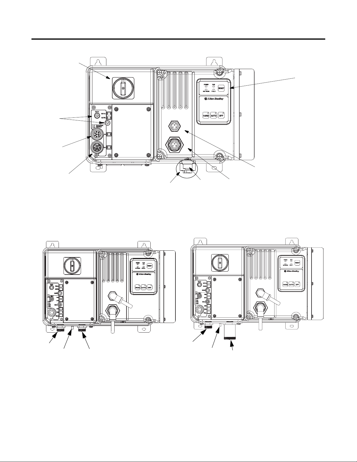
Figure 2.23 Bulletin 284 ArmorStart
LED Status
Indication
Motor
Connector
ArmorPoint
Interface
(Out)
Local Disconnect
2 Outputs
(Micro/M12)
Dynamic
Brake Connector
Source/Control Brake
Connector
0…10V Analog①
Input Connector
ArmorPoint
Interface
(In)
Control
Control Power
Three-Phase Power
Three-Phase Power
Ground
Te r mi n al
Ground
Powe r
Te r mi n al
①
Available only with the Bulletin 284 with sensorless vector control.
Installation and Wiring 2-23
Figure 2.24 Bulletin 284 ArmorStart with ArmorConnect
Page 48

2-24 Installation and Wiring
Wiring Power, Control, Safety Monitor Inputs, and Ground Wiring
Table 2.1 provides the power, control, and ground wire capacity and
the tightening torque requirements. The power, control, ground, and
safety monitor terminals will accept a maximum of two wires per
terminal.
Table 2.1 Power, Control, Safety Monitor Inputs, Ground Wire Size, and
Torque Specifications
Terminals Wire Size Torque Wire Strip Length
Power
and
Ground
Control and Safety
Monitor Inputs
Primary/Secondary
Terminal:
1.5…4.0 mm
(#16 …#10 AWG)
1.0 mm
(#18…#10 AWG)
2
…4.0 mm2
2
Primary Terminal:
Secondary Terminal:
10.8 lb.-in.
(1.2 N•m)
4.5 lb.-in
(0.5 N•m)
6.2 lb.-in
(0.7 N•m)
0.35 in. (9 mm)
0.35 in. (9 mm)
Page 49

Installation and Wiring 2-25
Primaries
Secondaries
Terminal Designations As shown in the next figures, the ArmorStart Distributed Motor Controller
contains terminals for power, control, safety monitor inputs, and ground
wiring. Access can be gained by removing the terminal access cover plate.
Figure 2.25 Bulletin 280/281 ArmorStart Power, Control and Terminals
Figure 2.26 Bulletin 283 ArmorStart Power and Control Terminals
Page 50

2-26 Installation and Wiring
Figure 2.27 Bulletin 284 ArmorStart Power and Control Terminals
Table 2.2 Power, Control, Safety Monitor, and Ground Terminal Designations
Terminal Designations No. of Poles Description
SM1 ➊ 2 Safety Monitor Input
SM2 ➊ 2 Safety Monitor Input
A1 (+) 2 Control Power Input
A2 (-) 2 Control Power Common
PE 2 Ground
1/L1 2 Line Power Phase A
3/L3 2 Line Power Phase B
5/L5 2 Line Power Phase C
➊ Only available with the Safety Monitor option.
Page 51

Installation and Wiring 2-27
Optional Locking Clip The clam shell design clips over the ArmorStart motor connector and
motor cable to limit customer access from disconnecting the motor
cable on the ArmorStart Distributed Motor Controller. The locking
clip is an optional device that can be used, if desired.
Figure 2.28 Bulletin 280/281Installation of Locking Clip
Figure 2.29 Bulletin 283/284 Installation of Locking Clip
Page 52

2-28 Installation and Wiring
Operation of NEMA Type 4X
Disconnect Handle
To Open Disconnect Handle
1. Rotate locking ring 45° until it stops.
2. To open, push the tab on the left-hand side and lift the access
cover.
Note: The access door can not be closed when 140 (black handle) is
in the OFF position.
To Close Disconnect Handle for Lockout/Tag out
With disconnect handle in the ON position, rotate lockout/tag out ring
counterclockwise until the disconnect handle is in the OFF position.
Note: The disconnect handle is designed to be used with a 1/4 in.
lockout/tag out padlock.
Page 53

ArmorConnect Power Media Description
RESET
OFF
Bulletin 280/281
ArmorStart
Bulletin 283
ArmorStart
Bulletin 284
ArmorStart
PLC
Bulletin 1492FB
Branch Circuit
Protective Device
Enclosure
Bulletin 1606
Power Supply
Bulletin 800F
Emergency Stop
Pushbutton
1606-XLSDNET4
DeviceNet
Power Supply
The ArmorConnect power media offers both three-phase and control
power cable system of cord sets, patch cords, receptacles, tees,
reducers and accessories to be utilized with the ArmorStart
Distributed Motor Controller. These cable system components allow
quick connection of ArmorStart Distributed Motor Controllers, there
by reducing installation time. They provide for repeatable, reliable
connection of the three-phase and control power to the ArmorStart
Distributed Motor Controller and motor by providing a plug-and-play
environment that also avoids system mis-wiring. When specifying
power media for use with the ArmorStart Distributed Motor
Controllers (Bulletin 280/281, 283 and 284) use only the Bulletin 280
ArmorConnect power media.
Figure 2.30 Three-Phase Power System Overview
Installation and Wiring 2-29
➊ Three-Phase Power Trunk- PatchCord cable with integral female or male connector on each end
Example Part Number: 280-PWR35A-M*
➋ Three-Phase Drop Cable- PatchCord cable with integral female or male connector on each end
Example Part Number: 280-PWR22A-M*
➌ Three-Phase Power Tees and Reducer -
Tee connects to a single drop line to trunk with quick change connectors – Part Number: 280-T35
Reducing Tee connects to a single drop line (Mini) to trunk (Quick change) connector – Part Number: 280-RT35
Reducer connects from quick change male connector to mini female connector– Part Number: 280-RA35
➍ Three-Phase Power Receptacles -
Female receptacles are a panel mount connector with flying leads – Part Number: 280-M35F-M1
Page 54

2-30 Installation and Wiring
RESET
OFF
Bulletin 280/281
ArmorStart
Bulletin 283
ArmorStart
Bulletin 284
ArmorStart
PLC
Bulletin 1492FB
Branch Circuit
Protective Device
Enclosure
Bulletin 1606
Power Supply
Bulletin 800F
Emergency Stop
Pushbutton
1606-XLSDNET4
DeviceNet
Power Supply
Figure 2.31 Control Power Media System Overview
➏ Control Power Media Patchcords - PatchCord cable with integral female or male connector on each end
Example Part Number: 889N-F65GFNM-*
➐ Control Power Tees - The E-stop In Tee (Part Number: 898N-653ST-NKF) is used to connect to the Bulletin 800F On-Machine E-Stop station using a
control power media patchcord. The E-stop Out tee (Part Number: 898N-653ES-NKF) is used with cordset or patchcord to connect to the ArmorStart
Distributed Motor Controller.
➑ Control Power Receptacles - Female receptacles are a panel mount connector with flying leads –
Part Number: 888N-D65AF1-*
Page 55

Installation and Wiring 2-31
Control Power Receptacle
Three-Phase Power Receptacle
Control Power Receptacle
Three-Phase Power Receptacle
ArmorStart devices with 10 A short
circuit protection rating
ArmorStart devices with 25 A short
circuit protection rating
3/4 in. Lock Nut 1 in. Lock Nut
Thomas & Betts Cord Grip
Part Number: 2931NM
3/4 in. Stain Relief Cord Connector
Cable Range: 0.31…0.56 in.
Used with Control Power Media
Cordset - Example Part Number:
889N-M65GF-M2
Thomas & Betts Cord Grip
Part Number: 2940NM
1 in. Stain Relief Cord Connector
Cable Range: 0.31…0.56 in.
Used with Three-Phase Power
Media Cordset - Example Part
Number: 280-PWR22G-M1
Cord Grips for ArmorStart Devices with 10 A short circuit protection rating
3/4 in. Lock Nut 1 in. Lock Nut
Thomas & Betts Cord Grip
Part Number: 2931NM
3/4 in. Stain Relief Cord Connector
Cable Range: 0.31…0.56 in.
Used with Control Power Media
Cordset - Example Part Number:
889N-M65GF-M2
Thomas & Betts Cord Grip
Part Number: 2942NM
1 in. Stain Relief Cord Connector
Cable Range: 0.70…0.95 in.
Used with Three-Phase Power
Media Cordset - Example Part
Number: 280-PWR35G-M1
Cord Grips for ArmorStart Devices with 25 A short circuit protection rating
ArmorStart with ArmorConnect Connectivity
Installing ArmorConnect Power Media using CordSets
Page 56

2-32 Installation and Wiring
Terminal Designations Description Color Code
A1 (+) Control Power Input Blue
A2 (-) Control Power Common Black
PE Ground Green/Yellow
1/L1 Line Power - Phase A Black
2/L2 Line Power - Phase B White
3/L3 Line Power - Phase C Red
ArmorConnect Cable Ratings
The ArmorConnect power media cables are rated per UL Type TC
600V 90 °C Dry 75 °C Wet, Exposed Run (ER) or MTW 600V 90 °C
or STOOW 105 °C 600V - CSA STOOW 600V FT2.
Branch Circuit Protection Requirements for ArmorConnect
Three-Phase Power Media
When using ArmorConnect three-phase power media, only fuses can
be used for the motor branch circuit protective device, for the group
motor installations. The following fuse types are recommended: Class
CC, T, or J type fuses.
Maximum Ratings
Voltage (V) 480Y/277 480/480 600Y/347 600/600
Sym. Amps RMS 65 kA 65 kA 65 kA 65 kA
Time Delay Fuse 50 A 30 A 30 A 30 A
Non-Delay Fuse 100 A 60 A 60 A 60 A
Page 57

Installation and Wiring 2-33
ATTENTION
!
AC Supply Considerations for
Bulletin 284 units
Ungrounded and High Resistive Distribution Systems
The Bulletin 284 contains protective MOVs that are
referenced to ground. These devices should be disconnected
if the Bulletin 284 is installed on an ungrounded and high
resistive distribution system.
Disconnecting MOVs
To prevent drive damage, the MOVs connected to ground must be
disconnected if the drive is installed on an ungrounded and high
resistive distribution system where the line-to-ground voltages on any
phase could exceed 125% of the nominal line-to-line voltage. To
disconnect the MOVs, remove the jumper shown in Figure 2.33,
Jumper Removal.
1. Before installing the Bulletin 284, loosen four mounting screws.
2. Unplug starter module from the base unit by pulling forward.
Page 58

2-34 Installation and Wiring
Remove Jumper
ATTENTION
!
Figure 2.32 Removal of Control Module
Figure 2.33 Jumper Removal
Do not remove this jumper if the unit is equipped with an
EMI filter installed.
Page 59

Installation and Wiring 2-35
Group Motor Installations for USA
and Canada Markets
Wiring and Workmanship
Guidelines
The ArmorStart Distributed Motor Controllers are listed for use with
each other in group installations per NFPA 79, Electrical Standard for
Industrial Machinery. When applied according to the group motor
installation requirements, two or more motors, of any rating or
controller type, are permitted on a single branch circuit. Group Motor
Installation has been successfully used for many years in the USA and
Canada.
Note: For additional information regarding group motor
installations with the ArmorStart Distributed Motor
Controller, see Appendix C.
In addition to conduit and seal-tite raceway, it is acceptable to utilize
cable that is dual rated Tray Cable, Type TC-ER and Cord, STOOW,
for power and control wiring on ArmorStart installations. In the USA
and Canada installations, the following guidance is outlined by the
NEC and NFPA 79.
In industrial establishments where the conditions of maintenance and
supervision ensure that only qualified persons service the installation,
and where the exposed cable is continuously supported and protected
against physical damage using mechanical protection, such as struts,
angles, or channels, Type TC tray cable that complies with the crush
and impact requirements of Type MC (Metal Clad) cable and is
identified for such use with the marking Type TC-ER (Exposed
Run)* shall be permitted between a cable tray and the utilization
equipment or device as open wiring. The cable shall be secured at
intervals not exceeding 1.8 m (6 ft) and installed in a “good workmanlike” manner. Equipment grounding for the utilization equipment
shall be provided by an equipment grounding conductor within the
cable.
*Historically cable meeting these crush and impact requirements
were designated and marked “Open Wiring”. Cable so marked is
equivalent to the present Type TC-ER and can be used.
While the ArmorStart is intended for installation in factory floor
environments of industrial establishments, the following must be
taken into consideration when locating the ArmorStart in the
application: Cables, including those for control voltage including
24V DC and communications, are not to be exposed to an operator or
building traffic on a continuous basis. Location of the ArmorStart to
minimize exposure to continual traffic is recommended. If location to
minimize traffic flow is unavoidable, other barriers to minimize
inadvertent exposure to the cabling should be considered. Routing
cables should be done in such a manner to minimize inadvertent
exposure and/or damage.
Page 60

2-36 Installation and Wiring
Additionally, if conduit or other raceways are not used, it is
recommended that strain relief fittings be utilized when installing the
cables for the control and power wiring through the conduit openings.
The working space around the ArmorStart may be minimized as the
ArmorStart does not require examination, adjustment, servicing or
maintenance while energized. In lieu of this service, the ArmorStart is
meant to be unplugged and replaced after proper lockout/tag-out
procedures have been employed.
Since the ArmorStart is available with a factory installed HOA
keypad option this may require the ArmorStart to be selected and
installed as follows if the application requires frequent use of the hand
operated interface by the equipment operator:
1. They are not less than 0.6 m (2 ft) above the servicing level and
are within easy reach of the normal working position of the
operator.
2. The operator is not placed in a hazardous situation when operat-
ing them.
3. The possibility of inadvertent operation is minimized.
If the operated interface is used in industrial establishments where the
conditions of maintenance and supervision ensure that only qualified
persons operate and service the ArmorStart's operator interface, and
the installation is located so that inadvertent operation is minimized
then other installation locations with acceptable access can be
provided.
Page 61

Installation and Wiring 2-37
DeviceNet Network Installation The ArmorStart Distributed Motor Controller contains the equivalent
of 30 in. (0.76 m) of DeviceNet drop cable's electrical characteristics
and therefore 30 in. of drop cable must be included in the DeviceNet
drop cable budget for each ArmorStart in addition to actual drop cable
required for the installation.
Other DeviceNet System Design Considerations
The separation of the control power and DeviceNet power is
recommended as a good design practice. This minimizes the load on
the DeviceNet supply, and prevents transients which may be present
on the control power system from influencing the communication
controls. For additional information regarding 24V DC control power
system design, see Appendix D.
Electromagnetic Compatibility
(EMC)
The following guidelines are provided for EMC installation
compliance.
General Notes (Bulletin 284 only)
• The motor Cable should be kept as short as possible in order to
avoid electromagnetic emission as well as capacitive currents
• Conformity of the drive with CE EMC requirements does not
guarantee an entire machine installation complies with CE EMC
requirements. Many factors can influence total machine/
installation compliance.
• Using an EMI filter with any drive rating, may result in relatively
high ground leakage currents. Therefore, the filter must only be
used in installations and solidly grounded (bonded) to the
building power distribution ground. Grounding must not rely on
flexible cables and should not include any form of plug or socket
that would permit inadvertent disconnection. Some local codes
may require redundant ground connections. The integrity of all
connections should be periodically checked.
Grounding
Connect a grounding conductor to the terminal provided as standard
on each ArmorStart Distributed Motor Controller. Refer to Table 2.2
for grounding provision location. There is also an externally available
ground terminal. Refer to Figure 2.5, Figure 2.6, and Figure 2.7.
Page 62

2-38 Installation and Wiring
Wiring
Wire in an industrial control application can be divided into three
groups: power, control, and signal. The following recommendations
for physical separation between these groups is provided to reduce the
coupling effect.
• Minimum spacing between different wire groups in the same tray
should be 6 in. (16 cm).
• Wire runs outside an enclosure should be run in conduit or have
shielding/armor with equivalent attenuation.
• Different wire groups should be run in separate conduits.
• Minimum spacing between conduits containing different wire
groups should be 3 in. (8 cm).
Page 63

Chapter 3
Bulletin 280/281 Programmable
Parameters
Introduction This chapter describes each programmable parameter and its
function.
Parameter Programming
Each Distributed Motor Controller type will have a common set of
parameters followed by a set of parameters that pertain to the
individual starter type.
Refer to Chapter 8, DeviceNet™ Commissioning for instructions in
using RSNetWorx™ for DeviceNet to modify parameter settings.
Refer to Chapter 11, ArmorStart® to ArmorPoint® Connectivity for
instructions to modify parameter settings when using the Bulletin
280A/281A with the ArmorPoint distributed I/O products.
Important: Resetting the Factory Default Values Parameter 47,
Set to Defaults, allows the installer to reset all parameters
to the factory default values. It also resets the MAC ID to
its factory default after DeviceNet Power is cycled if
switches are set >63.
Important: Parameter setting changes downloaded to the
ArmorStart™ take effect immediately, even during a
“running” status.
Important: Parameter setting changes made in a configuration tool
such as RSNetWorx for DeviceNet do not take effect in
the ArmorStart until the installer applies or downloads
the new settings to the device.
Page 64

3-2 Bulletin 280/281 Programmable Parameters
Parameter Group Listing The Bulletin 280/281 ArmorStart contains eight parameter groups.
The parameters shown in the DeviceLogix, DeviceNet, Starter
Protection, User I/O, Misc. Parameter, ZIP Parameters, Starter
Display and Starter Setup, are discussed in this chapter.
Table 3.1 Parameter Group Listing
DeviceLogix DeviceNet
1 Hdw Inputs 10 Autobaud Enable 22 Breaker Type 30 Off-to-On Delay 45 Keypad Mode 67 AutoRun Zip 101 Phase A Current 106 FLA Setting
2 Network Inputs 11 Consumed IO Assy 23 PrFltResetMode 31 On-to-Off Delay 46 Keypad Disable 68 Zone Produced EPR 102 Phase B Current 107 Overload Class
3 Network Outputs 12 Produced IO Assy 24 Pr Fault Enable 32 In Sink/Source 47 Set To Defaults 69 Zone Produced PIT 103 Phase C Current 108 OL Reset Level
4 Trip S tat us 13 Prod Assy Word 0 25 Pr Fault Reset 33 OutA Pr FltState 56 Base Enclosure 70 Zone #1 MacId 104 Average Current
5 Starter Status 14 Prod Assy Word 1 26 StrtrDN FltState 34 OutA Pr FltValue 57 Base Option 71 Zone #2 MacId 105% Therm Utilized
6 DNet Status 15 Prod Assy Word 2 27 StrtrDN FltValue 35 OutA DN FltState 58 Wiring Option 72 Zone #3 MacId
7 Starter Command 16 Prod Assy Word 3 28 StrtrDN IdlState 36 OutA DN FltValue 59 Starter Enclosure 73 Zone #4 MacId
8 Network Override 17 Consumed IO Size 29 StrtrDN IdlV
9 Comm Override 18 Produced IO Size 61 Last PR Fault 38 OutA DN IdlValue 75 Zone #2 Health
19 Starter COS Mask 62 Warning Status 39 OutB Pr FltState 76 Zone #3 Health
20 Net Out COS Mask 40 OutB Pr FltValue 77 Zone #4 Health
21 DNet Voltage 41 OutB DN FltState 78 Zone #1 Mask
Starter
Protection
alue 37 OutA DN IdlState 60 Starter Options 74 Zone #1 Health
User I/O Misc. ZIP Parameters Starter Display Starter Setup
42 OutB DN FltValue 79 Zone #2 Mask
43 OutB DN IdlState 80 Zone #3 Mask
44 OutB DN IdlValue 81 Zone #4 Mask
82 Zone #1 Offset
83 Zone #2 Offset
84 Zone #3 Offset
85 Zone #4 Offset
86 Zone #1 EPR
87 Zone #2 EPR
88 Zone #3 EPR
89 Zone #4 EPR
90 Zone #1 Control
91 Zone #2 Control
92 Zone #3 Control
93 Zone #4 Control
94 Zone #1 Key
95 Zone #2 Key
96 Zone #3 Key
97 Zone #4 Key
98 Device Value Key
99 Zone Ctrl Enable
DeviceLogix™ Group
Hdw Inputs
This parameter provides status of
hardware inputs
Parameter Number 1 ➊
Access Rule GET
Data Type WORD
Group DeviceLogix
Units —
Minimum Value 0
Maximum Value 15
Default Value 0
Page 65

Bulletin 280/281 Programmable Parameters 3-3
Bit
Function
3210
——— XInput 0
— — X — Input 1
— X — — Input 2
X ———Input 3
➊ Not available on the Bulletin 280A/281A.
Network Inputs
Parameter Number 2
Access Rule GET
This parameter provides status of
network inputs
Data Type WORD
Group DeviceLogix
Units —
Minimum Value 0
Maximum Value 65535
Default Value 0
Bit
Function
1514131211109876543210
——————————————— X Net Input 0
—————————————— X — Net Input 1
————————————— X —— Net input 2
———————————— X ——— Net Input 3
——————————— X ———— Net Input 4
—————————— X ————— Net Input 5
————————— X —————— Net Input 6
———————— X ——————— Net Input 7
——————— X ———————— Net Input 8
—————— X ————————— Net Input 9
————— X —————————— Net Input 10
———— X ——————————— Net Input 11
——— X ———————————— Net Input 12
—— X ————————————— Net Input 13
— X —————————————— Net Input 14
X ——————————————— Net Input 15
Network Outputs
This parameter provides status of
network outputs
Parameter Number 3
Access Rule GET
Data Type WORD
Group DeviceLogix
Units —
Minimum Value 0
Maximum Value 32767
Default Value 0
Page 66

3-4 Bulletin 280/281 Programmable Parameters
Bit
Function
14131211109876543210
—————————————— X Net Output 0
————————————— X — Net Output 1
———————————— X —— Net Output 2
——————————— X ——— Net Output 3
—————————— X ———— Net Output 4
————————— X ————— Net Output 5
———————— X —————— Net Output 6
——————— X ——————— Net Output 7
—————— X ———————— Net Output 8
————— X ————————— Net Output 9
———— X —————————— Net Output 10
——— X ——————————— Net Output 11
—— X ———————————— Net Output 12
— X ————————————— Net Output 13
X —————————————— Net Output 14
Trip Status
Parameter Number 4
Access Rule GET
This parameter provides trip
identification
Data Type WORD
Group DeviceLogix Setup
Units —
Minimum Value 0
Maximum Value 16383
Default Value 0
Bit
Function
131211109876543210
————————————— X Short Circuit
———————————— X — Overload
——————————— X —— Phase Loss
—————————— X ——— Reserved
————————— X ———— Reserved
———————— X ————— Control Power
——————— X —————— I/O Fault
—————— X ——————— Over Temperature
————— X ———————— Phase Imbalance
———— X ————————— Dnet Power Loss
——— X —————————— Reserved
—— X ——————————— Reserved
— X ———————————— EEprom
X ————————————— HW Fault
➊ Not available on the Bulletin 280A/281A.
➊
Page 67

Bulletin 280/281 Programmable Parameters 3-5
Starter Status
This parameter provides the
status of the starter
131211109876543210
————————————— X Tripped
———————————— X — Warning
——————————— X —— Running Fwd
—————————— X ——— Running Rev
————————— X ———— Ready
———————— X ————— Net Ctl Status
——————— X —————— Reserved
—————— X ——————— At Reference
————— X ———————— Reserved
———— X ————————— Reserved
——— X —————————— Reserved
—— X ——————————— Keypad Hand
— X ———————————— HOA Status
X ————————————— 140M On
Parameter Number 5
Access Rule GET
Data Type WORD
Group DeviceLogix
Units —
Minimum Value 0
Maximum Value 16383
Default Value 0
Bit
Function
DNet Status
This parameter provides status of
the DeviceNet connection
Parameter Number 6
Access Rule GET
Data Type WORD
Group DeviceLogix
Units —
Minimum Value 0
Maximum Value 32, 767
Default Value 0
Page 68

3-6 Bulletin 280/281 Programmable Parameters
Bit
1514131211109876543210
——————————————— X Explicit Connection
—————————————— X — I/O Connection
————————————— X —— Explicit Fault
———————————— X ——— I/O Fault
——————————— X ———— I/O Idle
———————— X X X ————— Reserved
——————— X ———————— ZIP 1 Cnxn
—————— X ————————— ZIP 1 Flt
————— X —————————— ZIP 2 Cnxn
———— X ——————————— ZIP 2 Flt
——— X ———————————— ZIP 3 Cnxn
—— X ————————————— ZIP 3 Flt
— X —————————————— ZIP 4 Cnxn
X ——————————————— ZIP 4 Flt
Starter Command
The parameter provides the
status of the starter command.
Parameter Number 7
Access Rule GET
Data Type WORD
Group DeviceLogix
Units —
Minimum Value 0
Maximum Value 255
Default Value 0
Function:
Bit
76543210
——————— X Run Fwd
—————— X — Run Rev
————— X —— Fault Reset
———— X ——— Reserved
——— X ———— Reserved
—— X ————— Reserved
— X —————— User Out A
X ——————— User Out B
Network Override
This parameter allows for the
local logic to override a Network
fault
0 = Disable
1 = Enable
Parameter Number 8
Access Rule GET/SET
Data Type BOOL
Group DeviceLogix
Units —
Minimum Value 0
Maximum Value 1
Default Value 0
Function:
Page 69

Bulletin 280/281 Programmable Parameters 3-7
DeviceNet Group
Comm Override
This parameter allows for local
logic to override the absence of
an I/O connection
0 = Disable
1 = Enable
Autobaud Enable
When this parameter is enabled,
the device will attempt to
determine the network baud rate
and set its baud rate to the same,
provided network traffic exists.
At least one node with an
established baud rate must exist
on the network for autobaud to
occur.
0 = Disable
1 = Enable
Parameter Number 9
Access Rule GET/SET
Data Type BOOL
Group DeviceLogix
Units —
Minimum Value 0
Maximum Value 1
Default Value 0
Parameter Number 10
Access Rule GET/SET
Data Type BOOL
Group DeviceNet
Units —
Minimum Value 0
Maximum Value 1
Default Value 1
Consumed I/O Assy
This parameter selects the
format of the I/O data consumed.
Enter a Consumed I/O assembly
instance number to select a data
format.
Produced I/O Assy
This parameter selects the
format of the I/O data produced.
Enter a Produces I/O assembly
instance number to select a data
format.
Parameter Number 11
Access Rule GET/SET
Data Type USINT
Group DeviceNet
Units —
Minimum Value 0
Maximum Value 187
Default Value 160
Parameter Number 12
Access Rule GET/SET
Data Type USINT
Group DeviceNet
Units —
Minimum Value 0
Maximum Value 190
Default Value 161
Page 70

3-8 Bulletin 280/281 Programmable Parameters
Prod Assy Word 0
This parameter is used to build
bytes 0-1 for produced assembly
120
Produced Assy Word 1
This parameter is used to build
bytes 2-3 for produced assembly
120
Prod Assy Word 2
This parameter is used to build
bytes 4-5 for produced assembly
120
Parameter Number 13
Access Rule GET/SET
Data Type USINT
Group DeviceNet
Units —
Minimum Value 0
Maximum Value 108
Default Value 1
Parameter Number 14
Access Rule GET/SET
Data Type USINT
Group DeviceNet
Units —
Minimum Value 0
Maximum Value 108
Default Value 4
Parameter Number 15
Access Rule GET/SET
Data Type USINT
Group DeviceNet
Units —
Minimum Value 0
Maximum Value 108
Default Value 5
Prod Assy Word 3
This parameter is used to build
bytes 6-7 for produced assembly
120
Consumed I/O Size
This parameter reflects the
consumed I/O data size in bytes.
Parameter Number 16
Access Rule GET/SET
Data Type USINT
Group DeviceNet
Units —
Minimum Value 0
Maximum Value 108
Default Value 6
Parameter Number 17
Access Rule GET
Data Type USINT
Group DeviceNet
Units —
Minimum Value 0
Maximum Value 8
Default Value 1
Page 71

Bulletin 280/281 Programmable Parameters 3-9
Produced I/O Size
This parameter reflects the
produced I/O data size in bytes.
Starter COS Mask
This parameter allows the
installer to define the change-ofstate conditions that will result in
a change-of-state message
being produced
➊ Bulletin 280 products.
➋ Bulletin 281 products.
Parameter Number 18
Access Rule GET
Data Type USINT
Group DeviceNet
Units —
Minimum Value 0
Maximum Value 8
Default Value 2
Parameter Number 19
Access Rule GET/SET
Data Type WORD
Group DeviceNet
Units —
Minimum Value 0
Maximum Value 16383
Default Value
16149 ➊
16157 ➋
Bit
Function
13 12 11 10 9 8 7 6 5 4 3 2 1 0
————————————— X Tripped
———————————— X — Warning
—————————— X —— Running Fwd
—————————— X ——— Running Rev
————————— X ———— Ready
———————— X ————— Reserved
——————— X —————— Reserved
—————— X ——————— Reserved
————— X ———————— Input 0
———— X ————————— Input 1
——— X —————————— Input 2
—— X ——————————— Input 3
— X ———————————— HOA Status
X ————————————— 140M On
Page 72

3-10 Bulletin 280/281 Programmable Parameters
Net Out COS Mask
This parameter sets the bits that
will trigger a COS message when
network outputs change state.
Bit
14131211109876543210
—————————————— X Net Output 0
————————————— X — Net Output 1
———————————— X —— Net Output 2
——————————— X ——— Net Output 3
—————————— X ———— Net Output 4
————————— X ————— Net Output 5
———————— X —————— Net Output 6
——————— X ——————— Net Output 7
—————— X ———————— Net Output 8
————— X ————————— Net Output 9
———— X —————————— Net Output 10
——— X ——————————— Net Output 11
—— X ———————————— Net Output 12
— X ————————————— Net Output 13
X —————————————— Net Output 14
Parameter Number 20
Access Rule GET/SET
Data Type WORD
Group DeviceNet
Units —
Minimum Value 0
Maximum Value 32767
Default Value 0
Function
Starter Protection Group
Dnet Voltage
This parameter provides the
voltage measurement for the
DeviceNet network
Breaker Type
This parameter identifies the
Bulletin 140M used in this
product
0 = 140M-D8N-C10
1 = 140M-D8N-C25
Parameter Number 21
Access Rule GET
Data Type UINT
Group DeviceNet
Units xx.xx Volts
Minimum Value 0
Maximum Value 6500
Default Value 0
Parameter Number 22
Access Rule GET/SET
Data Type BOOL
Group Starter Protection
Units —
Minimum Value 0
Maximum Value 1
Default Value 0
Page 73

Bulletin 280/281 Programmable Parameters 3-11
PrFlt Reset Mode
Parameter Number 23
Access Rule GET/SET
This parameter configures the
Protection Fault reset mode.
0= Manual
1= Automatic
Data Type BOOL
Group Starter Protection
Units —
Minimum Value 0
Maximum Value 1
Default Value 0
Pr Fault Enable
Parameter Number 24
Access Rule GET/SET
This parameter enables the
Protection Fault by setting the bit
to 1
Data Type WORD
Group Starter Protection Setup
Units —
Minimum Value 0
Maximum Value 16383
Default Value 12419
Bit
Function
131211109876543210
————————————— X Short Circuit
———————————— X — Overload
——————————— X —— Phase Loss
—————————— X ——— Reserved
————————— X ———— Reserved
———————— X ————— Control Power
——————— X —————— I/O Fault
—————— X ——————— Over Temperature
————— X ———————— Phase Imbalance
———— X ————————— Dnet Power Loss
——— X —————————— Reserved
—— X ——————————— Reserved
— X ———————————— Eeprom
X ————————————— HW Fault
➊
➊ Not available on the Bulletin 280A/281A.
Pr Fault Reset
Parameter Number 25
Access Rule GET/SET
This parameter resets the
Protection Fault on a transition of
Data Type BOOL
0-->1.
Minimum Value 0
Maximum Value 1
Default Value 0
Group Starter Protection
Units —
Page 74

3-12 Bulletin 280/281 Programmable Parameters
StrtrDN FltState
This parameter in conjunction
with Parameter 27 defines how
the starter will respond when a
DeviceNet fault occurs. When set
to “1”, hold to last state occurs.
When set to “0”, will go to DnFlt
Value on DN faults as determined
by Parameter 27.
StrtrDN FltValue
This parameter determines how
the starter will be commanded in
the event of a Device Net fault.
0 = OFF
1 = ON
StrtrDN IdlState
This parameter in conjunction
with Parameter 29 defines how
the starter will respond when a
DeviceNet network is idle. When
set to “1”, hold to last state
occurs. When set to “0”, will go
to DnIdl Value on DN Idle as
determined by Parameter 29.
Parameter Number 26
Access Rule GET/SET
Data Type BOOL
Group Starter Protection
Units —
Minimum Value 0
Maximum Value 1
Default Value 0
Parameter Number 27
Access Rule GET
Data Type BOOL
Group Starter Protection
Units —
Minimum Value 0
Maximum Value 1
Default Value 0
Parameter Number 28
Access Rule GET/SET
Data Type BOOL
Group Starter Protection
Units —
Minimum Value 0
Maximum Value 1
Default Value 0
StrtrDN IdlValue
This parameter determines the
state that starter assumes when
the network is idle and
Parameter 28 is set to “0”
0 = OFF
1 = ON
Parameter Number 29
Access Rule GET
Data Type BOOL
Group Starter Protection
Units —
Minimum Value 0
Maximum Value 1
Default Value 0
Page 75

Bulletin 280/281 Programmable Parameters 3-13
Last PR Fault
0 = None
1 = Hardware Short Circuit
2 = Software Short Circuit
3 = Motor Overload
4 = Reserved
5 = Phase Loss
6 – 12 = Reserved
13 = Control Power Loss
14 = Control Power Fuse
15 = I/O Short
16 = Output Fuse
17 = Overtemp
18= Reserved
19 = Phase Imbalance
20 = Reserved
21 = DNet Power Loss
22 = Internal Comm
23-26 = Reserved
27 = MCB EEPROM
28 = Base EEPROM
29 = Reserved
30 = Wrong Base
31 = Wrong CTs
32-100 = Reserved
Parameter Number 61
Access Rule GET
Data Type UINT
Group Starter Protection
Units —
MinimumValue 0
Maximum Value 100
Default Value 0
Warning Status
Parameter Number 62
Access Rule GET
This parameter warns the
user of a condition, without
faulting
Data Type WORD
Group Starter Protection
Units —
MinimumValue 0
Maximum Value 65535
Default Value 0
Bit
15 14 13 12 11 10 9 8 7 6 5 4 3 2 1 0
Warning
X reserved
X reserved
X Phase Loss
X reserved
X reserved
X Control Power
XIO Warning
X reserved
X Phase Imbalance
X DeviceNet
X reserved
X reserved
X reserved
X H a r d w a r e
X reserved
X reserved
➊
➊ Not available on the Bulletin 280A/281A.
Page 76

3-14 Bulletin 280/281 Programmable Parameters
User I/O
Off-to-On Delay
This parameter allows the
installer to program a time
duration before an input is
reported “ON”
On-to-Off Delay
This parameter allows the
installer to program a time
duration before an input is
reported “OFF”
In Sink/Source
This parameter allows the
installer to program the inputs to
be sink or source.
0=Sink
1=Source
Parameter Number 30
Access Rule GET/SET
Data Type UINT
Group User I/O
Units ms
Minimum Value 0
Maximum Value 65.000
Default Value 0
Parameter Number 31
Access Rule GET/SET
Data Type UINT
Group User I/O
Units ms
Minimum Value 0
Maximum Value 65.000
Default Value 0
Parameter Number 32
Access Rule GET/SET
Data Type BOOL
Group User I/
Units —
Minimum Value 0
Maximum Value 1
Default Value 0
➊
➊
➊
➊ Not available on the Bulletin 280A/281A.
OutA Pr FltState
Parameter Number 33
Access Rule GET/SET
This parameter in conjunction
with Parameter 34 defines how
Data Type BOOL
Output A will respond when a
protection trip occurs. When set
to “1”, Output A continues to
operate as command via the
network. When set to “0”, Output
Minimum Value 0
Maximum Value 1
A will open or close as
determined by setting in
Default Value 0
Parameter 34
Group User I/O
Units —
Page 77

Bulletin 280/281 Programmable Parameters 3-15
OutA Pr FltValue
This parameter determines the
state the Out A assumes when a
trip occurs and Parameter 33 is
set to “0”
0 = Open
1 = Close
OutA DN FltState
This parameter in conjunction
with Parameter 36 defines how
Output A will respond when a
DeviceNet network fault occurs.
When set to “1”, Output A will
hold state prior to trip
occurrence. When set to “0”,
Output A will open or close as
determined by setting in
Parameter 36
OutA DN FltValue
This parameter determines the
state that Output A assumes
when a DeviceNet network fault
occurs and Parameter 35 is set to
“0”
0 = Open
1 = Close
Parameter Number 34
Access Rule GET/SET
Data Type BOOL
Group User I/O
Units —
Minimum Value 0
Maximum Value 1
Default Value 0
Parameter Number 35
Access Rule GET/SET
Data Type BOOL
Group User I/O
Units —
Minimum Value 0
Maximum Value 1
Default Value 0
Parameter Number 36
Access Rule GET/SET
Data Type BOOL
Group User I/O
Units —
Minimum Value 0
Maximum Value 1
Default Value 0
OutA DN IdlState
This parameter in conjunction
with Parameter 38 defines how
Output A will respond when the
DeviceNet network is idle. When
set to “0”, Output A will open or
close as determined by the
setting in Parameter 38 The
DN Flt parameters supersede the
Dn Idl parameters
OutA DN IdlValue
This parameter determines the
state that Output A assumes
when the network is idle and
Parameter 37 is set to “0”
0 = Open
1 = Close
Parameter Number 37
Access Rule GET/SET
Data Type BOOL
Group User I/O
Units —
Minimum Value 0
Maximum Value 1
Default Value 0
Parameter Number 38
Access Rule GET/SET
Data Type BOOL
Group User I/O
Units —
Minimum Value 0
Maximum Value 1
Default Value 0
Page 78

3-16 Bulletin 280/281 Programmable Parameters
OutB Pr FltState
This parameter in conjunction
with Parameter 40 defines how
Output B will respond when a
protection trip occurs. When set
to “1”, Output B continue to
operate as command via the
network. When set to “0”, Output
B will open or close as
determined by setting in
Parameter 40
OutB Pr FltValue
This parameter determines the
state the Out B assumes when a
protection trip occurs and
Parameter 39 is set to “0”
0 = Open
1 = Close
OutB DN FltState
This parameter in conjunction
with Parameter 42 defines how
Output B will respond when a
DeviceNet network fault occurs.
When set to “1”, Output B will
hold state prior to trip
occurrence. When set to “0”,
Output B will open or close as
determined by setting in
Parameter 42
Parameter Number 39
Access Rule GET/SET
Data Type BOOL
Group User I/O
Units —
Minimum Value 0
Maximum Value 1
Default Value 0
Parameter Number 40
Access Rule GET/SET
Data Type BOOL
Group User I/O
Units —
Minimum Value 0
Maximum Value 1
Default Value 0
Parameter Number 41
Access Rule GET/SET
Data Type BOOL
Group User I/O
Units —
Minimum Value 0
Maximum Value 1
Default Value 0
OutB DN FltValue
This parameter determines the
state that Output B assumes
when a DeviceNet network fault
occurs and Parameter 41 is set to
“0”
0 = Open
1 = Close
OutB DN IdlState
This parameter in conjunction
with Parameter 44 defines how
Output B will respond when the
DeviceNet network is idle. When
set to “0”, Output B will open or
close as determined by the
setting in Parameter 44. The
DN Flt parameters supersede the
Dn Idl parameters
Parameter Number 42
Access Rule GET/SET
Data Type BOOL
Group User I/O
Units —
Minimum Value 0
Maximum Value 1
Default Value 0
Parameter Number 43
Access Rule GET/SET
Data Type BOOL
Group User I/O
Units —
Minimum Value 0
Maximum Value 1
Default Value 0
Page 79

Bulletin 280/281 Programmable Parameters 3-17
Misc. Group
OutB DN IdlValue
This parameter determines the
state that Output B assumes
when the network is idle and
Parameter 43 is set to “0”
0 = Open
1 = Close
Keypad Mode
This parameter selects if the
keypad operation is maintained
or momentary
0= Maintained
1= Momentary
Keypad Disable
This parameter disables all
keypad function except for the
“OFF” and “RESET” buttons
0=Not Disabled
1=Disabled
Parameter Number 44
Access Rule GET/SET
Data Type BOOL
Group User I/O
Units —
Minimum Value 0
Maximum Value 1
Default Value 0
Parameter Number 45
Access Rule GET/SET
Data Type BOOL
Group Misc.
Units —
Minimum Value 0
Maximum Value 1
Default Value 0
Parameter Number 46
Access Rule GET/SET
Data Type BOOL
Group Misc.
Units —
Minimum Value 0
Maximum Value 1
Default Value 0
Set to Defaults
This parameter if set to 1 will set
the device to the factory defaults
0=No Operation
1=Set to Defaults
Base Enclosure
Indicates the ArmorStart Base
unit enclosure rating
Bit 0 = IP67
Bit 1 = Nema 4X
Bit 2-15 = Reserved
Parameter Number 47
Access Rule GET/SET
Data Type BOOL
Group Misc.
Units —
Minimum Value 0
Maximum Value 1
Default Value 0
Parameter Number 56
Access Rule GET
Data Type WORD
Group Misc.
Units —
MinimumValue 0
Maximum Value 65535
Default Value 0
Page 80

3-18 Bulletin 280/281 Programmable Parameters
Base Options
Indicates the options for the
ArmorStart Base unit
Bit 0 = Output Fuse
Bit 1 = Safety Monitor
Bit 2 = CP Fuse Detect
Bits 3-7 = Reserved
Bit 8 = 10A Base
Bit 9 = 25A Base
Bit 10-15 = Reserved
Wiring Options
Bit 0 = Conduit
Bit 1 = Round Media
Bits 2-15 = Reserved
Starter Enclosure
Bit 0 = IP67
Bit 1 = NEMA 4x
Bits 2-15 reserved
Parameter Number 57
Access Rule GET
Data Type WORD
Group Misc.
Units —
MinimumValue 0
Maximum Value 65535
Default Value 0
Parameter Number 58
Access Rule GET
Data Type WORD
Group Misc.
Units —
MinimumValue 0
Maximum Value 65535
Default Value 0
Parameter Number 59
Access Rule GET
Data Type WORD
Group Misc.
Units —
MinimumValue 0
Maximum Value 65535
Default Value —
ZIP Parameters
Starter Option
Bit 0 = HOA Keypad
Bit 1 = Safety Monitor
Bit 2 = Source Brake
Bits 4-15 = Reserved
AutoRun Zip
Enables ZIP data production on
power up
0=Disable
1=Enable
Parameter Number 60
Access Rule GET
Data Type WORD
Group Misc.
Units —
MinimumValue 0
Maximum Value 66535
Default Value —
Parameter Number 67
Access Rule Get/Set
Data Type BOOL
Group ZIP Parameters
Units
MinimumValue 0
Maximum Value 1
Default Value 0
Page 81

Bulletin 280/281 Programmable Parameters 3-19
Zone Produced EPR
The Expected Packet Rate in
msec. Defines the rate at which
ZIP data is produced. Defaults to
75 msec.
Zone Produced PIT
The Production Inhibit Time in
msec. Defines the minimum time
between Change of State data
production
Zone #1 MAC ID
The node address of the device
whose data is to be consumed
for zone 1
Parameter Number 68
Access Rule GET/SET
Data Type UINT
Group Zip Parameter
Units msec
MinimumValue 0
Maximum Value 65535
Default Value 75
Parameter Number 69
Access Rule GET/SET
Data Type UINT
Group ZIP Parameters
Units msec
MinimumValue 0
Maximum Value 65535
Default Value 75
Parameter Number 70
Access Rule GET/SET
Data Type USINT
Group ZIP Parameters
Units —
MinimumValue 0
Maximum Value 64
Default Value 64
Zone #2 MAC ID
The node address of the device
whose data is to be consumed
for zone 2
Zone #3 MAC ID
The node address of the device
whose data is to be consumed
for zone 3
Parameter Number 71
Access Rule GET/SET
Data Type USINT
Group ZIP Parameters
Units —
MinimumValue 0
Maximum Value 64
Default Value 64
Parameter Number 72
Access Rule GET/SET
Data Type USINT
Group ZIP Parameters
Units —
MinimumValue 0
Maximum Value 64
Default Value 64
Page 82

3-20 Bulletin 280/281 Programmable Parameters
Zone #4 MAC ID
The node address of the device
whose data is to be consumed
for zone 4
Zone #1 Health
Read Only consumed connection
status for zone 1
0 = Healthy
1 = Unhealthy
Zone #2 Health
Read Only consumed connection
status for zone 2
0 = Healthy
1 = Unhealthy
Parameter Number 73
Access Rule GET/SET
Data Type USINT
Group Misc. Option
Units —
MinimumValue 0
Maximum Value 64
Default Value 64
Parameter Number 74
Access Rule GET
Data Type BOOL
Group ZIP Parameters
Units —
MinimumValue 0
Maximum Value 1
Default Value 0
Parameter Number 75
Access Rule GET
Data Type BOOL
Group ZIP Parameters
Units —
MinimumValue 0
Maximum Value 1
Default Value 0
Zone #3 Health
Read Only consumed connection
status for zone 3
0 = Healthy
1 = Unhealthy
Zone #4 Health
Read Only consumed connection
status for zone 4
0 = Healthy
1 = Unhealthy
Parameter Number 76
Access Rule GET
Data Type BOOL
Group ZIP Parameters
Units —
MinimumValue 0
Maximum Value 1
Default Value 0
Parameter Number 77
Access Rule GET
Data Type BOOL
Group ZIP Parameters
Units —
MinimumValue 0
Maximum Value 1
Default Value 0
Page 83

Bulletin 280/281 Programmable Parameters 3-21
Zone #1 Mask
Bit enumerated consumed data
mask for zone 1. Each bit
represents a byte in consumed
data up to 8 bytes in length. If a
mask bit is set, the
corresponding consumed data
byte is placed in the DeviceLogix
data table
Zone #2 Mask
Bit enumerated consumed data
mask for zone 2. Each bit
represents a byte in consumed
data up to 8 bytes in length. If a
mask bit is set, the
corresponding consumed data
byte is placed in the DeviceLogix
data table
Zone #3 Mask
Bit enumerated consumed data
mask for zone 3. Each bit
represents a byte in consumed
data up to 8 bytes in length. If a
mask bit is set, the
corresponding consumed data
byte is placed in the DeviceLogix
data table
Parameter Number 78
Access Rule GET/SET
Data Type BYTE
Group ZIP Parameters
Units —
MinimumValue 0
Maximum Value 255
Default Value 0
Parameter Number 79
Access Rule GET/SET
Data Type BYTE
Group ZIP Parameters
Units —
MinimumValue 0
Maximum Value 255
Default Value 0
Parameter Number 80
Access Rule GET/SET
Data Type BYTE
Group ZIP Parameters
Units —
MinimumValue 0
Maximum Value 255
Default Value 0
Zone #4 Mask
Bit enumerated consumed data
mask for zone 4. Each bit
represents a byte in consumed
data up to 8 bytes in length. If a
mask bit is set, the
corresponding consumed data
byte is placed in the DeviceLogix
data table
Zone #1 Offset
The byte offset into the ZIP data
portion of the DeviceLogix data
table to place the chosen
consumed data bytes for zone 1.
Parameter Number 81
Access Rule GET/SET
Data Type BYTE
Group ZIP Parameters
Units —
MinimumValue 0
Maximum Value 255
Default Value 0
Parameter Number 82
Access Rule GET/SET
Data Type UINT
Group ZIP Parameters
Units —
MinimumValue 0
Maximum Value 7
Default Value 0
Page 84

3-22 Bulletin 280/281 Programmable Parameters
Zone #2 Offset
The byte offset into the ZIP data
portion of the DeviceLogix data
table to place the chosen
consumed data bytes for zone 2.
Zone #3 Offset
The byte offset into the ZIP data
portion of the DeviceLogix data
table to place the chosen
consumed data bytes for zone 3.
Zone #4 Offset
The byte offset into the ZIP data
portion of the DeviceLogix data
table to place the chosen
consumed data bytes for zone 4.
Parameter Number 83
Access Rule GET/SET
Data Type UNIT
Group ZIP Parameters
Units —
MinimumValue 0
Maximum Value 7
Default Value 0
Parameter Number 84
Access Rule GET/SET
Data Type UNIT
Group ZIP Parameters
Units —
MinimumValue 0
Maximum Value 1
Default Value 0
Parameter Number 85
Access Rule GET/SET
Data Type UNIT
Group ZIP Parameters
Units —
MinimumValue 0
Maximum Value 1
Default Value 0
Zone #1 EPR
The Expected Packet Rate in
msec. for the zone 1 consuming
connection. If consumed data is
not received in 4 times this
value, the zone connection will
time out and “Zone #1 Health”
will report 1 = Not Healthy.
Zone #2 EPR
The Expected Packet Rate in
msec. for the zone 1 consuming
connection. If consumed data is
not received in 4 times this
value, the zone connection will
time out and “Zone #2 Health”
will report 1 = Not Healthy.
Parameter Number 86
Access Rule GET/SET
Data Type UINT
Group ZIP Parameters
Units msec
MinimumValue 0
Maximum Value 65535
Default Value 75
Parameter Number 87
Access Rule GET/SET
Data Type UNIT
Group ZIP Parameters
Units msec
MinimumValue 0
Maximum Value 65535
Default Value 75
Page 85

Bulletin 280/281 Programmable Parameters 3-23
Zone #3 EPR
The Expected Packet Rate in
msec. for the zone 1 consuming
connection. If consumed data is
not received in 4 times this
value, the zone connection will
time out and “Zone #3 Health”
will report 1 = Not Healthy.
Zone #4 EPR
The Expected Packet Rate in
msec. for the zone 1 consuming
connection. If consumed data is
not received in 4 times this
value, the zone connection will
time out and “Zone #4 Health”
will report 1 = Not Healthy.
Zone #1 Control
Zone 1 Control Word. Default
Bit 0 and Bit 1 set, all other bits
clear.
Bit0=Security Enable 1=Enable
data security
Bit1=COS Cnxn 1=Consume
DNet Group 2 COS messages
Bit2=Poll Cnxn
1=Consume DNet Group 2 Poll
Response msgs.
Bit3=Strobe Cnxn
1=Consume DNet Group 2
Strobe Response msgs.
Bit4=Multicast Poll
1=Consume Multicast Poll
Response messages.
Parameter Number 88
Access Rule GET/SET
Data Type UNIT
Group ZIP Parameters
Units msec
MinimumValue 0
Maximum Value 65535
Default Value 75
Parameter Number 89
Access Rule GET/SET
Data Type UNIT
Group ZIP Parameters
Units msec
MinimumValue 0
Maximum Value 65535
Default Value 75
Parameter Number 90
Access Rule GET/SET
Data Type BYTE
Group ZIP Parameters
Units —
MinimumValue 0
Maximum Value 255
Default Value 3
Page 86

3-24 Bulletin 280/281 Programmable Parameters
Zone #2 Control
Zone 2 Control Word. Default
Bit 0 and Bit 1 set, all other bits
clear.
Bit0=Security Enable 1=Enable
data security
Bit1=COS Cnxn 1=Consume
DNet Group 2 COS messages
Bit2=Poll Cnxn
1=Consume DNet Group 2 Poll
Response msgs.
Bit3=Strobe Cnxn
1=Consume DNet Group 2
Strobe Response msgs.
Bit4=Multicast Poll
1=Consume Multicast Poll
Response messages
Zone #3 Control
Zone 3 Control Word. Default
Bit 0 and Bit 1 set, all other bits
clear.
Bit0=Security Enable 1=Enable
data security
Bit1=COS Cnxn 1=Consume
DNet Group 2 COS messages
Bit2=Poll Cnxn
1=Consume DNet Group 2 Poll
Response msgs.
Bit3=Strobe Cnxn
1=Consume DNet Group 2
Strobe Response msgs.
Bit4=Multicast Poll
1=Consume Multicast Poll
Response messages
Parameter Number 91
Access Rule GET/SET
Data Type BYTE
Group ZIP Parameters
Units —
MinimumValue 0
Maximum Value 255
Default Value 3
Parameter Number 92
Access Rule GET/SET
Data Type BYTE
Group ZIP Parameters
Units —
MinimumValue 0
Maximum Value 255
Default Value 3
Zone #4 Control
Zone 3 Control Word. Default
Bit 0 and Bit 1 set, all other bits
clear.
Bit0=Security Enable 1=Enable
data security
Bit1=COS Cnxn 1=Consume
DNet Group 2 COS messages
Bit2=Poll Cnxn
1=Consume DNet Group 2 Poll
Response msgs.
Bit3=Strobe Cnxn
1=Consume DNet Group 2
Strobe Response msgs.
Bit4=Multicast Poll
1=Consume Multicast Poll
Response messages
Parameter Number 93
Access Rule GET/SET
Data Type BYTE
Group ZIP Parameters
Units —
MinimumValue 0
Maximum Value 255
Default Value 3
Page 87

Bulletin 280/281 Programmable Parameters 3-25
Zone #1 Key
When the “Security Enable” bit
for zone 1 is enabled, this value
must match the value of the
Device Value Key parameter in
the device whose data is being
consumed for zone 1.
Zone #2 Key
When the “Security Enable” bit
for zone 2 is enabled, this value
must match the value of the
Device Value Key parameter in
the device whose data is being
consumed for zone 2.
Zone #3 Key
When the “Security Enable” bit
for zone 3 is enabled, this value
must match the value of the
Device Value Key parameter in
the device whose data is being
consumed for zone 3.
Parameter Number 94
Access Rule GET/SET
Data Type UINT
Group ZIP Parameters
Units —
MinimumValue 0
Maximum Value 65535
Default Value 0
Parameter Number 95
Access Rule GET/SET
Data Type UINT
Group ZIP Parameters
Units —
MinimumValue 0
Maximum Value 65535
Default Value 0
Parameter Number 96
Access Rule GET/SET
Data Type UINT
Group ZIP Parameters
Units —
MinimumValue 0
Maximum Value 65535
Default Value 0
Zone #4 KEY
When the “Security Enable” bit
for zone 4 is enabled, this value
must match the value of the
Device Value Key parameter in
the device whose data is being
consumed for zone 4
Device Value Key
This value is produced in the last
2 bytes of data when one of the
ZIP assemblies is chosen for data
production.
Parameter Number 97
Access Rule GET/SET
Data Type UINT
Group ZIP Parameters
Units —
MinimumValue 0
Maximum Value 65535
Default Value 0
Parameter Number 98
Access Rule GET/SET
Data Type UINT
Group ZIP Parameters
Units —
MinimumValue 0
Maximum Value 65535
Default Value 0
Page 88

3-26 Bulletin 280/281 Programmable Parameters
Starter Display
Zone Ctrl Enable
Global enable for ZIP peer-topeer messaging. This parameter
must be disabled before any
changes to the ZIP configuration
f or th e d e vi ce ca n be ma de .
0=Disable
1=Enable
Phase A Current
This parameter provides the
current of Phase A measured n
increments of 1/10
th
of an
ampere
Phase B Current
This parameter provides the
current of Phase B measured in
increments of 1/10
th
of an
ampere
Parameter Number 99
Access Rule GET/SET
Data Type BOOL
Group ZIP Parameters
Units —
MinimumValue 0
Maximum Value 1
Default Value 0
Parameter Number 101
Access Rule GET/SET
Data Type INT
Group Starter Display
Units xx.x Amps
Minimum Value 0
Maximum Value 32767
Default Value 0
Parameter Number 102
Access Rule GET/SET
Data Type INT
Group Starter Display
Units xx.x Amps
Minimum Value 0
Maximum Value 32767
Default Value 0
Phase C Current
This parameter provides the
current of Phase C measured in
increments of 1/10
th
of an
ampere
Average Current
This parameter provides the
average current measured in
increments of 1/10th of an
ampere
Parameter Number 103
Access Rule GET/SET
Data Type INT
Group Starter Display
Units xx.x Amps
Minimum Value 0
Maximum Value 32767
Default Value 0
Parameter Number 104
Access Rule GET/SET
Data Type INT
Group Starter Display
Units xx.x Amps
Minimum Value 0
Maximum Value 32767
Default Value 0
Page 89

Bulletin 280/281 Programmable Parameters 3-27
Starter Setup
% Therm Utilized
This parameter displays the
% Thermal Capacity used
FLA Setting
The motor’s full load current
rating is programmed in this
parameter
Parameter Number 105
Access Rule GET/SET
Data Type USINT
Group Starter Display
Units % FLA
Minimum Value 0
Maximum Value 100
Default Value 0
Parameter Number 106
Access Rule GET/SET
Data Type INT
Group Starter Setup
Units xx.x Amps
Minimum Value See Table 3.2
Maximum Value See Table 3.2
Default Value See Table 3.2
Table 3.2 FLA Setting Ranges and Default Values (with indicated setting
precision)
FLA Current Range (A)
Minimum Value Maximum Value
0.24 1.2 0.24
0.5 2.5 0.5
1.1 5.5 1.1
3.2 16.0 3.2
Overload Class
This parameter allows the
installer to select the overload
class
1= Overload Class 10
2= Overload Class 15
3= Overload Class 20
OL Reset Level
This parameter allows the
installer select the % Thermal
Capacity which an overload can
be cleared
Parameter Number 107
Parameter Number 108
Default Value
Access Rule GET/SET
Data Type USINT
Group Starter Setup
Units xx.x Amps
Minimum Value 1
Maximum Value 3
Default Value 1
Access Rule GET/SET
Data Type USINT
Group Starter Setup
Units % FLA
Minimum Value 0
Maximum Value 100
Default Value 75
Page 90

3-28 Bulletin 280/281 Programmable Parameters
Notes
Page 91

Chapter 4
Bulletin 283 Programmable Parameters
Introduction This chapter describes each programmable parameter and its
function.
Parameter Programming
Each Distributed Motor Controller type will have a common set of
parameters followed by a set of parameters that pertain to the
individual starter type.
Refer to Chapter 8, DeviceNet™ Commissioning for instructions in
using RSNetWorx™ for DeviceNet™ to modify parameter settings.
Refer to Chapter 11, ArmorStart® to ArmorPoint® Connectivity for
instructions to modify parameter settings when using the Bulletin
283A with the ArmorPoint® distributed I/O products.
Important: Resetting the Factory Default Values Parameter 47,
Set to Defaults, allows the installer to reset all parameters
to the factory default values. It also resets the MAC ID to
its factory default after DeviceNet Power is cycled if
switches are set >63.
Important: Parameter setting changes downloaded to the
ArmorStart® take effect immediately, even during a
“running” status.
Important: Parameter setting changes made in a configuration tool
such as RSNetWorx for DeviceNet do not take effect in
the ArmorStart until the installer applies or downloads
the new settings to the device.
Page 92

4-2 Bulletin 283 Programmable Parameters
Parameter Group Listing The Bulletin 283 ArmorStart contains eight parameter groups. The
parameters shown in the DeviceLogix™, DeviceNet, Starter
Protection, User I/O, Misc. Parameter, ZIP Parameters, Soft Start
Display, and SoftStart Setup are discussed in this chapter.
Table 4.1 Parameter Group Listing
DeviceLogix DeviceNet Starter Protection User I/O Misc. ZIP Parameters Soft Start Display Soft Start Setup
1 Hdw Inputs 10 Autobaud Enable 22 Breaker Type 30 Off-to-On Delay 45 Keypad Mode 67 AutoRun Zip 101 Phase A Current 106 FLA Setting
2 Network Inputs 11 Consumed IO Assy 23 PrFltResetMode 31 On-to-Off Delay 46 Keypad Disable 68 Zone Produced EPR 102 Phase B Current 108 OL Reset Level
3 Network Outputs 12 Produced IO Assy 24 Pr Fault Enable 32 In Sink/Source 47 Set To Defaults 69 Zone Produced PIT 103 Phase C Current 109 Start Time
4 Tri p St atu s 13 Prod Assy Word 0 25 Pr Fault Reset 33 OutA Pr FltState 56 Base Enclosure 70 Zone #1 MacId 104 Average Current 110 Start Mode
5 Starter Status 14 Prod Assy Word 1 26 StrtrDN FltState 34 OutA Pr FltValue 57 Base Option 71 Zone #2 MacId 105 % Therm Utilized 111 Current Limit
6 DNet Status 15 Prod Assy Word 2 27 StrtrDN FltValue 35 OutA DN FltState 58 Wiring Option 72 Zone #3 MacId 107 Overload Class 112 Initial Torque
7 Starter
Command
8 Network Override 17 Consumed IO Size 29 StrtrDN IdlValue 37 OutA DN IdlState 60 Starter Options 74 Zone #1 Health 114 Kick Start
9 Comm Override 18 Produced IO Size 61 Last Pr Fault 38 OutA DN IdlValue 75 Zone #2 Health
16 Prod Assy W
19 Starter COS Mask 62 Warning Status 39 OutB Pr FltState 76 Zone #3 Health 116 Phase Rotation
20 Net Out COS Mask 40 OutB Pr FltValue 77 Zone #4 Health
21 DNet Voltage 41 OutB DN FltState 78 Zone #1 Mask
ord 3 28 StrtrDN IdlState 36 OutA DN FltValue 59 Starter Enclosure 73 Zone #4 MacId 113 Soft Stop Time
115 SCR Temp Rest
Mode
42 OutB DN FltValue 79 Zone #2 Mask
43 OutB DN IdlState 80 Zone #3 Mask
44 OutB DN IdlValue 81 Zone #4 Mask
82 Zone #1 Offset
83 Zone #2 Offset
84 Zone #3 Offset
85 Zone #4 Offset
86 Zone #1 EPR
87 Zone #2 EPR
88 Zone #3 EPR
89 Zone #4 EPR
90 Zone #1 Control
91 Zone #2 Control
92 Zone #3 Control
93 Zone #4 Control
94 Zone #1 Key
95 Zone #2 Key
96 Zone #3 Key
97 Zone #4 Key
98 Device V
99 Zone Ctrl Enable
alue Key
Page 93

Bulletin 283 Programmable Parameters 4-3
DeviceLogix Group
Hdw Inputs
This parameter provides status of
hardware inputs
3210
——— XInput 0
— — X — Input 1
— X — — Input 2
X ———Input 3
➊ Not available on the Bulletin 283A.
Network Inputs
This parameter provides status of
network inputs
Parameter Number 1 ➊
Access Rule GET
Data Type WORD
Group DeviceLogix Setup
Units —
Minimum Value 0
Maximum Value 15
Default Value 0
Bit
Parameter Number 2
Access Rule GET
Data Type WORD
Group DeviceLogix Setup
Units —
Minimum Value 0
Maximum Value 65535
Default Value 0
Function
Bit
1514131211109876543210
——————————————— X Net Input 0
—————————————— X — Net Input 1
————————————— X —— Net input 2
———————————— X ——— Net Input 3
——————————— X ———— Net Input 4
—————————— X ————— Net Input 5
————————— X —————— Net Input 6
———————— X ——————— Net Input 7
——————— X ———————— Net Input 8
—————— X ————————— Net Input 9
————— X —————————— Net Input 10
———— X ——————————— Net Input 11
——— X ———————————— Net Input 12
—— X ————————————— Net Input 13
— X —————————————— Net Input 14
X ——————————————— Net Input 15
Function
Page 94

4-4 Bulletin 283 Programmable Parameters
Network Outputs
This parameter provides status of
network outputs
14131211109876543210
—————————————— X Net Output 0
————————————— X — Net Output 1
———————————— X —— Net Output 2
——————————— X ——— Net Output 3
—————————— X ———— Net Output 4
————————— X ————— Net Output 5
———————— X —————— Net Output 6
——————— X ——————— Net Output 7
—————— X ———————— Net Output 8
————— X ————————— Net Output 9
———— X —————————— Net Output 10
——— X ——————————— Net Output 11
—— X ———————————— Net Output 12
— X ————————————— Net Output 13
X —————————————— Net Output 14
Parameter Number 3
Access Rule GET
Data Type WORD
Group DeviceLogix
Units —
Minimum Value 0
Maximum Value 32767
Default Value 0
Bit
Function
Page 95

Bulletin 283 Programmable Parameters 4-5
Trip Status
Parameter Number 4
Access Rule GET
This parameter provides trip
identification
Data Type WORD
Group DeviceLogix
Units —
Minimum Value 0
Maximum Value 65535
Default Value 0
Bit
Function
15 14 13 12 11 10 9 8 7 6 5 4 3 2 1 0
——————————————— X Short Circuit
— — — — — — — — — — — — — — X — Overload
————————————— X —— Phase Loss
———————————— X ——— Shorted SCR
——————————— X ———— Phase Rotation
—————————— X ————— Control Power
————————— X —————— I/O Fault
———————— X ——————— Overtemperature
— — — — — — — X — — — — — — — — Phase Imbalance
—————— X —————————Dnet Power Loss
————— X —————————— Internal Comm
———— X ———————————Heatsink Over Temp
——— X ———————————— Eeprom
—— X ————————————— HW Fault
— X —————————————— Reserved
X ——————————————— Misc Fault
➊
➊ Not available on the Bulletin 283A.
Page 96

4-6 Bulletin 283 Programmable Parameters
Starter Status
Parameter Number 5
Access Rule GET
This parameter provides the
status of the starter
Data Type WORD
Group DeviceLogix
Units —
Minimum Value 0
Maximum Value 65535
Default Value 0
Bit
Function
15 14 13 12 11 10 9 8 7 6 5 4 3 2 1 0
——————————————— X Tripped
—————————————— X — Warning
————————————— X —— Running Fwd
———————————— X ——— Reserved
——————————— X ———— Ready
—————————— X ————— Net Ctl Status
————————— X —————— Net Ref Status
———————— X ——————— At Speed
——————— X ———————— Starting
—————— X ————————— Stopping
————— X —————————— Bypass
———— X ——————————— Keypad Hand
——— X ———————————— HOA Status
—— X ————————————— 140M On
— X —————————————— Reserved
X ——————————————— Contactor 2
➊ Refers to source brake contactor status.
➊
Page 97

Bulletin 283 Programmable Parameters 4-7
DNet Status
This parameter provides status of
the DeviceNet connection
Bit
1514131211109876543210
——————————————— X Explicit Connection
—————————————— X — I/O Connection
————————————— X —— Explicit Fault
———————————— X ——— I/O Fault
————————— X X X ———— I/O Idle
———————— X ——————— Reserved
——————— X ———————— ZIP 1 Cnxn
—————— X ————————— ZIP 1 Flt
————— X —————————— ZIP 2 Cnxn
———— X ——————————— ZIP 2 Flt
——— X ———————————— ZIP 3 Cnxn
—— X ————————————— ZIP 3 Flt
— X —————————————— ZIP 4 Cnxn
X ——————————————— ZIP 4Flt
Parameter Number 6
Access Rule GET
Data Type WORD
Group DeviceLogix
Units —
Minimum Value 0
Maximum Value 65535
Default Value 0
Function:
Page 98

4-8 Bulletin 283 Programmable Parameters
Starter Command
The parameter provides the
status of the starter command.
Bit
76543210
——————— X Run Fwd
—————— X — Reserved
————— X —— Fault Reset
———— X ——— Reserved
——— X ———— Reserved
—— X ————— Reserved
— X —————— User Out A
X ——————— User OUt B
Parameter Number 7
Access Rule GET
Data Type WORD
Group DeviceLogix
Units —
Minimum Value 0
Maximum Value 255
Default Value 0
Function:
Network Override
This parameter allows for the
local logic to override a Network
fault
0 = Disable
1 = Enable
Comm Override
This parameter allows for local
logic to override the absence of
an I/O connection
0 = Disable
1 = Enable
Parameter Number 8
Access Rule GET/SET
Data Type BOOL
Group DeviceLogix
Units —
Minimum Value 0
Maximum Value 1
Default Value 0
Parameter Number 9
Access Rule GET/SET
Data Type BOOL
Group DeviceLogix
Units —
Minimum Value 0
Maximum Value 1
Default Value 0
Page 99

Bulletin 283 Programmable Parameters 4-9
DeviceNet Group
Autobaud Enable
When this parameter is enabled,
the device will attempt to
determine the network baud rate
and set its baud rate to the same,
provided network traffic exists.
At least one node with an
established baud rate must exist
on the network for autobaud to
occur.
0 = Disable
1 = Enable
Consumed I/O Assy
This parameter selects the
format of the I/O data consumed.
Enter a Consumed I/O assembly
instance number to select a data
format.
Parameter Number 10
Access Rule GET/SET
Data Type BOOL
Group DeviceNet
Units —
Minimum Value 0
Maximum Value 1
Default Value 1
Parameter Number 11
Access Rule GET/SET
Data Type USINT
Group DeviceNet
Units —
Minimum Value 0
Maximum Value 187
Default Value 160
Produced I/O Assy
This parameter selects the
format of the I/O data produced.
Enter a Produces I/O assembly
instance number to select a data
format.
Prod Assy Word 0
This parameter is used to build
bytes 0-1 for produced assembly
120
Parameter Number 12
Access Rule GET/SET
Data Type USINT
Group DeviceNet
Units —
Minimum Value 0
Maximum Value 190
Default Value 161
Parameter Number 13
Access Rule GET/SET
Data Type USINT
Group DeviceNet
Units —
Minimum Value 0
Maximum Value 116
Default Value 1
Page 100

4-10 Bulletin 283 Programmable Parameters
Produced Assy Word 1
This parameter is used to build
bytes 2-3 for produced assembly
120
Prod Assy Word 2
This parameter is used to build
bytes 4-5 for produced assembly
120
Prod Assy Word 3
This parameter is used to build
bytes 6-7 for produced assembly
120
Parameter Number 14
Access Rule GET/SET
Data Type USINT
Group DeviceNet
Units —
Minimum Value 0
Maximum Value 116
Default Value 4
Parameter Number 15
Access Rule GET/SET
Data Type USINT
Group DeviceNet
Units —
Minimum Value 0
Maximum Value 116
Default Value 5
Parameter Number 16
Access Rule GET/SET
Data Type USINT
Group DeviceNet
Units —
Minimum Value 0
Maximum Value 116
Default Value 6
Consumed I/O Size
This parameter reflects the
consumed I/O data size in bytes.
Produced I/O Size
This parameter reflects the
produced I/O data size in bytes.
Parameter Number 17
Access Rule GET
Data Type USINT
Group DeviceNet
Units —
Minimum Value 0
Maximum Value 8
Default Value 2
Parameter Number 18
Access Rule GET
Data Type USINT
Group DeviceNet
Units —
Minimum Value 0
Maximum Value 8
Default Value 2
 Loading...