

Page 1

ALLEN-BRADLEY
Bulletin 2755 Industrial Medium and
High-Spped Bar Code Scanners
(Catalog Numbers 2755-L7SA, -L7RA, -L7SB, -L7RB,
-L7SC, -L7SD, -L7RD, -L9SA, -L9RA, -L9SB, -L9RB,
-L9SD, -L9RD)
User Manual
Page 2

Important User Information
Solid state equipment has operational characteristics differing from those of
electromechanical equipment. “Safety Guidelines for the Application,
Installation and Maintenance of Solid State Controls” (Publication SGI-1.1)
describes some important differences between solid state equipment and
hard–wired electromechanical devices. Because of this difference, and also
because of the wide variety of uses for solid state equipment, all persons
responsible for applying this equipment must satisfy themselves that each
intended application of this equipment is acceptable.
In no event will the Allen-Bradley Company be responsible or liable for
indirect or consequential damages resulting from the use or application of
this equipment.
The examples and diagrams in this manual are included solely for illustrative
purposes. Because of the many variables and requirements associated with
any particular installation, the Allen-Bradley Company cannot assume
responsibility or liability for actual use based on the examples and diagrams.
No patent liability is assumed by Allen-Bradley Company with respect to use
of information, circuits, equipment, or software described in this manual.
Reproduction of the contents of this manual, in whole or in part, without
written permission of the Allen-Bradley Company is prohibited.
Throughout this manual we use notes to make you aware of safety
considerations.
ATTENTION: Identifies information about practices or
circumstances that can lead to personal injury or death, property
!
damage, or economic loss.
Attentions help you:
• identify a hazard
• avoid the hazard
• recognize the consequences
Important: Identifies information that is especially important for successful
application and understanding of the product.
PLC is a registered trademark of Allen-Bradley Company, Inc.
Pyramid Integrator, DTL and CVIM are trademarks of Allen-Bradley Company, Inc.
MicroVAX, VAX and DECnet are registered trademarks of Digital Equipment Corporation.
VAXstation, VAXcluster and DECwindows are trademarks of Digital Equipment Corporation.
Page 3

Table of Contents
A–B
Using This Chapter
Product Descriptions
Installation Considerations
Chapter 1
Chapter Objectives 1–1
Overview of This Manual 1–1
Intended Audience 1–2
Warnings and Cautions 1–2
Danger and Caution Labels 1–3
Chapter 2
Chapter Objectives 2–1
Overview 2–1
L7 Reading Ranges 2–2
L9 Reading Ranges 2–3
Features 2–4
Cabling 2–5
Accessories 2–6
Chapter 3
Installation
Chapter Objectives 3–1
How the Scan Head Operates 3–1
Positioning the Symbols Correctly 3–2
Usable Beam Length 3–5
Compensating for Pitched Symbols 3–6
Minimum Bar Width Adjustment 3–6
Code Element Distance 3–8
Chapter 4
Chapter Objectives 4–1
Warnings and Cautions 4–1
Before You Start 4–1
Tools You Will Need 4–1
Determining the Space Requirements 4–2
Mounting the Scan Head 4–2
Vibration Cautions 4–3
How to Install Swivel Mounting Base 4–3
Using the Flat Mounting Plate 4–4
Connecting Your Equipment 4–5
Installing the Package Detector Assembly 4–6
i
Page 4

Table of Contents
Operation
Maintenance and
Troubleshooting
Specifications
Chapter 5
Chapter Objectives 5–1
Warnings and Cautions 5–1
Laser On/Off Control 5–1
Scan Width Adjustment 5–2
Scan Width Adjustment Procedure 5–2
Raster Height Adjustment 5–3
Raster Height Adjustment Procedure 5–4
Chapter 6
Chapter Objectives 6–1
Maintaining the Equipment 6–1
Scan Window Removal 6–1
Cleaning the Glass Window 6–2
Cleaning the Plastic Window 6–3
Troubleshooting the System 6–4
Chapter 7
Scan Head 7–1
Glossary G–1. . . . . . . . . . . . . . . . . . . . . . . . . . . . . . . . . . . . . . . . . . . . . . . . . .
Index I–1. . . . . . . . . . . . . . . . . . . . . . . . . . . . . . . . . . . . . . . . . . . . . . . . . . . . . .
ii
Page 5

Chapter
Chapter Objectives
Overview Of This Manual
A–B
1
Using This Manual
Read this chapter to familiarize yourself with the rest of the manual. You will learn
about:
• Contents of the manual.
• Intended audience.
• Warnings and cautions.
This manual is for Catalog Nos. 2755–L7SA, –L7SB, –L7SC, –L7SD,
–L7RA, –L7RB, –L7RC, –L7RD Industrial Medium–Speed Bar Code
Scanners and Catalog Nos. 2755–L9SA, –L9SB, –L9SD, –L9RA, –L9RB,
and –L9RD Industrial High–Speed Bar Code Scanners.
Chapter Title Purpose
1 Using This Manual
2 Product Description
3 Installation Considerations
4 Installation Installation procedures.
5 Operation
6
7 Specifications
- Glossary
Maintenance and
Troubleshooting
Provides an overview of the
manual.
Features and capabilities
are described.
Things you should know
and understand before
installing your scanner.
Operating procedures and
beam adjustments.
Maintenance and
Troubleshooting guidelines
are provided.
Electrical, mechanical,
environmental and
operational information is
listed.
- Index
1–1
Page 6
Chapter 1
Using this Manual
Intended Audience
Warnings And Cautions
No special knowledge is needed to read this manual and follow its directions.
If the system will be used to communicate with a higher level controller, we
assume you are familiar with communication terminology.
Both warnings and cautions are found in this manual and on the equipment.
The following symbols are used:
CAUTION: This laser caution symbol appears where
laser radiation is present.
WARNING: A warning symbol means people might
be injured if the procedures are not followed.
Danger and Caution Labels
CAUTION: A caution symbol is used when
machinery could be damaged if the procedures are not
followed.
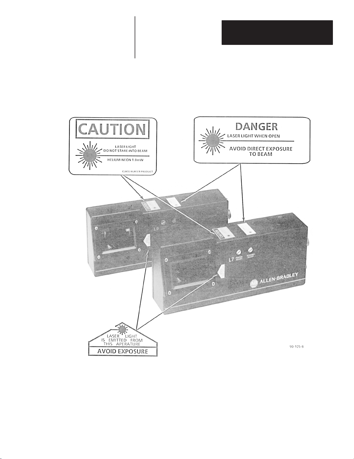
The scan head is labeled in accordance with federal regulations. If any label
is removed, lost, or becomes illegible, order a replacement from your
Allen–Bradley representative. Figure 1.1 shows location of the labels on the
scan head.
WARNING: No user maintenance of the scan head is required.
Do not open the enclosure!
!
WARNING: Improperly controlling, adjusting, or operating the
scan head can result in hazardous radiation exposure.
1–2
Page 7
Chapter 1
Using this Manual
Figure 1.1
Location of Warning and Caution Labels on the Scan Head
1–3
Page 8
Chapter
Chapter Objectives
Overview
A–B
2
Product Description
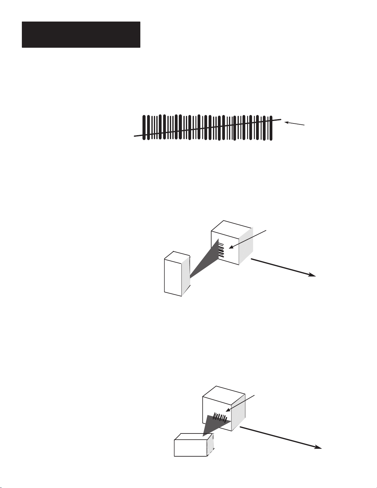
The capabilities of the scan head are described when connected to a Catalog
No. 2755–DM9 Decoder.
The Industrial Medium and High Speed Bar Code Scanners are moving
beam, bar code scan heads designed for use with the Catalog No. 2755–DM9
Decoder. The scanners are available as shown:
• Side scanning (Catalog No. 2755–L7Sx①, –L9Sx①)
• Side Raster scanning (Catalog No. 2755–L7Rx①, –L9Rx①)
① The x stands for the different range selections of each scanner. Refer to Figures 2.2 and 2.3.
Scanning is bidirectional at approximately 350 scans per second with an L7,
Industrial Medium–Speed Bar Code Scanner and 800 scans per second with
an L9, Industrial High–Speed Bar Code Scanner. Depending on the scanner
used, symbols can be scanned as near as 3.5 inches (8.9 cm) and as far as 50
inches (127 cm) away.
Figure 2.1
Side Scanning and Raster Scanning
90–105–9
The side scanning model reflects the scanning beam out of the side of the
NEMA 4 case.
The raster scanning model uses a stepping raster motor to project what
appears to be a number of parallel beams out the side of the unit. This type
of scan head is useful when attempting to scan poor quality labels, or labels
that may not always be in exactly the same place.
2–1
Page 9
Chapter 2
Product Description
L7 Reading Ranges
Figure 2.2 illustrates the average reading ranges, relative to the symbol’s
minimum bar width, that you should expect when using an L7 scanner with
your Catalog No. 2755–DM9 Decoder.
Figure 2.2
Average Scan Range vs. Minimum Bar Width for L7 Scanner
Minimum Bar Width
Mils
Millimeters
50
1.27
45
1.14
40
1.02
35
.89
30
.76
25
.64
20
.51
15
.38
10
.25
5
.13
2755–L7SC
2755–L7RC
2755–L7SD
2755–L7RD
2755–L7SB
2755–L7RB
2755–L7SA
2755–L7RA
2–2
Inches
Centimeters
12.7
① Scan Range will vary with symbol quality, pitch and skew. This application was based on no more than 5 ° pitch and 30° skew, with full scan beam
(Figure 5.3). Refer to Chapter 3, Installation Considerations when reading labels with more than 20° pitch.
10
5
38.1
25.4
Scan Range (from face of scanner)
15
20
50.8
63.5
25
30
76.2
88.9
35
①
40
101.6
114.3
45
50
127.0
The following table compares the minimum bar width to the scan range of
each catalog number.
Minimum Bar
Width
Mils mm Inches Centimeters Side Scanning
7.5
10
20
11
20
25
16
25
35
20
35
50
① When using ‘‘A’’ range scanners to read labels with high paper noise, increasing the skew to 25 will enhance performance.
.19
.25
.51
.28
.51
.64
.41
.64
.89
.51
.89
1.27
Scan Range
6.5 – 8.5
6.0 – 9.0
5.0 – 11.0
8.5 – 13.5
5.5 – 19.0
3.5 – 22.0
10 – 23
8 – 29
6 – 35
16 – 35
8 – 50
8 – 50
① Catalog Number
16.5 – 21.6
15.2 – 22.9
12.7 – 27.9
21.6 – 34.3
14.0 – 48.3
8.9 – 55.9
25.4 – 58.4
20.3 – 73.7
15.2 – 88.9
40.6 – 88.9
20.3 – 127
20.3 – 127
2755–L7SA① 2755–L7RA①
2755–L7SB 2755–L7RB
2755–L7SD 2755–L7RD
2755–L7SC 2755–L7RC
Raster
Scanning
Page 10
Chapter 2
Product Description
L9 Reading Ranges
Figure 2.3 illustrates the average reading ranges, relative to the symbol’s
minimum bar width, that you should expect when using an L9 scanner with
your Catalog No. 2755–DM9 Decoder.
Figure 2.3
Average Scan Range vs. Minimum Bar Width for L9 Scanner
35
.89
30
.76
25
.64
20
.51
15
.38
10
.25
5
.13
2755–L9SD
2755–L9RD
2755–L9SB
2755–L9RB
2755–L9SA
2755–L9RA
Minimum Bar Width
Mils
Millimeters
Inches
Centimeters
① Scan Range will vary with symbol quality, pitch and skew. This application was based on no
more than 5°pitch and 30° skew, with full scan beam (Figure 5.3). Refer to Chapter 3, Installation
Considerations when reading labels with more than 20° pitch.
5
12.7
10
25.4
Scan Range (from face of scanner)
15
38.1
20
50.82563.53076.23588.9
①
The following compares the minimum bar width to the scan range of each
catalog number.
Minimum Bar Width Scan Range② Catalog Number
Mils mm Inches Centimeters
7.5
10
20
11
20
25
16
25
35
② Scan range will vary with symbol quality. This application was based on no more than 5° pitch and 30° skew with
full scan beam (Figure 5.3). Refer to Chapter 3, Installation Considerations when reading labels with more than 20°
pitch.
③ Scan range may be reduced when using low contrast labels.
.19
.25
.51
.28
.51
.64
.41
.64
.89
6.5 – 8.5
6.0 – 9.0
5.0 – 11.0
10 – 13.5
9 – 16
8.5 – 18
10.5 – 21.5
9.0 – 25.5
7.5 – 30③
16.5 – 21.6
15.2 – 22.9
12.7 – 27.9
25.4 – 34.3
22.9 – 40.6
21.6 – 45.7
26.7 – 54.6
22.9 – 64.8
19.1 – 76.2③
Side
Scanning
2755–L9SA① 2755–L9RA①
2755–L9SB 2755–L9RB
2755–L9SD 2755–L9RD
Raster
Scanning
2–3
Page 11
Chapter 2
Product Description
Features
Laser Shut Off – Use this switch to enable/disable the laser beam without
interrupting power. The upward position (ON) enables the laser, the
downward position (OFF) disables the laser beam. The use of this feature is
covered in Chapter 5, Operation.
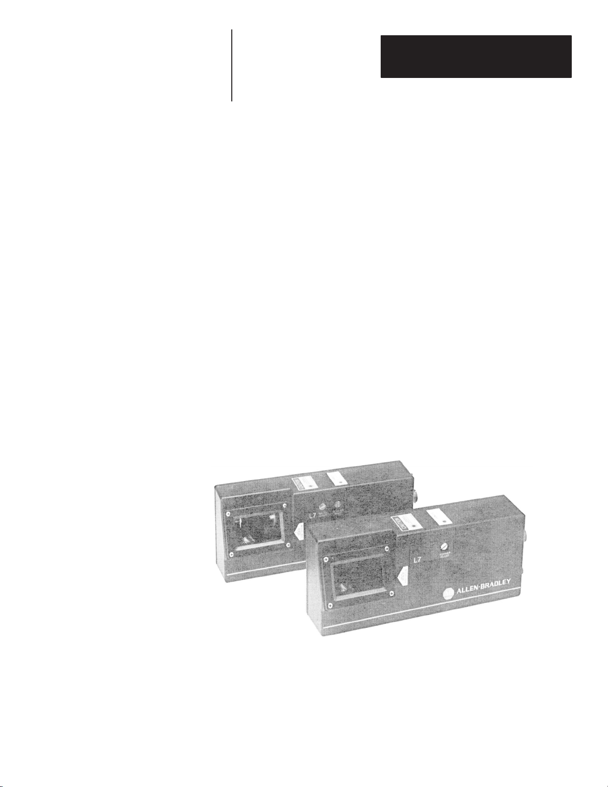
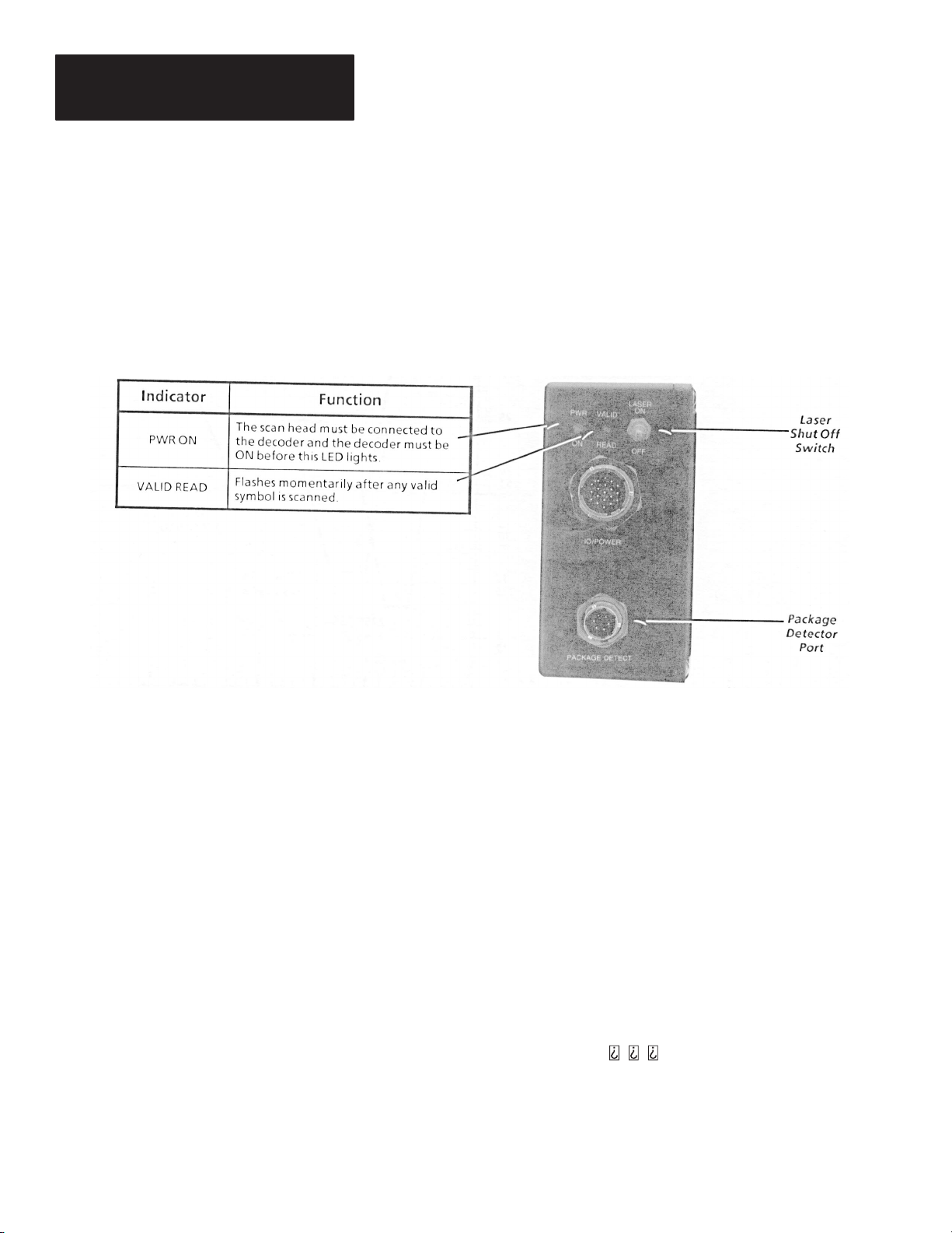
LED indicators – There are two LEDs on the back of the scan head, Power
On and Valid Read. They are defined in Figure 2.4.
Figure 2.4
Scan Head Features
2–4
NEMA 4 Case – Both the L7 and L9 scan heads are housed in gasketed,
NEMA 4, aluminum cases.
Replaceable Scan Windows – You can easily remove and replace the scan
windows. Both the L7 and L9 scan heads are shipped with coated, optical
quality, glass windows. Coated, low loss, optical quality, plastic windows
are also available for special applications, or when required by FDA
regulations. The use of this feature is covered in Chapter 6, Maintenance
and Troubleshooting.
Package Detector Port – Connect the optional Package Detector Assembly
(Catalog No. 2755–NP3, or NP5) to this port to allow the scan head to be
turned on only when there is a package present.
The use of this feature is
covered in Chapter 4, Installation.
Scan Width Adjustment – This four position switch is located behind a
gasketed 1/4–20 screw. Rotate this switch, using the supplied tool, to set the
scan width to one of four settings: full,
, , .
Examples of this feature are
covered in Chapter 5, Operation.
Raster Height Adjustment – This four position switch is located behind a
gasketed 1/4–20 screw. Rotate this four position switch to increase/decrease
the height of your raster scanning pattern (on L7R and L9R only). Examples
of this feature are covered in Chapter 5, Operation.
Page 12
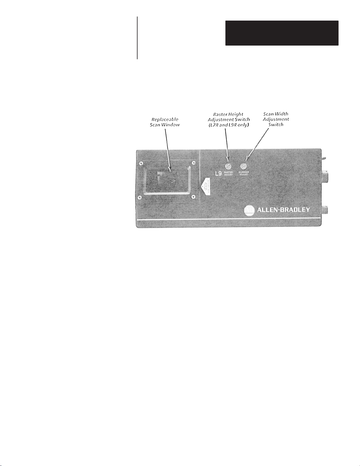
Figure 2.5
Scan Head Features
Chapter 2
Product Description
Cabling
Accessories
Scanner to Decoder cables are sold separately. Refer to Table 2.C for
information necessary to order the proper cable.
Several accessories are available to provide installation and operational
flexibility, including:
• Package Detector Assembly – This assembly consists of a Package
Detector Switch and a reflector. This switch indicates to the decoder that
a package is present.
• Mounting hardware – A swivel ball mounting base is available for use
with a flat mounting plate or “T” Mounting plate.
• Replaceable Windows – Replaceable, optical quality, glass and plastic
windows are available.
2–5
Page 13

Chapter 2
Product Description
The following table lists system accessories.
Catalog
Number
2755–NP3
2755–NP5
2755–NC9
Long Range Package
Detector Assembly
Short Range Package
Detector Assembly
Package Detector Port
Connector
2755–NM1 Swivel Mounting Base
Item Description
An infrared photoelectric switch and reflector. For the
detection of packages up to a maximum of 18 feet
(5.5 m) away.
A visible red photoelectric switch and reflector. For the
detection of packages up to a maximum 10 feet (3 m) away.
Connects user–supplied photoelectric switch to scan head.
Accepts cables with .190 to .312 inches
(4.8 to 7.9 mm) outer jacket diameter.
Universal swivel ball mount for greater installation flexibility.
Must be used with “T” Mounting Plate or Flat Mounting Plate.
2755–NM2 “T” Mounting Plate
Mounts Swivel Mounting Base (Catalog No. 2755–NM1) to
scan head.
Attach this plate to scan head in order to use your own
2755–NM3 Flat Mounting Plate
brackets, or to use the Swivel Mounting Base (Catalog No.
2755–NM1) when you want the swivel ball close to the base
of the scan head.
2755–CL10 10 foot (3 meter) Cable Connects scanner to Catalog No. 2755–DM9 Decoder.
2755–CL25 25 foot (7.6 meter) Cable Connects scanner to Catalog No. 2755–DM9 Decoder.
W77121–800–01①
W77121–800–02①
W77121–802–01①
W77121–802–02①
① Replacement part number.
2–6
Replacement Glass
Window Kit
Replacement Plastic
Window Kit
Caution & Warning Label
Kit (English Only)
Caution & Warning Label
Kit (Alternate Language)
Anti–reflective, optical glass replacement window.
Hard coated, anti–reflective, optical quality, plastic
replacement window.
2755–L7, L9 - 5 sets per package.
2755–L7, L9 - 1 set each in German, French, Italian,
Spanish.
Page 14
Chapter
Chapter Objectives
How thw Scan Head Operates
A–B
3
Installation Considerations
The operation of the scan head is briefly described. In addition, the
importance of proper symbol positioning and the effect pitch has upon a
symbol is also discussed.
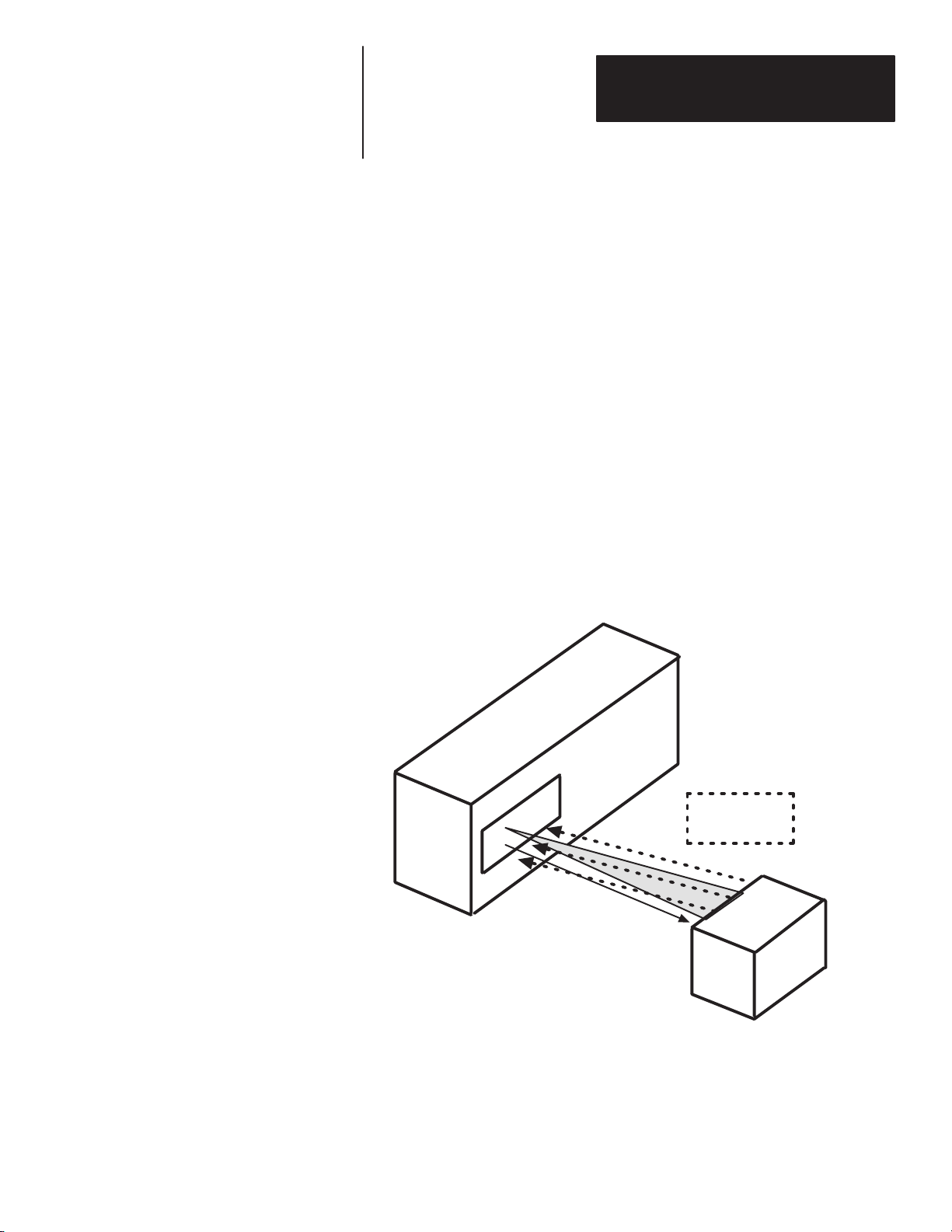
Inside the scan head is the laser, the lens and mirror system and the
electronics. The laser generates a small, concentrated light beam that is
focused and projected through a window. This light is reflected by a symbol
and returned to the scan head for processing. The signal is then sent to the
decoder for further processing. Refer to Figure 3.1.
Figure 3.1
How the Scan Head Operates
T o Label
Reflected light
from symbol
(Diffuse Return)
3–1
Page 15
Chapter 3
Installation Considerations
Positioning the Symbols Correctly
As the symbols move past the scan head, they must be correctly oriented.
The laser’s line of light must cut through all the bars and spaces in one
sweep.
Laser’s line of light
cuts through the
entire symbol
For example, if the scan head is mounted so the laser beam is in the vertical
direction, then the symbol must also be mounted vertically, commonly
known as the step ladder orientation. Figure 3.2 illustrates the step ladder
orientation.
Figure 3.2
Step Ladder Orientation
Label
Conveyor
Direction
3–2
If the scan head is mounted so the beam is in the horizontal direction, the
symbol must also be in the horizontal direction. This is termed picket fence
orientation.
Refer to Figure 3.3 for an example of the scan head and symbol in a picket
fence orientation.
Figure 3.3
Picket Fence Orientation
Label
Conveyor
Direction
Page 16
Chapter 3
Installation Considerations
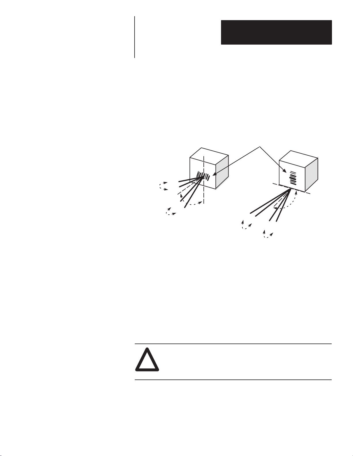
When setting up your scanner, you should attempt to have the laser line of
light nearly perpendicular to the bars and spaces of the symbol. For optimal
performance mount the scan head in a skewed position, 10° to 20° angle off
normal from the symbol, as shown in Figure 3.4.
Figure 3.4
Proper Mounting of Scan Head
Symbol
20°
10
°
Optimal angles
for scanning
beam
10°
20°
90°
20
90°
°
10°
10°
20°
Optimal angles for scanning
beam
The scan head can successfully decode symbols that are out of alignment,
provided that the projected, or apparent, bar element widths are within the
minimum widths shown in Tables 2.A and 2.B.
Symbols that are pitched or tilted up to ±45°, are still readable. Skewed
symbols can also be read as long as the misalignment is less than ±50°.
Figure 3.5 shows a correctly placed symbol as well as misaligned symbols.
Note: When using “A” range scanners to read labels with high paper noise,
increasing the skew to 25° will enhance performance.
WARNING: If at any time during operation an intense dot of
light is reflected onto a symbol instead of a line of light, turn the
!
scanner OFF with the toggle switch on the back of the scanner.
Then turn the decoder OFF.
3–3
Page 17

Chapter 3
Installation Considerations
Figure 3.5
Positioning Terminology
Skewed package
and symbol
Pitched package
and symbol
Tilted, over square
symbol
Correctly positioned
symbol and package
3–4
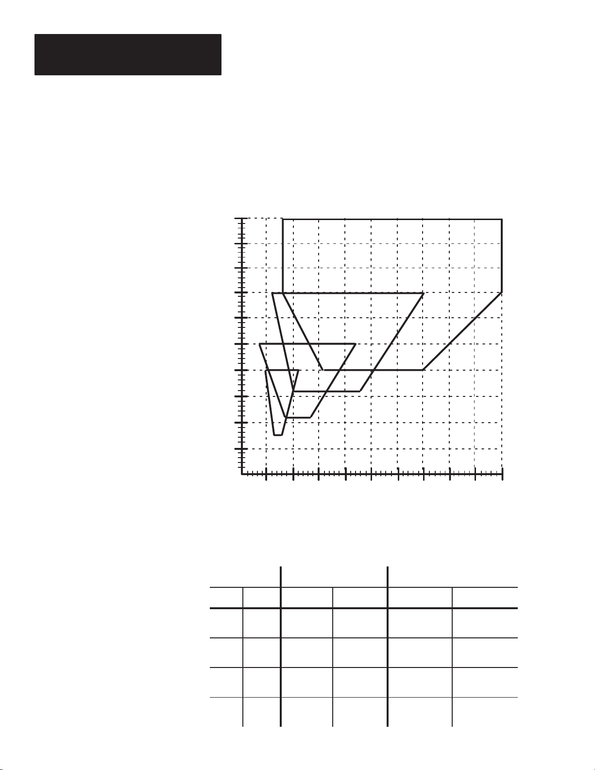
When setting up a raster scanner, the raster pattern can either overlap the
entire symbol, or be restricted to cover only a portion of the symbol.
Overlapping the symbol helps to aid in the scanning of misaligned symbols.
Restricting, or dithering the raster pattern is helpful when scanning symbols
of poor quality. Refer to Figure 3.6.
Figure 3.6
Raster pattern
Page 18

Chapter 3
Installation Considerations
Usable Beam Length
To estimate the Usable Beam
Width:
1. Determine the distance from
the face of the scanner to the
center of the bar code symbol.
This distance is your Reading
Distance.
2. Locate your Reading
Distance on the L7 or L9
diagram (the Reading
Distances are displayed across
the top of each scale).
3. Displayed across the bottom
of each scale are the nominal
Usable Beam Lengths.
Figure 3.7 shows the size and shape of the scanning window. The black area
is a no read are area.
The Usable Beam Length (bottom of chart) is compared to the the Reading
Distance (top of chart). The Usable Beam Length is slightly less than the
projected beam length. The reading distance is measured from the scan
window to the center of the symbol.
Figure 7
Usable Beam Length
5
0
Inches
Centimeters
Inches
Centimeters
12.71025.41538.12050.82563.53076.23588.9
0
5.2
NA
13.2
NA
Inches
Centimeters
8.7
22.1
0
0
L7 Reading Distance
Reading Distance
12.2
15.6
19.1
31.0
39.6
48.5
22.6
57.4
26.1
66.3
①
40
101.645114.3
29.6
75.2
Usable Beam Length (nominal)
L9 Reading Distance
12.7
5
10
25.4
38.1
①
15
20
50.82563.53076.2
33.0
83.8
50
127.0
36.5
92.7
Usable
Beam
Length
Inches
Centimeters
NA
NA
2.9
7.4
4.8
12.2
Reading Distance
6.7
17.0
8.6
21.8
10.6
26.9
12.5
31.8
Usable
Beam
Length
Usable Beam Length (nominal)
① Measured from the face of the scanner to the center of bar code symbol.
3–5
Page 19

Chapter 3
Installation Considerations
Compensating for Pitched Symbols
When attempting to read a symbol that is pitched, two things must be
considered:
• The adjusted minimum bar width
• The nearest and farthest code elements must be within the scanners
reading range
Minimum Bar with Adjustment
When a symbol is pitched, the bars appear to be narrowerand closer to one
another. This apparent element width is a reduction of the actual element
width. Before you attempt to position your scanner using Figures 2.2 and 2.3
found in Chapter 2, you must determine your symbol’s adjusted minimum
bar width.
Figure 3.8 shows two boxes, each having the same bar code symbol printed
on them. Below each box is an exaggerated view of 5 elements (3 black, 2
white) as seen from the top down.
Figure 3.8
Actual versus Apparent Element Width
Actual Element Width 21 mil (.53
mm) 0° pitch
Apparent Element Width 18mil (.46
mm) because of 30 ° pitch, elements
appear narrower
3–6
Actual Element Widths
21 mil
Pitched 30
30°
°
Actual Element Widths
21 mil
Apparent Element Widths
18 mil
Page 20

Chapter 3
Installation Considerations
For example, a 21 mil (.53mm) symbol with 0° pitch can be successfully
scanned at 27 inches (68.6 cm) with a Catalog. No. 2755–L7SC scanner. If
you pitch the symbol 30° and determine the adjusted minimum bar width
using the formula below, you will realize that you are attempting to read an
18 mil (.46 mm) symbol.
Adjusted Minimum Bar Width = Actual Bar Width * cos [pitch angle]
In our example, the following conditions apply:
Actual Bar Width = 21 mil (.53 mm)
Pitch Angle = 30°
Minimum Bar Width
Inches
Millimeters
25
.64
20
.51
15
.38
10
.25
5
.13
Therefore: 21
cos [30] = 18.2 mil (.46 mm)
*
The minimum recommended bar width that the L7SC can read is 20 mil (.54
mm). Because of the pitch of the symbol, you will have to use a different
scanner, such as the L7SD. However, you will also have to decrease the
distance between the scanner and the symbol. The Catalog No.
2755–L7SD’s maximum read range with a 18 mil (.46 mm) symbol is 24
inches (61 cm). The farthest element of the symbol including the quiet zone
must not exceed 24 inches (61 cm).
In summary, increasing the pitch of the symbol decreases the minimum bar
width. Figure 3.9 is an excerpt from Figure 2.2, which illustrates this
example.
Figure 3.9
Pitch Effecting Scan Range
2755–L7SC
2755–L7SD
2755–L7SB
2755–L7SA
21 mil (.53mm) long
symbol with 0° pitch
21 mil (.53mm) long
symbol with 30°
pitch yields adjusted
minimum bar width
of 18 mil (.46mm).
Symbol to scanner
distance has also
been compensated so
symbol can be read
(see next page).
Inches
Centimeters
5
12.7
10
25.4
15
38.1
Scan Range ( from scan window)
20
50.82563.53076.23588.9
3–7
Page 21

Chapter 3
Installation Considerations
Code Elelment Distance
The pitched symbol’s nearest and farthest elements must be within the
minimum and maximum reading distance of your scanner.
Centering your symbol within the scanner’s minimum and maximum scan
range can help guard against pitched symbols exceeding the scan range
limits. However , you could exceed the scan range with a pitched symbol, as
shown in Figures 3.10 and 3.11.
Figure 3.10
Scan Range and Symbol Resolution at 0° Pitch
3” (7.6 cm) long
symbol pitched 0°.
The center of the
symbol is positioned
10” (25.4 cm) from the
face of the scanner.
Scan Range equals
10” (25.4cm).
2755–L7SA
10 ”
3 ”
Symbol’s Nearest and
Farthest Elements
10”
Minimum Bar Width
Mils
Millimeters
25
.64
20
.51
15
.38
10
.25
5
.13
Centimeters
Inches
5
12.7
2755–L7SD
2755–L7SB
2755–L7SA
10
25.4
Scan Range (from face of scanner)
15
38.1
20
50.82563.53076.23588.9
2755–L7SC
The center of the 3”
(7.6 cm) long symbol,
pitched 0°, is
positioned 10” (25.4
cm) from the face of
the scanner.
As you can see, the
2755–L7SA scanner
can be effectively
used for this
application.
3–8
Page 22

2755–L7SA
Chapter 3
Installation Considerations
Figure 3.11 further illustrates how the pitched symbol changed the Scan
Range enough to require a different scanner.
Figure 3.11
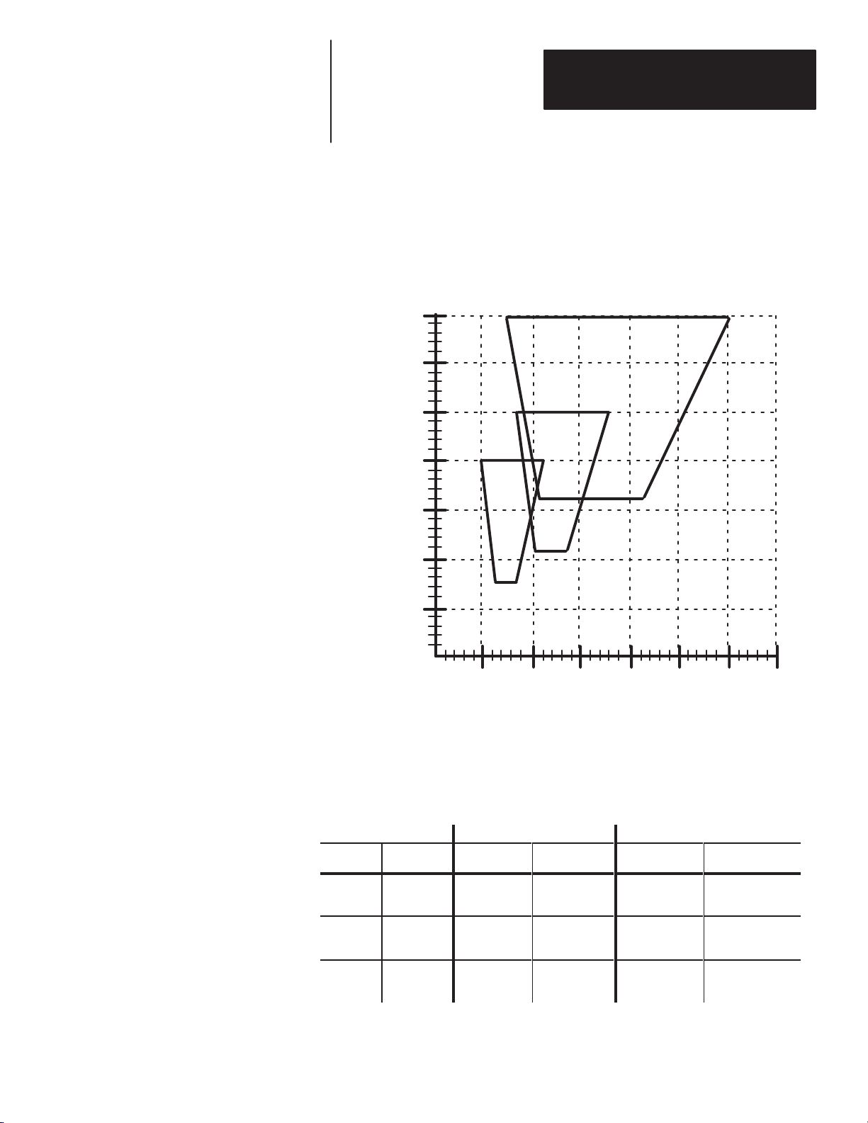
Scan Range And Symbol Resolution Changed By Pitch
11.5 ”
10 ”
3 ”
In this example, a 3
inch (7.6 cm) symbol
pitched 30° will
require the scanning
beam to extend an
additional 1.5 inches
(3.8 cm).
Minimum Bar Width
Mils
Millimeters
25
.64
20
.51
15
.38
10
.25
5
.13
Centimeters
Inches
5
12.7
2755–L7SB
2755–L7SA
10
25.4
Scan Range (from face of scanner)
15
38.1
20
50.82563.53076.23588.9
1.5 ”
Symbol’s
Nearest
Element
10”
2755–L7SC
2755–L7SD
Symbol’s
Farthest
Element
11.5”
This was the the
Scan Range and
element width at 0°
pitch.
This is the new Scan
Range.
Pitching the symbol
changed the bar
width and extended
the scan range.
The L7SA scanner is
not recommended for
this application.
Instead, use the
L7SB.
A pitched symbol will always change the minimum bar width and scan range
of the symbol. The amount of the change depends on the pitch of the
symbol.
3–9
Page 23

Chapter
W
Chapter Objectives
arning and Cautions
A–B
4
Installation
Carefully read this chapter before installing the system. We list rules and
recommendations for installing and connecting your scanner.
• WARNING: Do not make any other adjustments to the
equipment than those specified in this manual.
!
• WARNING: If at any time during operation an intense dot
of light is generated instead of a thin line of light,immediately
turn the laser off, using the toggle switch on the back of the
scanner, then remove power to the decoder.
Before You Start
Tools You Will Need
CAUTION: Do not look directly into the laser beam. It could
damage your eyes.
WARNING: No user maintenance of the hardware is required.
!
The angle and distance between the scan head and the label is an important
consideration. These considerations, orientation and alignment, are
described in Chapter 3, Installation Considerations.
Normally, the only tools you will need for installation will be the adjustment
tool supplied with your scanner. If the optional Swivel Mounting Base and
Plate are used (Catalog No. 2755–NM1 and 2755–NM2), you will also need
a screwdriver and a
Do not open the unit’s housing!
3
/16–inch Allen wrench.
4–1
Page 24

Chapter 4
Installation
Determining the Space Requirements
10–32UNF–2B
x .31
4.75 in
12.07 cm
Back View
3.00 in
7.62 cm
The decoder and scan head are separate units that can be mounted in different
locations. A 10 foot (3 meter) or 25 foot (7.6 meter) cable is used to connect
the two units. Figure 4.1 illustrates the dimensions of the scan head.
Figure 4.1
Mounting Dimensions of the Scan Head
2.69 in
6.83 cm
5.38 in
13.67 cm
2.69 in
6.83 cm
4.75 in
12.07 cm
3.19 in
8.05 cm
2.69 in
6.83 cm
2.20 in
5.59 cm
4.75 in
12.07 cm
Front View
3.00 in
7.62 cm
12.5 in
31.75 cm
Bottom View
10–32UNF–2B
x .31
1.357 in
3.45 cm
1.33 in
3.38 cm
4.75 in
12.07 cm
Mounting the Scan Head
4–2
Before installing the scan head, review the following information:
• Determine the optimum position of the scan head relative to the labels
that are to be read. Refer to Chapter 3 for positioning information.
• If you are using the optional swivel base or brackets, add their dimensions
into your positioning calculations.
• Allow a minimum clearance of 8 inches (20.3 cm) at the rear of the scan
head so you can attach the cables to the various ports.
• Securely mount the scan head to a rigid surface to ensure proper operation
of the scanning mechanism.
The thickness of your mounting surface determines the length of the screws
or bolts required. You will need two 10–32 screws, with flat and split
washers. Select a length that equals the thickness of the mounting surface,
thickness of the washers plus the depth of the screw holes,
mm).
3
/8–inch (9.5
Page 25

V
ibration Cautions
Chapter 4
Installation
The raster scanning models may occasionally experience raster rollover.
This condition is caused by jarring the scanner, excessive vibration, and will
occasionally occur upon power up.
The stepping of the raster motor is controlled by an incremental shaft
encoder, which has the ability to reset itself if one of the above conditions is
met.
Note: If the scanner is jarred during operation, labels may not be
scanned while the raster is resetting. In high speed operations, some
objects may not be scanned.
4–3
Page 26

Chapter 4
Installation
How to Install the Swivel
Mounting Base (Catalog No.
2755-NM1 and 2755-NM2)
3.19 (8.10)
2.812 (7.14)
2.00
1.625
(5.08)
(4.13)
.187
(4.75)
7/16–20
UNF–2A
For greater installation flexibility, you can attach the scan head to an optional
Swivel Mounting Base. The installation dimensions of the Swivel Base and
its associated “T” Mounting Plate are shown in Figure
4.2.
Figure 4.2
Mounting Dimensions of Swivel and “T” Mounting Plate
Inches (Centimeters)
.75
(19.05)
3.63
(9.22)
3.75
(9.53)
1.500
(3.81)
.180 (4.57)
4 places
.19 (4.83)
1.88 (4.78)
.30 (7.62)
1.00
(2.54)
5.50
(13.97)
.25
(6.35)
3.000
(7.62)
0.213 Dia.
2 Holes
1.50 (38.1)
.38 (9.65)
1.25 (3.18)
1.00 (2.54)
7/16–20 UNF–2B
5/8 Deep
.13 (3.3)
Swivel Mounting Base Catalog No. 2755–NM1
“T” Mounting Plate Catalog No. 2755–NM2
4–4
Page 27

Chapter 4
Installation
Using the Flat Mounting Plate
(Catlaog No. 2755-NM3 Series B)
A Flat Mounting Plate is also available. By attaching this plate to the bottom
of your scan head, you can position the swivel mounting ball close to the
base of the scan head. Make sure the Allen nut on the mounting ball is tight.
You may also use the Flat Mounting Plate when you want to mount the scan
head with brackets of your own design. Whenever possible, mount the
scanner on its wide side as shown on page 4–3. The dimensions are shown
in Figure 4.3.
Figure 4.3
Mounting Dimensions of the Flat Plate Inches (Centimeters)
2.25 (5.71)
.38 (0.96)
3.000
(7.62)
2.812
3.50
(8.89)
.25 (0.64)
Flat Mounting Plate with Mounting Screws Catalog No. 2755–NM3 Series B
(7.14)
.093 (0.24)
.31 (0.79)
1.500 (3.31)
.750
(1.91)
1.625
(4.13)
0.204 (0.52)
& Countersunk
80
°
0.390 (0.99)
2 Places
6–32
UNC–2B
4 Places
.25
(0.64)
Connecting Your Equipment
Connect your equipment using the appropriate cables. Follow the
step–by–step procedure described below.
Step 1 With the power to the decoder OFF, connect your scanner to the port
labeled Scan Head on the back of the decoder.
Step 2 Connect the configuration terminal to the decoder’s Auxiliary port.
Step 3 The initial configuration should be done at this time, if it was not
done earlier (refer to the User’s Manual supplied with your decoder).
Step 4 If a host computer will be used, connect it to the port labeled Host on
your DM9 decoder.
Step 5 If output devices will be used, connect them to the decoder (refer to
the User’s Manual supplied with your decoder).
Step 6 If a package detector will be used, connect it to the small port on the
scan head.
Step 7 Refer to Chapter 5 for scanner operation.
4–5
Page 28

Chapter 4
Installation
Installing the Package Detector Assembly
When installing the Package Detector Assembly, we recommend you observe
the following guidelines:
• Install the Package Detector Switch at an angle to the label to minimize
the light reflecting off the label.
• Install the reflector so the Package Detector’s operating range is not
exceeded.
• The Package Detector’s beam must be broken before the label is in
position.
Figure 4.4
Recommended Placement of Package Detector Switch and Reflector.
Reflector①
4–6
Scan Head
The laser beam must not strike the reflector, or you may get inaccurate reads
①
Package Detector
Switch
Figure 4.5 specifies which pins on the Package Detector Port Connector
(Catalog No. 2755–NC9) are used.
Figure 4.5
Pins Used on Package Detector Connector
Package Detector Input ①
A
Common
B
+ 12V
C
Package
Detector Port
① The package detector input is used to trigger the decoder to start decoding information. The package detect LED
on the Decoder will light when the package detect input is active.
Note: If you have programmed the decoder to turn the laser ON only upon a
package detect, the laser will be OFF until the package detector is triggered.
Refer to the User’s Manual for your decoder.
Page 29

Chapter
W
Chapter Objectives
arning and Cautions
A–B
5
Operation
Guidelines on how to operate the scanners are described when connected to a
Catalog Number 2755-DM9 Decoder.
• WARNING: Do not make any other adjustments to the
equipment than those specified in this manual.
!
• WARNING: If at any time during operation an intense dot
of light is generated instead of a thin line of light,immediately
turn the laser off, using the toggle switch on the back of the
scanner, then remove power to the decoder.
CAUTION: Do not look directly into the laser beam. It could
damage your eyes.
Laser On/Off Control
As shown in Figure 5.1, a toggle switch is used to enable and disable the
laser beam that exits the enclosure.
Figure 5.1
Laser On/Off Toggle Switch
5–1
Page 30

Chapter 5
Operation
Scan Width Adjustment
As shown in Figure 5.2, all scan heads come equipped with a 4 position
switch used for scan width adjustment. The switch is covered by a gasketed
1/4–20 screw.
Figure 5.2
Scan Width Adjustment Switch
To avoid an unnecessarily long beam, rotate this switch clockwise. The scan
width will reduce from full to approximately 3/4, 1/2 and 1/4. Figure 5.3
shows the scan width relative to the switch position. In each case, the usable
scan beam will be 80% of the actual beam width.
Figure 5.3
Scan Width Adjustment Switch Positions
5–2
Full scan beam
1/2
scan beam
3/4 scan beam
Factory Setting
1/4 scan beam
Reducing the scan width will often improve the scanner’s performance while
reading UPC, Code 128 and other high density labels at short ranges.
Increasing the scan width may improve the readability of low contrast labels
at maximum ranges.
Page 31

Chapter 5
Operation
Scan Width Adjustment Procedure
Raster Head Adjustment
1. Remove power to the scan head. In doing so, you will avoid harmful
direct eye contact with the beam.
2. Remove the gasketed 1/4–20 screw to expose the scan width
adjustment screw.
3. Using the adjustment tool provided with the scanner, carefully rotate
the switch to the desired position.
4. Replace the gasketed 1/4–20 screw.
5. Apply power to the scan head.
Raster scan heads are equipped with stepping raster motors designed to move
in synchronization with the scan sweep. The raster motor takes one step on
each reverse scan. Each step deflects the scan beam by approximately .3°.
The approximate spacing between the raster lines can be expressed as:
N (Lines/Inch) = 191/D
D = Distance from scan head to Label. For maximum accuracy,
measure from the label center to the scan window, then add
1.28 inches (3.25 cm).
Figure 5.4 shows the Raster Height Adjustment Switch, which is covered by a
gasketed 1/4–20 screw.
Figure 5.4
Raster Height Adjustment Switch
5–3
Page 32

Chapter 5
Operation
This switch selects the number of steps, or increments, the raster motor
makes. To reduce the number of steps, rotate this switch counterclockwise.
The raster heights are shown, relative to the switch positions, in Figure 5.4.
Figure 5.4
Raster Height Adjustment Switch Positions
Raster Height Adjustment Procedure
30° Raster Sweep
8° Raster Sweep
15° Raster Sweep
3° Raster Sweep
Factory Setting
1. Remove power to the scan head. In doing so, you will avoid harmful
direct eye contact with the beam and scanner rollover (explained on
page 4–3 under Vibration Cautions).
2. Remove the gasketed 1/4–20 screw to expose the Raster Height
Adjustment Switch.
5–4
3. Using the adjustment tool provided with the scanner, carefully rotate
the switch to the desired position.
4. Replace the gasketed 1/4–20 screw.
5. Apply power to the scan head.
Page 33

Chapter
Eq
Chapter Objectives
Maintaining the
Scan Window Removal
uipment
A–B
6
Maintenance and Troubleshooting
Maintenance procedures are stated and troubleshooting charts are provided in
this chapter.
WARNING: No user maintenance of the scan head is required.
Do not open the enclosure.
!
The scan window fits into an opening on the side of the scan head. A
gasketed cover is then tightly secured over the window to ensure a NEMA 4
rating.
To remove the scan window:
1. Remove the four Phillips head screws from the cover.
2.Lift the cover away from the scan head. Make sure the scan window does
not fall out. Handle the scan window by the edges to avoid finger prints.
Refer to Figure 6.1.
Figure 6.1
Scan Window Removal
6–1
Page 34

Chapter 6
Maintenance and Troubleshooting
Cleaning the Glass Window
Do not use abrasive materials, such as disposable paperwipes, to clean the
glass scan window. Most disposable wipes, or paper towels, use glass fibers
which will scratch and cloud the window. Instead, use the following
materials:
Air: Optics rated clean air
Solvent: Optics rated cleaning solution for use on coated lenses
Wipe: Optics quality lens cleaning paper and cotton–tipped swabs.
Use the following procedure to clean the glass scan window:
CAUTION: Do not use abrasive materials, such as disposable
paper wipes, to clean the glass scan window. In most cases, they
!
contain glass fibers that will scratch and cloud the window.
Step 1 Turn the decoder OFF.
Step 2 Check that the PWR ON indicators on both the decoder and scan head
are OFF.
Step 3 Use the lens cleaning paper to wipe any dust or foreign material from
the window. Be careful not to scratch the window with any grit that might be
on the window.
Step 4 Dust off the scan window and adjacent areas with optics rated air.
Step 5 Remove the scan window. Figure 6.1 illustrates the removal.
CAUTION: Do not touch the internal mirrors! Smudge from
finger prints will diffuse the beam.
!
Step 6 Clean the window using the optics rated cleaning solution,
cotton–tipped swabs and lens cleaning paper. To avoid smearing film and
fingerprints, rotate the cotton–tipped swab, while it’s on the glass, nearly one
full turn. Then, discard it.
Step 7 Replace the scan window.
Step 8 Turn the decoder ON. The PWR ON indicators on both the decoder
and scan head should be ON.
6–2
When the window is clean, you will barely be able to see the reflection of the
laser beam on the clear glass.
Page 35

Chapter 6
Maintenance and Troubleshooting
Cleaning the Plastic Window
Do not use abrasive materials, such as disposable paper wipes, to clean the
plastic scan window. Most disposable wipes, or paper towels, use glass
fibers which will scratch and cloud the window. Instead, use the following
materials:
Air: Optics rated clean air
Solvent: Optics rated cleaning solution for use on coated lenses
Wipe: Optics quality lens cleaning paper and cotton–tipped swabs.
Use the following procedure to clean the glass scan window:
CAUTION: Do not use organic solvents or abrasive materials,
such as disposable paper wipes, to clean the plastic scan window.
!
In most cases, they contain glass fibers that will scratch and cloud
the window.
Step 1 Turn the decoder OFF.
Step 2 Check that the PWR ON indicators on both the decoder and scan head
are OFF.
Step 3 Use the lens cleaning paper to wipe any dust or foreign material from
the window. Be careful not to scratch the window with any grit that might be
on the window.
Step 4 Dust off the scan window and adjacent areas with optics rated air.
Step 5 Remove the scan window. Figure 6.1 illustrates the removal.
CAUTION: Do not touch the internal mirrors! Smudge from
finger prints will diffuse the beam.
!
Step 6 Clean the window using the optics rated cleaning solution,
cotton–tipped swabs and lens cleaning paper. To avoid smearing film and
fingerprints, rotate the cotton–tipped swab, while it’s on the glass, nearly one
full turn. Then, discard it.
Step 7 Replace the scan window.
Step 8 Turn the decoder ON. The PWR ON indicators on both the decoder
and scan head should be ON.
When the window is clean, you will barely be able to see the reflection of the
laser beam on the clear glass.
6–3
Page 36

Chapter 6
Maintenance and Troubleshooting
Troubleshooting the System
Problem Probable Cause Possible Solution
PWR ON indicators on
both scan head and
decoder do not light.
PWR ON indicator on
scan head does not light,
but PWR ON indicator on
decoder is lit.
No laser beam emitted
from window of scan head
Decoder is not turned ON.
Improper connection to power supply.
Line fuse on decoder is blown.
Faulty power cord or switch.
No incoming power.
Interconnect cable between decoder and
scan head is loose.
Interconnect cable is defective.
Scan head or decoder is defective.
Laser ON/OFF toggle switch is in OFF
position.
No scan trigger signal.
Improperly positioned labels.
Turn decoder ON.
Reconnect power cord to source.
Replace fuse on decoder.
Check that voltage is present at service
outlet.
Check that voltage is present at service
outlet.
Reconnect cable and check connections.
Replace cable.
Replace scan head.
Check Laser ON/OFF toggle switch
position.
Verify sending of scan trigger by either
package detect or trigger from decoder.
Check that reading distance is correct and
orientation of labels to scan head is correct.
Unable to read a label.
Laser beam expands and
contracts.
Warning!
Laser beam is an intense
dot of light.
6–4
Poor quality labels.
Laser ON/OFF toggle switch is in OFF
position.
Decoder is improperly programmed.
Loose cables or connections.
Scan Window is dirty
Scan head is not securely mounted. Improve mounting.
Laser scanning mechanism is not operating
correctly.
Check that labels are good quality and
within specifications.
Check Laser ON/OFF toggle switch
position.
Refer to the appropriate User’s Manual.
Check cables and connections.
Clean window . Refer to Chapter 6
Turn laser OFF using toggle switch on back
of scanner, then turn decoder OFF.
Page 37

Chapter
Scan Head
(Catalog Number 2755-L7 and L9
10–32UNF–2B
x .31
A–B
7
Specifications
Electrical Receives power from decoder.
Mechanical
Enclosure Cast aluminum NEMA 4
LED Indicators Power On
Valid Read
Weight 6.5 lbs. (2.95 kg)
Dimensions (H x W x D) 5.38” x 12.5” x 2.69”
2.69 in
6.83 cm
5.38 in
13.67 cm
2.69 in
6.83 cm
4.75 in
12.07 cm
Back View
3.00 in
7.62 cm
4.75 in
12.07 cm
3.19 in
8.05 cm
2.69 in
6.83 cm
2.20 in
5.59 cm
4.75 in
12.07 cm
Front View
3.00 in
7.62 cm
12.5 in
31.75 cm
10–32UNF–2B
x .31
1.357 in
3.45 cm
1.33 in
3.38 cm
4.75 in
12.07 cm
Bottom View
Environment Ambient temperature range, 32° to 131°F (0°
to 55°C)
CDRH Standards Meets Class II standards
7–1
Page 38

Chapter 7
Specifications
Optical
Light Source Focused helium–neon (He–Ne) laser
(632.8nm)
Power 1.5 mW max.
Fixed Scan Rate L7 – 350 scans/second, ± 5%
L9 – 800 scans/second, ± 5%
Scan sweep angle L7 47°
L9 27°
Scan Range L7 3.5” to 50” (8.89 cm to 127 cm) from
scan window. ①
L9 5” to 30” (12.7 cm to 76.2 cm) from
scan window ①
Depth of Field L7 3.5” to 50” (8.89 cm to 127 cm) from
scan window ①
L9 5” to 30” (12.7 cm to 76.2 cm) from
scan window ①
Label Skew L7 5° to 50° from normal ②
L9 5° to 50° from normal ②
Label Pitch L7 5° to 45° from normal ②
L9 5° to 45° from normal ②
Package Detect
Min. OFF–State Voltage 11 VDC
Max.
ON–State Voltage 2 VDC
Depending on the model selected
①
② Depending on label quality
7–2
Page 39

Glossary
A–B
A
AIM
Acronym for Automatic Identification Manufacturers.
alignment
The relative position of a scanner or light source to the target or the receiving
element.
alphanumeric or alphameric
The character set which contains letters, digits, and other characters such as
punctuation marks.
aspect ratio
The ratio of height to width of a bar code symbol. A code twice as high as
wide would have an aspect ratio of 2; a code twice as wide as high would
have an aspect ratio of
attended system
A scanner/decoder combination that must be activated, or attended, by an
operator.
or 0.5.
G
average background reflectance
Expressed as a percent, this is the simple arithmetic average of the
background reflection reading from at least five different points on a sheet.
average edge
An imaginary line bisecting the irregularities of the character edge.
B
background
The area surrounding a printed symbol.
bar
The dark element of a printed symbol.
bar code
The vertical bars and spaces found in a bar code symbol.
bar code density
The number of characters which can be represented in a lineal inch.
bar code label
A label that carries a bar code and is suitable to be affixed to an article.
bar code reader
A device used to identify and read a bar code symbol. Also know as a
decoder
bar code symbol
A group of vertical bars ,that represents a character or group of characters
whose spacing is determined by a specific set of rules. In most cases, human
readable characters are also printed below the bars.
G–1
Page 40

Glossary
bar length
The bar dimension perpendicular to the bar width.
bar width
The thickness of a bar measured from the edge closest to the symbol’s start
character to the trailing edge of the same bar.
bidirectional symbol
A bar code symbol that can be read in complementary (two) directions.
binary code
A power–of–two code; each bit position has a weighted value.
bit
An acronym for Binary Digit. The smallest unit of information in the binary
numbering system. Represented by the digits 0 and 1.
C
CCD
Acronym for Charge Couple Device; a linear image sensor that scans at high
speeds (approximately 4,000 times per second) and detects the presence or
absence of marks passing under the device.
character
A single group of bars and spaces representing an individual number, letter
or punctuation mark. A graphic shape representing a letter, number or
symbol.
character alignment
The vertical or horizontal position of characters with respect to a given
reference line.
character density
The dimension, in linear inches, required to encode one character.
character reading
Reading of alpha or numeric characters,and/or symbols, by optical means.
character set
Those characters available for encoding purposes.
G–2
character skew
See skew.
character spacing
The horizontal distance between two adjacent characters.
check digit
A digit included within a symbol whose value is based mathematically on
other characters included in the symbol. It is used to mathematically check
the accuracy of the read.
Page 41

Glossary
clear area
A clear space, containing no dark marks, that precedes the start character of a
symbol and follows the stop character. That region of a document reserved
for OCR characters and the required clear space around these characters.
code
A set of rules governing how the bars and spaces of the symbol will represent
characters and groups of characters. bar code.
code medium
The material used to construct a machine readable code. Such materials may
be retroreflective or opaque.
code reader or scanner
A device that examines a spatial pattern, one part after another, and generates
analog or digital signals corresponding to the pattern.
contact scanner
A code reader that requires physical contact with the code medium.
continuous code
A bar code or symbol that does not use an intercharacter gap between
characters in the code. Code 128 is an example of intercharacter gap.
D
decoder
An unattended device used to decode, or make usable, a digital or analog
signal transmitted from a scanning device.
decoder logic
The electronic package which receives the signals from the scanner,
interprets the signals into meaningful data and provides the interface to other
devices.
depth of field
The distance between the maximum and minimum plane where a symbol can
be read.
diffuse reflection
Reflection of light in all directions. Diffuse reflection occurs from
non–glossy surfaces. (Also see specular reflection)
dirt
In paper, refers to the presence of relatively non–reflective foreign particles
embedded in the sheet. The size and lack of reflectance of the particles may
cause the optical scanner to mistake the dirt for inked areas.
discrete code
A bar code or symbol where the space between characters, intercharacter
gap, are not part of the code; as with Code 39. (Also see continuous code)
G–3
Page 42

Glossary
diverging beam
A beam of light that is optically controlled so the light extends in different
directions from the source.
E
EAN
Acronym for European Article Numbering System, the international standard
bar code for retail food packages.
edge error
Irregularities with respect to the average edge of an element.
element
1) A single binary position in a character. 2) Dimensionally the narrowest
width in a character, bar or space.
encoded area
The total linear dimension consisting of all the characters of a code pattern,
including start/stop characters and data.
extraneous ink
Ink in a scan area not intended to be there.
F
first read rate
The first read rate is the percentage of bar code symbols that are read with the first
pass of the bar code wand under ideal conditions. Bar code symbols should have a
first read at least 90% of the time. A first read rate of less than 90% usually means
that either the bar code symbols or scanning device need some type of adjustment or
modification. This does not mean that a system which has a first read rate of less
than 90% is unacceptable.
G
guard bars
The bars at the ends and center of a UPC and EAN symbol. They ensure a
complete scan of the bar code.
G–4
H
hand held scanner
Refers to any scanning device that must be held over the bar code symbol.
height–of–scan
The maximum vertical scanning dimension of a moving beam scanner at a
specific distance from the face of the scanner.
Page 43

Glossary
helium neon laser
The type of laser most commonly used in bar code scanners. Because the
laser beam is bright red, bars must not be printed with red ink since they
would be indistinguishable from the background.
I
incandescent light source
Intense white light used to illuminate an object as it passes under a CCD
camera.
intercharacter gap
The space between two adjacent bar code characters. For example, the white
space between two characters in AIM USS–39.
interleaved bar code
A bar code in which characters are paired together using bars to represent the
first character and spaces to represent the second; as in USS–I 2/5
K
key mark or trigger
A code bit(s) that provides the scanner with the instruction that the code is in
a position to be read; used in some fixed beam readers.
L
ladder orientation
See step ladder orientation
laser scanner
An optical bar code reading device using a low energy laser light beam as the
source of illumination.
Light Emitting Diode (LED)
A semiconductor diode generally made from gallium arsenide, that can serve
as a near infrared light source when voltage is applied continuously or in
pulses. LED’s have extremely long lifetimes when properly operated; being
solid–state, they are very resistant to shock and vibration.
light operated
Condition in which the control operates when the light beam in
uninterrupted.
M
mis–encodation
When the characters which were to be represented in symbol form are not
correctly encoded. Example: desired number is 1,2, 3, 4; the encoded
number is 1, 2, 5, 4.
G–5
Page 44

Glossary
misread
A condition which occurs when the data output of a reader does not agree
with the encoded data presented. See substitution error.
module
A group of elements.The term module is used by the Uniform Product Code Council
in it descriptions of the UPC code. A module is the narrowest unit of measure in the
code. A module may be “black” or “white”. Contiguous modules are used to form
bars or spaces that are wider than one unit.
modulo check digit or character
A calculated character within a data field used for error detection. The
calculated character is determined by applying a code algorithm to the data
field contents.
modulus 43 check character
Used in Code 39 for data security in addition to the built–in self–checking
characters. The check–character is the modulus 43 sum of all of the
character values in a given message and is the last character in the code
moving beam scanner
A device which dynamically searches for a bar code pattern by sweeping a
moving optical beam through a field of view.
N
nanometer
Unit of measure used to define the wavelength of light. 10
no–read, non–read, non–scan
9
meters.
The absence of data at the scanner output after an attempted scan due to no
code, defective code, scanner failure or operator error.
nominal size
The standard size for a bar code symbol. Most codes can be used over a range of
magnifications from 0.80 to 1.20, nominal.
numeric
A machine vocabulary that includes only the numbers as contrasted to
alphanumeric which includes both letters and numerals.
O
G–6
OCR
Acronym for Optical Character Reader. An information processing device
that scans and decodes human readable OCR symbols.
OCR–A
An abbreviation commonly applied to the character set contained in ANSI
Standard x3.17–1974.
Page 45

Glossary
OCR–B
An abbreviation commonly applied to the character set contained in ANSI
Standard x3.49–1975.
off–line
Refers to devices that operate independently of a central processing unit.
on–line
An operation in which peripheral devices are connected directly to the
computer central processor unit.
opacity
1) The property of paper that minimizes the show through of printing from
the back side or the next sheet.
2) The ratio of the paper reflectance with a black backing to the paper
reflectance with a white backing.
scanning range
The sum of the scan head’s optical throw and depth–of–field.
optical throw
The distance from the face of the scanning device to the center of the depth
of field.
orientation
The alignment of bars and spaces to the scanner. Often referred to as vertical
(picket fence) or horizontal (ladder).
P
parallel beam
A beam of light that is optically controlled so the light travels in a parallel
path. Generally used when the object is larger than the lens diameter.
parallel code
A code configuration that is optically scanned in its entirety at one time.
Since all codes marks are read simultaneously, the code can move pass the
reader in either direction.
parity bar, parity bit, parity module
A parity bit is added to a binary array to make the sum of all the bits always
odd or always even; a fundamental check.
permanent code
A code which is indefinitely reused in a bar code application.
picket fence orientation
A bar code or symbol presented in such a manner that its overall length
dimension is parallel to the horizon. The bars look like a picket fence.
G–7
Page 46

Glossary
pitch
1) Rotation of a code pattern about the X axis.
2) The normal distance between the centerline or adjacent characters.
pre–printed symbol
A symbol which is printed in advance of application either on a label or on
the article to be identified.
Print Contrast Signal (PCS)
A measurement of contrast (brightness difference) between the bars and
spaces of a symbol. A minimum PCS value is needed for a symbol to be
scannable.
PCS = (R
)/ RL, where R
L–RD
is the reflectance factor of the light
L
background and R
is the reflectance factor of the
D
dark bars. PCS values can be calculated and
displayed automatically on suitable instruments.
print quality
The complete analysis of a printed symbol with regard to reflectance
properties as well as bar and space resolution with regard to symbol
specification. The inter–relationship of printed material and imprinted
material that affects the optimum performance of the scanner.
proximity sensor
A method of object detection in which the source and detector are located on
the same side; the detector senses energy from the source which is bounce
back by the object being detected.
Q
quiet zone, quiet area
An area preceding and following a bar code symbol that contains no printing.
R
G–8
raster scanner
Also available as an optional raster assembly. Raster scanners are similar to
standard scanners. The beam still travels from left to right, but it now does
so in a sinusoidal, or top to bottom, pattern. This allows the scanner to see
different scan paths so if a bar is deformed or soiled in one place it may still
be read due to the sinusoidal sweep of the beam.
raster rollover
A reset of the raster mechanism that causes the rastering scan beam to
rollover, or continue its sweep, as much as 360° until it resets.
Page 47

Glossary
read
A successful scan of a bar code symbol.
reflectance
The amount of light returned from an illuminated surface.
reflectance, absolute
The ratio of the total reflectance by a document to the total light incident on
the document.
reflectance, diffuse
Reflected light whose angle of reflection varies from the angle of incidence
of the illuminating light; such as reflection from a non–glossy surface.
reflectance, specular
Reflected light whose angle of reflection is equal, or nearly equal, to the
angle of incidence of the illuminating light, as in reflection from a mirror.
reflex
A method of object detection in which the source and detector are located on
the same side; a retroreflector on the far side returns the energy from the
source to the detector.
resolution
1) The measure of the ability of a lens, a photographic material or a photographic
system to distinguish detail under certain specific conditions.
2) The dimension of the smallest element which can be printed employing a
particular technique.
3) The narrowest element dimension which can be distinguished by a particular
reading device.
retroreflective
Characteristic of material causing it to reflect light back to its source
regardless of angle of incidence.
retroreflector
A reflector, specially constructed, which reflects energy back to the source
from which it came. It is also known as a “corner reflector”.
reverse image
A symbol in which the normal dark areas are represented in the light areas.
S
scan
The search for a symbol or marks which are to be optically recognized.
scan head, scanner
A device that optically scans bar code symbols and converts the optical
information into digital or analog form and sends it to a decoder.
G–9
Page 48

Glossary
scanning curtain
The effective reading area (width x height) of a moving beam scanner, which
is equal to its depth–of–field and height–of– scan at a specific operating
range.
scanning range
The combined distance of optical throw and depth of field.
self–checking
A bar code or symbol using a checking algorithm which can be applied to
each character to guard against undetected errors. Non–self–checked codes
may employ a check digit or other redundancy in addition to the data
message.
serial code
A bar code symbol typically used with a fixed beam scanner where the
scanning action is caused by the motion of the symbol past the scanning
head. The bits of the symbol are evaluated one at a time (serially).
skew
Rotation about the Y axis. Rotational deviation from correct horizontal and
vertical orientation may apply to a single character, line or the entire encoded
item.
space
The lighter element of a bar code
space encoding
See interleaved bar code.
special symbol/character
In a character set, a character that is neither a numeral, letter, or a blank: for
example, @ $ % ¢ & *.
spectral response
The variation in sensitivity of a device to light of different wavelengths.
specular reflection
Reflection of light from a surface at an angle equal but opposite to the angle
of incidence. See reflectance, specular.
spots
Ink or dirt spots within the spaces or clear area of a bar code which may
reduce first read rate.
G–10
start/stop character
A bar code character that provides the scanner with start and stop reading
instructions as well as code orientation.
step ladder orientation
A code pattern in which the overall coded area from start to stop is
perpendicular to the horizon. The individual bars appear as rungs of a
ladder.
Page 49

Glossary
substitution error
This error can be seen in a mis–encodation, mis–read, or human operator
error. Characters are substituted with erroneous information. Example:
correct data is 1, 2, 3; substitution is 1, 2, 5. Substitution errors are usually
the result of bar code labels with printing defects. Substitution errors are
extremely difficult to determine and are usually not found until the data has
been processed and an obvious data error is noticed.
symbol
A combination of characters including start/stop characters and check
characters, as required, which form a complete scannable entity.
symbol density
The number of characters per linear inch.
symbol length
The length of the symbol measured from the beginning of the quiet area
adjacent to the start character to the end of the quiet area adjacent to a stop
character.
U
unattended system
A Scanner/decoder combination that is triggered, or activated, by an external
source such as a computer, PLC or mechanical switch.
UPC
Universal Product Code. The standard bar code symbol for retail food
packaging in the United States.
V
valid read
A scan that when processed by a decodder, satifies the follwowing
parameters:
• Belongs to an enabled symbology
• Field length (number of characters)
• Fields per scan
• Capture count
G–11
Page 50

Glossary
valid read indicator
An indicator on the:
scan head that indicates a scan has been processed by the decoder and at
least one label has been read.
decoder that indicates a processed scan meets the capture count and fields
per scan for at least one label.
output module that indicates a processed scan meets the capture count,
fields per package, and fields per scan for at least one label.
void(s)
The absence of ink within printed bars. The absence of ink within the
confines of a character.
W
wand
A hand held scanning device used as a contact bar code or OCR reader.
white zone – see quiet zone
G–12
Page 51

A–B
Index
A
Abrasive materials on scan
windows 6-2–6-3
Accessories
2-6–2-7
Alignment, symbol
3-3, G-2, G-6
Aluminum case
2-4, 6-1
Ambient temperature
7-1
Apparent bar width
3-3, 3-6, 5-4
Anti-reflective scan window
2-7
Attaching mounting plates
4-5
B
Ball, mounting
2-6–2-7, 4-5
Beam width, usable
3-5, 5-2, G-3
Brackets
2-7, 4-3, 4-5
C
Cabling
2-6
Caution
1-1–1-3, 4-1, 4-4, 5-1, 5-4,
6-2–6-3
CDRH
6-1
Centering label within scan range
3-8
Clearance, cable
4-3
Compensating for pitched symbols
3-6
Connector, package detect port
2-7, 4-6
Cleaning scan windows
6-2–6-3
D
Danger
1-3
Default scanner settings
5-2, 5-4
Diffuse
3-1, 6-2–6-3, G-3, G-8
Disable laser
2-4, 5-1
Dithering the raster pattern
3-4
DM9
4-2
E
EAN
G-4
Element
3-3, 3-6–3-9, G-4, G-8–G-9
Emitted laser light
1-3
Enclosure
1-3, 2-6, 6-1
Encoder
4-4
Exceeding scan range limits
3-8
F
FDA
2-4
Finger prints (on scan window)
6-1–6-3
G
Gasketed cover
2-4–2-5, 5-2–6-1
H
He-Ne (Helium-neon laser)
6-2
I
Improperly positioned label
1-3, 6-4
Incremental encoder
4-4
Indicators, LED
2-4, 6-2–7-1
Infrared laser
2-7, G-5
Installation
4-1, 4-4, 4-6
Intended audience
1-2
L
Laser on/off control
5-1
LEDs
2-4
M
Maintenance
1-1, 1-3, 2-4, 6-1
Minimum bar width
2-2–2-3, 3-7–3-9
Misaligned symbols
3-3–3-4
O
Optics quality cleaner
6-2–6-3
Optimum scan angles
3-3, 4-3, G-7
P
Package Detector
2-6–2-7, 4-6
Picket fence
3-2, G-4
Pitched symbols, compensating for
3-6 - 3-9
Positioning symbols
3-1–3-4, 3-8, 4-3, 6-4
PWR
2-4–2-5, 6-2–6-4
R
Raster
height adjustment
5-3 - 5-4
scanner
2-5, 3-4, 4-4, G-8
I–1
Page 52

Index
rollover
4-4, 5-4, G-9
Reading Distance
3-5
Replaceable windows
2-4–2-6
Reset
4-4
Resolution
3-9, G-7–G-8
Rollover, raster
4-4, 5-4, G-9
S
Scan
angles
3-3, 4-3, G-7
range
2-2–2-3, 3-8–3-9, G-6, G-9
width adjustment
5-2 - 5-3
Scan Window
2-5, 6-1, 6-4
Cleaning
6-2–6-3
Removal/replacement
6-1–6-3
Skew
2-2–2-3, 3-3–3-4, 6-2, G-2, G-9
Solvents, use of
6-2–6-3
Specifications
7-1
Step Ladder position
3-2, G-5–G-6, G-10
Swivel mounting base
2-6–2-7, 4-3–4-5
T
Terminology
1-2, 3-4
Toggle switch
3-3, 4-1, 5-1, 6-4
Troubleshooting
2-4, 6-1, 6-4
U
UPC
5-2, G-4–G-5, G-10
Usable beam width
3-5, 5-2, G-3
W
Warning
1-1–1-3, 3-3, 4-1, 5-1, 6-1, 6-4
Widths, apparent element
3-3, 3-6, 5-4
I–2
Page 53

Allen-Bradley has been helping its customers improve productivity and quality for 90 years.
A-B designs, manufactures and supports a broad range of control and automation products
worldwide. They include logic processors, power and motion control devices, man-machine
interfaces and sensors. Allen-Bradley is a subsidiary of Rockwell International, one of the
world’s leading technology companies.
With major offices worldwide.
Algeria • Argentina • Australia • Austria • Bahrain • Belgium • Brazil • Bulgaria • Canada • Chile • China, PRC • Colombia • Costa Rica • Croatia • Cyprus • Czech
Republic • Denmark • Ecuador • Egypt • El Salvador • Finland • France • Germany • Greece • Guatemala • Honduras • Hong Kong • Hungary • Iceland • India •
Indonesia • Israel • Italy • Jamaica • Japan • Jordan • Korea • Kuwait • Lebanon • Malaysia • Mexico • New Zealand • Norway • Oman • Pakistan • Peru • Philippines
• Poland • Portugal • Puerto Rico • Qatar • Romania • Russia–CIS • Saudi Arabia • Singapore • Slovakia • Slovenia • South Africa, Republic • Spain • Switzerland •
Taiwan • Thailand • The Netherlands • Turkey • United Arab Emirates • United Kingdom • United States • Uruguay • Venezuela • Yugoslavia
World Headquarters, Allen-Bradley, 1201 South Second Street, Milwaukee, WI 53204 USA, Tel: (1) 414 382-2000 Fax: (1) 414 382-4444
Catalog Number 2755-ND002 Series B 40062-186-01(A). . . . . . . . . . . . . . . . . . . . . . . . . . . . . . . . . . . . . . . . . . . . . . . . . . . . . . . . . . . . . . . . . . . . . . . . . . . . . . . . . . .
Copyright 1993 Allen-Bradley Company, Inc. Printed in USA
 Loading...