

Page 1

Bulletin 2755
High Speed Decoder
(Catalog Numbers 2755-DM9 & -DM9E)
User Manual
ALLEN-BRADLEY
Page 2

Important User Information
Solid state equipment has operational characteristics differing from those of
electromechanical equipment. “Safety Guidelines for the Application,
Installation and Maintenance of Solid State Controls” (Publication SGI-1.1)
describes some important differences between solid state equipment and
hard–wired electromechanical devices. Because of this difference, and also
because of the wide variety of uses for solid state equipment, all persons
responsible for applying this equipment must satisfy themselves that each
intended application of this equipment is acceptable.
In no event will the Allen-Bradley Company be responsible or liable for
indirect or consequential damages resulting from the use or application of
this equipment.
The examples and diagrams in this manual are included solely for illustrative
purposes. Because of the many variables and requirements associated with
any particular installation, the Allen-Bradley Company cannot assume
responsibility or liability for actual use based on the examples and diagrams.
No patent liability is assumed by Allen-Bradley Company with respect to use
of information, circuits, equipment, or software described in this manual.
Reproduction of the contents of this manual, in whole or in part, without
written permission of the Allen-Bradley Company is prohibited.
Throughout this manual we use notes to make you aware of safety
considerations.
ATTENTION: Identifies information about practices or
circumstances that can lead to personal injury or death, property
!
damage, or economic loss.
Attentions help you:
• identify a hazard
• avoid the hazard
• recognize the consequences
Important: Identifies information that is especially important for successful
application and understanding of the product.
PLC is a registered trademark of Allen-Bradley Company, Inc.
Pyramid Integrator, DTL and CVIM are trademarks of Allen-Bradley Company, Inc.
VAX is registered trademark of Digital Equipment Corporation.
Page 3

Table of Contents
A–B
Using This Chapter
Description of Hardware
Chapter 1
Chapter Objectives 1–1
Overview of This Manual 1–1
Intended Audience 1–2
Conventions Used 1–2
Warnings and Cautions 1–3
Nomenclature 1–3
Related Publications 1–3
Chapter 2
Chapter Objectives 2–1
Differences Between DM9 and DM9E 2–1
Features of the Decoder 2–1
Laser Scan Heads 2–2
Physical Description 2–2
Indicators 2–3
Communications Ports 2–5
Output Modules 2–6
Power and Scan Head Connectors 2–8
Accessories 2–9
How the Decoder Operates
Configuring Your Decoder
Chapter 3
Chapter Objectives 3–1
How the Decoder Operates 3–1
Communications 3–4
RAM and EEPROM Memory 3–7
Operating Modes 3–9
Trigger Ending Conditions 3–10
Response Modes 3–10
Chapter 4
Chapter Objectives 4–1
Initial Programming of the Decoder 4–1
Programming Terminal Cable 4–2
Menu and Setup Screens 4–2
Start–up Procedure 4–4
Select Operation Menu 4–5
Using and Editing the Configuration (Setup) Screens 4–11
Command Bar 4–15
i
Page 4

Table of Contents
Configuring Your Decoder
Installing the Decoder
Chapter 4
Setup Screen #1 4–17
Setup Screen #1 Fields 4–20
Message Format 4–20
Data Check Characters 4–23
Host Communications 4–24
Package Detect Input 4–27
Setup Screen #2 4–28
Setup Screen #2 Fields 4–31
Bar Code Types 4–31
Code Lengths 4–31
Scanner Control 4–33
Match Code Table 4–40
Outputs 4–41
Input 4–43
Programming Example 4–45
Chapter 5
Chapter Objectives 5–1
Equipment You Will Need 5–1
Electrical Precautions 5–2
How to Handle Excessive Noise 5–2
Grounding Recommendations 5–3
Determining Space Requirements 5–3
Installing the Decoder 5–4
How to Connect Your Equipment 5–5
Installing and Wiring Modules 5–7
Communicating With a Host
ii
Chapter 6
Chapter Objectives 6–1
Host Port 6–1
RS–232 Interface 6–2
RS–422 Interface 6–4
RS–485 Interface 6–5
Message Format 6–7
Example Data Messages 6–9
Host Commands 6–10
Page 5

Table of Contents
Host Commands Using a
RS-232 or RS-422 Interface
Chapter 7
Chapter Objectives 7–1
RS–232/RS–422 ASCII Command Protocol 7–1
Single Character Commands 7–1
Two Character Commands 7–2
Responses to Commands 7–3
Host Commands 7–4
1. Set Code 39, I 2–of–5, and Codabar Check Characters 7–5
2. Clear Output Counter 7–6
3. Enable/Disable Bar Code Type 7–6
4. Set Configuration to Default Values 7–7
5. Set Host Communications 7–7
6. Write Header Message 7–8
7. Set Package Detect Input Filter and Sense 7–9
8. Write Source Identification Message 7–10
9. Read Output Counter 7–10
10. Set Message Format 7–11
11. Read Match Code Table 7–12
12. Write Match Code Table 7–13
13. Clear No–Read Count 7–14
14. Write No–Read Message 7–15
15. Read No–Read Count 7–16
16. Set Output Condition and Duration 7–16
17. Clear Package Count 7–17
18. Read Package Count 7–17
19. Reset Decoder 7–18
20. Set Configuration to Default Values, Save to EEPROM & Restart 7–18
21. Save New Configuration to EEPROM and Restart 7–19
22. Save New Configuration to EEPROM (No Restart) 7–19
23. Set Scanner Control 7–20
24. Set Bar Code Specific Length 7–21
Host Commands Using the
RS-485 Interface
Chapter 8
Chapter Objectives 8–1
RS–485 Command Protocols 8–1
RS–485 ASCII Command Protocol 8–1
RS–485 PCCC Command Protocol 8–2
PCCC Command Format 8–2
PCCC Commands 8–5
Unprotected Read Command 8–5
Unprotected Read Command Structure 8–6
Unprotected Read Reply Format 8–7
Unprotected Read Example 8–9
iii
Page 6

Table of Contents
Unprotected Write Command 8–10
Unprotected Write Command Structure 8–10
Unprotected Write Command Cont.
Unprotected Write Reply Format 8–12
Writing to the Command Area of Memory 8–13
Communication Link Diagnostic Commands 8–16
Link Diagnostic Command Structure 8–16
Diagnostic Link Reply Format 8–17
Read Diagnostic Counters Reply 8–18
Read Diagnostic Status Reply 8–19
Diagnostic Loop Reply 8–21
Reset Counters Reply 8–21
Maintenance and
Troubleshooting
Specificatuions
Setting Up the Programming
Terminal
Default Parameters Of the
Decoder
ASCII Conversion Table
Configuration Area of
Memory
Chapter 9
Chapter Objectives 9–1
Maintaining the Decoder 9–1
Power Input Fuse Replacement 9–1
Module Fuse Replacement 9–2
Troubleshooting 9–3
Chapter 10
Decoder 10–1
Appendix A A–1
Appendix B B–1
Appendix C C–1
Appendix D D–1
Protocol Selection Chart
Transmission Check Codes
iv
Appendix E E–1
Appendix F F–1
Glossary G–1. . . . . . . . . . . . . . . . . . . . . . . . . . . . . . . . . . . . . . . . . . . . . . . . . .
Index I–1. . . . . . . . . . . . . . . . . . . . . . . . . . . . . . . . . . . . . . . . . . . . . . . . . . . . . .
Page 7

Table of Contents
Figures
2.1 Catalog No. 2755–DM9, –DM9E Decoder 2–3. . . . . . . . . . . . . . . . . . . .
2.2 LED Indicators 2–4. . .
2.3 Communications Ports 2–5. . .
2.4 Output Modules 2–6. . .
2.5 Input power and Scan Head Connectors 2–8. . .
3.1 Catalog No. 2755–DM9, –DM9E Decoder 3–1. . .
3.2 DC Output Module Application 3–3. . .
3.3 AC Output Module Application 3–3. . .
3.4 Input Module Auto Load Application 3–4. . .
3.5 Communications Interface Examples 3–5. . .
3.6 Decoder Memory 3–8. . .
4.1 Setup Screen #1 4–17. .
4.2 Setup Screen #2 4–28. .
4.3 Package Detect Signal 4–34. .
4.4 Internal Timer Trigger 4–35. .
4.5 Setting Inter–Scan Timer 4–39. .
4.6 Auto Load Feature 4–44. .
5.1 Mounting Dimensions of the Decoder 5–3. . .
5.2 Fasteners Used to Mount the Decoder 5–4. . .
5.3 Connecting Equipment to the Decoder’s Ports 5–5. . .
5.4 Modules and Connectors 5–7. . .
5.5 Module Connections 5–8. . .
6.1 Host Port Pin Numbers 6–2. . .
6.2 Communications With RS–232 Host Device 6–4. . .
6.3 Communications With RS–422 Host Device 6–5. . .
6.4 Communications In an RS–485 Network 6–6. . .
6.5 Message Format 6–7. . .
9.1 Power Input Fuse 9–1. . .
9.2 Output Module Fuse 9–2. . .
A.1 Connections for Cable Used With an ADM 3E Terminal A–1. . .
A.2 Connections for Cable Used With DEC–VT100 Terminal A–2. . .
A.3 One Possible Setup for DEC–VT100 Terminal A–2. . .
A.4 Connections for Cable Used With 1784–T45 Terminal A–3. . .
A.5 Connections for Cable Used With a Televideo 955 Terminal A–4. .
A.6 Connections for Cable Used With 1770–T1, –T2, or –T3 Terminals A–5
v
Page 8

Chapter
Chapter Objectives
Overview of this Manual
A–B
1
Using This Manual
Read this chapter to familiarize yourself with the rest of the manual. You will learn
about:
• Contents of the manual.
• Intended audience.
• Conventions useed.
• Warnings and cautions.
This manual describes how to use the Catalog No. 2755–DM9 and DM9E
High Speed Decoders. This manual contains the following chapters:
Chapter Title Purpose
1 Using This Manual
2 Description of the Hardware
3 How the Decoder Operates
4 Configuring Your Decoder
5 Installing the Decoder
6 Communicating With a Host
7
8
9
10 Specifications
- Appendices Includes glossary of terms.
- Index Alphabetical index.
Host Commands Using the
RS-232 or RS-422 Interface
Host Commands Using the
RS–485 Interface
Maintenance and
Troubleshooting
Provides an overview of the
manual.
Describes features and
design of the decoder.
Describes how the decoder
operates.
Provides step-by-step
instructions on how to
configure the decoder.
Provides general rules and
recommendations for
installing the decoder.
Describes how a host
device can communicate
with a decoder.
Describes how to send host
commands and receive
data using the RS-232 and
RS-422 interfaces.
Describes how to send
commands and receive
data on an RS-485 Local
Area Network.
Describes basic
troubleshooting and fuse
replacement procedures.
Provides basic decoder
specifications.
1–1
Page 9

Chapter 1
Using this Manual
Intended Audience
Conventions Used
You do not require any special knowledge to read this manual and follow its
instructions. If the decoder will be used to communicate with a computer or
TM
PLC
communication devices, communications standards (RS–232, RS–422,
RS–485), and communications terminology. In this manual, we describe the
commands that a host device can transmit to the decoder and the command
responses sent by the decoder. We do not describe how to create PLC or
computer programs for generating the commands.
Some chapters in this manual contain examples of how to enter data or
commands. The following conventions are used:
programmable controller, we assume you are familiar with
• A symbol or word in brackets represents a single key you would press.
These include keys such as [RETURN], [SHIFT] or [A].
• Punctuation, such as commas, and symbols such as “/” would be entered
as shown.
• ASCII codes are represented by either their mnemonic (CR, ETX, LF,
etc.) or their decimal number equivalent (CR =13, S=83, etc.). Refer to
Appendix C for a listing of the ASCII codes.
Note: When the [RETURN] key is specified, this is the carriage return
function of your keyboard. This key may also be labeled ENTER or use
some other symbol.
1–2
We have included numerous examples of CRT displays. All CRT displays
are shown inside a box with a double lined border. We have reproduced
these screens as accurately as possible. However, due to legibility and space
requirements we have modified some of the spacing.
When describing the programming terminal used to configure the decoder,
we make reference to arrow keys. If you use an Allen–Bradley Industrial
Terminal (Catalog No. 1770–T1, –T2, or –T3), you do not have arrow keys.
Use the [CTRL] and [U], [D], [L], or [R] keys for the U
ight cursor functions, respectively.
R
p, Down, Left, or
Page 10
Chapter 1
Using this Manual
Warnings And Cautions
Nomenclature
Related Publications
Description Title Purpose of Publication
Catalog Number
2755-ND002②
Both warnings and cautions are found in this manual and on the equipment.
The following symbols are used:
WARNING: A warning symbol means people might be
injured if the procedures are not followed.
CAUTION: A caution symbol is used when machinery could
be damaged if the procedures are not followed.
This manual may contain some terms that you are not familiar with. We
have provided a glossary of terms at the back of this manual (Appendix G) to
assist you.
The following table lists related publications that you may require to install
and operate the decoder.
User’s Manual for Bulletin 2755 Industrial
Medium and High Speed Bar Code
Scanners.
Provides information on the Catalog Number
2755-L7 and -L9 scan heads①.
Publication 2755-829②
Publication 2755-826②
Publication 2755-801②
Publication 2760-812
Publication 2760-822
Publication 2760-823
Publication
1771-6.5.34
Publication
1771-6.5.15
Publication
1771-6.5.13
① We have provided only a partial catalog number since there are various configurations available for these scan heads.
② Additional scan heads may be available for use with the Catalog Number 2755-DM9 decoder. Refer to your Allen-Bradley representative for more information.
User’s Manual for Bulletin 2755 Enhanced
Medium Speed Scan Heads
User’s Manual for Bulletin 2755 Medium
Speed Material Handling Scanners
User’s Manual for Bulletin 2755 Modular
Bar Code Scanners
User’s Manual for Bulletin 2760–RB
Flexible Interface Module
Protocol Cartridge Programming Manual Provides instruction on using the RS-232/RS-422
Protocol Cartridge Programming Manual Provides instruction on using the RS-485
BASIC Module User’s Manual Provides information on the Catalog Number
User’s Manual for 1771–KE and 1771–KF Provides information on the Catalog Number
ASCII I/O Module User’s Manual Provides information on the Catalog Number
Provides information on the Catalog Number
2755-L4F and -L4R enhanced scan heads①.
Provides information on the Catalog Number
2755-L4F and -L4R scan heads①.
Provides information on the Catalog Number
2755-L4 and -L5 scan heads①.
Provides information on the Catalog Number
2760-RB Flexible Interface Module.
protocol cartridge for the 2760-RB module.
protocol cartridge for the 2760-RB module.
1771-DB BASIC module.
1771-KE and -KF Communications Controllers.
1771-DA ASCII I/O module.
1–3
Page 11

Chapter
Chapter Objectives
Differences between Catalog
Number 2755-DM9 & 2755-DM9E
A–B
2
Description of Hardware
This chapter provides an overview of the Catalog Number 2755-DM9,
-DM9E Bar Code Decoder. We also provide descriptions of the major
features.
Note: In this chapter and in subsequent chapters, we will refer to the Catalog
Number 2755-DM9, -DM9E High Speed Decoder as the decoder.
• Catalog Number 2755-DM9 decoder includes a 120 VAC power cord, and
an English language manual. An LED label in English is attached to the
decoder.
Features
• Catalog Number 2755-DM9E decoder includes an unterminated 220 VAC
line cord and information for ordering User’s Manuals in English and
other languages. LED labels in English, French, German, Italian, and
Spanish are packaged with the decoder. Operation of the 2755-DM9 and
DM9E decoders is identical.
The decoder acquires video data from a separate laser scan head and then
decodes this data. The decoder can then:
• Send the decoded data to another device such as a host computer,
auxiliary terminal, or programmable controller.
• Compare the decoded data to previously stored data and use the results of
this comparison to operate up to eight discrete outputs (match code
operation).
Note: The decoder also maintains counters for package count, no-reads, and
discrete outputs.
The decoder is capable of decoding the following types of bar code symbols:
• Code 39. • UPC-A and E
• Interleaved 2 of 5. • EAN-8 and 13
• Codabar. • Code 128.
2–1
Page 12

Chapter 2
Description of Hardware
You can program many of the operating parameters of the decoder. This
programming capability allows you to adapt the decoder to a specific
application. You can:
• Specify decoder operating modes.
• Select types and lengths of symbols to be read.
• Select communications protocols used when communicating with a
computer or programmable controller.
• Enter up to eight match codes.
• Specify up to eight discrete outputs.
• Specify up to eight discrete outputs.
You can select continuous scanning or you can define what event will trigger
the label reading process. You can specify the trigger to be:
• A signal from the package detector connected to the laser scan head.
• A command received from a host computer.
• The decoder’s internal timer.
The decoder can communicate with a host computer using the following
standards:
Laser Scan Heads
Physical Description
• RS-232.
• RS-422.
• RS-485 (Multi-drop Network using Allen-Bradley DH485 protocol).
The decoder will operate with the following scan heads:
• Catalog No. 2755-L7 and -L9 Medium and High Speed, Industrial Bar
Code Scanners.
• Catalog No. 2755-L4F, -L4R, and -L5R Medium Speed, Enhanced,
Material Handling Scanners.
Note: We have not listed complete catalog numbers for the scan heads.
These scan heads are available in a variety of configurations.
Figure 2.1 shows the decoder. The decoder is housed in a steel enclosure
(NEMA 1 rating). The decoder enclosure is 14” wide, 2.81” tall, and 10.75”
deep (refer to Chapter 5 for installation drawing). On top of the decoder are
fourteen indicator LEDs which indicate the status of the decoder and the
outputs (refer to Indicator Section in this chapter). On the back of the
decoder are the communications ports (refer to Communications Port Section
in this chapter). A separate removable cover allows for easy access to the
discrete output modules and fuses (refer to Output Module Section in this
chapter). Connectors are also provided for the laser scan head and power
line connector cables.
2–2
(Continued)
Page 13
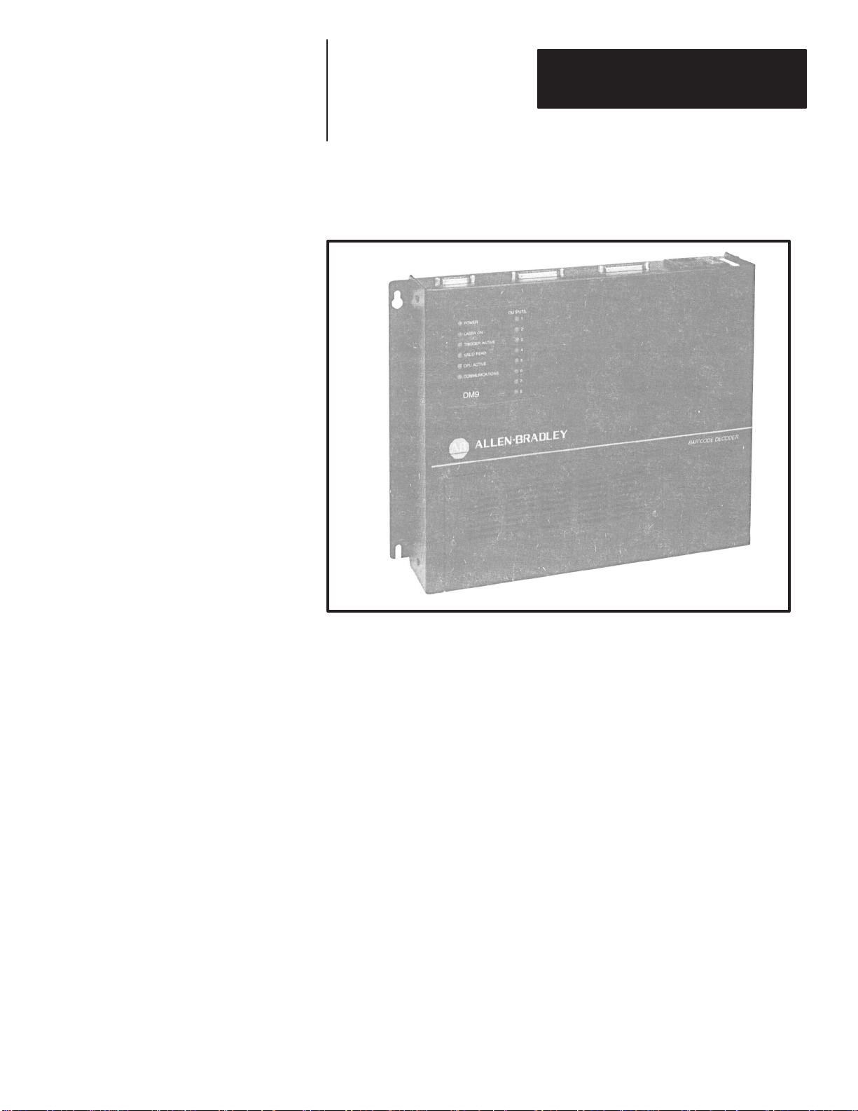
Figure 2.1
Catalog Number 2755-DM9, -DM9E
Chapter 2
Description of Hardware
Indicators
90-061-1
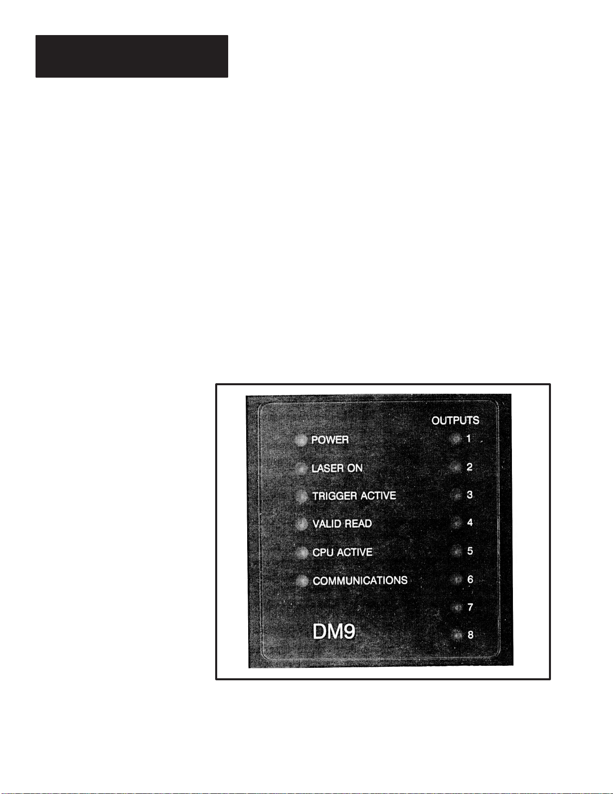
Fourteen LED indicators (Figure 2.2) provide an indication of the decoder
status. The indicators provide the following indications:
• POWER - This green indicator illuminates when power is applied to the
decoder.
• LASER ON - This red indicator illuminates when the decoder has enabled
the scan head to turn on the laser light source. The LED may illuminate
even if the scan head is disconnected or the “Laser On” switch for the
Catalog No. 2755-L7 or -L9 scan heads is in the OFF position.
• TRIGGER ACTIVE - This yellow indicator illuminates when the decoder
is in the triggered mode and scanning has been triggered by:
1. The package detector connected to the scan head.
2. A Start Scan command sent by the host.
3. The internal timer.
The LED remains on until a trigger OFF command is received.
• VALID READ - This green indicator illuminates momentarily whenever
the decoder has met the fields per scan and capture count parameters.
2–3
Page 14
Chapter 2
Description of Hardware
Note: This LED may not correspond to a read output condition (refer to page
4-41). In the triggered mode, the read output condition must meet the fields
per package parameter.
• CPU ACTIVE - This green indicator is continuously illuminated under
normal operation. Failure of the CPU ACTIVE indicator to illuminate is
an indication of a hardware failure.
• COMMUNICATIONS - This yellow indicator illuminates momentarily
whenever data is sent to or received at either of the communications ports.
• OUTPUTS 1 through 8- Each of these red indicators indicate the status
of the output modules. When an output module is turned on, the
respective indicator illuminates.
Note: If you have a Catalog No. 2755-DM9 decoder, the LED label is
attached. If you have a Catalog No. 2755-DM9E decoder, the LED label is
not attached. Apply the appropriate language label supplied with the
decoder.
Figure 2.2
LED Indicators
2–4
90-061-5
Page 15
Chapter 2
Description of Hardware
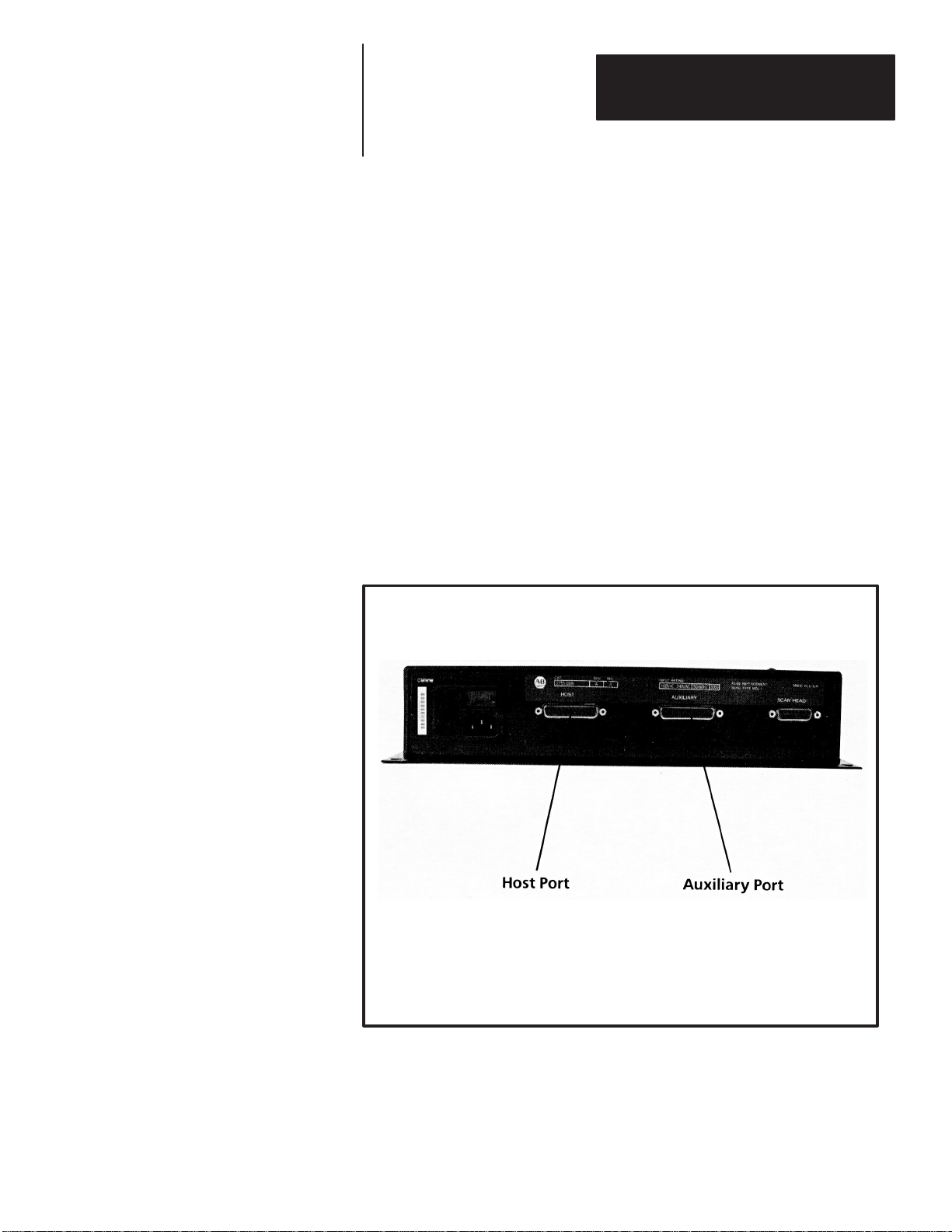
Communications Ports
There are two communication port connectors on the decoder:
• HOST port connector. The HOST port connector supports RS-232,
RS-422, and RS-485 communication interfaces. Through this port, you
can link the decoder to a host computer or programmable controller. Both
commands and data may be sent to/from the host device.
Note: The RS-485 interface allows the decoder to be installed as part of a
multi-drop network. Refer to Chapter 3 for a more detailed description.
• AUX port connector. The AUX or auxiliary port connector allows you to
program and monitor the decoder using one of the following CRTs:
Allen-Bradley Industrial Data Terminal (Catalog No. 1770-T1, -T2, and
-T3), Allen-Bradley T45 Laptop Terminal (Catalog No. 1784-T45),
Digital VT100, Televideo 955, Lear Siegler ADM 3E, or a
terminal/computer that emulates one of the terminals listed.
Figure 2.3
Communication Ports
90-061-2
2–5
Page 16
Chapter 2
Description of Hardware
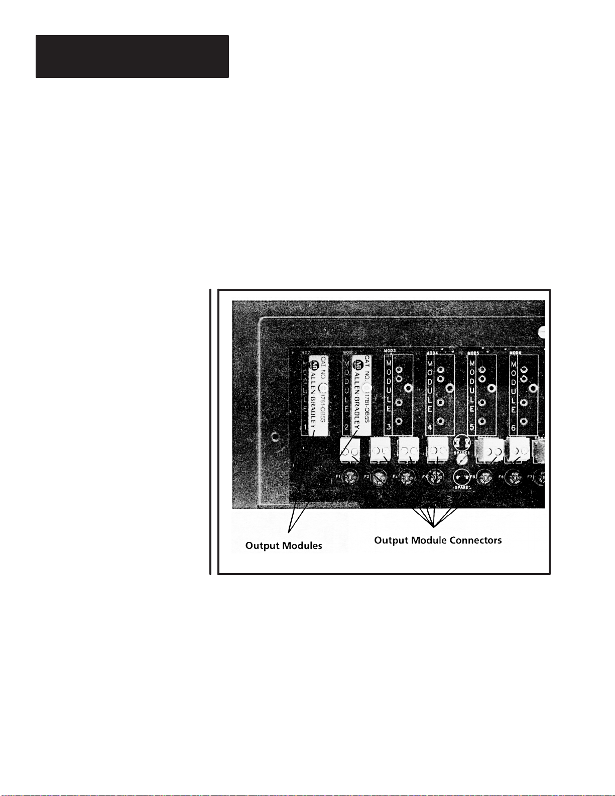
Output Modules
Two DC output modules (Catalog No. 1781-OB5S) are provided with the
decoder. You can add up to six more AC or DC output modules for a total of
eight. Module location #8 can also accept an input module for auto loading
match codes (refer to Chapters 3 and 4). All output module types can be
installed in any of the eight module slots. You can program the decoder to
turn on these output modules based upon the conditions you specify during
configuration of the decoder. Use these outputs to operate electromechanical
devices such as relays, alarms, etc. Fuses protect the decoder from power
overloads.
Figure 2.4
Output Modules
2–6
90-061-4
Page 17

Chapter 2
Description of Hardware
The following output modules are available.
Note: Output modules function as a switch, not as a power source.
Catalog No. 1781-0B5S 1781-0A5S 1781-OM5S
Nominal Line Voltage
-- 120 VAC 240 VAC
Maximum Line Voltage
Minimum Line Voltage 3.0 VDC 12 VAC 24 VAC
Maximum Peak Off State Voltage 60 VDC
Maximum Off-State Leakage
Static off-state dv/dt -- 200 V/ usec 200 V/ usec
Maximum On-State Current
Minimum On-State Current 10 mA DC 50 mA RMS 50 mA RMS
Maximum 1 Cycle Surge -- 4.0 A Peak 4.0 A Peak
Maximum 1 Second Surge
Peak On-State Voltage 1.5 V DC
60 VDC 140 VAC 280 VAC
400 V Peak 600 V Peak
1.0 mA 2.5 mA RMS 4.0 mA RMS
0.5 A DC 0.5 A RMS 0.5 A RMS
1.5 A DC -- --
1.6 V Peak 1.6 V Peak
The following input modules are available (for position No. 8 only). See
Chapters 3 and 4.
Note: The input modules require a voltage source for activation.
Catalog No. 1781-IB5S 1781-IA5S 1781-IM5S
Maximum Input Voltage 32 VDC 140V RMS/AC 280 V RMS/AC
Minimum Input Voltage
Input Resistance 1k ohm - Maximum Input Current 32mA DC @
Drop Out Current
Allowable Off State Input Current 1.0 mA DC 3.0 mA RMS 2.0 mA RMS
Allowable Off State Input V oltage
3.3 VDC 90V RMS/AC 180 V RMS/AC
10mA RMS @
32 VDC
1.0 mA DC 2.5 mA RMS 1.5 mA RMS
2.0 VDC 50 VRMS/AC 120 VRMS/AC
140 VRMS
8mA RMS @
280 VRMS
Note: Note polarity when connecting DC Input and Output modules.
2–7
Page 18
Chapter 2
Description of Hardware
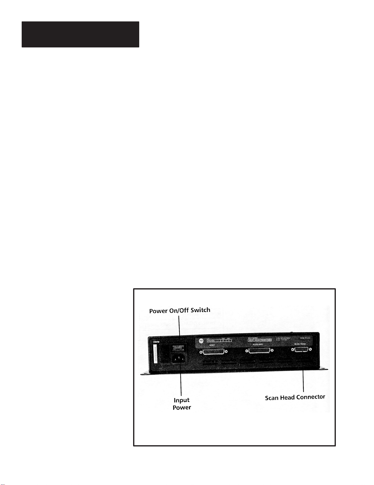
Power and Scan Head Connectors
The decoder will accept line voltages from 85 to 264 volts AC at a frequency
of 47 to 63 Hz without any adjustments. The Catalog No. 2755-DM9
decoder is supplied with a 120VAC rated power cord. If you are powering a
2755-DM9 decoder with a supply voltage greater than 120 VAC, you must
obtain a suitable power cord.
Note: Catalog No. 2755-DM9E is supplied with an unterminated power cord.
Attach a suitable connector using the diagram provided in Chapter 5.
A 15 pin D connector is provided on the decoder for connecting the laser
scan head. You can connect the decoder to the scan head using one of the
following:
• For Catalog No. 2755-L7 and -L9 scan heads use-
10 foot (3.05 meter) cable (Catalog No. 2755-CL10)
25 foot (7.62 meter) cable (Catalog No. 2755-CL25)
• For Catalog No. 2755-L4 and -L5 scan heads use-
10 foot (3.05 meter) cable (Catalog No. 2755-CK10)
25 foot (7.62 meter) cable (Catalog No. 2755-CK25)
Note: The scan head is powered by the decoder through the cable. The scan
heads do not require a separate power source.
Figure 2.5
Input Power and Scan Head Connectors
90-061-4
2–8
Page 19

Chapter 2
Description of Hardware
Accessories
The following table lists the accessories that you may require for use with the
decoder.
Catalog Number Item Description
Raster and side scanning devices that operate at 350 scans per
second. Raster scanners scan both vertical and horizontal directions
2755-L7①
2755-L9①
2755-L4F①
-L4R①
2755-L5R①
1781-OB5S DC Output Module 3 to 60 VDC output at 0.5 amperes.
1781-OA5S AC Output Module 12 to 140 VAC output at 0.5 amperes.
1781-OM5S AC Output Module 24 to 280 VAC output at 0.5 amperes.
1781-IB5S DC Input Module 3.3 to 32 VDC
1781-IA5S AC Input Module 90 to 140 VRMS/VDC
1781-IM5S AC Input Module 180 to 280 VRMS/VDC
2760-A485 RS-485 Connector Use these connectors to create cables for an RS-485 network.
2755-CL10 10-ft (3.05 meters) Scan Head Cable
2755-CL25 25-ft (7.62 meters) Scan Head Cable
2755-CK10 10-ft (3.05 meters) Scan Head Cable
2755-CK25 25-ft (7.62 meters) Scan Head Cable
W77104-899-01
Purchased
Locally
Package
Detector
Assembly
User Created Host Port Communications Cable For connecting host device to the decoder, refer to Chapter 6.
User Created Auxiliary Port Communications Cable
W77121-801-01
W77121-801-02
Industrial Medium Speed Bar Code
Scanner
Industrial High Speed Bar Code Scanner
Enhanced Medium Speed Scanner
Enhanced Medium Speed Raster Scanner
Replacement Fuse- Power Output
Modules
Replacement Fuse- Line Input Power 250V ( 1 amp, slow blow), 5 x 20 mm or 3AG
2755-NP3
2755-NP5
2755-NP1
2755-NP4
Power Cords -
120 V AC
220 V AC- Unterminated one end
simultaneously. Some of these scan heads have a maximum read
distance of 50” (1.27 meters) depending upon symbol size and
quality. Scanners can read Case Code symbols (symbols directly
printed on kraft paper/cardboard boxes).
Raster and side scanning devices that operate at 800 scans per
second. Raster scanners scan both vertical and horizontal directions
simultaneously. Some of these scan heads have a maximum read
distance of 30”
(76 cm) depending upon symbol size and quality .
Front or side scanners that operate at 200 scans per second. Some
of these scan heads have a maximum read distance of 50” (1.27
meter) depending upon symbol size and quality . Scanners can read
Case Code symbols (symbols directly printed on kraft
paper/cardboard boxes).
Raster scanners that operate at 200 scans per second. This scan
head has a maximum read distance of 45” (1.14 meters) depending
upon symbol size and quality . Scan head scans both vertical and
horizontal directions simultaneously. Scanner can read Case Code
symbols (symbols directly printed on kraft paper/cardboard boxes).
Use to connect decoder to Catalog No. 2755-L7 or -L9 scan head.①
Use to connect decoder to Catalog No. 2755-L7 or -L9 scan head.①
Use to connect decoder to Catalog No. 2755-L4 or -L5 scan head.①
Use to connect decoder to Catalog No. 2755-L4 or -L5 scan head.①
Plug-in type fuses provide overload protection for the decoder.
Optional, for 2755-L7, -L9 Scan Heads
Optional, for 2755-L7, -L9 Scan Heads
Optional, for 2755-L4, -L5 Scan Heads
Optional, for 2755-L4, -L5 Scan Heads
For connecting programming terminal to the decoder. Refer to
Appendix A.
Replacement power cord.
User must provide suitable connector.
① We have not provided the complete catalog number since these heads are available in a variety of configurations.
2–9
Page 20
Chapter
Chapter Objectives
How the Decoder Operates
A–B
3
How the Decoder Operates
This chapter provides a brief description of how the decoder operates. We
also provide a brief description of how the decoder communicates with host
devices.
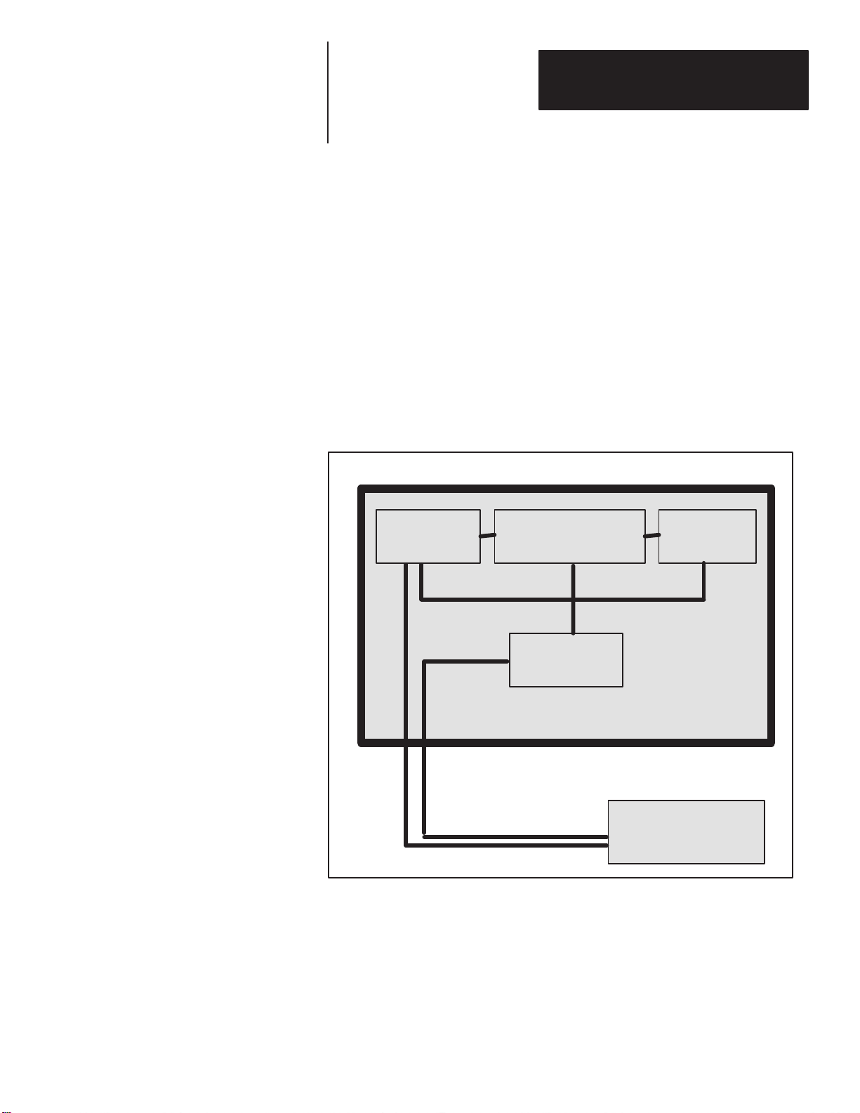
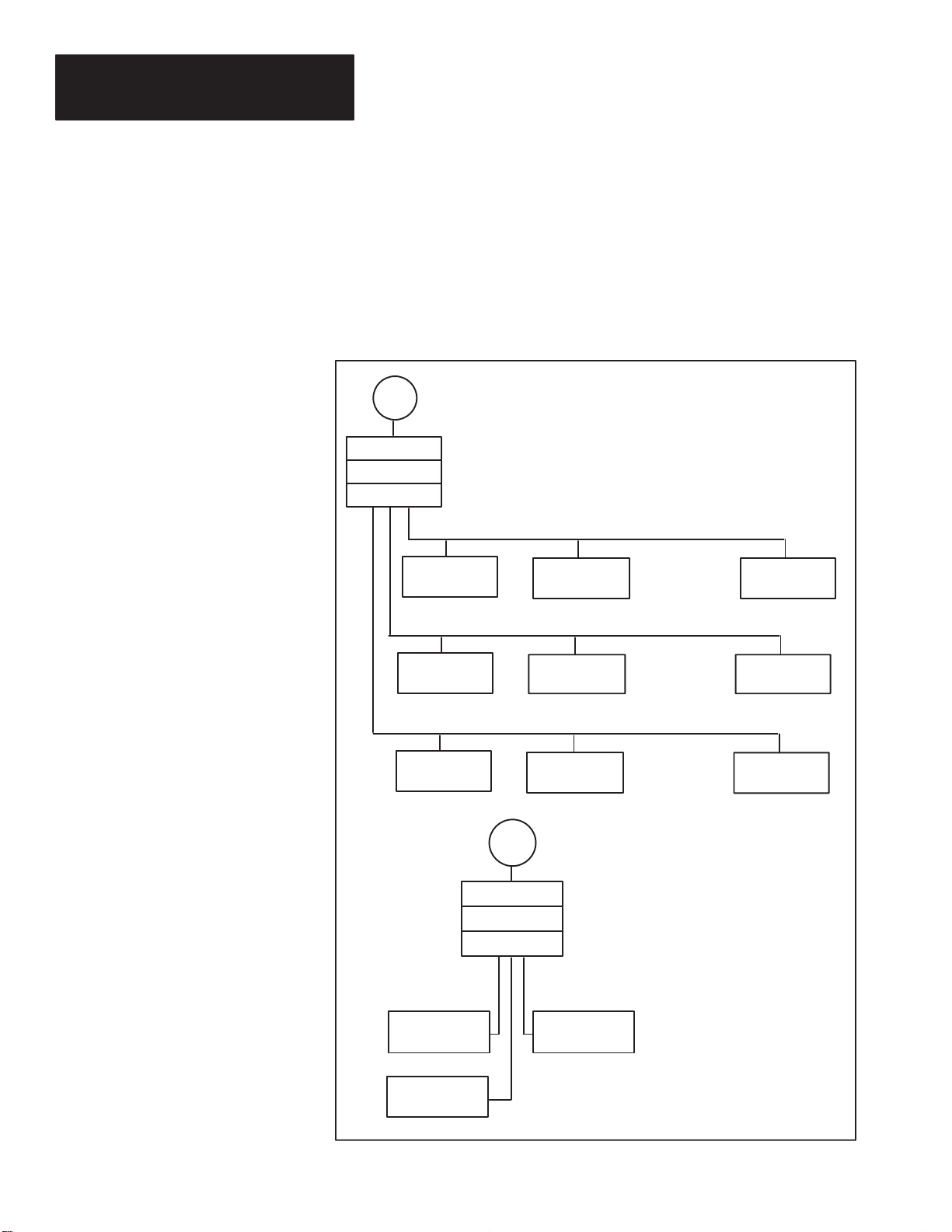
Figure 3.1 is a block diagram of the decoder.
Figure 3.1
Catalog Number 2755-DM9 Decoder
DECODER
DATA
ACQUISITION
POWER SUPPLY - An internal power supply provides power for both the
laser scan head and internal circuitry of the decoder. As stated earlier, the
source voltage may range from 85 to 264 volts AC. The power supply will
automatically adjust to the input voltage.
MICROPROCESSOR
POWER
SUPPLY
I/O
LASER SCAN HEAD
DATA ACQUISITION CIRCUIT - The data acquisition circuitry of the
decoder receives both video and synchronization signals from the laser scan
head. The data acquisition circuitry filters and stores blocks of data received
from the scan head in the Random Access Memory (RAM) of the decoder.
3–1
Page 21
Chapter 3
How the Decoder Operates
MICROPROCESSOR - The microprocessor reads the information obtained
by the data acquisition circuit, processes the information, and then makes
decisions on what to do with the decoded data based upon your programming
instructions.
I/O - A single 25 pin connector (HOST PORT) provides three different
interfaces (RS-232, RS-422, and RS-485) for communications with a host
computer or programmable controller. The I/O section of the decoder
supports asynchronous data transmission at baud rates of up to 38,400 bits
per second.
Another 25 pin connector (AUX PORT) provides an RS-232 interface for
programming and monitoring of the decoder using a programming terminal.
Refer to Chapter 2 for a listing of the terminals that can be used for
programming or monitoring.
Up to eight modules can be plugged into the circuit board of the decoder.
Refer to Chapter 2 for a description of the input and output modules that can
be used. Output modules function as switches, not as power sources (refer to
Figures 3.2 and 3.3).
Note: Outputs are initially turned off (open) when power is first applied to
the decoder and when the decoder is turned off.
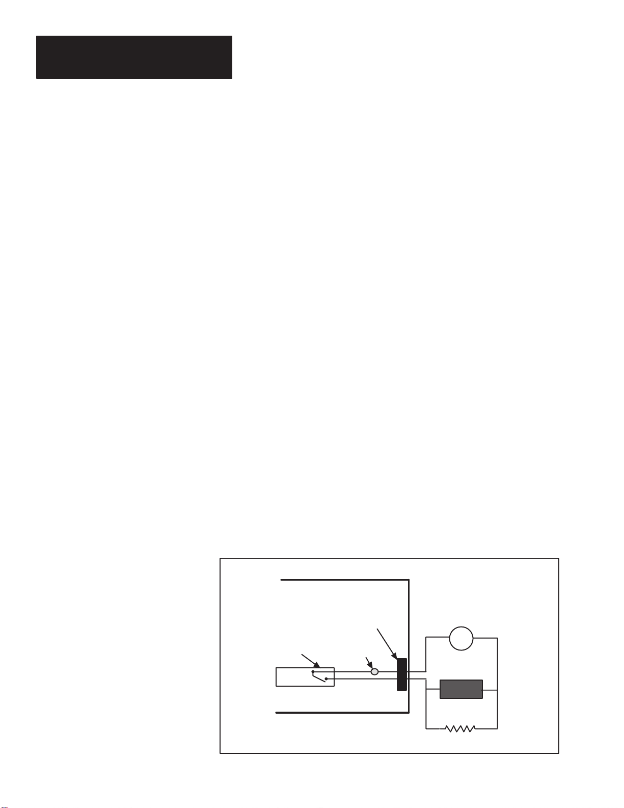
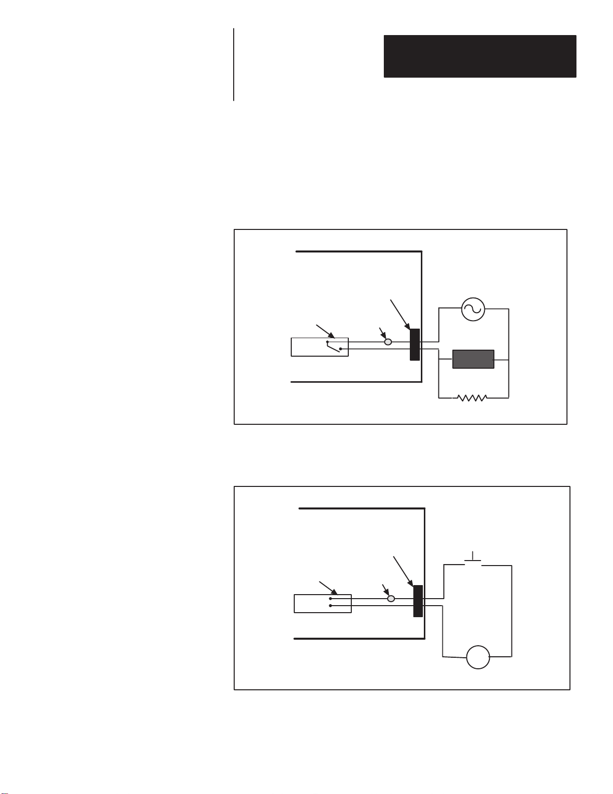
DC Output Module Application
Figure 3.2 illustrates a typical DC output module application. When using
high impedance loads, you may have to add an additional resistor (Rx) in
parallel with the load. Select a value for Rx that maintains a minimum
current of 10 mA through the output module in the on state. Typical values
for Rx range from 300 to 6,000 ohms depending upon the source voltage.
Figure 3.2
DC Output Module Application
DECODER
DC SOURCE 3-60 VDC
+
_
LOAD
_
+
DC OUTPUT MODULE
CONNECTOR BLOCK
FUSE
3–2
Rx
Page 22
Chapter 3
How the Decoder Operates
AC Output Module Application
Figure 3.3 illustrates a typical AC output module application. When using
high impedance loads, you may have to add an additional resistor (Rx) in
parallel with the load. Select a value for Rx that maintains a minimum
current of 50 mA RMS through the output module in the on state.
Figure 3.3
AC Output Module Application
DECODER
AC SOURCE
LOAD
Rx
AC OUTPUT MODULE
CONNECTOR BLOCK
FUSE
Input Module Auto Load Application
Figure 3.4 illustrates the auto load input module application.
Figure 3.4
Typical Input Module Auto Load Application
DECODER
Auto Load
CONNECTOR BLOCK
INPUT MODULE
AC or DC
MODULE LOCATION #8 ONLY
FUSE
Pushbutton
+
-
Communications
AC or DC SOURCE
As stated earlier the decoder can transmit decoded bar code information to a
host computer or programmable controller. The three communications
3–3
Page 23
Chapter 3
How the Decoder Operates
interfaces (RS-232, RS-422, and RS-485) provide a variety of ways to
accomplish communications with a host. Figure 3.5 illustrates some of the
possible host interfaces.
Note: You can also use the decoder as a stand-alone device using the discrete
outputs for control.
Figure 3.5
Communications Interface Examples
PLC
1771 I/O Rack
2760-RB
2760-SFC2
2755-DM9
2755-DM9
Decoder
2755-DM9
Decoder
Decoder
1
1
1
PLC TO DECODER USING
A FLEXIBLE INTERFACE
MODULE (RS-485)
2755-DM9
Decoder
2
2755-DM9
Decoder
2
2755-DM9
Decoder
2
PLC
PLC TO DECODER USING A
FLEXIBLE INTERFACE
MODULE (RS-232, RS-422)
• • • • • •
• • • • • •
• • • • • •
2755-DM9
Decoder
31
2755-DM9
Decoder
31
2755-DM9
Decoder
31
3–4
2755-DM9
Decoder
2755-DM9
Decoder
1771 I/O Rack
2760-RB
2760-SFC1
RS-232 or RS-422
2755-DM9
Decoder
Catalog No. 2760-RB is a Flexible Interface
Catalog No. 2760-SFC1, -SFC2 are Protocol Cartridges
Page 24
Chapter 3
How the Decoder Operates
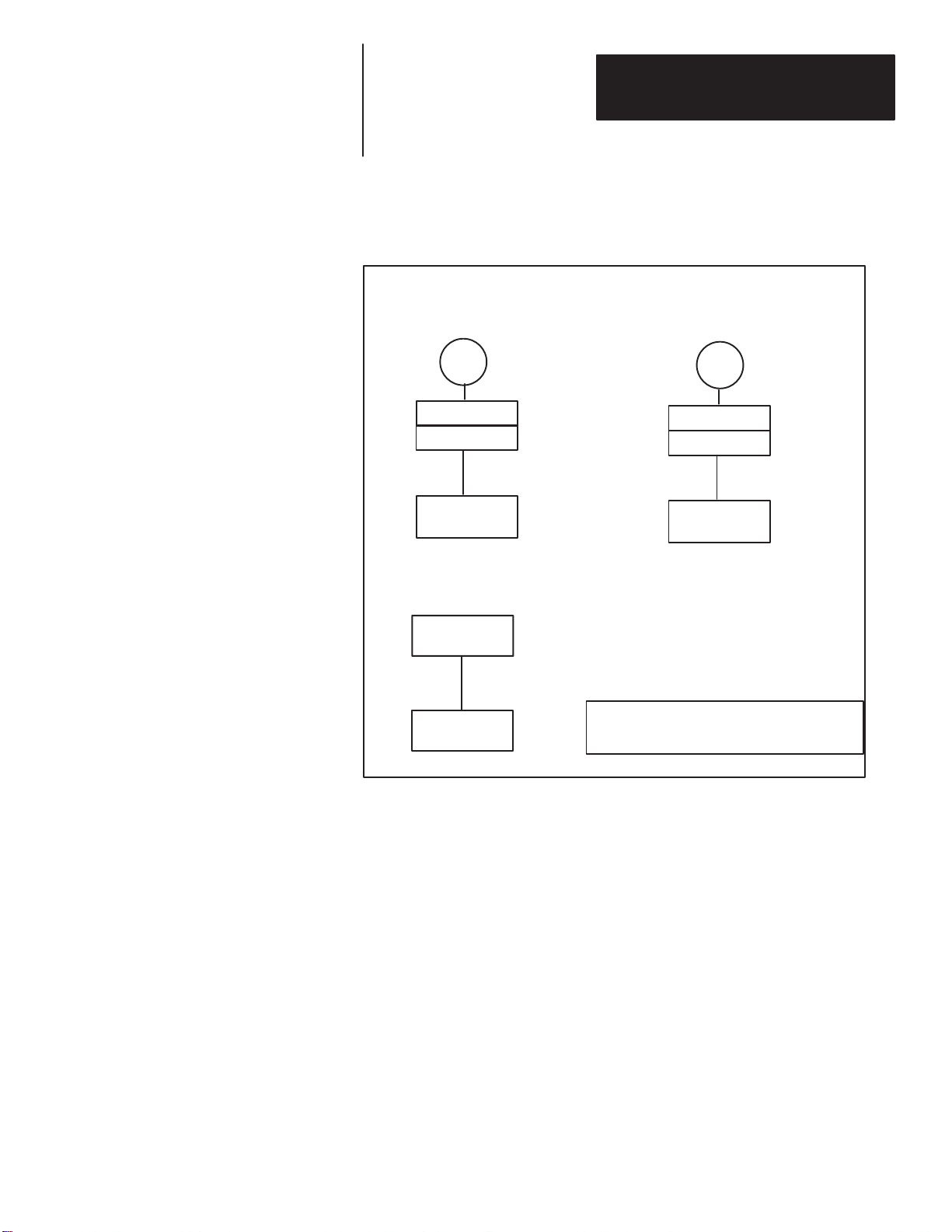
Figure 3.5
Communications Interface Examples (Continued)
PLC TO DECODER USING
AN ASCII MODULE
PLC
1771 I/O Rack
1771-DA
RS-232
2755-DM9
Decoder
COMPUTER TO
DECODER
Host Computer
RS-232 or RS-422
2755-DM9
Decoder
PLC TO DECODER USING A
BASIC MODULE
PLC
1771 I/O Rack
1771-DB
RS-232
2755-DM9
Decoder
Catalog No. 1771-DB is a BASIC I/O Module
Catalog No. 1771-DA is an ASCII I/O Module
ALLEN-BRADLEY LOCAL-AREA NETWORK - Using the Catalog No.
2760-RB Flexible Interface Module with the 2760-SFC2 protocol cartridge
and the DM9 in the RS-485 mode, you can multi-drop up to 31 devices on
each port of the 2760-RB module.
PROGRAMMABLE CONTROLLERS - You can connect the decoder to a
programmable logic controller in one of three ways:
• Through the Allen-Bradley Data Highway.
• Through a Flexible Interface Module (Catalog No. 2760-RB). This
module can be used to create an RS-485 Local Area Network or
point-to-point communications using the RS-232 or RS-422
communications interfaces.
• Directly, using a Catalog No. 1771-DB BASIC module or 1771-DA
ASCII I/O module.
HOST COMPUTERS- In most cases, you can directly connect your host
computer to the decoder using the RS-232 or RS-422 interface. The decoder
can also communicate with an industrial computer through the Allen-Bradley
Data Highway.
3–5
Page 25
Chapter 3
How the Decoder Operates
RAM and EEPROM Memory
Before you try to change the operating configuration of the decoder, you
should understand how configuration parameters are stored. The decoder has
two types of memory:
• EEPROM- Electrically Erasable Programmable Read Only Memory
contains the “non-volatile” operating configuration of the decoder. The
term “non-volatile” means that the memory is not lost when you turn the
power off or restart the decoder.
• RAM- Random Access Memory contains the current operating
configuration of the decoder. Any changes made to the the operating
configuration of the decoder are made to the decoder’s RAM. All
information stored in the RAM is erased when the power to the decoder is
turned off. When the decoder is turned back on (rebooted), the
configuration parameters are copied from non-volatile memory
(EEPROM) to the RAM.
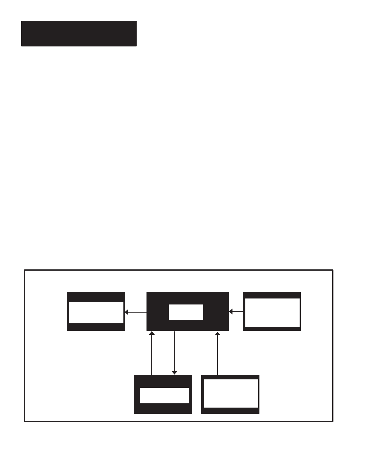
Figure 3.6 illustrates the relationship between the RAM and EEPROM
memory. Notice that the user interface is with the RAM memory. Also,
notice that the decoder transfers the contents of the RAM to the EEPROM
during a SAVE operation and copies the same contents from the EEPROM to
RAM during startup.
Note: The configuration in RAM determines the decoder performance
(operating characteristics).
Figure 3.6
Decoder Memory
3–6
Decoder
Performance
User Interface
RECALL
START-UP
RESTART
RAM
EEPROM
SAVE
DEFAULT
Default
Configuration
Settings
-Programmer
-Host
When you change the operating configuration of the decoder, you are
changing the configuration stored in the decoder’s RAM. Since the decoder
takes its current operating instructions from RAM, any changes you make
Page 26

Chapter 3
How the Decoder Operates
will become effective immediately (except for host communications
parameters listed below). If you want to enter changes into the decoder’s
permanent memory (EEPROM), you must use the SAVE command. When
the decoder is restarted, the operating parameters of the EEPROM are
transferred into RAM. If you don’t transfer the contents of the RAM to the
EEPROM (SAVE function), any changes made to the operating configuration
stored in RAM will be erased when the power is turned off.
Note: Unlike the other decoder operating parameters, changes to the
following parameters will not take effect until you SAVE the changes and
then restart the decoder.
• HOST PROTOCOL
• DEVICE ADDRESS
• ACK and NAK CHARACTERS①
Operating Modes
• BAUD RATE
• NUMBER OF DATA & STOP BITS
• PARITY
① Changes to ACK NAK characters will take effect immediately if you are in the ACK/NAK mode.
The decoder also stores the original factory set operating parameters in
EPROM. This type of memory cannot be changed by the user, and is always
available in case of a programming error. When you use a DEFAULT
command (described in next chapter), the decoder transfers the factory set
default parameters to the RAM. Once installed in RAM, the default
parameters control the operation of the decoder. If you want to save the
default parameters into the EEPROM, you must use the SAVE command.
A RECALL command (described in next chapter) transfers the previously
SAVED configuration from the EEPROM to the decoder’s RAM. Once
installed into RAM, the recalled configuration is displayed and controls
operation of the decoder.
When you configure the operation of the decoder, you will be required to
provide a variety of operating parameters. You should have an understanding
of the decoder’s operating modes prior to configuring the decoder (Chapter
4). The decoder operates in one of two modes:
• Continuous mode - In this mode, the decoder will continuously attempt to
decode data. Use this mode for initial scan head adjustments and
positioning.
• Triggered mode - In this mode, the decoder will only attempt to decode
data after receiving a trigger.
3–7
Page 27

Chapter 3
How the Decoder Operates
In the triggered mode of operation, there are three possible trigger sources:
• Host command - The command is generated by a host computer or
programmable controller.
• Package detect - A package detector connected to the scan head is the
source for the trigger.
• Internal timer - The internal timer cycles the trigger from on to off based
on a timed interval.
Trigger Ending Coditions
Response Modes
When a trigger on is received, the decoder will continuously attempt to
decode bar codes until one of the following trigger ending conditions occurs:
(a) The number of fields (bar codes) per package count is satisfied.
(b) A trigger off command is sent by a host device.
(c) Package detect signal is no longer present.
(d) The internal timer (No-Read timer) times out.
In the triggered mode of operation there are two options which determine
when the decoder will send bar code information to a host and/or operate
discrete outputs:
• After Valid Package - A valid package is a package that has valid bar
code symbols and meets the fields (bar codes) per package count
(condition
(a) listed above).
• End of Trigger - Refer to trigger ending conditions (b, c, d) listed above.
3–8
Page 28

Chapter
Chapter Objectives
Initial Programming of the Decoder
A–B
4
Configuring Your Decoder
Because the decoder can be used many ways, you will need to configure the
decoder to meet the requirements of your application. To do this, you must
make some decisions. We will show you how to use the menus and setup
screens that appear on a programming terminal to select the options you
need.
You must configure the decoder to meet the requirements of the application.
You can configure the decoder either before or after installation. If you
change the configuration while a triggered decode is in progress, there is
the possibility of missing a package and/or losing data.
Note: The default parameters for the decoder are given in Appendix B. If
these settings meet your requirements, you will not have to program the
decoder.
You will need the following equipment:
1. Decoder with power cable.
2. One of the following programming terminals:
• Allen-Bradley Industrial Terminal (Catalog No.1770-T1, -T2, or -T3).
• Allen-Bradley T45 Laptop Terminal (Catalog No. 1784-T45).
• Lear Siegler 3E.
• Televideo 955.
• DEC VT-100.
• A terminal or personal computer that accurately emulates one of the
above.
3. A cable to connect your programming terminal to the decoder.
Note: Prior to configuring your decoder, we suggest that you review the
description of how the decoder stores configuration data (refer to Chapter 3,
RAM and EEPROM Memory descriptions).
Note: Refer to Appendix A for programming terminal setup. The
programming terminal you use must be configured with the following
parameters:
Number of data bits: 8
Number of stop bits: 1
Baud rate: 9600
Parity: None
Flow Control: XON / XOFF
4–1
Page 29

Chapter 4
Configuring Y our Decoder
Programming Terminal Cable
Menus and Setup Screens
Programming of the decoder is done through the AUX connector on the back
of the decoder.
female, D type connector. Depending upon your programming terminal,
most standard RS-232 communications cables will work. If you need to
create a communications cable, refer to Appendix A.
You can program and/or monitor the operation of the decoder using the
following CRT screens:
The AUX port connector on the decoder is a standard 25 pin,
• Select Language Screen - Use this screen to select English, French,
German, Italian, or Spanish language screens.
• CRT Select Menu - You use this menu to select the type of programming
terminal being used.
• Select operation Menu - Using this menu, you select one of six
operations:
1) Display Labels Screen- Displays bar code labels as they are decoded.
2) System Status Screen- Displays the status of the decoder.
3) Setup Screens Setup Screen 1- Use this screen to configure the host interface which
includes host message format, host communications parameters and
protocol, and filtering of the package detect input.
Start-up Procedure
4–2
Setup Screen 2- Use this screen to configure the decoder for the bar
code symbologies, bar code lengths, scan head operation, match code
settings, and configuration of output modules.
4) Reset Status and Counters
5) Restart System
6) Select Language Screen- This screen allows you to reselect one of the
following languages:
• English
• French
• German
• Italian
• Spanish
After you have connected the programming terminal to the decoder and
attached the power cord:
Step 1 - Turn ON the programming terminal and configure the terminal for
communications with the decoder. Appendix A provides information on
setting up the programming terminal.
Page 30

Chapter 4
Configuring Y our Decoder
Step 2 - Turn the decoder ON. The green LEDs, labeled POWER ON and
CPU ACTIVE, will light.
Step 3 - When the following screen appears, press the key that corresponds
to the language you are using. All of the remaining screens will appear in the
selected language.
SELECT LANGUAGE CHOIX DU LANGAGE WAEHLE SPRACHE
1) English 1) Anglais 1) Englisch
2) French 2) Francais 2) Franzoesisch
3) German 3) Allemand 3) Deutsch
4) Italian 4) Italien 4) Italienisch
5) Spanish 5) Espagnol 5) Spanisch
Press 1, 2, 3, 4, 5, or ESC Appuyer 1, 2, 3, 4, 5 ou ESC Drueck
e 1, 2, 3, 4, 5, oder ESC
SELEZIONARE LINGUA SELECCIONAR LENGUA
1) Inglese 1) Ingles
2) Francese 2) Frances
3) Tedesco 3) Aleman
4) Italiano 4) Italiano
5) Spangnolo 5) Castellano
Premere 1, 2, 3, 4, 5 o ESC Pulsar 1, 2, 3, 4, 5, o ESC
Step 4 - After selecting the language, the decoder will display the CRT select
screen. Press the key (1, 2, 3, 4, or 5) that corresponds to the terminal you
are using. Pressing the [ESC] key, will return you to the language selection
screen.
2755-DM9 Bar Code Reader VX.XX
Copyright 1990 Allen-Bradley Company, Inc.
SELECT CRT TYPE
1 - Allen-Bradley 1770 Industrial Terminal
2 - Allen-Bradley T45 Portable Terminal
3 - Lear Siegler ADM 3E
4 - Televideo 955
5 - Digital VT100
Press 1, 2, 3, 4, 5 or ESC
Step 5 - After selecting the CRT type, the decoder will display the select
operation menu. The remaining displays that you will see depends upon the
operation that you select.
4–3
Page 31

Chapter 4
Configuring Y our Decoder
Select Operation Menu
After selecting the CRT type, the following Select Operation menu will
appear:
2755-DM9 Bar Code Reader VX.XX
Copyright 1990 Allen-Bradley Company, Inc.
SELECT OPERATION
1) Display Bar Code Labels
2) Display Status and Counters
3) Display/Change Configuration
4) Reset Status and Counters
5) Restart
6) Select Language
Press 1, 2, 3, 4, 5, 6, or ESC
The following are explanations of each operation listed on the Select
Operation menu:
1) Display Bar Code Labels - This operating mode allows you to monitor
bar code labels as they are being scanned. After selecting this operation by
pressing the [1] key, bar code labels will be displayed as they are decoded.
The display will scroll up as new labels appear on the bottom of the screen.
If more than one label is decoded on the same scan, the labels will be
displayed on the same line separated by a space. If a no-read condition
occurs, the decoder will display the no-read message that you enter as part of
the decoder configuration. Pressing the [ESC] key will exit this function.
The following is an example of how the display bar code labels screen might
appear:
4–4
Page 32

(Continued)
Chapter 4
Configuring Y our Decoder
19876367 3456721
59874292
45763019
56474821
10945280
45674895 7689577
87599039
35426881
11987454
54664778
87997070
56400982
54664747
09585746 7563778
53647747
87745646
35647465
6545456
2) Display Status and Counters - After selecting this operation by pressing
the [2] key at the select operations menu, the decoder will display the
following:
• Decoder Performance - The percentage of decodable scans over a 100
scan sample. The 100 scan sample is not made up of the raw scans from
the scan head. Instead, the 100 scan sample is made up of scans which
have passed through a “qualifier” circuit in the data acquisition circuitry.
The “qualifier” circuit acts as a pre-filter that discards empty, partial, or
noisy scans before decoding is attempted. Because of this, it is possible
to have a high decoder performance even though only a small percentage
of the scans are crossing the label (such as when a raster scan head is used
or the label is moving). This display is only available if continuous
trigger mode is selected and fields per package parameter (entered as part
of configuration programming) is anything but “any”.
Note: You can use the decoder performance monitor during:
Installation. By monitoring the percentage of good reads, you will be able to
determine the optimum location for the scan head in relation to the label(s)
being read.
Operation. If the percentage of good reads drops significantly below what it
was during installation, the scan head window may require cleaning or the
label quality may have degraded.
• No-Read Counter - The number of No-Reads. This counter is
incremented each time a package start trigger is generated and a stop
trigger occurs without a valid package. No-reads also occur when the
decoder does not decode the correct number of fields on a package as
4–5
Page 33

Chapter 4
Configuring Y our Decoder
specified by the fields per package configuration parameter. Data that is
lost due to an overflow of the buffer does not increment this counter.
• Package Counter- The number of packages detected. This counter is
incremented each time a package trigger is generated by the scan head
package detector, a host command, or the internal timer.
• Output Counters 1 through 8 - The number of times an output condition
has occurred.
The following is an example of how the display status and counters screen
may appear:
2755-DM9 Bar Code Reader VX.XX
Copyright 1990 Allen-Bradley Company, Inc.
Decoder Performance : 100%
No-Read Counter : 10
Package Counter : 300
Output Counter 1 : 44
Output Counter 2 : 45
Output Counter 3 : 56
Output Counter 4 : 5
Output Counter 5 : 33
Output Counter 6 : 23
Output Counter 7 : 40
Output Counter 8 : 67
ESC to Exit
This screen is updated approximately once per second.
Press the [ESC] key to exit the function.
3) Display/Change Configuration- Pressing the [3] key at the operation
menu will allow you to change the operating configuration of the decoder.
Two setup screens are used to configure the decoder. Before entering the
setup screens, the decoder will display a message asking you if you want the
outputs disabled during configuration:
4–6
Page 34

Chapter 4
Configuring Y our Decoder
CAUTION
Configuration changes may cause the discrete outputs to switch.
If outputs are to remain ENABLED, press ESC.
Otherwise press any other key to continue. Outputs
will be DISABLED until the device is restarted.
Note: We recommend that you disable the outputs while configuring the
decoder. This will prevent the outputs from being turned on unintentionally
during changes to the configuration.
If you press any key other than the [ESC] key, the outputs will be disabled
(off) during configuration. The outputs will remain disabled until you restart
(refer to restart operation) or cycle the power off and then back on
(remember to SAVE configuration first). If you press the [ESC] key, the
outputs will remain enabled during configuration. After responding to the
above message, the decoder will display the first of two setup screens:
------- MESSAGE FORMAT ------- ------- HOST COMM -------
_______________________________________
Commands: ESC Change: SPACE Cursor Control: ARROWS
_______________________________________
SEND BAR CODE DATA: Yes BAUD RATE: 9600
SEND PACKAGE COUNT: No BITS/CHAR: 8 Data, 1 Stop
SEND BAR CODE TYPE: No PARITY: None
SEND SOURCE IDENTIFIER: No
SEND HEADER MESSAGE: No ACK CHAR: None
SEND NO-READ MESSAGE: No NAK CHAR: None
START SCAN CHAR: None
EXPAND UPC-E: Yes STOP SCAN CHAR: None
SOURCE IDENTIFIER: LARGE BUFFER: No
LABEL DELIMITER: None RESPONSE MODE: End of Trigger
START CHAR: None HOST PROTOCOL: RS232
END MESSAGE: CRLF DEVICE ADDRESS: 01
TRANSMISSION CHECK: None
HEADER MESSAGE:
NO-READ MESSAGE:
CODE 39 CHECK CHAR: No SEND: No ---PACKAGE DETECT INPUT---
I 2-OF-5 CHECK CHAR: No SEND: No FILTER: No
CODABAR CHECK CHAR: No SEND: No SENSE: LO = Package
If you press the [ESC] key to select the command bar, you will notice that
the NEXT PAGE command is highlighted in reverse video on the bottom of
the screen. Press the [RETURN] key to enter the command. The decoder
will then display the second setup screen, which looks like this:
4–7
Page 35

Chapter 4
Configuring Y our Decoder
-- SYMBOLOGY -- -------- LENGTHS -------- -------- SCANNER CONTROL -------CODE 39: Yes 00 00 00 00 00 00 00 00 LASER-ON MODE: Continuous
I 2-OF-5: No 00 00 00 00 00 00 00 00 DECODE TRIGGER: Package Detect
CODE 128: No 00 00 00 00 00 00 00 00 CAPTURE COUNT: 2 (scans)
CODABAR: No 00 00 00 00 00 00 00 00 FIELDS/SCAN: 1
UPC-A: No FIELDS/PACKAGE: 1
UPC-E: No NO-READ TIMER: 0000 (msec)
EAN-8: No INTER-SCAN TIMER: 0000 (msec)
EAN-13: No MATCH COMPLETE: 1
---------MATCH CODE TABLE-------------- ----------- OUTPUTS [DISABLED]--------
1) CODE 39 N None 0000
2) CODE 39 N None 0000
3) CODE 39 N None 0000
4) CODE 39 N None 0000
5) CODE 39 N None 0000
6) CODE 39 N None 0000
7) CODE 39 N None 0000
8) CODE 39 N None 0000
_______________________________________
Commands: ESC Change: SPACE Cursor Control: ARROWS
_______________________________________
Note: The two setup screens display the current operating parameters of the
decoder. Any changes made to the configuration will become effective
immediately with the exception of the host communication parameters. In
order for changes to the host port baud rate, stop bits, parity, host protocol, or
device address to take effect, you must save the changes to the decoder’s
EEPROM (SAVE command) and then restart. You can restart the decoder by
pressing the [5] key (Restart System) at the Select Operation menu, through a
host command, or by turning the power off and then back on.
In the following sections of this chapter we will provide a description of all
the options available on the two setup screens. We will also provide a
step-by-step programming example.
4) Reset Status and Counters- Pressing the [4] key at the operations menu
will reset the package counter, no-read counter, and output counters. Prior to
resetting the counters, the decoder will display a confirmation prompt:
RESET STATUS AND COUNTERS . . . Confirm (Y/N)
Press the [Y] key to confirm the reset. Pressing the [N] key will cancel the
reset function.
4–8
5) Restart System- Pressing the [5] key at the select operation menu will
reboot the decoder. This has the same effect as turning the power off and
then back on. Prior to restarting the system, the decoder will display a
confirmation prompt:
Page 36

Chapter 4
Configuring Y our Decoder
RESTART SYSTEM . . . Confirm (Y/N)
Press the [Y] key to confirm the restart. Pressing the [N] key will cancel the
restart function.
6) Select Language- Pressing the [6] key at the operations select menu will
display the following menu:
SELECT LANGUAGE CHOIX DU LANGAGE WAEHLE SPRACHE
1) English 1) Anglais 1) Englisch
2) French 2) Francais 2) Franzoesisch
3) German 3) Allemand 3) Deutsch
4) Italian 4) Italien 4) Italienisch
5) Spanish 5) Espagnol 5) Spanisch
Using and Editing the Configuration (Setup) Screens
Press 1, 2, 3, 4, 5, or ESC Appuyer 1, 2, 3, 4, 5 ou ESC Drueck
e 1, 2, 3, 4, 5, oder ESC
SELEZIONARE LINGUA SELECCIONAR LENGUA
1) Inglese 1) Ingles
2) Francese 2) Frances
3) Tedesco 3) Aleman
4) Italiano 4) Italiano
5) Spangnolo 5) Castellano
Premere 1, 2, 3, 4, 5 o ESC Pulsar 1, 2, 3, 4, 5, o ESC
Press the key that corresponds with the language you want to use. After
selecting the language, the decoder will return you to the CRT selection
screen. All of the other screens will appear in the selected language.
When programming the decoder, use the two configuration (setup) screens to
set operating parameters. There are two types of fields that you can change
on the configuration screens:
• SELECT Fields - In the select fields, you have fixed selections such as
YES or NO. Pressing the [SPACE] bar multiple times will step through
the selections available. Pressing the [RETURN] key will enter the
selection.
• EDIT Fields - In the edit fields, you can enter strings of ASCII character
codes, numeric values, or text. Pressing the [SPACE] bar will open the
field for changes and clear the current values. You can then enter new
data. Pressing the [RETURN] key will close the field and enter the data
Pressing the [ESC] key will cancel any changes, return the values back to
the original contents when the field was opened, and close the field.
4–9
.
Page 37

Chapter 4
Configuring Y our Decoder
To do this: You must: Comments
Depending upon the type of field (select or edit) that you are configuring, use
the commands listed in Table 4.A:
Return to SELECT OPERA TION
menu.
Change any field. Press [SPACE] bar.
Enter a new or different value. Press [RETURN] key.
Move to a different field.
Move to next menu.
Transfer new parameters into the
Decoder’s memory (EEPROM).
Recall previously set parameters
from the Decoder’s memory
(EEPROM–User Definable).
Reset decoder to factory set
parameters (EPROM–Defaults).
SAVE
RECALL
DEFAULT
Press the [ESC] key to select the
command bar and then press the [ESC]
key again.
Press [RETURN] key or arrow keys.① See note ① below.
Press [ESC] key to select the command
bar and press the [RETURN] key.
Press [ESC] key to select command bar.
Use [SPACE] bar to select SA VE and
press the [RETURN] key. Press [Y] key
at confirmation prompt.
Press [ESC] key to select command bar.
Use [SPACE] bar to select RECALL and
press the [RETURN] key. Press [Y] key
at confirmation prompt.
Press [ESC] key to select command bar.
Use [SPACE] bar to select DEFAULT
and press the [RETURN] key. Press [Y]
key at confirmation prompt.
In select fields, next option is
displayed.
In edit fields, field is cleared and new
data can be entered.
New value is highlighted in reverse
video.
New configuration parameters are
transferred to the decoder’s
EEPROM.
Previously set parameters are
displayed.
Refer to Appendix B for factory set
parameters.
① Allen-Bradley Industrial Terminals (Catalog Number 1770-T1, -T2, or -T3) do not have arrow keys. Use the [CTRL] and U, D, L or R keys for Up, Down, Left or Right cursor
movement.
EDIT FIELDS - There are three types of data that can be entered or
modified in an edit field:
1) ASCII character codes-(decimal values 0 to 255)
2) Numeric values
3) Text strings
To open an edit field for a change, press the [SPACE] key. The cleared field
will appear as a block in reverse video and the decoder will display the edit
keys you can use at the bottom of the screen. All other keys will be ignored:
EDIT -- Cancel:ESC Enter:RETURN Erase Char: BACKSPACE
4–10
Page 38

Chapter 4
Configuring Y our Decoder
Type in the new data and press the [RETURN] key to close the field and
enter the data.
Note: Pressing the [ESC] key while you are entering data in an edit field will
return the contents of the field back to the original contents prior to editing.
When you enter a value in a field that requires an ASCII decimal value, you
have three options:
1) You can enter the decimal (numeric) equivalent value (refer to Appendix
C). After entering the decimal value, the selected ASCII character will be
displayed.
2) You can enter the ASCII character (non-numeric only) such as “T”. The
decoder will automatically enter the decimal equivalent value (T = 84).
3) If you press the [RETURN] key when the field is empty, “NONE” is
displayed (no ASCII value is defined). A decimal value of 255 is also
interpreted as “NONE”.
You can enter non-printable ASCII control characters into the following edit
fields:
• Source Identification Message
• Header Message
• No-Read Message
• Match Table Entry
To enter non-printable ASCII control characters (ASCII 0 through 31) into a
text string, refer to Table 4.B. For example: to enter carriage return and line
feed control characters, you would enter %M%J. The decoder will interpret
%M%J as the ASCII control characters CR and LF. The % character is
equivalent to ASCII 37 (decimal). Non-printable control characters are
always entered as a two character sequence and the second character must be
listed in Table 4.B. To enter the character %, you must use %%.
Note: Some fields have restrictions on the type of data that you can enter.
For example: numeric values only are allowed in the inter-scan timer field.
If you attempt to enter an invalid character, you will hear a beep. Numeric
values are also checked for range (min and max values) when the [RETURN]
key is pressed. An audible beep indicates a value is out of the specified
range. To correct an entry, you can either:
• Delete the incorrect entry by using the backspace, left arrow, [CTRL] [L],
or rubout keys.
• Press the [ESC] key once to return the field back to its original contents.
4–11
Page 39

Chapter 4
Configuring Y our Decoder
ASCII Control
Character
NUL %@ VT %K SYN %V
SOH %A FF %L ETB %W
STX %B CR %M CAN %X
ETX %C SO %N EM %Y
EOT %D SI %O SUB %Z
ENQ %E DLE %P ESC %[
ACK %F DC1 %Q FS %\
BEL %G DC2 %R GS %]
BS %H DC3 %S
HT %I DC4 %T US %
LF %J NAK %U
Enter:
ASCII Control
Character
Enter:
ASCII Control
Character
RS
SELECT FIELDS- To change the contents of a select field, press the
[SPACE] key. After pressing the [SPACE] key, he next option is displayed
and the decoder will display the control keys you can use at the bottom of the
screen. All other keys are ignored:
SELECT -- Cancel:ESC Change:SPACE Enter:RETURN
Enter:
∧
%
_
Command Bar
4–12
Press the [SPACE] key again until the option you want is displayed. Press
the [RETURN] key to enter the selected option.
When you first enter either setup screen you will observe the following at the
bottom of the display:
Change:SP ACE Cursor Control: ARROWSCommands : ESC
Notice that the command bar display provides a quick reference to the
commands used to edit the setup screen. If you select the command bar by
pressing the [ESC] key, the following will be displayed:
COMMAND - - Exit: ESC Select: RETURN Next Command: SPACE
NEXT PAGE
THIS PAGE RECALL SAVE DEFAULT
After selecting the command bar, you will notice that the first command
option NEXT PAGE is highlighted in reverse video. To display the other
Page 40

Chapter 4
Configuring Y our Decoder
(next) setup screen you would press the [RETURN] key. To select another of
the displayed commands, press the [SPACE] key until the desired command
is highlighted and then press the [RETURN] key. Pressing the [ESC] key
after selecting the command bar will return you to the select operation menu.
The following are explanations of each command in the command bar:
• NEXT PAGE - Selecting this command will display the other setup
screen. Remember that there are two setup screens used to configure the
decoder.
• THIS PAGE - Selecting this command will return you to the top of the
current setup screen.
• RECALL - Selecting this command will recall all the previously SAVED
configuration parameters from the decoder’s Electrically Erasable
Programmable Read Only Memory (EEPROM) to the decoder’s Random
Access Memory (RAM). Once moved into the decoder’s RAM, the
recalled configuration is displayed and controls the operation of the
decoder.
• SAVE - Selecting this command will save all the configuration parameters
to the decoder’s EEPROM. You must use the save function after
programming, or the decoder’s operating configuration will revert back to
the original configuration after a restart (or power loss) of the decoder.
• DEFAULT - Selecting this command will change the setup to the factory
default selections. Refer to Appendix B for the default parameters. If the
default values meet the requirements of your application, you do not have
to program the decoder.
4–13
Page 41

Chapter 4
Configuring Y our Decoder
Setup Screen #1
Figure 4.1 shows the first setup screen. The first setup screen configures the
communication parameters and host protocol. We have used lowercase
letters to indicate fields of the configuration data. These letters are keyed to
Table 4.C, listing the options available for each field type. Following the
table is a short description of the effect each option has on the decoder
operation.
Figure 4.1
Setup Screen #1
----------- MESSAGE FORMAT ----------- ----------- HOST COMM -----------
SEND BAR CODE DATA: a BAUD RATE: u
SEND PACKAGE COUNT: b BITS/CHAR: v
SEND BAR CODE TYPE: c PARITY: w
SEND SOURCE IDENTIFIER: d
SEND HEADER MESSAGE: e ACK CHAR: x
SEND NO-READ MESSAGE: f NAK CHAR: y
START SCAN CHAR: z
EXPAND UPC-E: g STOP SCAN CHAR: aa
SOURCE IDENTIFIER: h LARGE BUFFER: bb
LABEL DELIMITER: i RESPONSE MODE: cc
START CHAR: j HOST PROTOCOL: dd
END MESSAGE: k DEVICE ADDRESS: ee
TRANSMISSION CHECK: l
HEADER MESSAGE: m
NO-READ MESSAGE: n
CODE 39 CHECK CHAR: o SEND: p ---PACKAGE DETECT INPUT---
I 2-OF-5 CHECK CHAR:
CODABAR CHECK CHAR: s SEND: t SENSE: gg
q SEND: r FILTER: ff
4–14
Commands: ESC Change: SPACE Cursor Control: ARROWS
Page 42

Chapter 4
Configuring Y our Decoder
Reference
Letter
a
b
c
d
e
f
g
h
i
j
k
Description
Send bar code field data to host.
Send package count to host.
Send bar code type indicator to host.
Send source identification string to host.
Send header message to host. Select Yes or No N/A
Send no–read message to host, if
no–read.
Expand UPC–E bar codes. Select Yes or No N/A
Source identification message. Edit N/A Up to four ASCII
Label delimiter character. Edit N/A Numeric ASCII code ( 0 to
Start character. Edit N/A Numeric ASCII code ( 0 to
End of message. Select None, CRLF, CR, LF,
Field
T ype
Select Yes or No N/A
Select Yes or No N/A
Select Yes or No N/A
Select Yes or No N/A
Select Yes or No N/A
Options (Select Field
Only)
ETX
Valid Entries (Edit Field
Only)
characters.①
255) 255 = None. Refer
to Appendix C.
255) 255 = None. Refer
to Appendix C.
N/A
l
m
n
o
p
q
r
s
t
① You can enter non-printable characters in these fields, refer to the table on page 4-12.
Transmission check method. Select None, LRC,
Header message. Edit N/A Up to 32 ASCII
No–read message. Edit N/A Up to 32 ASCII
Employ check character for Code 39. Select Yes or No N/A
Send Code 39 check character. Select Yes or No N/A
Employ check character for Interleaved
2–of–5.
Send Interleaved 2–of–5 check
character.
Employ check character for Codabar. Select Yes or No N/A
Send Codabar check character. Select Yes or No N/A
N/A
Checksum–LSB,
Checksum–MSB
characters.①
characters.①
Select Yes or No N/A
Select Yes or No N/A
4–15
Page 43

Chapter 4
Configuring Y our Decoder
Reference
Letter
u
v
w
x
y
z
aa
bb
cc
Description
Host port–baud rate. Select 300, 1200, 2400, 4800,
Host port–number of data and stop bits. Select
Host port–parity. Select None, Odd, or Even N/A
Host port–ACK character. Edit N/A Numeric ASCII code ( 0 to
Host Port–NAK character. Edit N/A Numeric ASCII code ( 0 to
Host port–start scan character. Edit N/A Numeric ASCII code ( 0 to
Host port–stop scan character. Edit N/A Numeric ASCII code ( 0 to
Enable host port buffer (8k bytes). Select Yes or No N/A
Response mode. Select
Field
T ype
Options (Select Field
Only)
9600, 19200, 38400
8 data, 1 stop
8 data, 2 stop
7 data, 1 stop
7 data, 2 stop
End of Trigger, or After
V alid Package.
Valid Entries (Edit Field
Only)
N/A
N/A
255) 255 = None.②
255) 255 = None.②
255) 255 = None. ②
255) 255 = None.②
N/A
dd
ee
ff
gg
① Refer to Chapter 6 for a description of the RS-232 modes 3 and 4. Both of these modes use the modem control lines (RTS, CTS and DTR). However, there are differences in
how these control lines are used.
② Refer to Appendix C for ASCII conversion chart.
4–16
Host protocol. Select RS232 No flow control
RS232 XON/XOFF
RS232 RTS/CTS–1①
RS232 RTS/CTS–2①
RS422 No flow control
RS422 XON/XOFF
RS485 PCCC–1
PCCC with write
replies
RS485 PCCC–2
PCCC without write
replies
RS485 ASCII–1 ASCII
Commands with
command responses
RS485 ASCII–2 ASCII
Commands without
command responses
Device address for Class 1 node. Edit N/A 00 through 31
Enable package detect filter. Select Yes or No N/A
Package detect polarity (sense). Select LO = Package
HI = Package
N/A
N/A
Page 44

Chapter 4
Configuring Y our Decoder
Setup Screen #1 Fields
The following are detailed explanations of the fields on setup screen #1. We
have provided reference letters (a through gg) which are keyed to Table 4.C
and Figure 4.2.
Note: Fields with reference letters (a) through (t) control the format of bar
code data that is sent to a host device. Refer to Figure 6.5 for an illustration
of the data format. Table 6.A provides a short explanation of each field in a
data message.
Message Format
SEND BAR CODE DATA (a) - Selecting YES for this field will enable the
decoder to transmit the bar code data message to the host (refer to Figure
6.5). The bar code data message will not be sent to a host if you select NO.
SEND PACKAGE COUNT (b) - Selecting YES for this field will enable
the decoder to transmit the contents of the package counter to the host.
Package counts will not be sent if NO is selected. Refer to Figure 6.5, item
#14.
SEND BAR CODE TYPE (c) - Selecting YES for this field will enable the
decoder to transmit the type of code being decoded (Codabar, Code 39, etc)
to the host. Bar code type will not be sent if NO is selected. Bar code type is
transmitted as a 2 digit code, refer to Table 6.A. Figure 6.5, item #5
illustrates the position of the data in the data message.
SEND SOURCE IDENT (d) - Selecting YES for this field will enable the
decoder to transmit the contents of the SOURCE IDENT field to the host.
Source identification will not be sent if NO is selected. Refer to Figure 6.5,
item #2.
SEND HEADER MESSAGE (e) - Selecting YES for this field will enable
the decoder to transmit the contents of the HEADER MESSAGE field to the
host. Header message will not be sent if NO is selected. Refer to Figure 6.5,
item #3.
SEND NO-READ MESSAGE (f) - Selecting YES for this field will enable
the decoder to transmit the contents of the NO-READ MESSAGE field to the
host whenever a no-read occurs. The no-read message will not be sent if NO
is selected. Refer to Figure 6.5, item #8.
EXPAND UPC-E (g) - Selecting YES for this field will result in UPC-E
being transmitted in a 12 digit (expanded) format. UPC-E will be
transmitted in a 6 digit (compressed) format if NO is selected.
SOURCE IDENT (h) - You can enter one of two options:
1) The identification label you want sent to a host with each communication
(Send Source Ident selected). This entry is limited to 4 ASCII characters.
Refer to Figure 6.5, item #2.
2) Leave field blank.
4–17
Page 45

Chapter 4
Configuring Y our Decoder
LABEL DELIMITER (i) - You can enter one of two options:
1) The label delimiter characters being used. These characters indicate the
beginning and end of bar code label information. Refer to Table 6.A for a
more detailed description. Refer to Figure 6.5, items #4,#12, and #13. The
host can use this character as a marker between fields to sort out the data.
2) 255 = None.
START CHAR (j) - You can enter one of two options:
1) The start character you want to specify. Refer to Figure 6.5, item #1.
2) 255 = None.
END MESSAGE (k) - Refer to Figure 6.5, item #15. You can select one of
five options:
1) CRLF. Selecting CRLF will send the ASCII control codes CRLF at the
end of the transmission.
2) CR. Selecting CR will send the ASCII control code CR at the end of the
transmission.
3) LF. Selecting LF will send the ASCII control code LF at the end of the
transmission.
4) ETX. Selecting ETX will send the ASCII control code ETX at the end of
the transmission.
5) None.
TRANSMISSION CHECK (l) - When enabled, the transmission check
characters follow the end of message character(s). Refer to Figure 6.5, item
#16. You can select one of four options:
1) LRC (Longitudinal Redundancy Check). Selecting 8-BIT LRC will cause
the decoder to verify transmissions using the Longitudinal Redundancy
Check method (exclusive OR of all bytes in the message).
2) Checksum-LSB (Least Significant Byte). Selecting LSB SUM-16 will
cause the decoder to verify transmissions using the checksum method (sum
of all message bytes) with the least significant byte transmitted first.
4–18
3) Checksum-MSB (Most Significant Byte). Selecting MSB SUM-16 will
cause the decoder to verify transmissions using the checksum method (sum
of all message bytes) with the most significant byte transmitted first.
4) None.
Note: If you select one of the transmission check options, do not use
XON/XOFF flow control. There is the possibility of the transmission check
bytes being interpreted as an XOFF character.
Page 46

Chapter 4
Configuring Y our Decoder
Note: If you want more information on how check characters are generated
and what they mean, refer to Appendix F.
HEADER MESSAGE (m) - Refer to Figure 6.5, item #3. You can enter
one of two options:
1) The header message you want sent to a host (Send Header Message
selected). This entry is limited to 32 ASCII characters.
2) Leave field blank (none).
NO-READ MESSAGE (n) - Refer to Figure 6.5, item #8. You can enter
one of two options:
1) The no-read message you want sent with each no-read (Send No-Read
Message selected). This entry is limited to 32 ASCII characters.
2) Leave field blank (none).
Data Check Characters
CODE 39 CHECK CHAR (o) - Selecting YES for this field will enable the
decoder to compute and verify a code check character for Code 39 bar codes.
The code check character ensures that the data is read correctly. If NO is
selected, the decoder will assume that a check character does not exist. Refer
to Figure 6.5, item #9.
Note: The Code 39 check character is computed as a Modulus 43 sum of all
character values as specified in AIM specification USS-39. AIM is an
acronym for Automatic Identification Manufacturers.
SEND CODE 39 CHECK CHARACTER (p) - Selecting YES for this
field will enable the decoder to transmit the code check character with the
bar code data. A code check character will not be sent if NO is selected.
Refer to Figure 6.5, item #9.
I 2-OF-5 CHECK CHAR (q) - Selecting YES for this field will enable the
decoder to compute and verify a code check character for Interleaved 2-of-5
bar codes. The code check character ensures that the data is read correctly.
If NO is selected, the decoder will assume that a check character does not
exist. Refer to Figure 6.5, item #9.
Note: The Interleaved 2-of-5 check character is computed as a Modulus 10
sum of all character values as specified in AIM specification USS-I 2/5.
SEND I 2-OF-5 CHECK CHARACTER (r)- Selecting YES for this field
will enable the decoder to transmit the code check character with the bar
code data. A code check character will not be sent if NO is selected. Refer
to Figure 6.5, item #9.
4–19
Page 47

Chapter 4
Configuring Y our Decoder
CODABAR CHECK CHAR (s)- Selecting YES for this field will enable
the decoder to compute and verify a code check character for Codabar bar
codes. The code check character ensures that the data is read correctly. If
NO is selected, the decoder will assume that a check character does not exist.
Refer to Figure 6.5, item #9.
Note: The Codabar check character is computed as a Modulus 16 sum of all
character values as specified in AIM specification USS-Codabar.
SEND CODABAR CHECK CHARACTER (t) - Selecting YES for this
field will enable the decoder to transmit the code check character with the
bar code data. A code check character will not be sent if NO is selected.
Refer to Figure 6.5, item #9.
Host Communications
Note: Unlike the other decoder operating parameters, changes to the
following parameters will not take effect until you SAVE the changes, and
then restart the decoder: HOST PROTOCOL, DEVICE ADDRESS, ACK
and NAK CHARACTERS, BAUD RATE, NUMBER OF DATA & STOP
BITS, PARITY.
BAUD RATE (u) - This field sets the baud rate at the HOST port connector.
You can select one of seven baud rates:
1) 300
2) 1200
3) 2400
4) 4800
5) 9600
6) 19200
7) 38400
BITS/CHAR (v) - This field sets the number of data and stop bits sent with
each character. You can select one of the following:
8 Data, 1 Stop
8 Data, 2 Stop
7 Data, 1 Stop
7 Data, 2 Stop
4–20
PARITY (w) - This field defines the parity bit for each character transmitted
or received at the host port. You can select None, Odd, or Even parity.
ACK CHAR (x) - This field sets the Positive Acknowledgment character
used in ACK/NAK protocol. The ACK character is sent by the host to
acknowledge receipt of a message. You have one of two options:
Page 48

Chapter 4
Configuring Y our Decoder
1) The ACK character you will be using. This entry is in decimal ASCII
code (0 through 254). Refer to Appendix C for ASCII coding.
2) 255 = None
Note: Any command that the decoder receives from the host is also
interpreted as a positive acknowledgment (ACK).
NAK CHAR (y) - This field sets the Negative Acknowledgment character
used in ACK/NAK protocol. The NAK character is sent by the host, when a
message is not received properly, to prompt a retry. You have one of two
options:
1) The NAK character you will be using. This entry is in decimal ASCII
code (0 through 254). Refer to Appendix C for ASCII coding.
2) 255 = None
Note: You must specify both an ACK and NAK character when using
ACK/NAK protocol. ACK/NAK protocol is usually used in conjunction
with the transmission check and provides error detection. The ACK/NAK
protocol can also be used to provide flow control. ACK/NAK protocol only
applies to the bar code data that is sent to a host.
When using the ACK/NAK protocol, the decoder will hold the last
transmitted bar code data message until an ACK character is sent. A NAK
character informs the decoder to retransmit the last message (up to three
times).
START SCAN CHARACTER (z) - This field sets the character which will
inform the decoder to begin scanning. Scanning will continue until a
decodable label is found or the host sends a stop scan character. You have
two options:
1) The start scan character you will be using. This entry is in decimal ASCII
code (0 through 254). Refer to Appendix C for ASCII coding.
2) 255 = None
Note: The Decode Trigger Mode (on second setup screen) must be set for
Host Command.
STOP SCAN CHARACTER (aa) - This field sets the character which will
inform the decoder to stop scanning and is used in conjunction with the Start
Scan character. You have two options:
1) The stop scan character you will be using. This entry is a decimal number
for the ASCII character (0 through 254). Refer to Appendix C for ASCII
coding.
2) 255 = None
4–21
Page 49

Chapter 4
Configuring Y our Decoder
Note: The Decode Trigger Mode (on second setup screen) must be set for
Host Command.
ENABLE HOST PORT BUFFER (bb) - Selecting YES will enable an 8K
buffer on the transmitter of the host port. This buffer allows the decoder to
decode and buffer messages to the host. You should use this feature in
applications where the host may be incapable of handling high burst rates of
data from the decoder. If NO is selected, the decoder will only buffer one
message.
RESPONSE MODE (cc) - The response mode specifies when the decoder
will send data to a host or activate an output module. In the triggered mode
of operation, you have two response options you can select:
1) End of Trigger - Selecting End of Trigger response will cause the decoder
to transmit data or activate discrete outputs after the end of a trigger. The
end of the trigger is determined by the triggering mode and may occur when:
• Package detector no longer detects a package.
• Trigger Off signal is received from the host.
• Trigger is timed out by no-read timer.
2) After Valid Package - Selecting After Valid Package will cause the
decoder to transmit data or activate output modules immediately following a
valid package (fields per package count satisfied) or after a no-read is
detected.
If a valid package is never decoded, outputs and transmission of data occur at
the end of the trigger, as stated above.
HOST PROTOCOL (dd)- You can select one of ten options:
1) RS232: No flow control is selected.
2) RS232 XON/XOFF: XON/XOFF flow control is selected.
3) RS232 RTS/CTS-1: Modem controls (Request to Send-RTS, Clear to
Send-CTS, and Data Terminal Ready-DTR) are used. A description of these
control lines is provided in Chapter 6.
Note: The decoder has two modes of host communication which use the
modem control lines CTS, RTS, and DTR. RS-232 RTS/CTS-1 provides
flow control of communications from the decoder to the host. RS-232
RTS/CTS-2 provides bi-directional flow control. When communicating with
a 2760-RA or 2760-RB communications device that has modem controls
enabled, you must use RS232 RTS/CTS-2.
4–22
4) RS232 RTS/CTS-2: Modem controls (Request to Send-RTS, Clear to
Send-CTS, and Data Terminal Ready-DTR) are used. A description of these
control lines is provided in Chapter 6. Use RS-232 RTS/CTS-2 when you
connect the decoder to a 2760-RA or -RB that has modem controls enabled.
Page 50

Chapter 4
Configuring Y our Decoder
5) RS422: No flow control is selected.
6) RS422 XON/XOFF: XON/XOFF flow control is selected.
7) RS485 PCCC-1: PCCC Commands, with Write Replies.
8) RS485 PCCC-2: PCCC Commands, Without Write Replies.
9) RS485 ASCII-1: ASCII Commands with Responses.
10) RS485 ASCII-2: ASCII Commands without Responses.
DEVICE ADDRESS (ee) - You must specify an address when you use the
RS-485 LAN. Each device on the network must have a unique address. You
can enter a numeric value in the range of 0 to 31 for the decoder address.
Package Detect Input
INPUT FILTER (ff) - Selecting YES will enable a debounce filter on the
package detect sensor input from the scan head. Any package detect signal
less than 10 msec will be ignored. To trigger the decoder, a continuous
package detect input of at least 20 msec should be provided. The input filter
will be disabled if NO is selected.
Note: When using the package detector as a trigger source and input filter is
enabled, make sure that the detect signal is of long enough duration to allow
for both adequate scanning and 20 msec filter. For example: Assuming you
are using a 800 scan/sec head and you want at least 5 scans, the package
detect must be on for at least 27 msec (20 msec + 5 scans x 1.25 msec/scan).
SENSE (gg) - This field determines whether a package is detected when the
voltage at the package detect input is High or Low. You can select one of
two options:
1) LO = Package Present
2) HI = Package Present
4–23
Page 51

Chapter 4
Configuring Y our Decoder
Setup Screen #2
Figure 4.2 shows the second setup screen. We have used lowercase letters to
indicate fields of the configuration data. These letters are keyed to the table
on Page 4-25 and 4-26 which lists the options available for each field type.
Following the table is a short description of the effect each option has on the
operation of the decoder.
Figure 4.2
Setup Screen #2
-- SYMBOLOGY -- -------- LENGTHS -------- -------- SCANNER CONTROL -------CODE 39: a i i i i i i i i LASER-ON MODE: m
I 2-OF-5: b j j j j j j j j DECODE TRIGGER: n
CODE 128: c k k k k k k k k CAPTURE COUNT: o (scans)
CODABAR: d l l l l l l l l FIELDS/SCAN: p
UPC-A: e FIELDS/PACKAGE: q
UPC-E: f NO-READ TIMER: r (msec)
EAN-8: g INTER-SCAN TIMER: s (msec)
EAN-13: h MATCH COMPLETE: t
-----------MATCH CODE TABLE------------- ------------- OUTPUTS [ z ]-------------
1) u v w x y
2) u v w x y
3) u v w x y
4) u v w x y
5) u v w x y
6) u v w x y
7) u v w x y
8) u v w x y
Reference
Letter
a
b
c
d
e
f
g
h
i
4–24
Commands: ESC Change: SPACE Cursor Control: ARROWS
Description
Code 39 symbology enable.
Interleaved 2–of–5 symbology enable.
Code 128 symbology enable
Codabar symbology enable.
Field
Type
Select Yes or No N/A
Select Yes or No N/A
Select Yes or No N/A
Select Yes or No N/A
Options (Select Field
Only)
Valid Entries (Edit Field
Only)
UPC–A symbology enable. Select Yes or No N/A
UPC–E symbology enable. Select Yes or No N/A
EAN–8 symbology enable. Select Yes or No N/A
EAN–13 symbology enable. Select Yes or No N/A
Specified code lengths for Code 39.
Includes check character. Does not
include start and stop characters.
Edit N/A Numeric entries from 0
through 64. 0 indicates no
length check.
Page 52

Chapter 4
Configuring Y our Decoder
Reference
Letter
j
k
l
m
n
o
p
Description
Specified code lengths for Interleaved
2–of–5. Includes check character.
Specified code lengths for Code 128.
Does not include start, stop, or check
characters.
Specified code lengths for Codabar.
Includes start, stop, and check
characters.
Laser–On mode select. Select Continuous or
Trigger select. Select Package Detect, Host
Capture count. Edit N/A Numeric value from 1
Number of bar code fields per scan.
Field
T ype
Edit N/A Even numeric entries from
Edit N/A Numeric entries from 0
Edit N/A Numeric entries from 0
Select 1, 2, 3, 4 or Any N/A
Options (Select Field
Only)
Triggered.
Command, Internal
Timer, Continuous.
Valid Entries (Edit Field
Only)
0 through 64. 0 indicates
no length check. Must be
even number.
through 64. 0 indicates no
length check.
through 64. 0 indicates no
length check.
N/A
N/A
through 8.
q
r
s
t
u
v
Number of bar code fields per package. Edit N/A Numeric value from 1
through 8.
No–read timer (milliseconds). Edit N/A Numeric value from 10
through 9999. 0 indicates
no timer.
Inter–scan timer (milliseconds). Edit N/A Numeric value from 10
through 9999. 0 indicates
no timer.
Match complete count. Edit N/A Numeric value from 1
through 8.
Bar code symbology for match code
operation.
Enable for match code operation. Select
Select Code 39,
Interleaved 2–of–5,
Code 128,
Codabar,
UPC–A,
UPC–E,
EAN–8,
EAN–13
Y or N
N/A
N/A
4–25
Page 53

Chapter 4
Configuring Y our Decoder
Reference
Letter
w
x
y
z
① Y ou can enter non-printable control characters in this field, refer to the table on Page 4-12.
② Auto Load and Auto Load (INPUT) will not turn an output on or off. The decoder will change an auto load field to Match Entry in table after the
auto load.
③ Auto Load (INPUT) only applies to the #8 module position.
Match table entry. Edit N/A Any ASCII character string
Conditions for Output. Select None,
Duration of output pulse (milliseconds). Edit N/A Numeric value from 10
Output Condition. N/A N/A Outputs are enabled or
Description
Field
T ype
Options (Select Field
Only)
Match Entry In Table,
Match–Complete,
Read (Package),
No–Read (Package),
Read and No–Match,
No–Read or
No–Match,
Auto Load
Auto Load (INPUT)②③
Valid Entries (Edit Field
Only)
up to 32 characters
maximum. The ?
character will result in a
match with any ASCII
character.①
N/A
through 9999. 0 indicates
no pulse.
disabled by responding to
the prompt prior to
entering the configuration
screens, refer to page 4–8.
Setup Screen #2 Fields
4–26
Bar Code Types
CODE 39 ENABLE (a) - Selecting YES will enable the decoder to decode
Code 39 bar code labels. Code 39 bar code labels will not be decoded if NO
is selected.
INTERLEAVED 2-OF-5 ENABLE (b) - Selecting YES will enable the
decoder to decode Interleaved 2-of-5 bar code labels. Interleaved 2-of-5 bar
code labels will not be decoded if NO is selected.
Note: Case Code labels are read as two separate Interleaved 2-of-5 labels; ie.
2 fields per scan.
CODE 128 ENABLE (c) - Selecting YES will enable the decoder to decode
Code 128 bar code labels. Code 128 bar code labels will not be decoded if
NO is selected.
Page 54

Chapter 4
Configuring Y our Decoder
CODABAR ENABLE (d) - Selecting YES will enable the decoder to
decode Codabar bar code labels. Codabar bar code labels will not be
decoded if NO is selected.
UPC-A ENABLE (e) - Selecting YES will enable the decoder to decode
UPC-A bar code labels. UPC-A bar code labels will not be decoded if NO is
selected.
UPC-E ENABLE (f) - Selecting YES will enable the decoder to decode
UPC-E bar code labels. UPC-E bar code labels will not be decoded if NO is
selected.
EAN-8 ENABLE (g) - Selecting YES will enable the decoder to decode
EAN-8 bar code labels. EAN-8 bar code labels will not be decoded if NO is
selected.
EAN-13 ENABLE (h) - Selecting YES will enable the decoder to decode
EAN-13 bar code labels. EAN-13 bar code labels will not be decoded if NO
is selected.
Note: The decoder ignores (will not decode) UPC and EAN supplements.
Note: If you enable more than one symbology, the decoder will
autodiscriminate between the symbologies. For optimum decoder
performance, we recommend that you only enable the symbologies that you
want to decode.
Code Lengths
LENGTHS-CODE 39 (i) - You can specify up to 8 code lengths (maximum
of 64 characters) for Code 39 bar code labels. The code length includes the
check character but not the start and stop characters . If you do not want to
specify a code length, enter a zero (any lengths to the right of zero are
ignored).
Note: Specifying a code length serves two purposes:
1) It provides an additional means of checking the validity of bar code data.
When you set the decoder for specific lengths, only bar code fields that
contain the exact number of characters are decoded.
2) The decoder uses the code length information to optimize the
performance of the data acquisition circuitry. Only scans containing a
sufficient number of bars and spaces (based upon selected symbology(s)
and code length(s)) are passed on to the microprocessor for decoding.
LENGTHS-INTERLEAVED 2-OF-5 (j) - You can specify up to 8 code
lengths (maximum of 64 characters) for Interleaved 2-of-5 bar code labels.
The value you enter must be an even number. The code length includes the
4–27
Page 55

Chapter 4
Configuring Y our Decoder
check character but not the start and stop characters. If you do not want to
specify a code length, enter a zero (any lengths to the right of the zero are
ignored).
Note: If the decoder is going to read Interleaved 2-of-5 bar code labels, we
recommend that you specify a code length. If you do not specify a code
length, it is possible for a partial scan of symbols to be interpreted as a valid
shorter message. If two character codes are being decoded you must set the
length to 2.
LENGTHS-CODE 128 (k) - You can specify up to 8 code lengths
(maximum of 64 characters) for Code 128 bar code labels. The code length
does not include the start, stop, and check characters. If you do not want to
specify a code length, enter a zero (any lengths to the right of the zero are
ignored).
LENGTHS-CODABAR (l) - You can specify up to 8 code lengths
(maximum of 64 characters) for Codabar bar code labels. The code length
includes the start, stop, and check characters. If you do not want to specify a
code length, enter a zero (any lengths to the right of the zero are ignored).
Scanner Control
LASER-ON MODE (m)- You can select one of two options:
1) Continuous- If you select the continuous mode, the scan head will scan
continuously.
Note: Laser scanners have a turn on time of approximately 50 msec in
addition to a short warm up time. The optimum performance of the laser
scanner is achieved after the warm up period. You should refer to the user
manual for the scanner you are using.
2) Triggered - If you select the triggered mode, the scan head will only scan
when triggered by the package detector, host, or internal timer. Once
triggered, the scan head will continue scanning until the option selected in
the Decode Trigger mode field (see next section) indicates the end of the
trigger.
4–28
DECODE TRIGGER MODE (n) - You must specify how the decoder
starts and stops decoding. You have four options:
1) Package Detect - If you select package detect, the decoder will trigger on
when a package detect signal is present and trigger off when one of the
following occurs:
• Fields per package count is met.
• Package detect signal is off.
• No-read timer times out.
Page 56

Chapter 4
Configuring Y our Decoder
When you set the decoder trigger mode to package detect and send data
packets to the host, you must take into consideration the length of the
package detect signal, the package rate, and the transmission time. The
decoder is able to generate data at a rate that is much faster than the
transmission rate. Therefore, at high package rates the decoded data can
exceed the speed at which the data is transmitted. Refer to Figure 4.3.
Figure 4.3
Package Detect Timing with Communications Enabled
P
A
P = A + B = Time from one package to the next.
A = Trigger Active period. Refer to Input Filter description for timing
considerations.
B = Time between packages. This must be a minimum of 5 msec without the
package detect filter enabled, and 15 msec with the package detect filter
enabled.
For long message packets, allow additional time to prevent loss of data
due to a buffer overflow. When the no-read timer is disabled, the time
needed between packages can be calculated as follows.
B =
When the no-read timer is enabled, the time required between
packages can be calculated as follows:
6 x (Number of Characters)
Baud Rate (
6 x (Number of Characters)
Baud Rate (where Baud rate is ≥ 9600)
where Baud rate is ≥ 9600)
B
+ (No-Read Timer ) - AB =
4–29
Page 57

Chapter 4
Configuring Y our Decoder
2) Host - If you select host triggering, the decoder will trigger on when a
host start scan command is received and trigger off when one of the
following occurs:
• Fields per package count is met.
• Stop scan command is received from host.
• No-read timer times out.
Chapter 7 provides a description of how to send start and stop trigger
commands from a host.
3) Internal Timer - If you select internal timer, the decoder will only decode
scan head data based upon the duration of the No-Read timer. The
No-read timer simulates the package detect input. When functioning as a
trigger source, the No-Read timer will alternate the trigger from ON to
OFF. The length of time the trigger is on and the trigger is off are equal
and is determined by the value entered in the No-Read timer field. Refer
to Figure 4.4.
Figure 4.4
Internal Timer Trigger
XY
ON
X = Y = No Read Timer Value in Milliseconds
Minimum Value = 10 msec
Maximum Value = 9995 msec
Count Increments in 5 msec intervals.
Note: When the decode trigger is not set to internal timer, the No-Read timer
functions as a trigger timeout. Once triggered by the host or package
detector, the decoder will decode bar code data until either the end of the
trigger or the No-Read timer times down to zero.
OFF ON
4–30
4) Continuous - If you select continuous decode triggering, the decoder will
continuously try to decode data received from the scan head.
Note: The No-Read condition does not exist in the continuous scanning
mode.
Page 58

Chapter 4
Configuring Y our Decoder
CAPTURE COUNT (o) - The capture count field sets the number of
identical and valid scans that must be decoded before the read is considered
valid. This entry is a numeric value from 1 through 8. The default value is 2.
When a poor quality label is scanned, it is possible for the decoder to
interpret the label in one of three ways:
• Valid Scan. The decoded information matches label.
• Undecodable Scan. The video data sent from the scanner to the decoder
does not correspond (for any or all characters) to a valid pattern within the
symbology selected.
• Mis-Read. Or substitution error; the video data for a particular scan
matches a valid pattern within a selected symbology that is different from
the intended pattern. This error is often caused by smudges, stray marks,
voids, or print errors that result in wider or narrower bars being decoded.
The purpose of the capture count is to reduce the chance of a mis-read by
forcing the decoder to read the label multiple times before issuing a valid
read.
Certain bar code symbologies are more susceptible to mis-reads because they
are not self checking (Code 39, Interleaved 2 of 5, and Codabar when check
characters are not used). For these bar code symbologies, the capture count
should be set to no less than two.
Setting the capture count too high may result in excessive “no-reads“,
particularly when the number of scans crossing the label within a trigger
period is low (5-10 scans). The capture count should be set to a value which
results in minimum mis-reads and maximum valid reads. We recommend
that the capture count should be set no greater than half of the number of
scans crossing the label in a trigger period. The capture count should be set
to at least two for symbologies that are not self checking.
FIELDS/SCAN (p) - The fields per scan field sets the number of bar code
labels that are to be included in each scan. The bar code fields in each scan
must be of the same symbology type. A scan refers to the movement of the
laser beam from one side to the other. During the scan, the decoder looks for
a valid bar code field to decode. On a single scan, the decoder can decode up
to 4 successive bar code fields. You can select from five options: 1, 2, 3, 4,
or Any. If you select ANY, the decoder will look for 1, 2, 3, or 4 fields. For
optimum performance and security against missing labels, we recommend
that you specify the number of fields per scan.
Note: If the decoder is operating in any of the triggered modes and you select
“ANY” fields per scan, multiple bar code fields in each label should have
unique first characters. If two bar code fields have the same first characters,
the decoder will assume duplicate fields have been decoded and ignore the
second field.
FIELDS/PACKAGE (q) - The fields per package field sets the number of
bar code symbols that are on each package being scanned. You can enter a
4–31
Page 59

Chapter 4
Configuring Y our Decoder
numeric value from 1 through 8. This parameter must be met for a “Read“ to
occur (see Output section later in this chapter).
NO-READ TIMER (Milliseconds) (r) - This timer determines a no-read
condition when the decoder is in a triggered mode. After receiving a trigger,
the no-read timer will begin to time out. If a “Read“ (satisfying the
fields/package requirements) does not occur before the timer times out, a
No-Read condition will occur. The No-Read timer must be long enough to
allow the entire package to be read, otherwise a no-read will occur. The
no-read timer can also function as a trigger source when the decode trigger is
set to internal timer (refer to the description of the Decode Trigger Mode
field). You must enter either a numeric value from 10 through 9999 or a
value of 0 which disables the timer.
Note: The timers (No-Read & Inter-Scan) have an accuracy of ± 5
milliseconds.
INTER-SCAN TIMER (Milliseconds) (s) - This field sets the allotted time
between a valid read and the beginning of the next scan in which decoding
can be attempted.
You should use the inter-scan timer in applications where you need to
discriminate between multiple bar code fields appearing on the same label
(on different scans) and you cannot ensure the uniqueness of the bar code
fields. The first valid scan starts the inter-scan timer. The decoder cannot
decode another scan until the inter-scan timer times out. You can use the
inter-scan timer in both continuous or triggered scanning modes. You must
enter either a numeric value from 10 through 9999 or a value of 0 which
disables the timer. You should set the timer so that after a valid scan, the
attempt to decode the next scan is started between the bar code fields (see
next page).
After the decoder decodes the first scan, a second scan is not recognized until
a scan is decoded that is different from the first. The third bar code scanned
must be different from the second, etc.
Note: When using both the no-read and inter-scan timers, make sure that
your no-read timer is set to a value greater than the value entered for the
inter-scan timer so that all labels on the package are read before the No-Read
timer times out.
4–32
Note: Automotive Industry Action Group (AIAG) labels contain unique bar
code fields. Therefore, we recommend that you disable the inter-scan timer
when scanning AIAG labels.
Note: If continuous decode triggering is selected and the same bar code field
is decoded continuously, the inter-scan timer will effectively determine the
rate at which the decoded data is sent to the HOST port, AUX port, or used
for match code operation.
Page 60

Chapter 4
Configuring Y our Decoder
Note: The timers (No-Read & Inter-Scan) have an accuracy of ± 5
milliseconds.
To assist you in setting the inter-scan timer, we have provided the following
guidelines. These guidelines will only allow you to approximate the setting
of the timer. Since many factors, including label quality, determine when the
first read occurs, you may have to try several different timer settings before
finding a setting for your application.
Refer to Figure 4.5. The inter-scan timer setting can be approximated using
the following equation:
d (inches) X 1000 (msec/sec)
Approximate Inter-Scan Timer
=
Line Speed (inches/sec )
Value (msec)
Figure 4.5
Setting Inter-Scan Timer
Scan
Line
Direction of Travel
Field#
1
x
D
d
Field#
2
In Figure 4.5, the decoder will decode Field #1, start the inter-scan timer,
stop decoding, and wait for the timer to time out. The decoder will then
resume decoding. When the timer times out, Field #1 will be x distance
behind the scan line. The distance x is measured from the trailing edge of
Field #1 and will be a value between zero and d depending upon where the
scan line was in Field #1 when the valid read occurred.
4–33
Page 61

Chapter 4
Configuring Y our Decoder
Note: The layout of the label must be such that the distance d is less than or
equal to D for the scanner to scan all of Field #2. In addition, the line speed
must be constant.
MATCH COMPLETE (t) - This field sets the specific number of entries in
the match code table that must be matched to a package before a Match
Complete condition occurs. Match Complete is one of the six conditions that
can turn on an output (refer to the match code table information which
follows). You must enter a numeric value from 1 through 8.
Note: The Match Complete entry does not have to be the same as the Fields
Per Package entry. However, if the Match Complete entry is greater than the
Fields Per Package entry, a match complete condition will never occur.
Match Code Table
BAR CODE SYMBOLOGY (u) - When using the match code operation,
you must specify the type of symbology used. You can select from one of
the following symbologies: Code 39, Interleaved 2-of-5, Code 128, Codabar,
UPC-A, UPC-E, EAN-8, EAN-13.
MATCH CODE ENABLE (v) - Each of the match codes may be
individually enabled by selecting Y(Yes) in the enable field. Selecting
N(No) will disable the match code operation.
MATCH CODE (w) - In these fields, you may enter the code that you want
to match. You must enter the code as it will be transmitted to the host (e.g.
do not include check digits if you have selected to suppress the transmission
of the check digit in the decoder’s configuration). The decoder will compare
the match code with any decoded bar code data. If the decoded bar code data
matches the match code, a Match condition occurs. You can enter up to 32
ASCII characters in each of the eight fields.
Note: The ? character is a ”wild card” character that will result in a match
with any other ASCII character. You can enter a non-printable control
character as shown in Table 4.B.
Outputs
OUTPUT CONTROL (x)- These fields specify the conditions that must be
met to turn an output on. You can operate up to eight output modules based
upon a variety of conditions. You can select one of eight options for each
condition (Module position # 8 has nine options).
4–34
1) None: Selecting none will disable the output module.
2) Match Entry: Selecting this option will turn on the module whenever a bar
code matches the match code entry to the left of this field.
Page 62

Chapter 4
Configuring Y our Decoder
3) Match-Complete: Selecting the match complete option will turn on the
output module when the number of matches made to any one or combination
of the selected match codes is equal to the quantity specified in the MATCH
COMPLETE field.
4) Read (Package): In the continuous scanning mode, an output will be
turned on when the following conditions are met:
• Fields per scan parameter is met.
• Each field is valid.
• Scan capture count parameter is met.
In the triggered mode of operation, there is an additional requirement:
• Fields per package count must be met.
5) No-Read (Package): Selecting the no-read option will result in the output
module being turned on whenever a no-read condition occurs. A No-Read
condition occurs whenever a valid package is expected but not found. A
No-Read condition will also occur whenever the No-Read timer times out
before there is a valid package read. No-read conditions do not occur if the
continuous trigger mode of operation is selected.
Note: A No-Read will also occur if there is a valid read and the buffer to the
host is full at the end of a trigger. Under these circumstances, the No-Read
condition indicates that the decoder cannot process the bar code without
overwriting data in the buffer.
6) Read and No-Match: Selecting the read and no-match option will result in
the output module being turned on whenever a symbol is read but does not
match any code provided in the match code table.
7) No-Read or No-Match: Selecting the no-read or no-match option will
result in the output being turned on whenever a no-read or a no-match
condition (with any code provided in the match code table) occurs. If the
data buffer overflows and data is lost, the No-Read or No-Match output will
also be turned on.
8) Auto Load: The Auto Load feature provides the ability to automatically
fill the Match Table entry with bar code fields read from a valid package.
After selecting Auto Load, SAVE the configuration and perform a
RESTART. When a valid package is decoded, the bar code fields (32
characters max.) are sequentially loaded into the Match Table for each entry
that has Auto Load selected until:
• All entries (designated as Auto Load) are filled.
-or-
• The Fields /Package requirement has been satisfied. If the number of
fields to be filled exceeds the fields per package setting, only the number
of fields equal to the fields per package setting will be filled. You can fill
remaining fields by saving the new configuration and restarting.
4–35
Page 63

Chapter 4
Configuring Y our Decoder
-or-
• An invalid operation has occurred (no-read, required symbology not
enabled, improper bar code length, etc.). If any field within the package
cannot be decoded, all fields will be ignored and the decoder will wait for
the next package.
For each match table entry that is filled, the decoder will:
• Automatically set the bar code symbology.
• Change the match code enable to YES.
• Enter match code string into the match table.
• Change output condition from Auto Load to Match-Entry In Table.
• Send the match code string to the AUX port if at the select language
screen. This provides the ability to monitor the auto loaded string at any
display device connected at the AUX port.
Note:You must SAVE the configuration and RESTART the decoder after
auto loading if you want the newly loaded match codes to be stored in
EEPROM.
Enable auto load in one of two ways:
• Enable the auto load condition for one or more outputs and perform a
SAVE and a RESTART. You can RESTART the decoder by cycling the
power, sending a RESTART command from the host, or selecting
RESTART at the Select Operations menu of the programmer CRT.
• If you have Auto Load (INPUT) selected for module #8, an auto load
input signal can be sent to an input module in the #8 position. This signal
activates the input module which enables the auto load. Refer to Input
section below for more information.
Note: When Auto Load is enabled, only the bar code fields from the first
valid package are entered into the match table. Auto Load is then disabled
until the next RESTART or Auto Load (INPUT) signal is detected.
Note: When you auto load a “%” character, the decoder will automatically
enter “%%” into the match table. The “%” character is used to enter
non-printable control characters. Refer to page 4-14.
Inputs
Auto Load (INPUT): The Auto Load (INPUT) condition only applies to
module position #8. This module position is unique and can accept either an
input or an output module. Selecting Auto Load (INPUT) configures module
position #8 to accept an input module. Otherwise, module position #8
functions the same as module positions 1 through 7.
4–36
When you select the Auto Load (INPUT) condition for module #8, make
sure that at least one of the output conditions for modules #1 through #7 is
configured for Auto Load and SAVED to EEPROM. Auto Load (INPUT)
changes outputs #1 through #7 (if configured for Auto Load) by clearing out
Page 64

Configuration as
Stored in EEPROM
001688421378
Chapter 4
Configuring Y our Decoder
the current match codes and loading new match codes. Auto Load (INPUT)
does not cause match code data to be loaded into match table entry #8.
Auto Load (INPUT) is useful in product verification applications where new
match codes need to be loaded into the decoder on a regular basis. When a
new product label needs to be entered into the match table, an Auto Load
pushbutton is pressed by an operator. Then, a sample of the product is run by
the scanner. The new match code is automatically entered. If a display is
connected to the AUX port, you can then read and verify the match code
value.
Figure 4.6
Auto Load Feature
-------------MATCH CODE TABLE---------- -------- OUTPUTS [ENABLED]------------
1) I 2-of-5 Y Auto Load 0100
2) I 2-of-5 Y Auto Load 0100
3) I 2-of-5 Y Auto Load 0100
4) CODE 39 N None 0000
5) CODE 39 N None 0000
6) CODE 39 N None 0000
7) CODE 39 N None 0000
8) CODE 39 N Auto Load (INPUT) 0000
Before Auto Load
411528258538
611679808644
First Valid Package Read
Note: Interleaved 2-of-5 must be an
enabled symbology. Fields/Package is
assumed to be 3 for this example.
-------------MATCH CODE TABLE---------- ------- OUTPUTS [ENABLED]------------
1) I 2-of-5 Y 001688421378 Match Entry 0100
2) I 2-of-5 Y 411528258538 Match Entry 0100
3) I 2-of-5 Y 611679808644 Match Entry 0100
4) CODE 39 N None 0000
5) CODE 39 N None 0000
6) CODE 39 N None 0000
7) CODE 39 N None 0000
8) CODE 39 N Auto Load (INPUT) 0000
Input Module #8 Activated
-------------MATCH CODE TABLE---------- -------- OUTPUTS [ENABLED]------------
1) I 2-of-5 Y Auto Load 0100
2) I 2-of-5 Y Auto Load 0100
3) I 2-of-5 Y Auto Load 0100
4) CODE 39 N None 0000
5) CODE 39 N None 0000
6) CODE 39 N None 0000
7) CODE 39 N None 0000
8) CODE 39 N Auto Load (INPUT) 0000
Ready for next Auto Load
After Auto Load
4–37
Page 65

Chapter 4
Configuring Y our Decoder
OUTPUT DURATION (Milliseconds) (y) - These fields specify the length
of time an output is turned on. You may enter a value from 10 through 9999.
If you enter a 0, the output is disabled. The accuracy of the output duration
is ± 5 msec.
OUTPUT CONDITION (z) - This is an indication of the operating
condition of the output modules. You disable or enable the outputs by
responding to the screen that is displayed prior to entering the configuration
screens. Refer to page 4-8 for more information.
Programming Example
To assist you in becoming familiar with the menus and setup screens, wehave
provided the following programming example:
1) Make the necessary connections, configure your programming terminal,
and turn the decoder on. The following will be displayed:
SELECT LANGUAGE CHOIX DU LANGAGE WAEHLE SPRACHE
1) English 1) Anglais 1) Englisch
2) French 2) Francais 2) Franzoesisch
3) German 3) Allemand 3) Deutsch
4) Italian 4) Italien 4) Italienisch
5) Spanish 5) Espagnol 5) Spanisch
Press 1, 2, 3, 4, 5, or ESC Appuyer 1, 2, 3, 4, 5 ou ESC Druecke 1, 2, 3, 4, 5, oder ESC
SELEZIONARE LINGUA SELECCIONAR LENGUA
1) Inglese 1) Ingles
2) Francese 2) Frances
3) Tedesco 3) Aleman
4) Italiano 4) Italiano
5) Spangnolo 5) Castellano
Premere 1, 2, 3, 4, 5 o ESC Pulsar 1, 2, 3, 4, 5, o ESC
2) Press the [1] key to select English. The following screen will be
displayed:
4–38
2755-DM9 Bar Code Reader VX.XX
Copyright 1990 Allen-Bradley Company, Inc.
SELECT CRT TYPE
1) Allen-Bradley 1770 Industrial Terminal
2) Allen-Bradley T45 Portable Terminal
3) Lear Siegler ADM 3E
4) Televideo 955
5) Digital VT100
Press 1, 2, 3, 4, 5 or ESC
Page 66

Chapter 4
Configuring Y our Decoder
3) Press the key which corresponds to your programming terminal. After
specifying the CRT type, the following will be displayed:
2755-DM9 Bar Code Reader VX.XX
Copyright 1990 Allen-Bradley Company, Inc.
SELECT OPERATION
1) Display Bar Code Labels
2) Display Status and Counters
3) Display/Change Configuration
4) Reset Status and Counters
5) Restart
6) Select Language
Press 1, 2, 3, 4, 5, 6, or ESC
4) Press the [3] key to select the Display/Change Configuration operation.
The following will be displayed:
CAUTION
Configuration changes may cause the discrete outputs to switch.
If outputs are to remain ENABLED, press ESC.
Otherwise press any other key to continue. Outputs
will be DISABLED until the device is restarted.
Note: We recommend that the outputs be DISABLED during configuration
to prevent unintentional switching. The outputs can be ENABLED by
performing a Restart after configuration (remember to SAVE changes to
EEPROM before Restarting.
4–39
Page 67

Chapter 4
Configuring Y our Decoder
The decoder will display:
------- MESSAGE FORMAT ------- ------- HOST COMM ------SEND BAR CODE DATA: Yes BAUD RATE: 9600
SEND PACKAGE COUNT: No BITS/CHAR: 8 Data, 1 Stop
SEND BAR CODE TYPE: No PARITY: None
SEND SOURCE IDENTIFIER: No
SEND HEADER MESSAGE: No ACK CHAR: None
SEND NO-READ MESSAGE: No NAK CHAR: None
START SCAN CHAR: None
EXPAND UPC-E: Yes STOP SCAN CHAR: None
SOURCE IDENTIFIER: LARGE BUFFER: No
LABEL DELIMITER: None RESPONSE MODE: End of Trigger
START CHAR: None HOST PROTOCOL: RS232
END MESSAGE: CRLF DEVICE ADDRESS: 01
TRANSMISSION CHECK: None
HEADER MESSAGE:
NO-READ MESSAGE:
CODE 39 CHECK CHAR: No SEND: No ---PACKAGE DETECT INPUT---
I 2-OF-5 CHECK CHAR: No SEND: No FILTER: No
CODABAR CHECK CHAR: No SEND: No SENSE: LO = Package
Commands: ESC Change: SPACE Cursor Control: ARROWS
Note: Different values or selections may appear depending upon the previous
programming of your decoder
5) In this example we want to enter a SEND NO-READ message and set the
decoder response mode to After Valid Package. To do this, press the down
arrow or [RETURN] key five times until the SEND NO-READ MESSAGE
field is highlighted in reverse video:
------- MESSAGE FORMAT ------- ------- HOST COMM -------
Commands: ESC Change: SPACE Cursor Control: ARROWS
SEND BAR CODE DATA: Yes BAUD RATE: 9600
SEND PACKAGE COUNT: No BITS/CHAR: 8 Data, 1 Stop
SEND BAR CODE TYPE: No PARITY: None
SEND SOURCE IDENTIFIER: No
SEND HEADER MESSAGE: No ACK CHAR: None
SEND NO-READ MESSAGE: No NAK CHAR: None
START SCAN CHAR: None
EXPAND UPC-E: Yes STOP SCAN CHAR: None
SOURCE IDENTIFIER: LARGE BUFFER: No
LABEL DELIMITER: None RESPONSE MODE: End of Trigger
START CHAR: None HOST PROTOCOL: RS232
END MESSAGE: CRLF DEVICE ADDRESS: 01
TRANSMISSION CHECK: None
HEADER MESSAGE:
NO-READ MESSAGE:
CODE 39 CHECK CHAR: No SEND: No ---PACKAGE DETECT INPUT---
I 2-OF-5 CHECK CHAR: No SEND: No FILTER: No
CODABAR CHECK CHAR: No SEND: No SENSE: LO = Package
4–40
Page 68

Chapter 4
Configuring Y our Decoder
6) If the YES option is not displayed, press the [SPACE] bar to select the
YES option:
------- MESSAGE FORMAT ------- ------- HOST COMM ------SEND BAR CODE DATA: Yes BAUD RATE: 9600
SEND PACKAGE COUNT: No BITS/CHAR: 8 Data, 1 Stop
SEND BAR CODE TYPE: No PARITY: None
SEND SOURCE IDENTIFIER: No
SEND HEADER MESSAGE: No ACK CHAR: None
SEND NO-READ MESSAGE: Yes NAK CHAR: None
START SCAN CHAR: None
EXPAND UPC-E: Yes STOP SCAN CHAR: None
SOURCE IDENTIFIER: LARGE BUFFER: No
LABEL DELIMITER: None RESPONSE MODE: End of Trigger
START CHAR: None HOST PROTOCOL: RS232
END MESSAGE: CRLF DEVICE ADDRESS: 01
TRANSMISSION CHECK: None
HEADER MESSAGE:
NO-READ MESSAGE:
CODE 39 CHECK CHAR: No SEND: No ---PACKAGE DETECT INPUT---
I 2-OF-5 CHECK CHAR: No SEND: No FILTER: No
CODABAR CHECK CHAR: No SEND: No SENSE: LO = Package
SELECT -- Cancel: ESC Change: SPACE Enter: RETURN
7) Press the [RETURN] key to enter the value and press [RETURN] key
again until the LABEL DELIMITER field is highlighted. Press the right
arrow key to highlight the RESPONSE MODE field (use [CTRL] and [R]
keys on Allen-Bradley Industrial Terminals):
------- MESSAGE FORMAT ------- ------- HOST COMM ------SEND BAR CODE DATA: Yes BAUD RATE: 9600
SEND PACKAGE COUNT: No BITS/CHAR: 8 Data, 1 Stop
SEND BAR CODE TYPE: No PARITY: None
SEND SOURCE IDENTIFIER: No
SEND HEADER MESSAGE: No ACK CHAR: None
SEND NO-READ MESSAGE: Yes NAK CHAR: None
START SCAN CHAR: None
EXPAND UPC-E: Yes STOP SCAN CHAR: None
SOURCE IDENTIFIER: LARGE BUFFER: No
LABEL DELIMITER: None RESPONSE MODE: End of Trigger
START CHAR: None HOST PROTOCOL: RS232
END MESSAGE: CRLF DEVICE ADDRESS: 01
TRANSMISSION CHECK: None
HEADER MESSAGE:
NO-READ MESSAGE:
CODE 39 CHECK CHAR: No SEND: No ---PACKAGE DETECT INPUT---
I 2-OF-5 CHECK CHAR: No SEND: No FILTER: No
CODABAR CHECK CHAR: No SEND: No SENSE: LO = Package
Commands: ESC Change: SPACE Cursor Control: ARROWS
4–41
Page 69

Chapter 4
Configuring Y our Decoder
8) Press the [SPACE] key to display the the Valid Package response mode:
------- MESSAGE FORMAT ------- ------- HOST COMM ------SEND BAR CODE DATA: Yes BAUD RATE: 9600
SEND PACKAGE COUNT: No BITS/CHAR: 8 Data, 1 Stop
SEND BAR CODE TYPE: No PARITY: None
SEND SOURCE IDENTIFIER: No
SEND HEADER MESSAGE: No ACK CHAR: None
SEND NO-READ MESSAGE: Yes NAK CHAR: None
START SCAN CHAR: None
EXPAND UPC-E: Yes STOP SCAN CHAR: None
SOURCE IDENTIFIER: LARGE BUFFER: No
LABEL DELIMITER: None RESPONSE MODE: Valid Package
START CHAR: None HOST PROTOCOL: RS232
END MESSAGE: CRLF DEVICE ADDRESS: 01
TRANSMISSION CHECK: None
HEADER MESSAGE:
NO-READ MESSAGE:
CODE 39 CHECK CHAR: No SEND: No ---PACKAGE DETECT INPUT---
I 2-OF-5 CHECK CHAR: No SEND: No FILTER: No
CODABAR CHECK CHAR: No SEND: No SENSE: LO = Package
SELECT -- Cancel: ESC Change: SPACE Enter: RETURN
9) Press the [RETURN] key to enter the value and use [RETURN] and arrow
keys to position the cursor at the NO-READ MESSAGE field. Press the
[SPACE] bar. Type a NO-READ message into the empty field:
4–42
------- MESSAGE FORMAT ------- ------- HOST COMM ------SEND BAR CODE DATA: Yes BAUD RATE: 9600
SEND PACKAGE COUNT: No BITS/CHAR: 8 Data, 1 Stop
SEND BAR CODE TYPE: No PARITY: None
SEND SOURCE IDENTIFIER: No
SEND HEADER MESSAGE: No ACK CHAR: None
SEND NO-READ MESSAGE: Yes NAK CHAR: None
START SCAN CHAR: None
EXPAND UPC-E: Yes STOP SCAN CHAR: None
SOURCE IDENTIFIER: LARGE BUFFER: No
LABEL DELIMITER: None RESPONSE MODE: Valid Package
START CHAR: None HOST PROTOCOL: RS232
END MESSAGE: CRLF DEVICE ADDRESS: 01
TRANSMISSION CHECK: None
HEADER MESSAGE:
NO-READ MESSAGE: NO-READ
CODE 39 CHECK CHAR: No SEND: No ---PACKAGE DETECT INPUT---
I 2-OF-5 CHECK CHAR: No SEND: No FILTER: No
CODABAR CHECK CHAR: No SEND: No SENSE: LO = Package
EDIT -- Cancel: ESC Enter: RETURN Erase Char: Backspace
Page 70

Chapter 4
Configuring Y our Decoder
10) Press the [RETURN] key to enter the No-Read message and then press
the [ESC] key to select the command bar. Notice that the five commands are
shown on the bottom of the display:
------- MESSAGE FORMAT ------- ------- HOST COMM ------SEND BAR CODE DATA: Yes BAUD RATE: 9600
SEND PACKAGE COUNT: No BITS/CHAR: 8 Data, 1 Stop
SEND BAR CODE TYPE: No PARITY: None
SEND SOURCE IDENTIFIER: No
SEND HEADER MESSAGE: No ACK CHAR: None
SEND NO-READ MESSAGE: Yes NAK CHAR: None
START SCAN CHAR: None
EXPAND UPC-E: Yes STOP SCAN CHAR: None
SOURCE IDENTIFIER: LARGE BUFFER: No
LABEL DELIMITER: None RESPONSE MODE: Valid Package
START CHAR: None HOST PROTOCOL: RS232
END MESSAGE: CRLF DEVICE ADDRESS: 01
TRANSMISSION CHECK: None
HEADER MESSAGE:
NO-READ MESSAGE: NO-READ
CODE 39 CHECK CHAR: No SEND: No ---PACKAGE DETECT INPUT---
I 2-OF-5 CHECK CHAR: No SEND: No FILTER: No
CODABAR CHECK CHAR: No SEND: No SENSE: LO = Package
COMMAND -- Exit: ESC Select: RETURN Next Command: SPACE
NEXT PAGE THIS PAGE RECALL SAVE DEFAULT
11) Notice that the NEXT PAGE command is highlighted. Press the
[RETURN] key to enter the command. The next setup screen will be
displayed:
-- SYMBOLOGY -- -------- LENGTHS -------- -------- SCANNER CONTROL --------
CODE 39: Yes 00 00 00 00 00 00 00 00 LASER-ON MODE: Continuous
I 2-OF-5: No 00 00 00 00 00 00 00 00 DECODE TRIGGER: Package Detect
CODE 128: No 00 00 00 00 00 00 00 00 CAPTURE COUNT: 2 (scans)
CODABAR: No 00 00 00 00 00 00 00 00 FIELDS/SCAN: 1
UPC-A: No FIELDS/PACKAGE: 1
UPC-E: No NO-READ TIMER: 0000 (msec)
EAN-8: No INTER-SCAN TIMER: 0000 (msec)
EAN-13: No MATCH COMPLETE: 1
------------MATCH CODE TABLE-------------- --------- OUTPUTS [DISABLED]---------
1) CODE 39 N None 0000
2) CODE 39 N None 0000
3) CODE 39 N None 0000
4) CODE 39 N None 0000
5) CODE 39 N None 0000
6) CODE 39 N None 0000
7) CODE 39 N None 0000
8) CODE 39 N None 0000
Commands: ESC Change: SPACE Cursor Control: ARROWS
4–43
Page 71

Chapter 4
Configuring Y our Decoder
12) In this example we want to turn output #1 on for 10 milliseconds
whenever a I 2-OF-5 label containing the data 1234 is read. Use the arrow
keys to highlight the code type field for entry #1. Press the [SPACE] key
until the I 2-OF-5 option appears. Press the [RETURN] key to enter the
selection.
-- SYMBOLOGY -- -------- LENGTHS -------- -------- SCANNER CONTROL -------CODE 39: Yes 00 00 00 00 00 00 00 00 LASER-ON MODE: Continuous
I 2-OF-5: No 00 00 00 00 00 00 00 00 DECODE TRIGGER: Package Detect
CODE 128: No 00 00 00 00 00 00 00 00 CAPTURE COUNT: 2 (scans)
CODABAR: No 00 00 00 00 00 00 00 00 FIELDS/SCAN: 1
UPC-A: No FIELDS/PACKAGE: 1
UPC-E: No NO-READ TIMER: 0000 (msec)
EAN-8: No INTER-SCAN TIMER: 0000 (msec)
EAN-13: No MATCH COMPLETE: 1
------------MATCH CODE TABLE-------------- --------- OUTPUTS [DISABLED]---------
1) I 2-OF-5 N None 0000
2) CODE 39 N None 0000
3) CODE 39 N None 0000
4) CODE 39 N None 0000
5) CODE 39 N None 0000
6) CODE 39 N None 0000
7) CODE 39 N None 0000
8) CODE 39 N None 0000
Commands: ESC Change: SPACE Cursor Control: ARROWS
13) Use the arrow keys to highlight the match table enable field for output
#1:
-- SYMBOLOGY -- -------- LENGTHS -------- -------- SCANNER CONTROL -------CODE 39: Yes 00 00 00 00 00 00 00 00 LASER-ON MODE: Continuous
I 2-OF-5: No 00 00 00 00 00 00 00 00 DECODE TRIGGER: Package Detect
CODE 128: No 00 00 00 00 00 00 00 00 CAPTURE COUNT: 2 (scans)
CODABAR: No 00 00 00 00 00 00 00 00 FIELDS/SCAN: 1
UPC-A: No FIELDS/PACKAGE: 1
UPC-E: No NO-READ TIMER: 0000 (msec)
EAN-8: No INTER-SCAN TIMER: 0000 (msec)
EAN-13: No MATCH COMPLETE: 1
------------MATCH CODE TABLE-------------- --------- OUTPUTS [DISABLED]---------
1) I 2-OF-5 N None 0000
2) CODE 39 N None 0000
3) CODE 39 N None 0000
4) CODE 39 N None 0000
5) CODE 39 N None 0000
6) CODE 39 N None 0000
7) CODE 39 N None 0000
8) CODE 39 N None 0000
4–44
Commands: ESC Change: SPACE Cursor Control: ARROWS
Page 72

Chapter 4
Configuring Y our Decoder
14) Press the [SPACE] bar to select the YES option. Press [RETURN]. Use
the arrow keys to move the cursor to the text field of the match code table.
Press the [SPACE] bar to clear the field (field now in reverse video) and type
in the example 1234:
-- SYMBOLOGY -- -------- LENGTHS -------- -------- SCANNER CONTROL -------CODE 39: Yes 00 00 00 00 00 00 00 00 LASER-ON MODE: Continuous
I 2-OF-5: No 00 00 00 00 00 00 00 00 DECODE TRIGGER: Package Detect
CODE 128: No 00 00 00 00 00 00 00 00 CAPTURE COUNT: 2 (scans)
CODABAR: No 00 00 00 00 00 00 00 00 FIELDS/SCAN: 1
UPC-A: No FIELDS/PACKAGE: 1
UPC-E: No NO-READ TIMER: 0000 (msec)
EAN-8: No INTER-SCAN TIMER: 0000 (msec)
EAN-13: No MATCH COMPLETE: 1
------------MATCH CODE TABLE-------------- --------- OUTPUTS [DISABLED]---------
1) I 2-OF-5 Y 1234 None 0000
2) CODE 39 N None 0000
3) CODE 39 N None 0000
4) CODE 39 N None 0000
5) CODE 39 N None 0000
6) CODE 39 N None 0000
7) CODE 39 N None 0000
8) CODE 39 N None 0000
Commands: ESC Change: SPACE Cursor Control: ARROWS
15) Press the [RETURN] key to enter the match table entry. Use the arrow
keys to highlight the output control field:
-- SYMBOLOGY -- -------- LENGTHS -------- -------- SCANNER CONTROL -------CODE 39: Yes 00 00 00 00 00 00 00 00 LASER-ON MODE: Continuous
I 2-OF-5: No 00 00 00 00 00 00 00 00 DECODE TRIGGER: Package Detect
CODE 128: No 00 00 00 00 00 00 00 00 CAPTURE COUNT: 2 (scans)
CODABAR: No 00 00 00 00 00 00 00 00 FIELDS/SCAN: 1
UPC-A: No FIELDS/PACKAGE: 1
UPC-E: No NO-READ TIMER: 0000 (msec)
EAN-8: No INTER-SCAN TIMER: 0000 (msec)
EAN-13: No MATCH COMPLETE: 1
------------MATCH CODE TABLE-------------- --------- OUTPUTS [DISABLED]---------
1) I 2-OF-5 Y 1234 None 0000
2) CODE 39 N None 0000
3) CODE 39 N None 0000
4) CODE 39 N None 0000
5) CODE 39 N None 0000
6) CODE 39 N None 0000
7) CODE 39 N None 0000
8) CODE 39 N None 0000
Commands: ESC Change: SPACE Cursor Control: ARROWS
4–45
Page 73

Chapter 4
Configuring Y our Decoder
16) Press the [SPACE] bar until the Match Entry option is displayed. Press
[RETURN]. Use the right arrow key to select the output time field, press the
[SPACE] key, enter a value of 10 (10 milliseconds), and then press the
[RETURN] key:
-- SYMBOLOGY -- -------- LENGTHS -------- -------- SCANNER CONTROL -------CODE 39: Yes 00 00 00 00 00 00 00 00 LASER-ON MODE: Continuous
I 2-OF-5: No 00 00 00 00 00 00 00 00 DECODE TRIGGER: Package Detect
CODE 128: No 00 00 00 00 00 00 00 00 CAPTURE COUNT: 2 (scans)
CODABAR: No 00 00 00 00 00 00 00 00 FIELDS/SCAN: 1
UPC-A: No FIELDS/PACKAGE: 1
UPC-E: No NO-READ TIMER: 0000 (msec)
EAN-8: No INTER-SCAN TIMER: 0000 (msec)
EAN-13: No MATCH COMPLETE: 1
------------MATCH CODE TABLE-------------- --------- OUTPUTS [DISABLED]---------
1) I 2-OF-5 Y 1234 Match Entry 0010
2) CODE 39 N None 0000
3) CODE 39 N None 0000
4) CODE 39 N None 0000
5) CODE 39 N None 0000
6) CODE 39 N None 0000
7) CODE 39 N None 0000
8) CODE 39 N None 0000
Commands: ESC Change: SPACE Cursor Control: ARROWS
17) Press the [ESC] key to select the command bar, press the [SPACE] key
until the SAVE command is highlighted:
-- SYMBOLOGY -- -------- LENGTHS -------- -------- SCANNER CONTROL -------CODE 39: Yes 00 00 00 00 00 00 00 00 LASER-ON MODE: Continuous
I 2-OF-5: No 00 00 00 00 00 00 00 00 DECODE TRIGGER: Package Detect
CODE 128: No 00 00 00 00 00 00 00 00 CAPTURE COUNT: 2 (scans)
CODABAR: No 00 00 00 00 00 00 00 00 FIELDS/SCAN: 1
UPC-A: No FIELDS/PACKAGE: 1
UPC-E: No NO-READ TIMER: 0000 (msec)
EAN-8: No INTER-SCAN TIMER: 0000 (msec)
EAN-13: No MATCH COMPLETE: 1
------------MATCH CODE TABLE-------------- --------- OUTPUTS [DISABLED]---------
1) I 2-OF-5 Y 1234 Match Entry 0010
2) CODE 39 N None 0000
3) CODE 39 N None 0000
4) CODE 39 N None 0000
5) CODE 39 N None 0000
6) CODE 39 N None 0000
7) CODE 39 N None 0000
8) CODE 39 N None 0000
4–46
Commands: ESC Chan: SPACE Cursor Control: ARROWS
NEXT PAGE THIS PAGE RECALL SAVE DEFAULT
Page 74

Chapter 4
Configuring Y our Decoder
18) Press the [RETURN] key. Press the [Y] key at the confirmation prompt.
The decoder will display a message to wait while the configuration data is
transferred to the decoder’s memory (EEPROM).
19) Press the [ESC] key to return to the Select Operations menu. Since we
disabled the outputs prior to configuration, you must select the restart
operation to enable the outputs.
2755-DM9 Bar Code Reader VX.XX
Copyright 1990 Allen-Bradley Company, Inc.
SELECT OPERATION
1) Display Bar Code Labels
2) Display Status and Counters
3) Display/Change Configuration
4) Reset Status and Counters
5) Restart
6) Select Language
Press 1, 2, 3, 4, 5, 6, or ESC
4–47
Page 75

Chapter
A–B
5
Installing the Decoder
Chapter Objectives
Equipment You Eill Need
Equipment Catalog No. Required or Optional
Scan Head
Decoder 2755-DM9, -DM9E Required.
Host Port Communications Cable
Auxiliary Port Communications Cable
Scan Head Cable
Package Detector Assembly
Output Modules
Input Modules
Mounting Hardware User Provided. Refer to mounting instructions (in this chapter).
RS-485 Connector 2760-A485
We will present rules and recommendations for laying out, installing,
and connecting the decoder. Carefully read this chapter before
installing the decoder.
You will need the following equipment, listed in Table 5.A, to install a
complete system.
2755-L7, -L9,
-L4, or -L5①
User Provided, Refer
to Chapter 6
User Provided, Refer
to Appendix A
2755-L7, -L9 Scan
Heads:
2755-CL10
(10-feet, 3.05 meter)
or
2755-CL25
(25-feet, 7.62 meter)
2755-L4, -L5 Scan
Heads:
2755-CK10
(10-feet, 3.05 meter)
or
2755-CK25
(25-feet, 7.62 meter)
2755-NP3
2755-NP5
2755-NP1
2755-NP4
1781-OB5S
1781-OA5S
1781-OM5S
1781-IB5S
1781-IA5S
1781-IM5S
Required.
Required if decoder is connected to a host device
or I/O rack module.
Required if programming terminal is used.
Required. Connects scan head to decoder.
Optional, for 2755-L7, -L9 Scan Heads
Optional, for 2755-L7, -L9 Scan Heads
Optional, for 2755-L4, -L5 Scan Heads
Optional, for 2755-L4, -L5 Scan Heads
Optional. Two 1781-0B5S modules are provided
with decoder. Refer to Chapter 2 for descriptions.
Optional. For module position #8 only. Refer to
Chapters 2 and 4 for descriptions and
implementation.
Optional. Use for multidropping decoders in an
Allen-Bradley DH485 network.
① Not a complete catalog number, these scan heads are available in a variety of configurations.
5–1
Page 76

Chapter 5
E
Installing the Decoder
lectrical Precautions
WARNING: Do not remove the housing of the decoder. No user
maintenance of the decoder is required. An access panel is
!
Install this equipment using publication NFPA 70E, Electrical Safety
Requirements for Employee Workplaces. We have set up a few specific
guidelines for you to follow in addition to the general guidelines of NFPA
70E.
Before connecting the decoder to the incoming power, verify that the source
power is 85 to 264 volts AC, 47 to 63 Hz.
Careful wire routing helps to cut down on electrical noise. To reduce
electrical noise, the decoder should be connected to its own branch circuit.
The input power must be externally protected by a fuse or circuit breaker
rated at no more than 15 amps. Route incoming power to the Decoder by a
separate path from the communication cables. Do not run signal wiring
and power wiring in the same conduit! Where paths must cross, their
intersection should be perpendicular.
With solid-state systems, grounding helps to limit the effects of noise due to
electromagnetic interference (EMI). To avoid problems caused by EMI,
shielded cables should be used.
provided for installation and wiring of output modules.
How to Handle Excessive Noise
Grounding Recommendations
5–2
The recommendations given above will provide favorable operating
conditions for most installations.
When the decoder is operating in a noise-polluted industrial environment,
special consideration should be given to possible electrical interference. The
effect of electrical interference has been minimized by the basic design of the
hardware. Properly grounding the equipment, correctly routing wires and the
use of shielded cables will also help minimize interference.
Grounding is an important safety measure in electricalinstallations. With
solid-state systems, grounding also helps limit the effects of noise due to
electromagnetic interference (EMI).
An authoritative source on grounding requirements is the National Electrical
Code published by the National Fire Protection Association of Boston,
Massachusetts. Article 250 of the Code discusses the types and sizes of wire
conductors and safe methods of grounding electrical equipment and
components.
Page 77

Chapter 5
Installing the Decoder
Determining the Space Requirements
The decoder and scan head are separate units that can be mounted on
separate surfaces. A 10 or 25-foot (3.05 or 7.62 meter) cable is used to
connect the two units. Figure 5.2 shows the outline dimensions of the
decoder.
Figure 5.2
Mounting Dimensions of the Decoder
Installing the Decoder
Before installing the decoder, review the following information:
• The decoder can be either wall or floor mounted.
• Allow a minimum clearance of 8 inches (0.2 meter) at the rear of the
decoder so you can attach the cables to the various ports.
• If output modules are being used, allow a minimum clearance of 8 inches
at the top of the decoder so you can remove or rewire output modules.
5–3
Page 78

Chapter 5
Installing the Decoder
You will need four 1/4 - 20 hexagon-head capscrews with flat and split
lockwashers and nuts. Select a capscrew length that equals the thickness of
the mounting surface, plus the thickness of the washers, plus at least 1/4-inch
(12.7 mm) to accommodate the nut and mounting brackets of the decoder.
Figure 5.3 shows the fasteners used for a typical installation.
Figure 5.3
Fasteners Used to Mount Decoder
5–4
Page 79

Chapter 5
Installing the Decoder
How to Connect Your Equipment
Outputs 1-8
(Optional)
AC Power
Step 7
Step 8
Connect your equipment using the appropriate cables. Refer to Figure 5.4 as
you follow the step-by-step procedures provided.
Figure 5.4
Connecting Equipment to the Decoder’s Ports
DECODER
HOST
Step 6
Step 4
Programming
Terminal
SCAN HEADAUXILIARY
Step 3
Package
Detect
(Optional)
Step 1
Scan
Head
Step 2
Host
Step 5
Step 1 - Mount the scan head. Refer to the applicable user’s manual for the
scan head.
Note: Make sure the decoder is securely mounted. The power switch should
be in the off position and the power cable should not be connected.
Step 2 - If a package detector will be used, connect it to the scan head.
Step 3 - Connect the scan head to the port labeled SCAN HEAD or
SCANNER on the back of the decoder using one of the following:
Catalog No. 2755-L7, -L9 Scan Heads:
10 foot (3.05 meter) cable (Catalog No 2755-CL10)
25 foot (7.62 meter) cable (Catalog No. 2755-CL25)
Catalog No. 2755-L4, -L5 Scan Heads:
10 foot (3.05 meter) cable (Catalog No 2755-CK10)
25 foot (7.62 meter) cable (Catalog No. 2755-CK25)
5–5
Page 80

Chapter 5
Installing the Decoder
Step 4 - Connect the terminal that will be used for programming to the port
labeled AUX or AUXILIARY on the decoder. Since the programming may
have been done earlier, this step is optional.
Note: It is possible to program the decoder from a host device. However, it
is preferable to use a programming terminal as described in Chapter 4.
Step 5 - The initial programming should be done at this time, if it was not
done earlier (at a simulation).
Step 6 - If a host device will be used, connect it to the port labeled HOST on
the back of the decoder. Refer to Chapter 6 and Figures 2.3 and 3.3.
Step 7 - If input or output devices are used, perform the following:
• Verify that fuses are installed. Refer to section titled Module Fuse
Replacement (Chapter 9).
• Install additional modules, if needed. Refer to section titled Installing and
Wiring Modules.
• Connect wiring to the module connectors (located under access cover).
Refer to Installing and Wiring Modules.
Step 8 - Make sure the power switch on the decoder is in an off
position, plug cord into the decoder, and connect the power cord to a power
source.
Installing and Wiring Modules
5–6
Note: The 2755-DM9E is supplied with an unterminated cable. Attach a
suitable connector using the diagram below.
Brown
Green/Yellow
Blue
Remove and install modules as follows:
1) Disconnect the power from the output modules and the decoder.
2) Remove the two hex head screws (5/64 inch) which secure the module
access cover and remove cover.
3) There are eight positions for the modules. Locations #1 through #8 accept
any combination of output modules. Location #8 may also be configured to
accept an input module for the Auto Load function. Refer to Figure 5.4. The
first two modules are installed at the factory.
Line (L1)
Earth Ground
Neutral (L2)
Page 81

Chapter 5
Installing the Decoder
4) After loosening the hold-down screws, modules can be pulled or plugged
into the circuit board. Be careful not to damage the board. Make sure
hold-down screws are tightened on installed modules.
Connect wiring to the modules as follows:
1) Eight terminal block type connectors are provided. Refer to Figure 5.5.
These connectors will accept up to 14 gauge wiring.
Figure 5.5
Modules and Connectors
M
O
D
U
L
E
1
HOLD DOWN
SCREWS
DC OUTPUT MODULES
PROVIDED IN FIRST TWO
POSITIONS
M
O
D
U
L
E
2
F1 F2 F3 F4 F5 F6 F7 F8
M
O
D
U
L
E
3
M
O
D
U
L
E
4
SPARE 1
SPARE 2
M
O
D
U
L
E
5
M
O
D
U
L
E
6
M
O
D
U
L
E
7
2) When wiring, refer to Figure 5.6 for the terminal connections. Make sure
that you note the polarity when using DC modules.
3) Strip 1/4-inch (6 mm) of the insulation from the wire. Open the connector
by turning the locking screw counterclockwise until the wire can be inserted
into the connector.
LOCATION #8 ACCEPTS
EITHER AN INPUT OR
OUTPUT MODULE
M
O
D
U
L
E
8
MODULE
CONNECTORS (8)
FUSES (8)
4) Tighten the locking screw on the connector to secure the wire.
5) Route wires from the module connectors through either the round
knockout into conduit or the slot provided on the back of the chassis.
5–7
Page 82

Chapter 5
Installing the Decoder
WARNING: If you are using output modules with voltages
exceeding 30 volts RMS or 42.4 volts peak / DC, the wiring to all
!
modules MUST be routed through the round knockouts into
conduit. The slot on the back of the chassis should only be used
if all modules are used with voltages below 30 volts RMS or 42.4
volts peak / DC.
6) Install module access cover.
Figure 5.6
Module Connections
MODULES
1
CONNECTOR
BLOCKS
NOTE POLARITY
2 3456
Module #1
_ +
Module #2
_
+
Module #3
_ +
Module #4
_ +
Module #7
Module #6
_ +
Module #5
_ +
7
Module #8
_ +
_
8
+
5–8
Page 83

Chapter
Chapter Objectives
Host Port
A–B
6
Communicating With a Host
This chapter provides a basic description of the decoder’s ability to
communicate with a host device. In addition, this chapter provides a
description of the:
• Host communications port.
• Communications cable required to connect your host device to the
decoder.
• Format of the bar code data sent to a host.
• Available communications standards and how they are used.
The HOST communications port on the back of the decoder provides for
communications with a host using the following standards:
• RS-232
• RS-422
• RS-485
All three communications interfaces are provided in the same 25 pin D
connector. Figure 6.1 shows the pin numbers for the HOST port.
Note: We have provided connection diagrams for each interface in the
appropriate sections of this chapter.
The type of cable that you use to connect the decoder to a host will vary
depending upon the communication standard being used and the type of
connector on the host’s serial communications port. You should use the
connection diagrams provided in this chapter for the communications
standard you are using. Using these diagrams, you can determine your
requirements and create or purchase a host communications cable.
Note: Refer to Appendix E for a protocol selection table which lists all of the
host protocol options.
6–1
Page 84

Chapter 6
Communicationg With a Host
Figure 6.1
HOST Port Pin Numbers
1
CHASSIS GROUND
TD (TRANSMIT DATA) RS-232
2
RD (RECEIVE DATA) RS-232
3
RTS (REQUEST TO SEND) RS-232
4
CTS (CLEAR TO SEND) RS-232
5
SIGNAL GROUND COMMON (RS-485)
7
SHIELD (RS-485)
9
*
Connector:
User defined.
*
Unique to each host device
*
Cable:
Use shielded cable that is
*
appropriate for the
communications standard
*
you are using.
*
*
12
13
14
15
166
6
17
18
19
20
HOST Port on Decoder,
Data Terminal Equipment (DTE)
Note: Connect shield to shell of HOST
connector.
LINE TERMINATION (RS-485)
B (RS-422) + (SD) SEND DATA (B RS-485)
A (RS-422) - (SD) SEND DATA (A RS-485)
A’ (RS-422) - (RD) RECEIVE DATA
B’ (RS-422) + (RD) RECEIVE DATA
LINE TERMINATION (RS-422)
DTR (DATA TERMINAL READY) (RS-232)
port cable
*
*
*
*
*
Host Device
Exact pin designations depend on
*
specific host device used.
6–2
Page 85

Chapter 6
Communicating With a Host
RS-232 Interface
As shown in Figure 6.1 the RS-232 interface uses pins 2, 3, 4, 5 and 20 of the
HOST port connector. Three of the communications lines, pins 4 (RTS), 5
(CTS), and 20 (DTR), are optional flow control lines
the decoder is configured (HOST PROTOCOL configuration parameter,
described in Chapter 4), these modem control lines are enabled or disabled:
.
Depending upon how
• RS-232: no flow control.
• RS-232 XON/XOFF: XOFF character from the host suspends
transmission and the XON character resumes the transmission. Both the
XON and XOFF characters are removed from a message by the receiving
device.
• RS-232 RTS/CTS-1: enables the RS-232 (RTS and CTS) control lines for
flow control.
• RS-232 RTS/CTS-2: enables the RS-232 (RTS and CTS, ) control lines
for flow control. Use this mode when the decoder is communicating with
a 2760-RA or -RB communications controller using modem controls.
The following are descriptions of the three RS-232 modem control lines:
DTR (Pin #20) The Data Terminal Ready signal is sent by the decoder
(RTS/CTS-1, -2) and informs the host device that the decoder is on-line
and capable of receiving data from the host. The DTR
line will remain on while the decoder is on.
Note: The DTR line will be asserted (turned on) regardless of the
communications interface being used.
RTS (Pin #4) The Request To Send signal is sent by the
(RTS/CTS-1) decoder and informs the host device that the decoder is ready
to send data. When the host receives an RTS signal (pin #4)
from the decoder, the host must assert CTS to inform the
decoder to begin sending data. When the decoder stops
sending an RTS, the host must stop sending a CTS before the
decoder can assert the RTS again.
RTS (Pin #4) In this mode, the RTS signal (pin #4) is sent
(RTS/CTS-2) by the decoder to inform the host that the decoder can accept
data. The host should only send data when RTS is asserted.
CTS (Pin#5) The Clear To Send signal is sent by the host
(RTS/CTS-1,-2)device and informs the decoder that the host will accept data.
The decoder will only send data if the CTS line is on.
Refer to Figure 6.2 for an illustration of how to connect a host device to the
decoder using the RS-232 interface.
6–3
Page 86

Chapter 6
Communicationg With a Host
Figure 6.2
Communications With RS-232 Host Device
1
TD (TRANSMIT DATA)
2
RD (RECEIVE DA TA)
3
RTS (REQUEST TO SEND)
4
CTS (CLEAR TO SEND)
5
SIGNAL GROUND
7 SG
DTR (DA TA TERMINAL READY)
20
HOST Port on Decoder,
Data T erminal Equipment (DTE)
CHASSIS GROUND
Note: Connect shield to shell of HOST
port cable connector.
Chassis
Ground
RD
Host Device: Exact pin
designations depend on specific
TD
host device used.
CTS
RTS
DSR
RS-232 port on Host
Cable:
Use 3 wire Belden 9363, 9533,
6 wire 9536, or equivalent.
Note: Control signals CTS, RTS , and
DTR may or may or may not be required
depending upon decoder configuration.
RS-422 Interface
6–4
As shown in Figure 6.1, the RS-422 interface uses pins 14 (B), 15 (A), 16
(A’), and 17 (B’). The send data and receive data lines are:
• B is the + Send Data (SD) line.
• A is the - Send Data (SD) line.
• B’ is the + Receive Data (RD) line.
• A’ is the - Receive Data (RD) line.
The send data lines carry data from the decoder to the host device. The
receive data lines carry data from the host to the decoder.
No flow control lines are used in the RS-422 interface. Optional flow control
is provided using XON/XOFF control which is selected by the HOST
PROTOCOL configuration parameter (described in Chapter 4). There are
two options:
• RS-422: no flow control.
• RS-422 XON/XOFF: XON/XOFF flow control.
The RS-422 communication lines are unterminated. You can enable a
termination network (120 ohm resistor in series with a 0.01 microfarad
capacitor) by connecting pins 18 and 19 together.
Page 87

Chapter 6
Communicating With a Host
Note: We recommend that you terminate the RS-422 lines if excessive noise
occurs on long RS-422 communication links.
Refer to Figure 6.3 for an illustration of how to connect a host device to the
decoder using the RS-422 interface.
Figure 6.3
Communications With RS-422 Host Device
1
14
15
16
17
18
19
RS-485 Interface
CHASSIS GROUND
B RS-422 + Send Data (SD)
A RS-422 - Send Data (SD)
A’ RS-422 - Receive Data (RD)
B’ RS-422 + Receive Data (RD)
RS-422 Line Termination
HOST Port on Decoder
Note: Connect shield to shell of HOST
port connector.
The RS-485 interface provides the ability to multi-drop up to 31 decoders
(from each port) in a communications network using the Catalog No.
2760-RB Flexible Interface Module. As shown in Figure 6.4, the RS-485
interface uses pins 14 (+ Transmit/Receive) and 15 (- Transmit/Receive). If
the decoder is on either of the ends (last drop) in a multi-drop network, you
must enable the termination network (120 ohm resistor in series with a 0.01
microfarad capacitor) by connecting pins #12 and #13 together. Otherwise,
leave pins #12 and #13 open.
Chassis
Ground
RS-422 + Receive
RS-422 - Receive
RS-422 - Send
RS-422 + Send
Host Device
Exact pin designations depend on
specific host device used.
Cable
Use shielded, twisted pair
cables. Belden 9512 or
equivalent.
:
Note: Only one of the devices in a multi-drop network must have the cable
shield connected to chassis ground.
Refer to Figure 6.4 for an illustration of how to connect the decoder to an
RS-485 network.
6–5
Page 88

Chapter 6
Communicationg With a Host
Figure 6.4
Communications in an RS-485 Network
See Note #1
9
7
14
15
12
13
HOST Port on Decoder
Note #1: One and only one of the devices on the network must have the
cable shield connected to chassis ground. This is accomplished by
connecting the shield to pin #1 instead of pin #9.
Note #2: The devices at each end of the network must have the line
termination enabled. You enable the line termination by connecting pins #12
and #13 together. Otherwise, pins #12 and #13 are left open.
RS-485 Line Termination
SHIELD
COMMON
B RS-485 + Transmit/Receive
A RS-485 - Transmit/Receive
See Note #2
Cable: Use Belden 9842 or equivalent.
When you select the RS-485 interface during the decoder’s configuration, the
following parameters are fixed:
Shield
COMMON
RS-485 + Transmit/Receive
RS-485 - Transmit/Receive
Host Device
Exact pin designations depend on
specific host device used.
6–6
• 8 Data Bits
• Even Parity
• 1 Stop Bit
Note: There are four RS-485 application modes:
• RS485 PCCC-1: PCCC commands with write replies.
• RS485 PCCC-2: PCCC commands without write replies.
• RS-485 ASCII-1: ASCII commands with responses.
• RS-485 ASCII-2: ASCII command without responses.
Refer to Chapter 8 for more information.
Page 89

Chapter 6
Communicating With a Host
Message Format
Bar code data is transmitted after the end of trigger or after a valid package
as specified by the RESPONSE MODE you selected as part of the decoder’s
configuration. Bar code data is sent as a string. Figure 6.5 illustrates the
structure of the data. Table 6.A explains the contents of each field in the data
string.
Note: The format of the bar code data is dependent upon the transmission
parameters you entered; some of the fields shown in Figure 6.5 are optional.
Figure 6.5
Data Message Format
ASCII BAR CODE DA TA
16.
***
** *
* *
13. Delimiter
*
Checksum
15. End Message
14. Package Count
12. Delimiter
11. Codabar Stop Character
10. UPC/EAN Check Digit
9. Check character
8. ASCII Label Data or No-Read Message
7. Codabar Start Character
6. UPC Number System Character
5. Code Type
4. Delimiter
3. Header Message
2. Source Identification Data
1. Start Character
* This field contains characters that you program from the setup menus.
Refer to Chapter 4 for more information.
NOTE: The presence of fields 1
→5, 8, 9, and 12→16 is determined by the configuration
parameters. The presence of fields 6, 7, 10, and 11 is determined by the bar code.
6–7
Page 90

Chapter 6
Communicationg With a Host
Number of
Field
Characters
in each
Explanation
Field
1. Start Character 0 or 1 Optional. ASCII character that indicates start of text or message.
2. Source Identification Data 0 to 4 Optional. Can include up to 4 alphanumeric characters.
3. Header Message 0 to 32 Optional. Any message can be put into the header.
Optional. Used to indicate the beginning of label information. The
same delimiter is used in Fields 12 and 13.
4. Delimiter 0 or 1
Note: We recommend you specify a unique character not used in any
of the labels or for any other function.
Optional. Indicates type of code:
01= Code 39
02= Interleaved 2-of-5
03= Codabar
5. Code Type 0 or 2
6. UPC Number System
Character
7. Codabar Start Character 1 Only appears with Codabar labels.
8. Label Data or
No-Read Indication
9. Check Character 0 or 1 Optional check character for Code 39, I 2-of-5, and Codabar.
10. UPC/EAN Check Digit 1
11. Codabar Stop Character 1 Only appears with Codabar labels.
12. Delimiter
13. Delimiter 0 or 1 Refer to field 12.
14. Package Count. 0 or 6
1 Only appears with UPC labels.
0 to 64
0 or 1
04= UPC-A
05= UPC-E
06= EAN-8
07= EAN-13
08= Code 128
Optional. Default is to transmit the label data. If a No-Read occurs,
the no-read message is in this field.
Only appears with UPC-A, UPC-E (Expanded), EAN-8, and EAN-13
labels.
Optional. Used to indicate the end of a label field. If multiple labels are
being read, the delimiter also indicates the start of the next label field.
A double delimiter indicates the end of label information. The same
delimiter is used in Field 4.
Note: We recommend you specify a unique character not used in any
of the labels or for any other function.
Optional. If selected, a 6 character package counter is returned. The
count resets to 000000 when:
• 999999 is reached.
• Power to the scanner is cycled.
• Counters are reset.
6–8
Page 91

Number of
Field
Characters
in each
Field
15. End Message 0, 1, or 2
16. Checksum. 0, 1, or 2
Chapter 6
Communicating With a Host
Explanation
Specifies the end of message control code:
• None
• CRLF
• CR
• LF
• ETX
Message checksum. There are four options:
• None
• Longitudinal Redundancy Check (1 Byte).
• Checksum- Least significant byte first (2 Bytes).
• Checksum- Most significant byte first (2 Bytes).
Example Data Messages
To help you program your host device, we have provided the following
examples. These example show the data transmitted by the decoder. In these
examples, the host protocol was setup as follows:
Start Character: #
Send Source Identifier: Yes
Source Identifier: 183
Header Message: Data From Scanner 1B3
Label Delimiter: =
Send Bar Code T ype: Yes
Send Bar Code Data: Yes
No-Read Message: No-Read
Send Package Count: Yes
End of Message Character: CRLF
Transmission Check: None
Send No-Read Message: Yes
Example #1 - If one Code 39 label is decoded, the decoder would transmit
the following:
#183Data From Scanner 1B3=01001122334455==000013CRLF
Where 01 is the code type (code 39), 001122334455 is the bar code data and
000013 is the package count.
Example #2 - If two Code 39 labels are scanned on a single package, the
decoder would transmit the following:
#183Data From Scanner 1B3=01998877665=01001122334==000014CRLF
Where 01 is the code type (code 39), 998877665 is the data for the first bar
code, 001122334 is the data for the second bar code, and 000014 is the
package count.
6–9
Page 92

Chapter 6
Communicationg With a Host
Example #3 - If a No-Read occurs, the decoder would transmit the following:
#183Data From Scanner 1B3=No-Read==000015CRLF
Where 000015 is the package count.
Host Commands
Your host device can also transmit commands to the decoder. Using these
commands you can request data and/or change the operating configuration of
the decoder. Depending upon the type of communication interface used to
communicate with the decoder, refer to the following chapter:
• If you are using the RS-232 or RS-422 interface, refer to Chapter 7.
• If you are using the RS-485 interface, refer to Chapter 8.
Note: Chapter 7 and Chapter 8 describe the format of both a host command
and the decoder’s response to a command.
6–10
Page 93

Chapter
Chapter Objectives
RS-232/RS-422 ASCII Command Protocol
A–B
7
Host Commands Using the RS or RS-422
Interface
In this chapter, we tell you how to send host commands to the decoder when
you are using either the RS-422 or RS-232 communications interface. Along
with each command, we also provide the format of the decoder’s response.
The commands that a host device sends to the decoder using the RS-232 or
RS-422 interface consist of ASCII character strings. In response to a
command, the decoder will transmit a response code (also an ASCII
character string). There are two basic types of host commands:
• Single character commands
• Two character commands
The RS-485 communications interface has an application layer which can
use the ASCII command protocol. Refer to Appendix E for a protocol
selection chart which lists all of the protocol options.
Single Character Commands
There are four single character commands:
• Start Scan Character
• Stop Scan Character
• ACK Character
• NAK Character
The characters that are used for the single character commands are selected
by you as part of the configuration of the decoder. Refer to the description of
the setup screen #1 in Chapter 4.
If you specified the decode trigger to be a host command, single character
commands are used to stop and start the scan:
START SCAN COMMAND - When the decoder receives the start scan
command, it will begin scanning. The decoder will continue to scan until
one of the ending conditions occurs.
STOP SCAN COMMAND - The stop scan command informs the decoder to
stop scanning.
7–1
Page 94

Chapter 7
Host Commands Using the RS-232 or RS-422
Interface
ACK and NAK COMMANDS- If ACK/NAK communications protocol is
selected as part of the communications configuration of the decoder:
1) The host device must send an ACK after every bar code data message is
received correctly. If the message is not properly received, the host should
send a NAK to prompt a retry.
2) If a NAK is received by the decoder, the decoder will retransmit the last
message, up to three times. After the third NAK, the decoder will discard the
message.
Two Character Commands
The remainder of this chapter describes the two character commands that you
transmit to a decoder. Before we describe the commands, you should first
understand the format of the two character commands. Two character
commands have the following structure:
(1)
START
COMMAND
SEQUENCE
(2)
COMMAND
CODE
(3)
PARAMETERS
(4)
TERMINATOR
1) The start command sequence contains an escape sequence <ESC>=!
where <ESC> is ASCII decimal code 27. Refer to the following table.
Character ASCII Hex
ESC 27
=
!
61 3D
33 21
1B
Note: The start sequence is optional. The purpose of the <ESC>=! sequence
is to differentiate between two character and single character commands.
You must use the escape sequence if your single character commands use
one of the following characters:
C D H I M N O P R S.
If your single character commands do not use any of these characters, you do
not have to use the start command sequence.
7–2
2) The second part of the command is the command code.
3) The third part of the code contains the command parameters. Some
commands do not have parameters.
4) The fourth part of the command code is any ASCII control code (less than
decimal 32). The control code is used to terminate the command. Typical
control codes are: <CR>, <LF>, <CRLF>, or <ETX>.
Page 95

Chapter 7
Host Commands Using RS-232 or RS-422
Interface
Responses to Commands
After receiving a command, the decoder will send a reply. Response
messages sent from the decoder to the host have the following structure:
(1)
PARAMETER
(2)
END OF
PARAMETER
CODE
(3)
=
(4)
RESPONSE
CODE
(5)
END OF
MESSAGE
CODE
Note: The first two parts of the response may or may not be present
depending upon the command used.
1) The first part of the response is the parameter. Some commands do not
return any parameters.
2) The second part of the response is the end of parameter code. This code is
the same as the end of message code.
3) The third part of the response is = which is equivalent to ASCII 61.
4) The fourth part of the response is the code itself; indicating the status of
the command processing (refer to Table 7.B).
Response
(Hex)
00 Command complete (normal termination)
Description
11 Valid command but format is invalid
50 Command not found
97 Reset to new configuration received
98 Reset to default configuration received
5) The last part of the response code is the end of message control code that
is specified on the communications configuration screen (setup screen #1).
There are four possible end of message codes: CR, CRLF, LF, ETX, or None.
Refer to section titled Setup Screen #1 Data Fields (Chapter 4) for more
information on how to select end of message codes.
7–3
Page 96

Chapter 7
Host Commands Using the RS-232 or RS-422
Interface
Host Commands
The remainder of this chapter describes the format of the following host
commands:
Reference
Letter
1 CC Set Code 39, I 2-of-5, and Codabar Check Characters
2 CM Clear Output Counter
3 CT Enable/Disable Bar Code Type
4 DD Set Configuration to Default Values
5 HC Set Host Communications
6 HM Write Header Message
7 IF Set Package Detect Input Filter and Sense
8 IM Write Source Identification Message
9 MC Read Output Counter
10 MF Set Message Format
11 MR Read Match Code T able
12 MW Write Match Code Table
13 NC Clear No-Read Count
14 NM Write No-Read Message
15 NR Read No-Read Count
Mnemonic Function
7–4
16 OC Set Output Condition and Duration
17 PC Clear Package Count
18 PR Read Package Count
19 RE Reset Decoder
20 RD Set Configuration to Default Values, Save to EEPROM,
and Restart
21 RN Save Configuration to EEPROM and Restart
22 SA Save Configuration to EEPROM (No Restart)
23 SC Set Scanner Control
24 SL Set Bar Code Specific Length
Page 97

Chapter 7
Host Commands Using RS-232 or RS-422
Interface
1. Set Code 39, I 2 of 5 and Codabar Check Characters
Command: CCabcdef
Function: Enables or disables decoder generated code check characters.
Response: =rr<end>
Comments: CC = Generate code check characters command.
a through f are the yes (1) and No (0) responses to the following parameters
(in sequence shown):
a = Code 39 check character?
b = Send Code 39 check character?
c = I 2-of-5 check character?
d = Send I 2-of-5 check character?
e = Codabar check character?
f = Send Codabar check character?
rr = response code, refer to Table 7.B.
<end> = end of message control code.
Example:
Command: CC110011
Response: = 00CR
2. Clear Output Counter
Comments: 1 = Code 39 check character verified.
1 = Code 39 check character sent.
0 = I 2-of-5 check character not verified.
0 = I 2-of-5 check character not sent.
1 = Codabar check character verified.
1 = Codabar check character sent.
00 = “command complete” response code.
CR = end of message control code for Carriage Return.
Command: CMn
Function: Clear the output counter.
Response: =rr<end>
Comments: CM = Clear output counter command.
n = output counter. This value must be from 1 through 8.
<end> =end of message code
.rr = response code, refer to table on Page 7-3.
7–5
Page 98

Chapter 7
Host Commands Using the RS-232 or RS-422
Interface
Example:
Command: CM3
Response: =00CR
Comments: 3 = output counter #3
00 = “command complete” response code
CR = end of message code for Carriage Return
3. Enable/Disable Bar Code Type
Command: CTfcc
Function: Enables and disables the decoding of bar code types.
Response: =rr <end>
Comments: CT = Bar code type disable/enable command.
f = enable/disable bar code type
1- enabled
0- disabled
cc = code type
01- Code 39
02- Interleaved 2 of 5
03- Codabar
04- UPC-A
05- UPC-E
06- EAN-8
07- EAN-13
08- CODE 128
rr = response code, refer to Table 7.B.
7–6
<end> = end of message code.
Example:
Command: CT103
Response =00LF
Comments: 1 = enables bar code type
03 = Codabar bar code type
00 = “command complete” response code
LF = end of message code for Line Feed
Page 99

Chapter 7
Host Commands Using RS-232 or RS-422
Interface
4. Set Configuration to Default Values
5. Set Host Communications
Command: DD
Function: Set decoder to default configuration.
Response: =00CRLF
Note: Host communication port parameters and the contents of the EEPROM
are not changed with this command.
Command: HCaaannnssspppfr
Function: Set host communication parameters.
Response: =rr<end>
Comments: HC = Set host communications command.
aaa = ACK (positive acknowledgment) character.
Must be ASCII decimal value from 000 to 254. A
value of 255 = None.
nnn = NAK (negative acknowledgment) character.
Must be ASCII decimal value from 000 to 254. A
value of 255 = None.
sss = start scan character. Must be ASCII decimal
value from 000 to 254. A value of 255 = None.
ppp = stop scan character. Must be ASCII
decimal value from 000 to 254. A value of 255 =
None.
f = large buffer enable
1 = YES
0 = NO
r = selects response mode
0 = End of Trigger
1 = After Valid Package
rr = response code, refer to table on Page 7-3.
<end> = end of message control code.
Note: The ACK/NAK, start scan, and stop scan characters will not be
entered into the operating system until the configuration is saved to
EEPROM and the decoder is restarted (ESC = ! RN). After setting new
ACK/NAK characters, the host must begin sending the new characters with
each transmission.
7–7
Page 100

Chapter 7
Host Commands Using the RS-232 or RS-422
Interface
Example:
Command: HC03603703504311
Response: = 00CR
Comments: 036 =¤ character for the ACK character.
037 =% character for the NAK character.
035 =# character for start scan character.
043 = + character for stop scan character.
1 = enables the large buffer.
1 = end of trigger response mode.
00 = “command complete” response code.
CR = end of message control code for Carriage Return.
6. Write Header Message
Command: HMllstring
Function: Write header message.
Response: =rr<end>
Comments: HM = Write header message command.
ll = length of the header message. Must be from 00 to 32.
string = header message, up to 32 characters can be
specified.
rr = response code, refer to Table 7.B.
<end> = end of message control code.
Example:
Command: HM03A-B
Response: =00LF
Comments: 03 = message length.
A-B = header message.
00 = “command complete” response code.
LF = end of message control code for Line Feed.
7–8
 Loading...