

Page 1

Allen-Bradley
AdaptaScan
Software
User
(Cat. No. 2755-ASN)
Manual
Page 2

Important User Information
Solid state equipment has operational characteristics differing from those of
electromechanical equipment. “Safety Guidelines for the Application,
Installation and Maintenance of Solid State Controls” (Publication SGI-1.1)
describes some important differences between solid state equipment and
hard–wired electromechanical devices. Because of this difference, and also
because of the wide variety of uses for solid state equipment, all persons
responsible for applying this equipment must satisfy themselves that each
intended application of this equipment is acceptable.
In no event will the Allen-Bradley Company be responsible or liable for
indirect or consequential damages resulting from the use or application of
this equipment.
The examples and diagrams in this manual are included solely for illustrative
purposes. Because of the many variables and requirements associated with
any particular installation, the Allen-Bradley Company cannot assume
responsibility or liability for actual use based on the examples and diagrams.
No patent liability is assumed by Allen-Bradley Company with respect to use
of information, circuits, equipment, or software described in this manual.
Reproduction of the contents of this manual, in whole or in part, without
written permission of the Allen-Bradley Company is prohibited.
Throughout this manual we use notes to make you aware of safety
considerations.
ATTENTION: Identifies information about practices or
circumstances that can lead to personal injury or death, property
!
damage, or economic loss.
Attentions help you:
• identify a hazard
• avoid the hazard
• recognize the consequences
Important: Identifies information that is especially important for successful
application and understanding of the product.
AdaptaScan is a trademark of Allen-Bradley Company, Inc.
Microsoft and MS-DOS are registered trademarks, and Windows is a trademark of Microsoft Corporation.
Page 3

Using this Manual
Installation
Working with Projects
Preface
What is AdaptaScan? P–1. . . . . . . . . . . . . . . . . . . . . . . . . . . . . . . . . .
Intended Audience P–1. . . . . . . . . . . . . . . . . . . . . . . . . . . . . . . . . . . .
Software Package P–1. . . . . . . . . . . . . . . . . . . . . . . . . . . . . . . . . . . .
Contents of Manual P–2. . . . . . . . . . . . . . . . . . . . . . . . . . . . . . . . . . .
Conventions P–3. . . . . . . . . . . . . . . . . . . . . . . . . . . . . . . . . . . . . . . .
Related Publications P–3. . . . . . . . . . . . . . . . . . . . . . . . . . . . . . . . . .
Technical Support P–3. . . . . . . . . . . . . . . . . . . . . . . . . . . . . . . . . . . .
Chapter 1
Chapter Objectives 1–1. . . . . . . . . . . . . . . . . . . . . . . . . . . . . . . . . . . . .
System Requirements 1–1. . . . . . . . . . . . . . . . . . . . . . . . . . . . . . . . .
Installing AdaptaScan Software 1–2. . . . . . . . . . . . . . . . . . . . . . . . . . .
Chapter 2
Chapter Objectives 2–1. . . . . . . . . . . . . . . . . . . . . . . . . . . . . . . . . . .
Running AdaptaScan Software 2–2. . . . . . . . . . . . . . . . . . . . . . . . . . .
What is a Database File? 2–3. . . . . . . . . . . . . . . . . . . . . . . . . . . . . . .
What is a Project? 2–3. . . . . . . . . . . . . . . . . . . . . . . . . . . . . . . . . . . .
Opening a Project 2–3. . . . . . . . . . . . . . . . . . . . . . . . . . . . . . . . . . . .
Project Window 2–4. . . . . . . . . . . . . . . . . . . . . . . . . . . . . . . . . . . . . .
AdaptaScan Dialogs 2–8. . . . . . . . . . . . . . . . . . . . . . . . . . . . . . . . . .
AdaptaScan Tools 2–10. . . . . . . . . . . . . . . . . . . . . . . . . . . . . . . . . . . .
Saving a Project 2–12. . . . . . . . . . . . . . . . . . . . . . . . . . . . . . . . . . . . .
Closing a Project 2–13. . . . . . . . . . . . . . . . . . . . . . . . . . . . . . . . . . . . .
Deleting a Project 2–13. . . . . . . . . . . . . . . . . . . . . . . . . . . . . . . . . . . .
Using Cut, Copy and Paste 2–14. . . . . . . . . . . . . . . . . . . . . . . . . . . . . .
Importing/Exporting Reader Configurations 2–15. . . . . . . . . . . . . . . . . .
Entering a Project Name, Description, and Baud Rate 2–17. . . . . . . . . . .
Preferences 2–18. . . . . . . . . . . . . . . . . . . . . . . . . . . . . . . . . . . . . . . .
Help 2–20. . . . . . . . . . . . . . . . . . . . . . . . . . . . . . . . . . . . . . . . . . . . . .
toc–i
Page 4

Table of Contentstoc–ii
On-Line Communications
Getting Started
Chapter 3
Chapter Objectives 3–1. . . . . . . . . . . . . . . . . . . . . . . . . . . . . . . . . . .
Going On-Line 3–2. . . . . . . . . . . . . . . . . . . . . . . . . . . . . . . . . . . . . . .
Using the Compare Tool 3–3. . . . . . . . . . . . . . . . . . . . . . . . . . . . . . . .
Monitoring a Reader 3–4. . . . . . . . . . . . . . . . . . . . . . . . . . . . . . . . . .
Displaying LED Status 3–5. . . . . . . . . . . . . . . . . . . . . . . . . . . . . . . . .
Displaying Counters 3–6. . . . . . . . . . . . . . . . . . . . . . . . . . . . . . . . . . .
Displaying Bar Code Labels 3–7. . . . . . . . . . . . . . . . . . . . . . . . . . . . .
Displaying Hardware Information 3–7. . . . . . . . . . . . . . . . . . . . . . . . . .
Chapter 4
Chapter Objectives 4–1. . . . . . . . . . . . . . . . . . . . . . . . . . . . . . . . . . .
Configuration Description 4–1. . . . . . . . . . . . . . . . . . . . . . . . . . . . . . .
What You Need 4–2. . . . . . . . . . . . . . . . . . . . . . . . . . . . . . . . . . . . . .
Connecting Power 4–3. . . . . . . . . . . . . . . . . . . . . . . . . . . . . . . . . . . .
Connecting the DL10 Slave 4–4. . . . . . . . . . . . . . . . . . . . . . . . . . . . .
Installing the Reader 4–5. . . . . . . . . . . . . . . . . . . . . . . . . . . . . . . . . .
Connecting the Configuration Cable 4–5. . . . . . . . . . . . . . . . . . . . . . .
Power-up Sequence 4–5. . . . . . . . . . . . . . . . . . . . . . . . . . . . . . . . . .
Running the AdaptaScan Software 4–6. . . . . . . . . . . . . . . . . . . . . . . .
Communications Setup 4–7. . . . . . . . . . . . . . . . . . . . . . . . . . . . . . . .
Creating a Project 4–8. . . . . . . . . . . . . . . . . . . . . . . . . . . . . . . . . . . .
Creating a New Reader Configuration 4–8. . . . . . . . . . . . . . . . . . . . . .
Downloading Firmware 4–9. . . . . . . . . . . . . . . . . . . . . . . . . . . . . . . . .
Defining the Label Setup 4–1 1. . . . . . . . . . . . . . . . . . . . . . . . . . . . . . .
Configuring the Scanner 4–13. . . . . . . . . . . . . . . . . . . . . . . . . . . . . . . .
Configuring the Decoder 4–16. . . . . . . . . . . . . . . . . . . . . . . . . . . . . . . .
Configuring the Discrete Outputs 4–17. . . . . . . . . . . . . . . . . . . . . . . . . .
Defining a Package 4–19. . . . . . . . . . . . . . . . . . . . . . . . . . . . . . . . . . .
Setting the Timer 4–20. . . . . . . . . . . . . . . . . . . . . . . . . . . . . . . . . . . . .
Setting the Serial Port 4–21. . . . . . . . . . . . . . . . . . . . . . . . . . . . . . . . .
Configuring Message Output 4–23. . . . . . . . . . . . . . . . . . . . . . . . . . . .
Downloading the Configuration 4–25. . . . . . . . . . . . . . . . . . . . . . . . . . .
Monitoring Reader Operation 4–26. . . . . . . . . . . . . . . . . . . . . . . . . . . .
Dataliner Operation 4–27. . . . . . . . . . . . . . . . . . . . . . . . . . . . . . . . . . .
Scanner Setup
Publication 2755-838
Chapter 5
Chapter Objectives 5–1. . . . . . . . . . . . . . . . . . . . . . . . . . . . . . . . . . .
Laser Caution 5–1. . . . . . . . . . . . . . . . . . . . . . . . . . . . . . . . . . . . . . .
Scan Patterns 5–2. . . . . . . . . . . . . . . . . . . . . . . . . . . . . . . . . . . . . . .
Scan Adjustments 5–3. . . . . . . . . . . . . . . . . . . . . . . . . . . . . . . . . . . .
Setting up the Scanner 5–4. . . . . . . . . . . . . . . . . . . . . . . . . . . . . . . . .
Focus Options 5–6. . . . . . . . . . . . . . . . . . . . . . . . . . . . . . . . . . . . . . .
Setting the Focus 5–7. . . . . . . . . . . . . . . . . . . . . . . . . . . . . . . . . . . . .
Page 5

Table of Contents toc–iii
Defining Labels
Decoder Setup
Chapter 6
Chapter Objectives 6–1. . . . . . . . . . . . . . . . . . . . . . . . . . . . . . . . . . .
Helpful Hints 6–1. . . . . . . . . . . . . . . . . . . . . . . . . . . . . . . . . . . . . . . .
What is a Label? 6–2. . . . . . . . . . . . . . . . . . . . . . . . . . . . . . . . . . . . .
What is a Label Setup? 6–3. . . . . . . . . . . . . . . . . . . . . . . . . . . . . . . .
Managing Bar Code Labels 6–4. . . . . . . . . . . . . . . . . . . . . . . . . . . . .
Defining a Bar Code Label 6–5. . . . . . . . . . . . . . . . . . . . . . . . . . . . . .
Viewing Readers with the Same Bar Code Label Setup 6–7. . . . . . . . . .
Defining Symbols for a Bar Code Label 6–8. . . . . . . . . . . . . . . . . . . . .
Selecting Symbologies for a Bar Code Label 6–10. . . . . . . . . . . . . . . . .
Chapter 7
Chapter Objectives 7–1. . . . . . . . . . . . . . . . . . . . . . . . . . . . . . . . . . .
Helpful Hints 7–1. . . . . . . . . . . . . . . . . . . . . . . . . . . . . . . . . . . . . . . .
Decoding Functions 7–1. . . . . . . . . . . . . . . . . . . . . . . . . . . . . . . . . . .
V alid Symbologies 7–2. . . . . . . . . . . . . . . . . . . . . . . . . . . . . . . . . . . .
When Decoding Occurs 7–3. . . . . . . . . . . . . . . . . . . . . . . . . . . . . . . .
Performance Indicator 7–5. . . . . . . . . . . . . . . . . . . . . . . . . . . . . . . . .
Capture Count 7–5. . . . . . . . . . . . . . . . . . . . . . . . . . . . . . . . . . . . . . .
Setting Decode Parameters 7–6. . . . . . . . . . . . . . . . . . . . . . . . . . . . .
Configuring the Performance Indicator 7–8. . . . . . . . . . . . . . . . . . . . . .
Viewing Readers with the Same Trigger Source 7–10. . . . . . . . . . . . . . .
Communication Port
Settings
Chapter 8
Chapter Objectives 8–1. . . . . . . . . . . . . . . . . . . . . . . . . . . . . . . . . . .
Communication Ports 8–2. . . . . . . . . . . . . . . . . . . . . . . . . . . . . . . . . .
DeviceNet 8–2. . . . . . . . . . . . . . . . . . . . . . . . . . . . . . . . . . . . . .
RS-422 / RS-485 Port 8–2. . . . . . . . . . . . . . . . . . . . . . . . . . . . .
RS-232 Port 8–2. . . . . . . . . . . . . . . . . . . . . . . . . . . . . . . . . . . .
Protocols 8–2. . . . . . . . . . . . . . . . . . . . . . . . . . . . . . . . . . . . . . . . . .
Terminal 8–2. . . . . . . . . . . . . . . . . . . . . . . . . . . . . . . . . . . . . . .
DF1 8–2. . . . . . . . . . . . . . . . . . . . . . . . . . . . . . . . . . . . . . . . . .
DH-485 8–2. . . . . . . . . . . . . . . . . . . . . . . . . . . . . . . . . . . . . . . .
Configuring DeviceNet Parameters 8–3. . . . . . . . . . . . . . . . . . . . . . . .
Configuring the Serial Port 8–5. . . . . . . . . . . . . . . . . . . . . . . . . . . . . .
Configuring Terminal Communications 8–8. . . . . . . . . . . . . . . . . . . . . .
Configuring DF1 Communications 8–10. . . . . . . . . . . . . . . . . . . . . . . . .
Configuring DH-485 Communications 8–11. . . . . . . . . . . . . . . . . . . . . .
Viewing Readers with the Same Serial Port Configuration 8–12. . . . . . . .
Publication 2755-838
Page 6

Table of Contentstoc–iv
Configuring Discrete
Inputs and Outputs
Defining Messages
Chapter 9
Chapter Objectives 9–1. . . . . . . . . . . . . . . . . . . . . . . . . . . . . . . . . . .
Helpful Hints 9–1. . . . . . . . . . . . . . . . . . . . . . . . . . . . . . . . . . . . . . . .
Types of Outputs 9–2. . . . . . . . . . . . . . . . . . . . . . . . . . . . . . . . . . . . .
Types of Inputs 9–3. . . . . . . . . . . . . . . . . . . . . . . . . . . . . . . . . . . . . .
Selecting Inputs and Outputs 9–5. . . . . . . . . . . . . . . . . . . . . . . . . . . .
Configuring Discrete Inputs and the Package Detect 9–6. . . . . . . . . . . .
Configuring Discrete Outputs 9–8. . . . . . . . . . . . . . . . . . . . . . . . . . . .
Configuring the Timer 9–9. . . . . . . . . . . . . . . . . . . . . . . . . . . . . . . . . .
Configuring Input Timers 1 and 2 9–10. . . . . . . . . . . . . . . . . . . . . . . . .
Configuring an ASCII Trigger 9–12. . . . . . . . . . . . . . . . . . . . . . . . . . . .
DeviceNet I/O 9–13. . . . . . . . . . . . . . . . . . . . . . . . . . . . . . . . . . . . . . .
Configuring DeviceNet Inputs 9–15. . . . . . . . . . . . . . . . . . . . . . . . . . . .
Configuring DeviceNet Outputs 9–16. . . . . . . . . . . . . . . . . . . . . . . . . . .
Chapter 10
Chapter Objectives 10–1. . . . . . . . . . . . . . . . . . . . . . . . . . . . . . . . . . .
What is a Message? 10–2. . . . . . . . . . . . . . . . . . . . . . . . . . . . . . . . . .
Message Samples 10–3. . . . . . . . . . . . . . . . . . . . . . . . . . . . . . . . . . . .
Defining Messages 10–4. . . . . . . . . . . . . . . . . . . . . . . . . . . . . . . . . . .
Configuring the Bar Code Contents of a Message 10–6. . . . . . . . . . . . . .
Configuring Optional Message Parameters 10–8. . . . . . . . . . . . . . . . . .
Configuring the Message Format 10–10. . . . . . . . . . . . . . . . . . . . . . . . .
DeviceNet Messages 10–12. . . . . . . . . . . . . . . . . . . . . . . . . . . . . . . . . .
Using Pass-Through to DeviceNet 10–15. . . . . . . . . . . . . . . . . . . . . . . .
Using Match Tables
Chapter 11
Chapter Objectives 11–1. . . . . . . . . . . . . . . . . . . . . . . . . . . . . . . . . . .
Helpful Hints 11–1. . . . . . . . . . . . . . . . . . . . . . . . . . . . . . . . . . . . . . . .
What is a Match Table? 1 1–2. . . . . . . . . . . . . . . . . . . . . . . . . . . . . . . .
Match Table Applications 1 1–3. . . . . . . . . . . . . . . . . . . . . . . . . . . . . . .
Match Rules 1 1–3. . . . . . . . . . . . . . . . . . . . . . . . . . . . . . . . . . . . . . . .
Defining a Package 11–4. . . . . . . . . . . . . . . . . . . . . . . . . . . . . . . . . . .
Using Auto-Load 11–5. . . . . . . . . . . . . . . . . . . . . . . . . . . . . . . . . . . . .
Configuring Match Tables 1 1–7. . . . . . . . . . . . . . . . . . . . . . . . . . . . . . .
Configuring the Contents of Match Tables 1 1–9. . . . . . . . . . . . . . . . . . .
Configuring Match Table Outputs 11–11. . . . . . . . . . . . . . . . . . . . . . . . .
Configuring the Match Entry Counter 11–12. . . . . . . . . . . . . . . . . . . . . . .
Configuring a Package Definition 11–13. . . . . . . . . . . . . . . . . . . . . . . . .
Configuring a Package Using Match Table Entries 11–15. . . . . . . . . . . . .
Configuring Package Outputs 11–17. . . . . . . . . . . . . . . . . . . . . . . . . . . .
Configuring the Package Counter 11–18. . . . . . . . . . . . . . . . . . . . . . . . .
Configuring the Auto-Load Trigger 1 1–19. . . . . . . . . . . . . . . . . . . . . . . . .
Viewing Readers with the Same Trigger Source 1 1–20. . . . . . . . . . . . . . .
Publication 2755-838
Page 7

Table of Contents toc–v
Downloading/Uploading
Configurations
Printing a Project
Dynamic Data Exchange
Chapter 12
Overview 12–1. . . . . . . . . . . . . . . . . . . . . . . . . . . . . . . . . . . . . . . . . .
Helpful Hints 12–1. . . . . . . . . . . . . . . . . . . . . . . . . . . . . . . . . . . . . . . .
Upload/Download Connections 12–2. . . . . . . . . . . . . . . . . . . . . . . . . . .
Configuration Cable 12–2. . . . . . . . . . . . . . . . . . . . . . . . . . . . . . . . . . .
Downloading a Configuration 12–2. . . . . . . . . . . . . . . . . . . . . . . . . . . .
Uploading a Configuration 12–5. . . . . . . . . . . . . . . . . . . . . . . . . . . . . .
Chapter 13
Chapter Objectives 13–1. . . . . . . . . . . . . . . . . . . . . . . . . . . . . . . . . . .
Setting up a Printer 13–1. . . . . . . . . . . . . . . . . . . . . . . . . . . . . . . . . . .
Printing a Project 13–2. . . . . . . . . . . . . . . . . . . . . . . . . . . . . . . . . . . . .
Sending Project to a File 13–3. . . . . . . . . . . . . . . . . . . . . . . . . . . . . . .
Printout Contents 13–5. . . . . . . . . . . . . . . . . . . . . . . . . . . . . . . . . . . . .
Chapter 14
Chapter Objectives 14–1. . . . . . . . . . . . . . . . . . . . . . . . . . . . . . . . . . .
Overview 14–1. . . . . . . . . . . . . . . . . . . . . . . . . . . . . . . . . . . . . . . . . .
DDE Syntax 14–2. . . . . . . . . . . . . . . . . . . . . . . . . . . . . . . . . . . . . . . .
AdaptaScan DDE Topics 14–2. . . . . . . . . . . . . . . . . . . . . . . . . . . . . . .
Read Performance in Excel 14–3. . . . . . . . . . . . . . . . . . . . . . . . . . . . .
Read Count in Excel 14–3. . . . . . . . . . . . . . . . . . . . . . . . . . . . . . . . . .
Read LED Status in Excel 14–4. . . . . . . . . . . . . . . . . . . . . . . . . . . . . .
Read Label Data in Excel 14–5. . . . . . . . . . . . . . . . . . . . . . . . . . . . . . .
Read Match or Package Count in Excel 14–5. . . . . . . . . . . . . . . . . . . . .
Writing Commands to a Reader 14–6. . . . . . . . . . . . . . . . . . . . . . . . . .
Excel Example 14–7. . . . . . . . . . . . . . . . . . . . . . . . . . . . . . . . . . . . . .
DDE Through the AdaptaScan RS-232 Port 14–7. . . . . . . . . . . . . . . . . .
ASCII Character Set
Preset Read Ranges
Metacharacters
Transmission Check
Appendix A
Appendix B
Appendix C
Appendix D
Glossary
Index
Publication 2755-838
Page 8

What is
aptaScan
Intende
e
are Package
Preface
This manual is a reference guide for using the AdaptaScan Software.
It describes features and procedures for configuring the operation of
the AdaptaScan Bar Code Reader.
Because this is a reference manual it covers all the features of the
AdaptaScan Software. You may not use or need to use all the
features, so use the manual as needed.
If you’re just getting started, make sure you work through the
Getting Started chapter. It takes you through all the steps
required to get the Reader scanning and decoding bar code
symbols.
Softw
Ad
d Audienc
?
The AdaptaScan Bar Code Reader includes a scanner and decoder in
a single compact package. The Reader is configured using a
Microsoft Windows 95 or Windows NT based package that lets
you create, store and download applications. To simplify application
design, the AdaptaScan software uses menus, dialog boxes and tools
which are standard in Windows.
Applications are transferred between your computer and an
AdaptaScan Reader using a communication cable.
This manual is written for the individual responsible for designing
bar code applications. We assume you are familiar with bar code
terminology. A glossary is provided at the end of this manual if you
are not familiar with a word or acronym.
Because AdaptaScan software runs in Microsoft Windows, you
should know how to use a mouse, choose commands, and work with
Windows and dialog boxes. To learn basic windows techniques, read
the User’s Guide that came with your Microsoft Windows package.
The AdaptaScan Software package comes with:
• Two (3
• Software registration forms
• AdaptaScan Software manual
1
inch) installation disks
/2
Page 9

Using this ManualP–2
Contents of Manual
This manual is organized as follows:
Chapter Title Description
Preface Describes the purpose and contents of the
manual, the intended audience and conventions used.
1 Installation Explains how to install AdaptaScan Software
on a personal computer. Also describes how
to download new firmware to a Reader.
2 Working with Projects Covers some basics on using AdaptaScan
software.
3 On-Line Communications Describes how to go on-line, use compare,
obtain scanner metrics and perform other online functions.
4 Getting Started Provides step-by-step instructions that config-
ure the Reader to scan and decode a bar code
symbol.
5 Scanner Setup Describes how to configure the operation of
the Reader’s scan beam.
6 Defining Labels Describes how to create and use label setups.
7 Decoder Setup Describes how to configure the operation of
the Reader’s decoding functions.
8 Communication
Port Settings
9 Configuring Discrete
Inputs and Outputs
10 Defining Messages Explains how to define the content of the data
11 Using Match Tables Describes how to configure and use match
12 Downloading
Configurations
13 Printing a Project Describes how to printout a project.
14 Dynamic Data Exchange Describes how to exchange data with other
Appendix A ASCII Character Set ASCII conversion chart.
Appendix B Preset Read Ranges
A, B, C, and C+
Appendix C Metacharacters Describes metacharacters and how they are
Appendix D Transmission Check Describes LRC and checksum transmission
Provides instructions on how to configure the
Reader’s communication ports.
Describes how to configure the operation of
the Reader’s discrete input and output mod-
ules.
messages sent by the Reader.
tables.
Provides instructions on how to setup and
download applications to a single or multiple
Reader(s).
Windows applications supporting DDE such as
Microsoft Excel.
Read range charts and tables for the four pre-
set read ranges.
used.
checks.
Page 10

Using this Manual P–3
Technical Support
Conventions
Related Publications
The following conventions are used throughout this manual:
• Reader refers to the AdaptaScan Bar Code Reader
• Windows refers to Microsoft Windows 95 or Windows NT
• A hand followed by italicized text in the left margin gives helpful
hints:
☞ Use the Monitor dialog to verify read percentages while
adjusting the scan beam.
The following table lists publications related to the AdaptaScan
Software and the AdaptaScan Bar Code Reader.
Publication Number Description
2755-837 AdaptaScan Bar Code Reader User Manual
2755-6.8 Application Guide for AdaptaScan Bar Code Readers
1485-6.7.1 DeviceNet Cable System Planning and Installation Manual
1770-6.2.2
1787-6.5.3 DeviceNet Manager Software (Catalog No. 1787-MGR) User Manual
1749-6.5.5 DeviceNet Adapter Module (Catalog No. 1749-ADN) User Manual
1747-6.5.2 DeviceNet Scanner (Catalog No. 1747-SDN) Configuration Manual
1771-6.5.118 DeviceNet Scanner (Catalog No. 1771-SDN) Configuration Manual
Data Highway / Data Highway Plus / Data Highway-485 Cable
Installation Manual
If you should require assistance or need additional information on
operating the AdaptaScan Reader, Configuration Software, or
accessories, you can:
• access technical support and other information at the
Allen-Bradley web site http://www.ab.com/
• use the Technical Support Fax Back system (available 24 hrs a
day) at 1-440-646-6701
• send a fax describing the problem / question to 1-440-646-6890
for technical support
• call 1-440-646-6800 between 8AM and 5PM (EST), Monday
through Friday to talk to a technical support representative
• write to Allen-Bradley Technical Support
1 Allen Bradley Drive
Mayfield Heights
Ohio 44124-6118
Page 11

Chapter Objectives
System Requirements
Chapter
1
This chapter contains these sections:
Section Page
System Requirements 1–1
Installing AdaptaScan Software 1–2
Downloading Firmware 1–5
The minimum hardware and software requirements for installing and
running AdaptaScan software are:
Hardware
• Personal computer (486/25 MHz minimum)
8 MB of memory (RAM), VGA or higher resolution, with mouse
• 3.5 inch high-density (1.44 MB) disk drive
• Hard disk with 2 MB of free space
• Configuration cable (Catalog No. 2755-NC48 for Series B
Reader, 2755-NC43 for Series A Reader) to connect the personal
computer to the Reader.
Software
• AdaptaScan Software (Catalog No. 2755-ASN)
• Microsoft Windows 95 or Windows NT
Optional Equipment
• A printer for project printouts.
Page 12
1–2 Installation
Installin
aptaScan
Software
g Ad
This section shows how to install the AdaptaScan Configuration
software.
To install the AdaptaScan Configuration software:
1. Insert the AdaptaScan disk #1 in the appropriate floppy disk
drive.
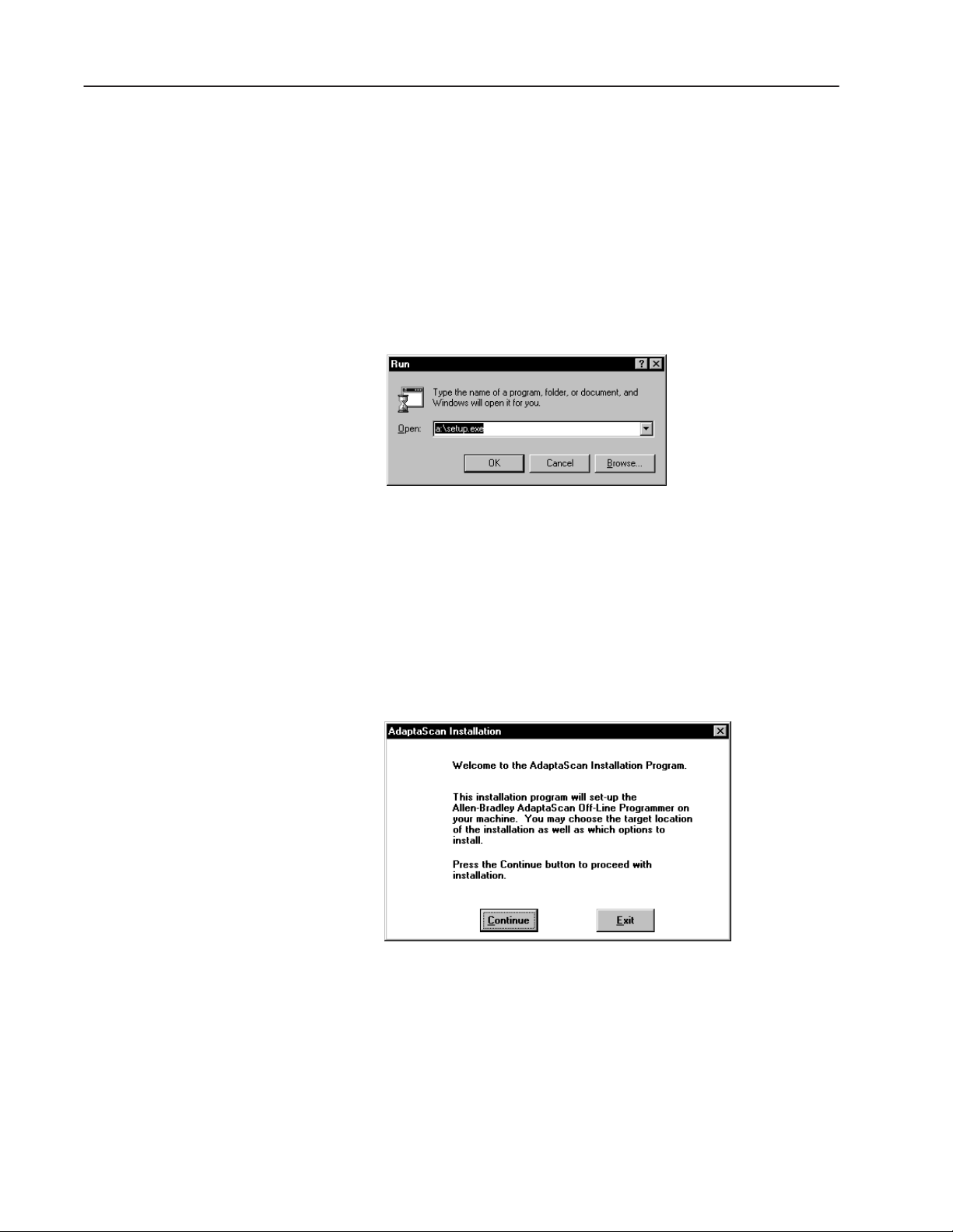
2. In the Program Manager window, choose Run from the File
menu.
The Run dialog opens.
3. In the command line box, type the drive letter of the drive
containing the AdaptaScan diskette followed by a colon and the
word setup.
For example, type a:setup
Then click OK or press
The installation begins. You are prompted to continue or exit the
installation.
ENTER.
Publication 2755-838
Page 13
1–3Installation
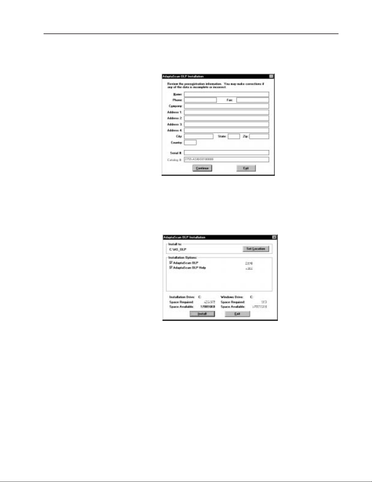
4. Click Continue to proceed with the installation.
You are prompted to verify/provide registration information.
5. Enter the registration data. Verify the software serial and catalog
number with the label on the software diskette. Click Continue
to proceed with the installation.
You are prompted for the location of files to be installed.
We recommend that you use the default installation path. To
change the installation drive or file name, click the Set Location
button.
6. Click the Install button to proceed with the installation
You are shown the progress of the installation. Insert disk #2
when requested.
A message indicates when the installation is complete.
Publication 2755-838
Page 14
1–4 Installation
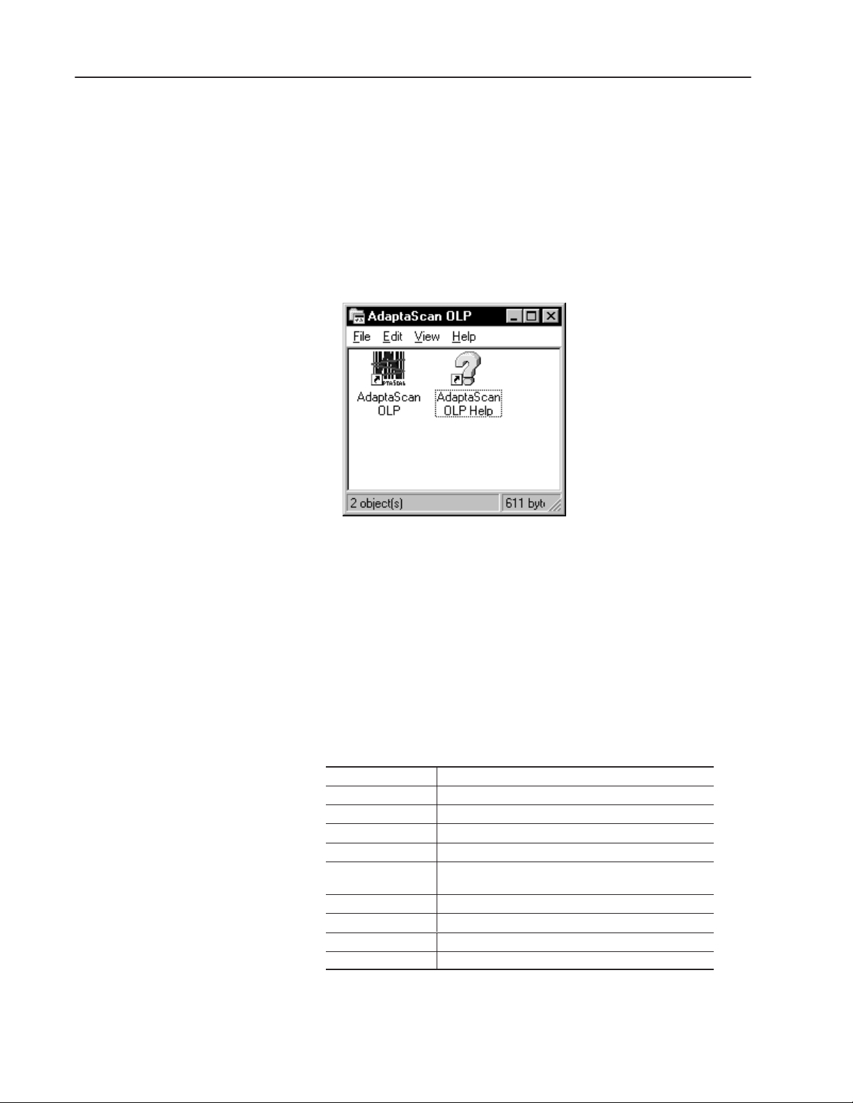
AdaptaScan Installation Summary
The default AdaptaScan installation:
• Copies files to disk under the target drive and directory
(C:\AS_OLP) or the location specified during installation.
• Adds ”AdaptaScan Off–Line Programmer” to registry
• Adds AdaptaScan OLP to the Windows Start menu
• Creates an AdaptaScan group containing icons for AdaptaScan
software and the Windows help file.
Registering AdaptaScan Software
Please take time to complete and send in the registration card you
received with AdaptaScan software. Registering entitles you to:
• automatic notification of upgrades and revisions to AdaptaScan
software
• technical assistance
AdaptaScan Installation Files
File Function
AB.SYS User information provided during installation.
ADAPTASC.HLP AdaptaScan help system.
ADAPTASC.CNT AdaptaScan help contents.
ADPTSCN1,2,3.EDS Contains product information for DeviceNet Manager.
APPGUIDE.DBF Database containing example projects from the
AdaptaScan Application Guide.
APPGUIDE.ID1 Index for database.
OLP.EXE AdaptaScan software executable.
SNEXxxxx.BIN Contains firmware code for Reader.
SNEXxxxx.INI Reader firmware update file.
Publication 2755-838
Page 15
1–5Installation
Downloading Firmware
Each Reader is shipped with manufacturing firmware installed.
You must download the release firmware prior to programming the
Reader. All the devices on the same network must have the same
firmware installed.
Note: Download firmware with a computer connected directly to
the Reader configuration port.
ATTENTION: Do not download firmware while the
scanner is on a DeviceNet master/slave network or you
!
will cause unrecoverable damage to the scanner.
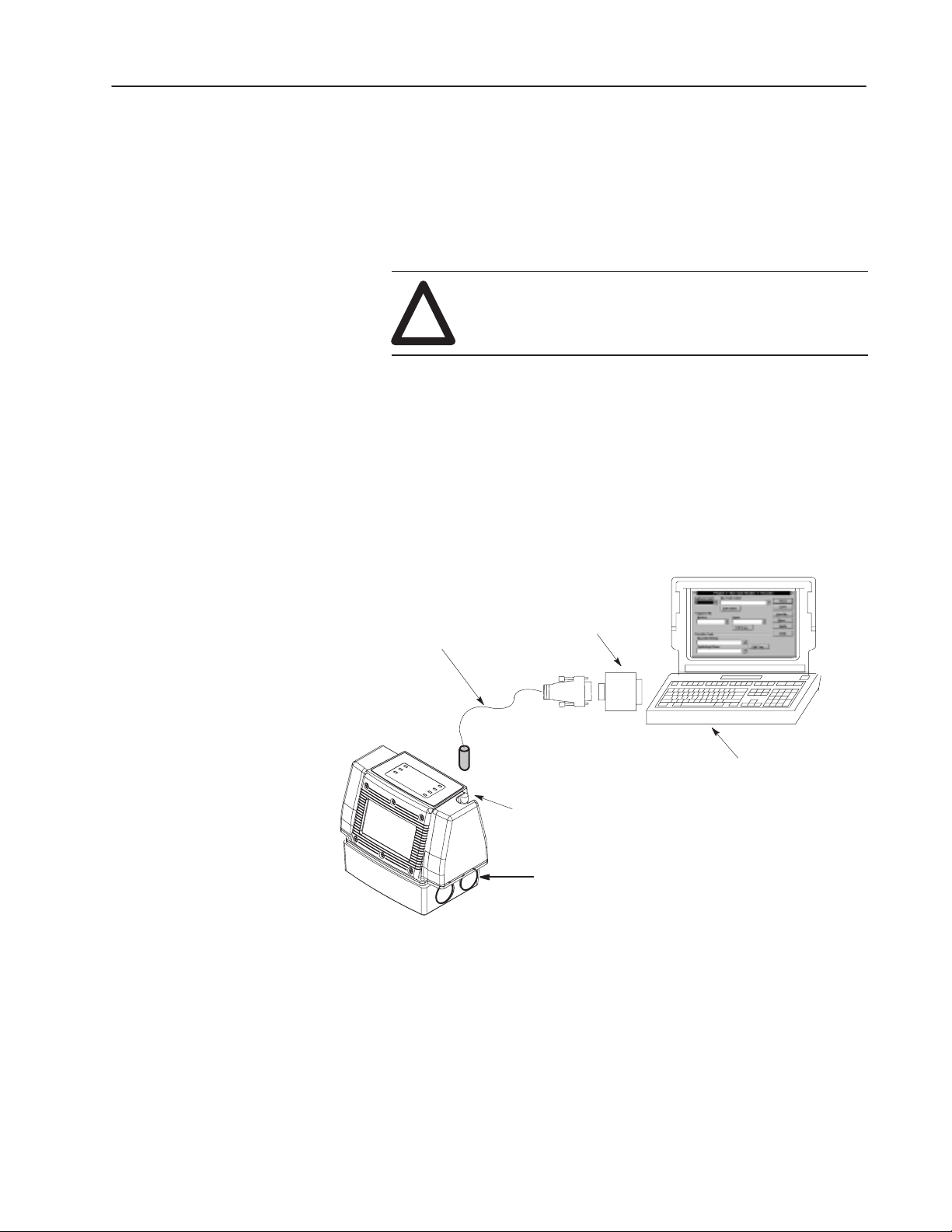
Connect Configuration Cable
The configuration cable connects the configured communications
port (see Preferences, page 2–18) of the computer running
AdaptaScan software to the Configuration Port Connector of the
Reader. Downloads may also be done through the the Reader serial
communication ports when scanner protocol is selected (see page
8–6).
Configuration Cable
(Catalog No. 2755-NC48 Series B Reader
2755-NC43 Series A Reader)
Circular Connector
Make Power Connections
After connecting the configuration cable, you can connect power to
the wiring base. The Reader User Manual (Publication 2755-837)
contains wiring diagrams and instructions.
D Connector
4 Pin Female
Configuration
Port Connector
9 to 25 Pin Adapter
may be required
9 Pin Male
Personal Computer
Connect power, refer to Reader
User Manual (Publication 2755-837)
Publication 2755-838
Page 16
1–6 Installation
Verify DeviceNet Address
The Reader is shipped with a default DeviceNet address of 63.
Verify that the DeviceNet address is still set at 63.
1. From the Windows Start menu, select Programs>AdaptaScan
OLP>AdaptaScan OLP.
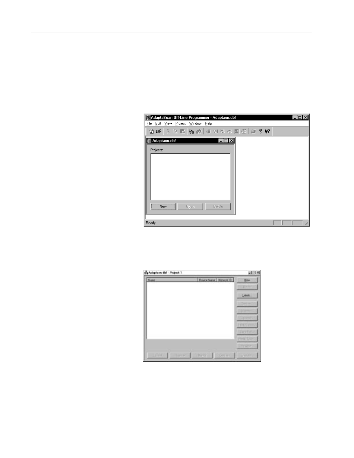
The database dialog opens.
2. Click the New button.
The AdaptaScan project window opens.
Publication 2755-838
Page 17
3. From the Communications menu, select Go-Online.
The Reader will be detected (if properly connected) and displayed
in the project window.
Note: The Query dialog may be displayed when you go on-line
(depending on your preference settings). Refer to page 2–19.
1–7Installation
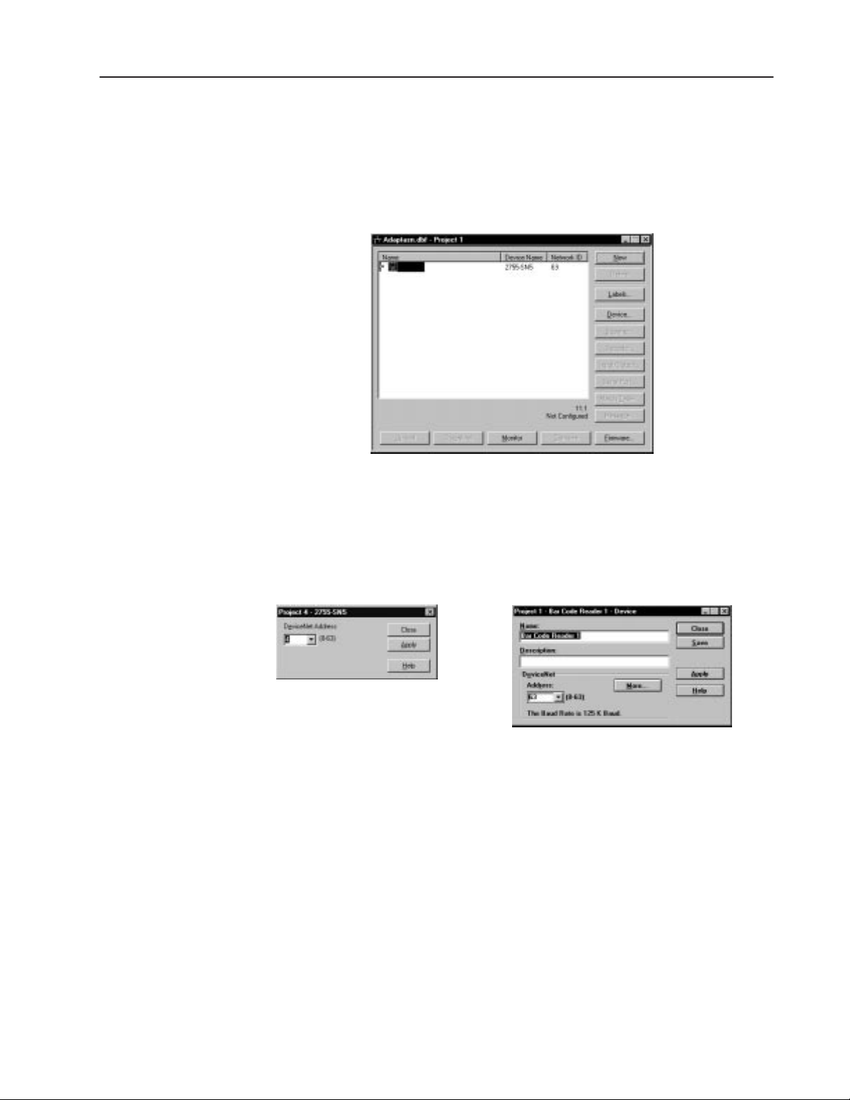
4. If the address displayed is not 63, change the Reader address by
clicking the Device button.
The Device dialog opens showing the current address.
If the Device is online but not in the project
database, the following dialog is displayed:
5. Change the address and click Apply.
If the Device is online and in the current project
database, the following dialog is displayed:
Publication 2755-838
Page 18
1–8 Installation
Download the Firmware to the Reader
1. Check that Reader is properly connected to your computer (using
configuration cable) and has power applied (refer to page 1–5).
2. Select Preferences from the View menu.
SNEXaaaa.ini
3. Make sure the communications channel is set to Configuration
Port.
4. From the Communications menu, select Go-Online.
The Reader will be detected (if properly connected) and displayed
in the project window.
Note: The Query dialog may be displayed when you go on-line
(depending on your preference settings). Refer to page 2–19.
5. From the Project window (see page 1–6), highlight the Reader
name and then click the Firmware button.
The Open dialog is displayed allowing you to enter or browse to
the firmware file you want to download.
Select .ini
Firmware File
aaaa = Version Number
SNEXaaaa.ini
6. Select the firmware file you want to download and click OK.
The following messages appear as the firmware is downloaded.
Downloading will take several minutes. During this time the
Module LED will flash red.
Publication 2755-838
Resetting. Please Wait . . .
Sending. Please Wait . . .
7. The messages disappear when the download is complete.
You are ready to create a Reader configuration.
Page 19

Chapter Objectives
Working with Projects
This chapter contains the following sections:
Section Page
Running AdaptaScan Software 2–2
What is a Database File? 2–3
What is a Project? 2–3
Opening a Project 2–3
Project Window 2–4
AdaptaScan Dialogs 2–8
Saving a Project 2–12
Closing a Project 2–13
Deleting a Project 2–13
Entering Project Name, Description, and Baud Rate 2–17
Selecting Preferences 2–18
Help 2–20
Chapter
2
Page 20
2–2 Working with Projects
Running AdaptaScan Software
AdaptaScan software opens like any other Windows 95 application.
To start AdaptaScan software:
1. From the Windows Start menu, select Programs>AdaptaScan
OLP>AdaptaScan OLP or double-click the AdaptaScan OLP
icon.
The AdaptaScan window opens with the database dialog:
The AdaptaScan Off-Line Programmer window is your workspace
for creating projects.
Publication 2755-838
Page 21
2–3Working with Projects
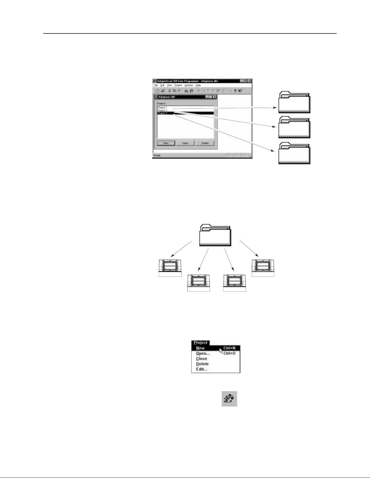
What is a Database File?
What is a Project?
A database file provides a method of organizing projects. Each
database file may contain one or more projects. From the File menu
you can open existing or create new database files.
Project File
Project File
Project File
Each Reader configuration is associated with a project. Each project
contains one or more Reader configurations. If using DeviceNet or
DH-485 communications, each project also defines one DeviceNet or
DH-485 network.
Opening a Project
Project File
Reader 1
Reader 2 Reader 3
Reader 4, . . .
There are two methods of creating a new project.
• From the Project menu, select New.
• Click the New Project tool on the tool bar.
The Project window opens allowing you to define a Reader
configuration.
Publication 2755-838
Page 22
2–4 Working with Projects
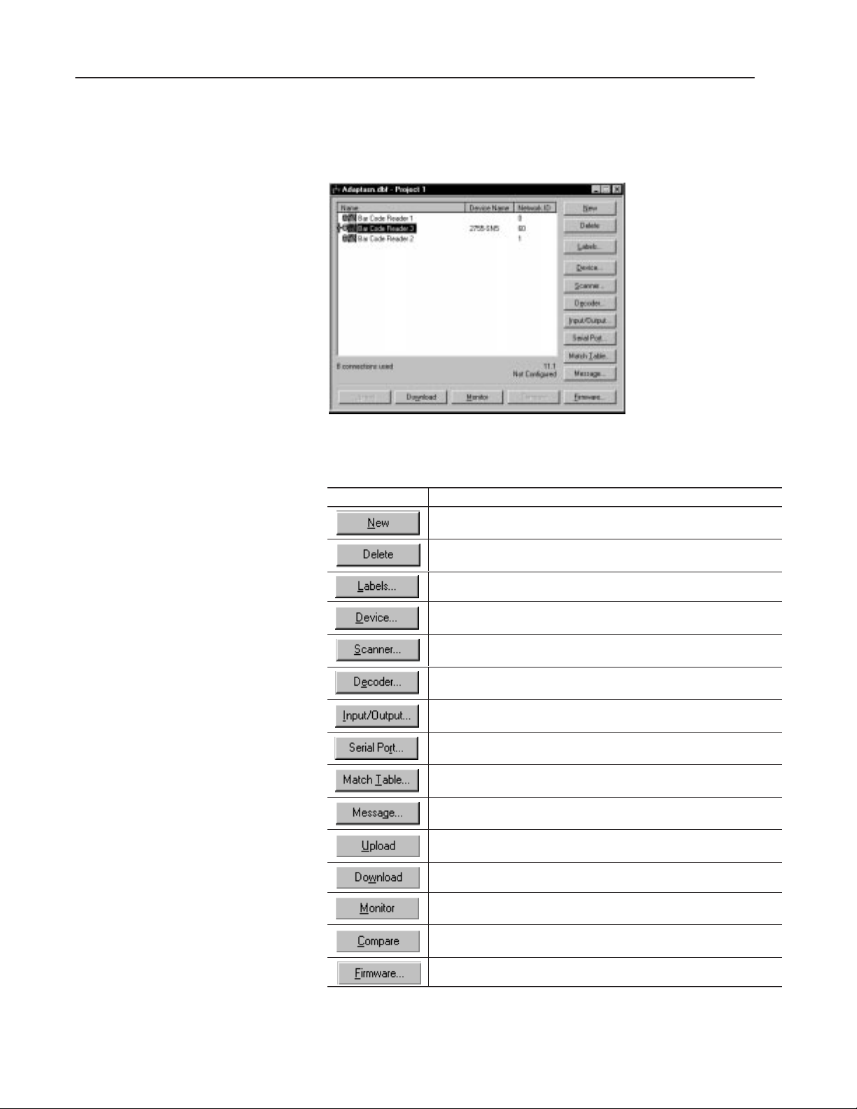
Project Window
Creating a Reader configuration starts with the Project window.
All of the basic configuration options are accessed from buttons.
Selecting a button opens the corresponding dialog.
The buttons on the Project window are defined below.
Select: To:
Create a new Bar Code Reader configuration (Bar Code Reader 1, Bar
Code Reader 2, Bar Code Reader 3, ...) in the Project window.
Delete the selected Bar Code Reader configuration from the Project window.
Define label setups and symbologies for Reader operation.
Define a unique name and enter a description for the Reader. Also de-
fines a DeviceNet address for the Reader.
Specify linear or raster scanning, how scanning is triggered, and accesses
the focus function.
Define when the Reader decodes data and what label is decoded. Also
defines the inter-symbol timer and performance indicator parameters.
Define the operation for package detector, discrete inputs, discrete out-
puts, timer and ASCII trigger commands.
Define communication parameters (RS-232, RS-485/RS422) and proto-
cols (ASCII, DH-485, DF1) for the Reader’s communication ports.
Define match table, package and counter functions for decoded
bar code data.
Define the format and content of messages sent to the host after bar
codes are decoded.
Transfer the configuration stored in a Reader to the currently opened
project in the AdaptaScan Software.
Downloads the highlighted configurations to the device or network.
View the operation of a single Reader or another Reader on the same
network.
Compare the Reader configuration within the project with the on–line
device.
Download new firmware to a selected Reader.
Publication 2755-838
Page 23
2–5Working with Projects
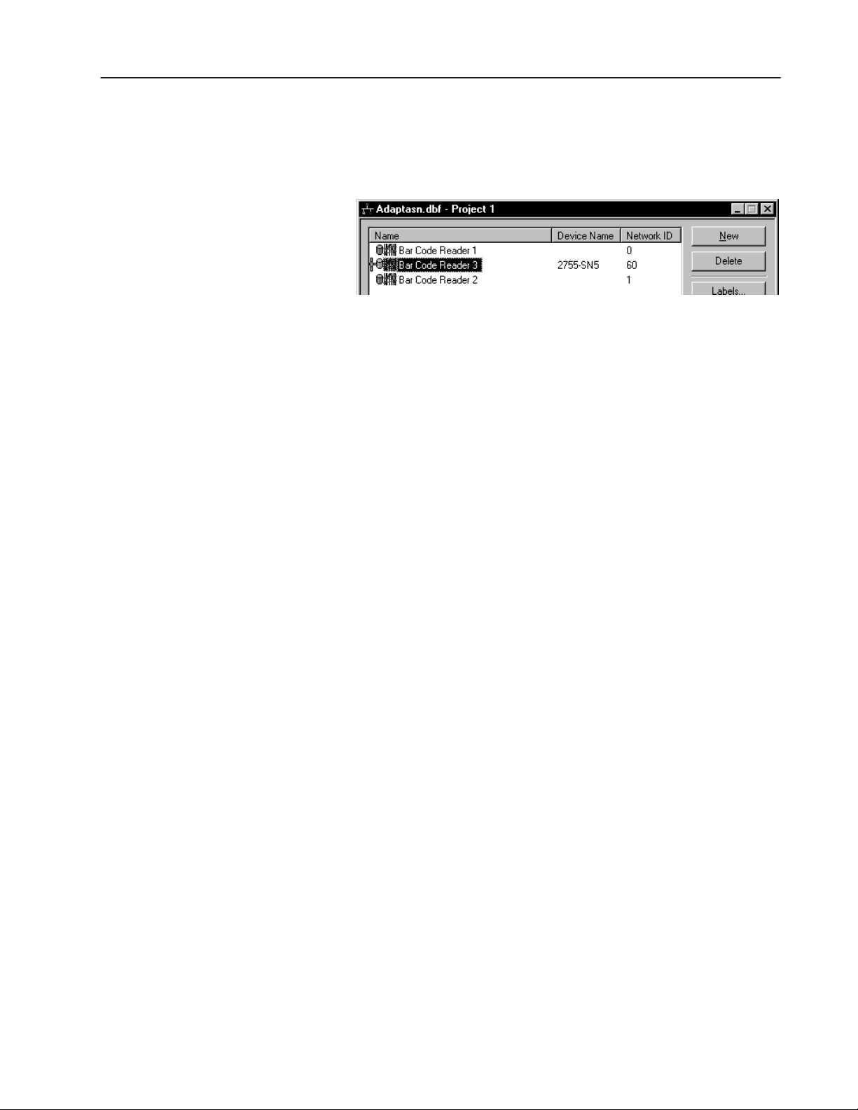
Existing Configurations
Any existing Reader configurations within the project are displayed
in the project window:
This display shows:
• Name - Reader name as specified on the Device dialog.
AdaptaScan software provides a default name of Bar Code
Reader 1, Bar Code Reader 2, etc.
• Device Name - read only field that displays the internally
configured name of the DeviceNet device (typically the catalog
number).
• Network ID - the node address of the device on the DeviceNet
network
Note: When you go on-line with the software, any devices that are
not part of the configuration but are present on the network will be
added to the display. Refer to Chapter 3 for a description of the
on-line functions.
Publication 2755-838
Page 24
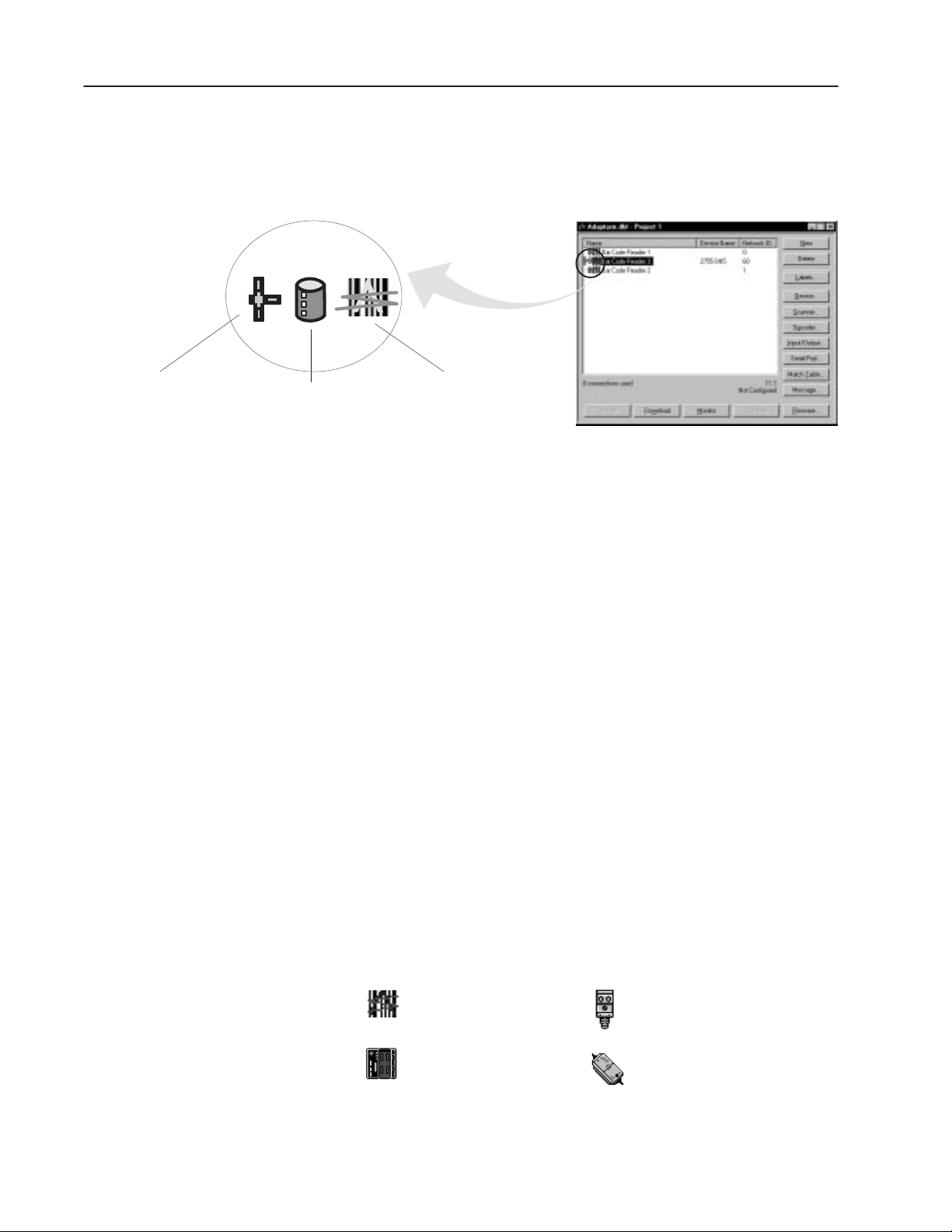
2–6 Working with Projects
Status
The project window status icons display the status of the Reader
connections and configurations.
Connection
Indicates device is on-line
Database
Indicates Configuration
is stored in the database
Connection
When displayed, indicates a connection was made to the device:
• Yellow (default) indicates that the AdaptaScan software does not
• Green appears after a Compare operation (see page 3–4) was
• Red appears after a Compare operation (see page 3–4) was
Database
When displayed, indicates that a database configuration exists for the
Reader. The color indications are the same as for the Connection
icon (see descriptions above) except the database icon will remain
yellow if a compare operation did not match the database.
Device Icon
Graphic representing
the type of device
have the information required to determine whether the device’s
configuration matches the configuration in the software database.
performed and the configuration of the on-line device matches the
database configuration.
performed and the configuration of the on-line device does not
match the database configuration.
Publication 2755-838
Device Icon
Displays the icon associated with the device. Here are some
common device icons:
= AdaptaScan Reader
= SDN Scanner Card
= PhotoEye photo-electric detector
= KFD DeviceNet Personal
Computer Interface
Page 25
2–7Working with Projects
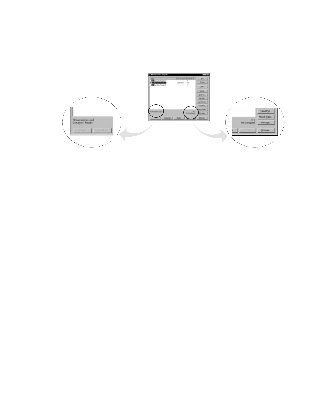
Information Lines
There are two areas on the project window that provide information
about a highlighted Reader configuration.
Connections per Reader / Description Field Version Number / Compare Status
Connections Per Reader / Description
The total number of connections is displayed on the project dialog
along with a device description. The description displayed is entered
on the Device dialog description field.
Each Reader has a minimum of 7 and a maximum of 64 connections.
A connection is an AdaptaScan object that moves data both
internally and between Readers. For example, when Package Detect
is specified as the decode trigger, a connection moves data from the
package detect input to the decoder. If the Package Detect is from
another Reader, each of the Readers use the connection object.
Important: You will not be allowed to download a configuration
with more than 64 connections in a Reader. A warning message is
displayed. However, you can still read old databases with more than
64 connections. You will need to reduce the number of items that
use connections before downloading the configuration. Some items
that use connections are match fields, inputs and outputs.
Version Number / Compare Status
The first line shows the firmware version number of the Reader. The
second line shows the compare status in a text format and matches
the status shown by the connection and database status icons (see
previous page).
Publication 2755-838
Page 26
2–8 Working with Projects
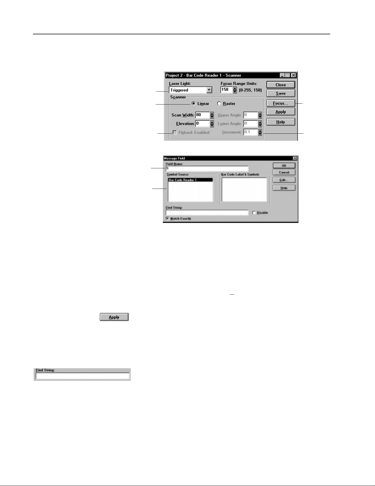
AdaptaScan Dialogs
AdaptaScan software uses dialog boxes to request information and
set operating parameters.
Drop-down List Box
Radio Button
Check Box
Text Box
List Box
Command
Button
Spin Control
To move around a dialog box:
• Move the mouse pointer to field and click the left mouse button.
• Or press TAB to move forward through fields and SHIFT+TAB to
move backward through fields.
• Or press the ALT key and the underlined letter of a field name.
For example, to move to the L
aser Light field, press ALT+L.
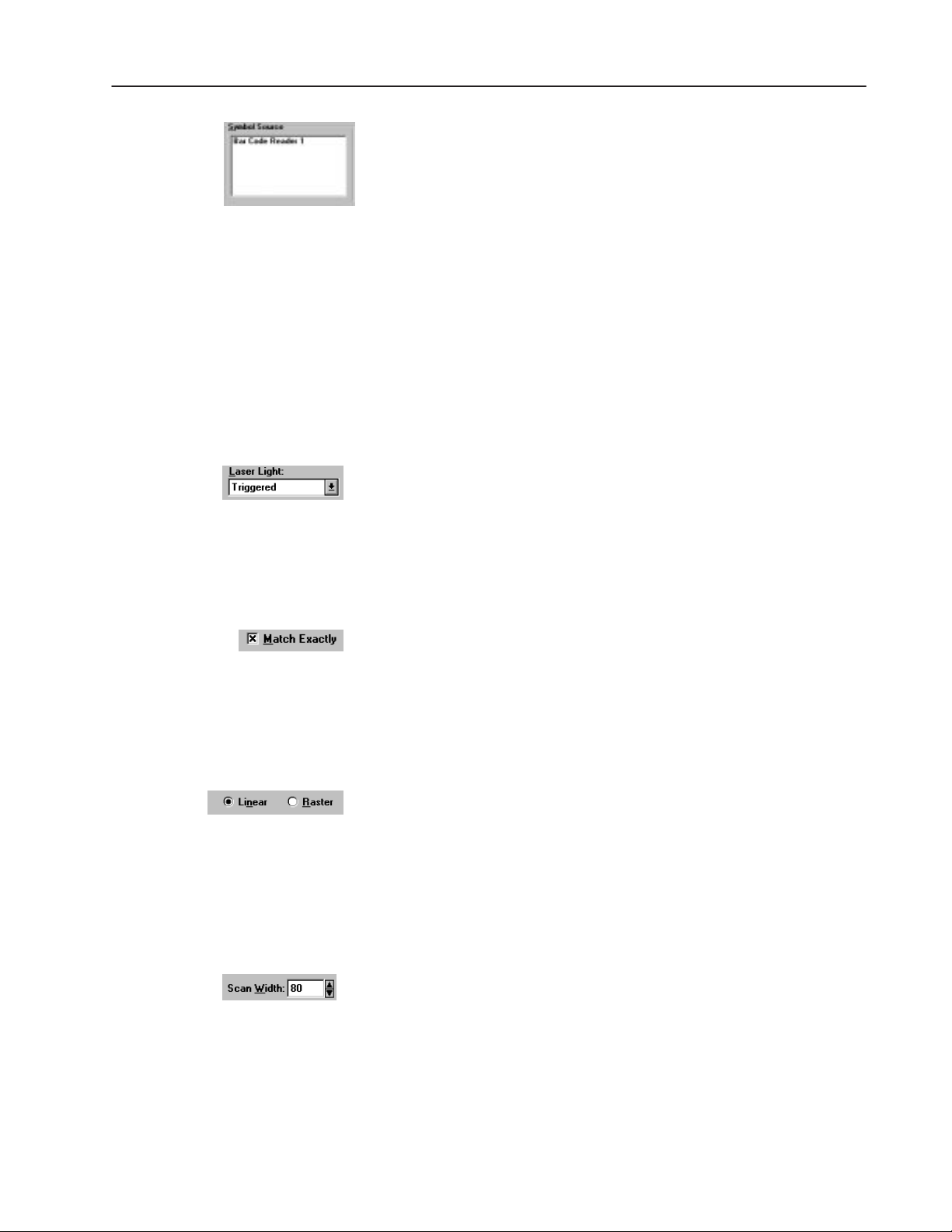
Command Buttons
Rectangular areas in the dialog box that look like buttons you can
push. When you click a command button, it presses like a real push
button.
Text Boxes
Text boxes are rectangular boxes in which you type text. Sometimes
these boxes contain text or a value, sometimes they’re empty.
The mouse pointer changes to an
box. Place the pointer where you want to start typing and click the
left mouse button. To replace all text, double-click in the text box
and type the new text.
I-beam when positioned over a text
Publication 2755-838
Page 27
2–9Working with Projects
List Boxes
This is a box with a list of items. To select an item from a list, click
on the item. A scroll bar appears beside the list box if there are more
items than can fit inside the box.
You can also use the arrow keys to select an item in the list. Press
TAB until you get into the list box. Then, press the UP or DOWN
ARROW
keys to select the item you want.
Some list boxes let you select multiple items. To select
non-consecutive items, click the first item, press and hold down the
CTRL key, then click the next item(s). To select consecutive items,
click the first item, press and hold down the
SHIFT key, then click the
last item. To deselect a range, click the first item in the list.
Drop-down List Boxes
These are text boxes with an underlined down-arrow beside them. If
you click inside the text area or click on the down-arrow, the list
drops down. When you select an item from the list, the list
disappears.
Check Boxes
Square boxes that contain an X or are blank. Check boxes are used
to select or clear an option. An X in the box means the option is
selected. A blank box means the option is not selected (it’s cleared).
Click the box to toggle the option on or off.
Radio Buttons
Circles that contain a solid dot or are blank. Radio buttons come in a
group. When you click one button in a group, it clears any other
option that was selected. A solid dot in the button means the option
is selected. When an option is not selected, the radio button is clear
(no dot).
Spin Controls
Small text boxes with up-down arrows at the right. Spin controls are
used to select sequential numbers. Click the up arrow to increase the
number or click the down arrow to decrease the number. Or you can
click in the box and enter a number.
Publication 2755-838
Page 28
2–10 Working with Projects
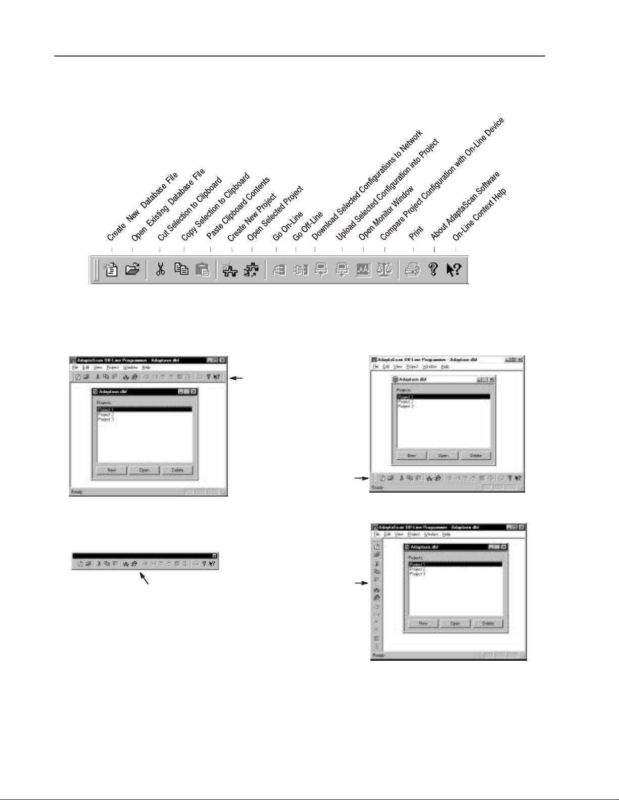
AdaptaScan Tools
Turn the tool bar view on or off from the View menu.
The tool icons provide shortcuts to the following menu items:
Move the toolbar to any side of the window or detach the toolbar and
place anywhere on your screen by clicking on and holding down the
mouse key while dragging the toolbar.
Detached
Default Position
Bottom Position
Side Window
Publication 2755-838
Page 29
Tool Summary
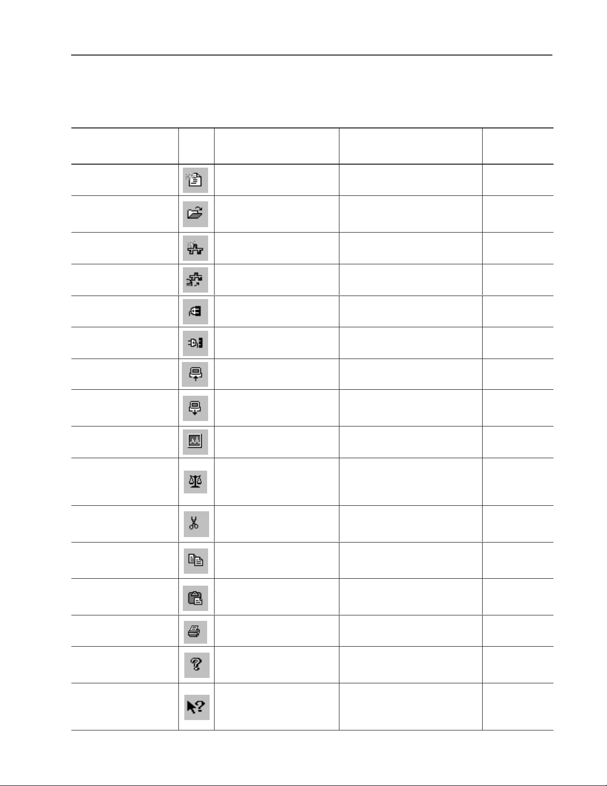
The following provides a brief summary of the AdpataScan tools.
2–11Working with Projects
Tool
Create New Database File >New
Open Existing Database File >Open
Open Selected Project Project >Open
Create New Project Project >New
Go On-Line On-Line Tools >Go On-Line
Go Off-Line On-Line Tools >Go Off-Line
Upload Selected
Configuration into Project
Download Selected
Configurations to Network
Icon
On-Line Tools >Upload
On-Line Tools >Download
or Select
from menu:
Description
Creates a database file that will contain
project configuration files.
Opens window allowing you to select an
existing database file (.dbf) containing
project configuration files.
Opens the project currently selected in
the AdaptaScan database file window.
Creates a new project within the
currently open database file (.dbf).
Connects the programming computer to
the network.
Disconnects the programming computer
from the network.
Uploads the configuration stored in the
selected device to the current project.
Downloads the selected Reader
configuration(s) to the Readers on the
network.
For additional
information,
see page:
2–3
2–3
2–3
2–3
3–2
3–2
12–3
12–5
Open Monitor Window On-Line Tools >Monitor Opens on-line monitor window. 3–5
Compare Project
Configuration with
On-Line Device
Cut Selection to Clipboard Edit >Cut
Copy Selection to Clipboard Edit >Copy
Paste Clipboard Contents Edit >Paste
Print File >Print
About AdaptaScan Software Help >About Off-Line Programmer
On-Line Context Help Help >Contents
On-Line Tools >Compare
Compares the configuration database of
the currently selected Reader to the
actual configuration stored within the
Reader.
Removes the currently selected item
from the dialog or window and places
the item on the clipboard.
Copies the currently selected item from
the dialog or window and places the
copy on the clipboard.
Pastes the last item placed on the
clipboard to the currently selected
location.
Opens the print dialog that allows you to
print out an application report.
Opens a dialog showing the software
revision and serial numbers along with
other software information.
When selected, displays a pointer. this
pointer may be moved to an area on a
dialog or menu and clicked for help
about the item.
3–4
2–14
2–14
2–14
13–2
2–20
Publication 2755-838
Page 30
2–12 Working with Projects
Saving a Project
Project information is saved as you configure each dialog box.
AdaptaScan dialog boxes have one or more of the following buttons.
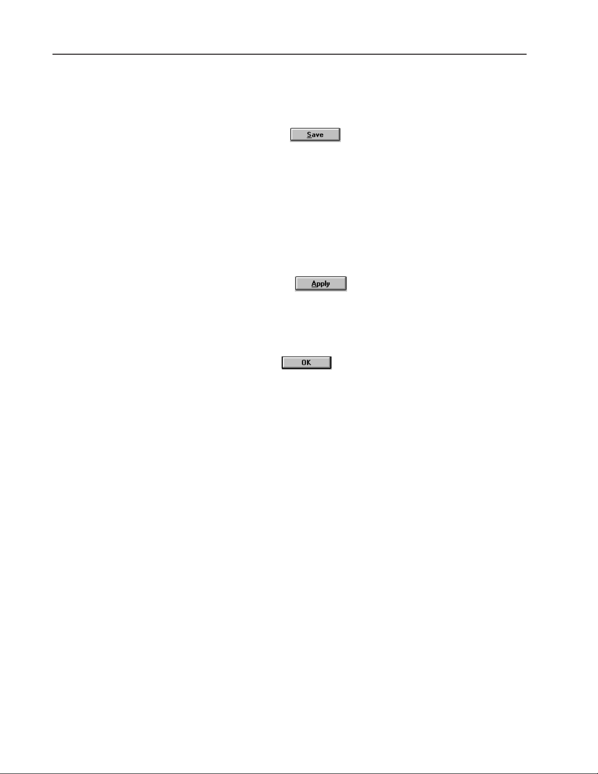
Save Button
Saves the dialog information. If you close a dialog without saving,
you are prompted:
Changes have been made. Do you want to save these changes
before closing?
If you select No, all changes to the dialog (and associated dialogs
accessed from the dialog) are deleted. Selecting Yes saves changes.
Apply Button
Sends the dialog data to the specified Reader. Use Apply when
making changes to the Scanner or Device dialogs while online.
OK Button
Accepts the data within the dialog box. The dialog information is
saved on the previous dialog (after selecting OK).
Publication 2755-838
Page 31

2–13Working with Projects
Closing a Project
This section shows how to close a project. When closing a project,
use one of the following methods. You are prompted to save
information if changes were made but not saved.
• With the project you want to close as the active window (or icon),
select Close from the Project menu.
• Or select Close from the control menu on the project window.
Control Menu Box
The Project window closes but the AdaptaScan Off-Line
Programmer window remains open.
Deleting a Project
With the project you want to delete as the active window (or icon),
select Delete from the Project menu.
You are prompted:
Are you sure you want to delete (Project Name).
After deletion, there is no way to recover it.
Select Yes to delete the project. When a project is deleted, all project
data is deleted from the program database and cannot be restored.
Select No to cancel the delete function.
Publication 2755-838
Page 32

2–14 Working with Projects
Using Cut, Copy and Paste
The following items may be cut, copied and pasted within and
between database files:
• projects
• Reader configurations
• match functions
• message fields
• labels
• symbols (can’t be copied)
The cut, copy, and paste icons and menu selections will only be
available where they can be used. Otherwise the icons will appear
grayed out.
Important: Cutting or copying and then pasting a Reader
configuration is different from importing/exporting Reader
configurations.
When an individual Reader configuration is pasted into a project,
only the original Reader’s configuration dialog boxes are copied and
recreated in the new project. Connections to and from the original
configuration are not recreated using Paste. Paste is useful when you
need to make a configuration similar to an existing configuration in
the currently open project or another project.
When you need to make an exact copy of a configuration, copy and
paste the entire project in the AdaptaScan database dialog or use the
import/export functions (see next page).
Publication 2755-838
Page 33

2–15Working with Projects
Importing/Exporting Reader Configurations
Using the import/export functions you can transfer exact copies of
Reader configurations between projects. The imported/exported
configurations maintain the internal and external connections (see
page 2–7 for a description of connections).
To import a Reader configuration into a project:
1. Open the project you want to import the configuration file into.
2. From the File menu, select Import.
The Import Configuration dialog is displayed.
3. Enter the path>filename of the Reader configuration you want to
import (.cfg file).
4. Click Open to import the Reader configuration into the project.
Publication 2755-838
Page 34

2–16 Working with Projects
To export a Reader configuration from a project:
1. Open the project that contains the file being exported.
2. Highlight the Reader configuration you want to export.
3. From the File menu, select Export.
The Export Configuration dialog is displayed.
4. Select the directory in which you want to place the Reader
configuration.
5. Click Save to export the Reader configuration. The file will
appear in the directory with a .cfg extension.
Publication 2755-838
Page 35

2–17Working with Projects
Entering a Project Name, Description, and Baud Rate
AdaptaScan software creates projects with a default name (Project 1,
Project 2, ...) and a default DeviceNet baud rate of 125K. To rename
a project, enter a project description or change the baud rate, open
the project you want to edit. With the project as the currently active
window, select Edit from the Project menu.
The Project dialog opens.
Enter a new project name and description. Select a baud rate that is
compatible with the DeviceNet network on which the Readers are
communicating.
Publication 2755-838
Page 36

2–18 Working with Projects
Preferences
The Preferences dialog allows you to specify options related to
computer communications. With the project as the currently active
window, select Preferences from the View menu.
The Preferences dialog opens.
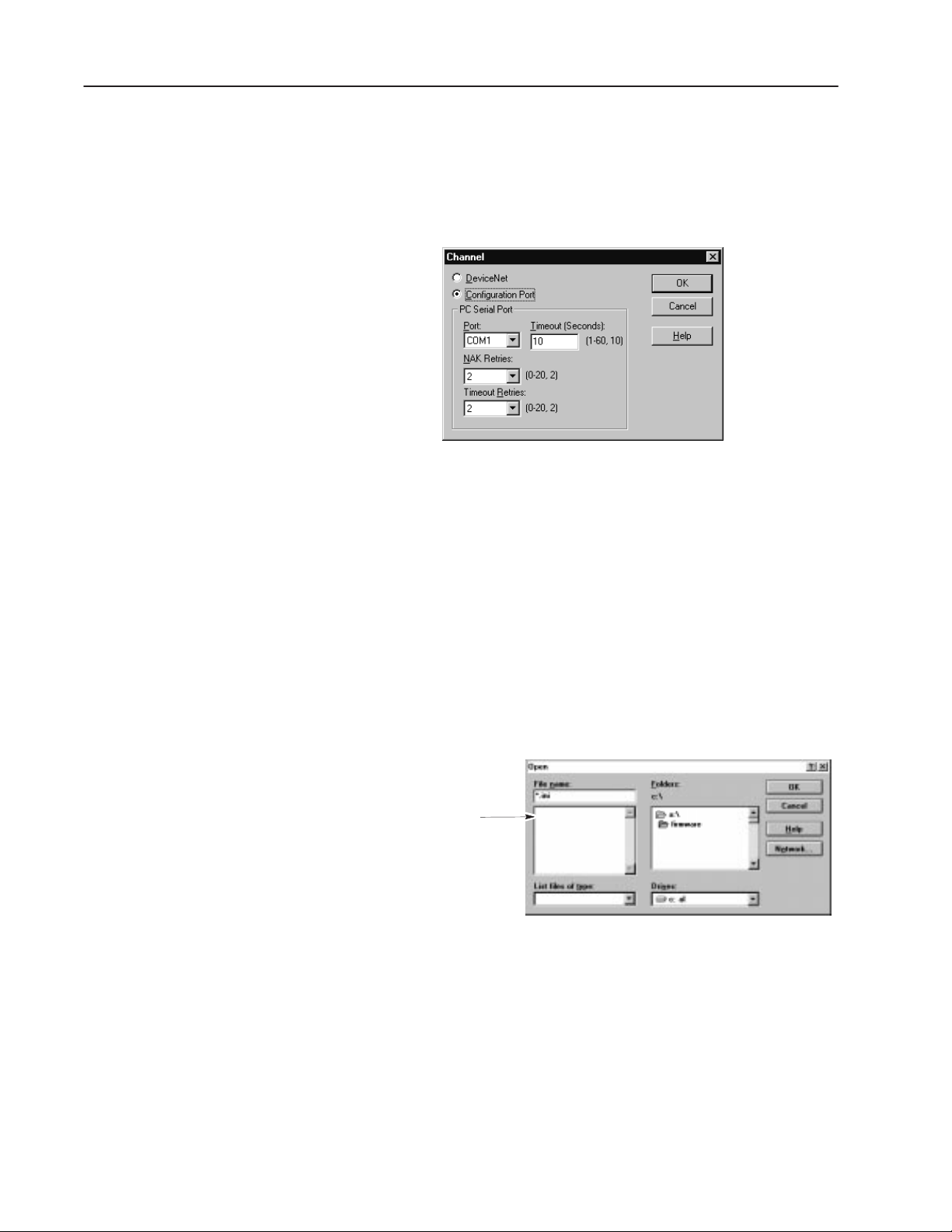
Select: To:
DeviceNet
Configuration Port Specify a direct connection to a Reader’s configuration port.
Port Specify the communications port on your computer used to
Timeout
(Seconds)
NAK Retries Enter the number of times your computer will accept a NAK
Timeout Retries Enter the number of times your computer will attempt to estab-
Select DeviceNet to communicate with a Reader through a
DeviceNet network. A DeviceNet communications card and
driver software must be installed on your computer.
This is the default setting.
configure the Reader. The options are COM1 through COM9.
Enter the amount of time your computer will wait for a response
before a timeout occurs. Enter a value between 1 and 60, the
default is 10.
(negative acknowledgement) before a communications fault
occurs. Enter a value from 0-20, the default is 2.
lish communications after a timeout. Enter a value from 0-20,
the default is 2.
Publication 2755-838
Page 37

2–19Working with Projects
Network Query Preferences
The Query dialog specifies the network addresses that are checked
when the AdaptaScan software checks the network. By specifying
just the addresses that need to be read, you can speed up network
operations.
The Query dialog is displayed when you:
• select Query from the View menu
• select Go On-Line from the Communications menu
• select Refresh from the Communications menu
Specify the network address you want to check:
Select To:
All
Displayed Check only the connections displayed in the project window
Selected Check only the connections displayed and highlighted in the
Specified Check only the addresses listed.
Check all addresses (0 to 63).
(see page 2–4).
project window (see page 2–4).
To disable the Query dialog from displaying when you use on-line
tools, uncheck the checkbox on the bottom of the dialog. You can
still access the dialog from the View menu after unchecking the box.
Publication 2755-838
Page 38

2–20 Working with Projects
Help
Both general and context sensitive Help is available. Access general
Help topics by choosing Contents from the Help menu.
Help feature How to use it
Contents Tab
Index Tab Choose to see an alphabetical list of topics.
Find Tab Choose to search for topics by keywords.
Choose to display the help content books.
Access context sensitive help by choosing the Help button available
on all dialogs. Or click the Help tool
and then the item you
want help for.
Publication 2755-838
Page 39

Chapter Objectives
Chapter
3
On-Line Communications
This chapter describes AdaptaScan online communications and tools.
Section Page
Going On-Line 3–2
Using the Compare Tool 3–4
Monitoring a Reader 3–5
Displaying LED Status 3–6
Displaying Counters 3–7
Displaying Scanner Performance 3–7
Displaying Bar Code Labels 3–9
Displaying Hardware Information 3–9
Page 40

3–2
Going On-Line
Go On-Line
The Go On-Line command establishes communications between the
AdaptaScan software and DeviceNet network using the
communication channel specified on the Preferences dialog (see
page 2–18).
To go on-line with AdaptaScan software:
1. Click the Go On-Line icon or select Go On-Line from the
Communications menu.
The project window will display the devices on the network along
with their catalog number and address.
Note: The Query dialog may be displayed when you go on-line
(depending on your preference settings). Refer to page 2–19.
Note: If you are connected to the DeviceNet network using the
Reader configuration cable, only AdaptaScan Readers on the
network are identified and displayed. When connecting using a
DeviceNet communications card and driver software on your
computer, all DeviceNet nodes on the network are identified and
displayed.
2. Highlight individual readers in the list to display the currently
loaded firmware revision and their configuration status.
Publication 2755-838
Page 41

3–3
When going on-line:
•
You can only be on-line with one project at a time. Use the Go
Off-Line command (Communications menu) when you want to
switch to another project.
• Upload, Download, Monitor and Compare functions are only
available for AdaptaScan Readers having the same major version
number as the AdaptaScan software (firmware version 11.XX or
greater)
• The Firmware button, for downloading firmware to a Reader, is
only available when the communications channel is set for
Configuration Port (direct connection using configuration cable).
• Use Refresh (Communications menu) to query the network and
update the display.
• Use Query (View menu) to display the Query dialog. The Query
dialog allows you to specify the network addresses read when
on-line functions are used. Refer to page 2–19. By only
checking the addresses that are required, you can increase the
speed at which network operations occur.
Publication 2755-838
Page 42

3–4
Using the Compare Tool
Go On-Line
Compare
The compare tool compares the calculated Cyclic Redundancy
Check (CRC) of the configuration stored in the project database with
the CRC of the configuration stored in the Reader. Compare is
useful when checking if a Reader’s configuration has been changed
to determine if an upload or download is necessary.
Note: Reader configurations cut and copied between projects may
not match when compared due to differences in the label
configurations between projects.
To use compare:
1. Make sure the software is on-line by clicking the Go On-Line
icon or by selecting Go On-Line from the Communications
menu.
Note: The Query dialog may be displayed when you go on-line
(depending on your preference settings). Refer to page 2–19.
2. Select the Reader configuration you want to compare with the
actual configuration stored within the Reader.
3. Click the Compare tool icon or select Compare from the
Communications menu.
Connection Icon Database Icon
If the Reader configuration has been compared and does not match
the configuration stored in the Reader, the connection icon appears
red.
If the Reader configuration has been compared and matches the
configuration stored in the Reader, the database and connection icons
appear green.
If a Reader configuration has not been compared to the configuration
stored in a Reader, the database and connection icons appear yellow.
Publication 2755-838
Page 43

The Monitor window displays the current operational status of a
Monitoring a Reader
Reader.
To monitor a reader:
3–5
Go On-Line
☞ The more information
monitored (the more check
boxes selected) the slower the
monitor window is updated.
1. Make sure the software is on-line by clicking the Go On-Line
icon or by selecting Go On-Line from the Communications
menu.
2. Open the monitor dialog by selecting the Monitor button on the
main Project dialog or by selecting Monitor from the
Communications menu.
The monitor window is displayed:
Package 1:90
Match1: 30
7003063081
7003063081
7003063081
Starts and Stops monitoring.
Resets counter to configured initial value.
Displays hardware information about Reader.
3. Select the items you want to monitor.
Closes the dialog.
Publication 2755-838
Page 44

3–6
Displaying LED Status
The LEDs area of the monitor display shows the status of specific
Reader operations. Select the LEDs check box to display the status
of Reader operations. The following tables show the LED
conditions and their meanings.
ATTENTION: Depending upon the amount of
information being monitored and network response
!
times, the LED status indicators may not reflect the
current status of the Reader. Do not rely on these
status indicators for important operating decisions.
On Symbol
Condition
Yellow Bar code symbol is being scanned and decoded.
Flashing Bar code symbol is being read at less than 100% rate.
Off Not reading a bar code symbol.
Trigger/Read
Condition
Yellow Decoder trigger is on.
Green Valid bar code symbol read.
Off No trigger or valid bar code symbol read.
Indication
Indication
I/O 1 and I/O 2
Condition
Yellow Corresponding input or output is in an On (closed contact) state.
Off Corresponding input or output is in Off (open contact) state.
Network
Condition
Green Normal DeviceNet operating state.
Flashing Green Communication link established but no data transfer.
Red DeviceNet communication fault detected.
Flashing Red One or more DeviceNet devices are not responding. Reader may
not be able to perform all of its configured functions.
Off No DeviceNet communications established.
Laser On
Condition
Yellow The scanning beam is On (active).
Off The scanning beam is Off (inactive).
Module
Condition
Green Normal operating condition. Power is applied to the Reader and no
faults have been detected.
Flashing Green Power-up initialization sequence or Reader is not configured.
Red
Flashing Red Minor fault (recoverable). Occurs when downloading new firmware.
Off
➀ For reference only. These indicators will not be visible if the condition causing them
occurs.
Processor fault (unrecoverable).➀
No power applied to Reader.➀
Indication
Indication
Indication
Indication
Publication 2755-838
Page 45

☞ Click the Reset Counters
Displaying Counters
Displayin
button to reset counters to
initial value.
3–7
The Counter area of the monitor display shows the values stored in
the package and match entry counters. Select the Counters check
box to display the counter values.
g
Scanner Metrics
The metrics area of the monitor display shows either:
• the decode margin (see definition below).
• the number of decodes during a trigger period (Counts)
Select either Dial or History
Select either Margin or Counts
You can display the Margin or Count parameters in either a Dial or
History format.
Dial
History
Scanner metrics are useful during:
• Initial Setup for making minor adjustments to the scan beam on
the Scanner dialog.
• Normal operation to identify small decreases in performance.
For example, if the number of reads drops significantly, label
quality may have degraded or the scan window may require
cleaning.
Publication 2755-838
Page 46

3–8
Margin
The scanner metric for margin is a measure of how clearly
distinguishable the different element sizes (bars and spaces) are in a
symbol. Margin is calculated every time a symbol is decoded. The
margin result is the tolerance remaining before the AdaptaScan can
no longer differentiate between wide and narrow elements.
Several factors affect the margin, including how well the
AdaptaScan is focused and the quality of the symbol. Assuming that
the AdaptaScan is properly focused, margin can be used for an
indication of trends in label quality. This is especially true for ink jet
symbols on cardboard cartons where low margins can occur because
of increasing ink spread.
Margin values may be returned in a host message (see page 10–2) or
used to trigger an output if the margin value falls below a user
defined level (see page 7–8).
Publication 2755-838
Page 47

3–9
Displayin
Labels
Displayin
g Bar Code
g
Hardware Information
Select the Bar Code Labels check box to display labels as they are
decoded. The data from each label displays on a separate line. Any
data formatting is not displayed.
123098
456987
051997
051997
071996
Select the Hardware Info button to display information about the
Reader such as series/revision, firmware version, boot version, and
catalog numbers of Reader and AdaptaScan software.
Publication 2755-838
Page 48

Chapter Objectives
Chapter
4
This chapter provides step-by-step instructions on how to configure
the Reader to scan and decode UPC-A symbols. This section
acquaints you with basic configuration and operation of the Reader
by stepping through a sample configuration.
Section Page
Configuration Description 4–1
What You Need 4–2
Connecting Power 4–3
Connecting the DL10 4–3
Installing the Reader 4–5
Connecting the Configuration Cable 4–5
Running the AdaptaScan Software 4–6
Downloading Firmware 4–9
Setting Up the Communication Port 4–7
Creating a New Project 4–8
Creating a New Reader Configuration 4–8
Defining the Label Setup 4–11
Configuring the Scanner 4–13
Positioning the Reader 4–13
Focusing the Reader 4–15
Configuring the Decoder 4–16
Configuring the Discrete Outputs 4–17
Setting the Timer 4–21
Setting the Serial Port 4–22
Defining a Package 4–19
Configuring Message Output 4–23
Downloading the Configuration 4–25
Monitoring Reader Operation 4–26
Dataliner Operation 4–26
Configuration Description
The sample configuration reads UPC-A labels. The Reader will
activate outputs 1 and 2.
• Output 1 energizes when a label is read.
• Output 2 energizes when a no-read occurs.
The monitor display shows the status of the Reader operation.
An optional Dataliner DL10 display receives and displays decoded
bar code data from the Reader’s RS-232 port.
Page 49

4–2 Getting Started
What You Nee
d
Personal Computer
Running Windows 95 or Windows NT
Configuration Cable
(Catalog No. 2755-NC48 Series B Reader,
2755-NC43 Series A Reader)
The sample configuration requires the following items. The
Datalinert DL10 and cable are optional. The DL10 is a slave
message display that displays any ASCII data that it receives from
the Reader. You can use the configuration software monitor function
to view decoded data if a DL10 or other display device is
unavailable.
AdaptaScan Bar Code Reader
(Catalog No. 2755-SN3, -SN5, -SN8)
9-to-25 Pin Adapter
Required for Computers with
25 Pin Communication Port.
(Purchase Locally)
AdaptaScan Wiring Base
(Catalog No. 2755-NB40, -NB41)
Test Bar Code Symbols
(Publication No. 2755-940)
Provided with this Manual
AdaptaScan Software
(Catalog No. 2755-ASN)
DL10 Communication Cable
2 Conductor Shielded Cable
(Belden 8303 or Equivalent)
Power Supply
(Catalog No. 2755-PW46, -PW47)
Dataliner
(DL10 with
120V Power Cord)
Optional Items
Wire & Small Slotted Screwdriver
For Connecting Power Supply
Publication 2755-838
Page 50

4–3Getting Started
Connectin
er
g Pow
230V AC Desktop
Power Supply
(Catalog No. 2755-PW47)
Before configuring the Reader, you must connect the
communications cable and provide power.
Power Connections
Connect the power supply to the Reader wiring base as shown below.
Note: This example uses unshielded wires for power connections.
Make sure you use shielded cable for the final installation as
described in the AdaptaScan Bar Code Reader user manual.
120V AC Wallmount
Power Supply
(Catalog No. 2755-PW46)
GND
+
-
V+
Can_H
Shield
Can_L
V-
Reader Wiring Base
Verify the connection by applying power to the wiring base and
observing the polarity LED. The LED should be green. If the LED
is red, the polarity needs to be reversed. Disconnect power from the
wiring base until the Reader is installed.
Publication 2755-838
Page 51

4–4 Getting Started
Connecting the
DL10 Slave
Use a two conductor shielded cable to connect the DL10 data display
to the RS-232 port of the Reader. The DL10 is optional. If you
don’t have a DL10, you can still view decoded data using the
configuration software monitor function.
Note: The data viewed on the monitor window does not necessarily
correlate with the data sent out of the serial port. The monitor
window displays unformatted data while the serial port data may be
formatted to contain other data such as replacement strings, source
ID, etc.
Dataliner DL10
Message Display
Dataliner
Communications Port
Connect to 120 VAC
Power Source
Publication 2755-838
Use Belden 8303
or equivalent
Tx
GND
RS-232 Port
Reader Wiring Base
Page 52

Installing the Reader
Connecting the
Configuration Cable
ower-up Sequence
4–5Getting Started
Carefully position the Reader on the wiring base. You don’t need to
tighten the screws for this sample application.
Screws
4 Locations
Don’t Tighten Screws
Wiring Base
Insulating
Cover
Use the configuration cable (Catalog No. 2755-NC48 Series B,
2755-NC43 Series A) provided with the AdaptaScan software to
connect the computer’s communication port to the Reader’s
configuration port. If the computer has a 25-pin connector, you need
a 9-to-25 pin adapter.
9-to-25 Pin Adapter
Configuration Cable
(Catalog No. 2755-NC48 or -NC43)
4 Pin Female
Circular Connector
P
Apply power to the Reader. On initial powerup, the Reader performs
may be required
9 Pin Male
D Connector
Personal Computer
Configuration
Port Connector
Power source required
See Reader user manual
(Publication No. 2755-837)
a series of self-diagnostic tests and LED tests (all LEDs flash).
Refer to table page 3–6 for a description of the LED indicators.
When the Module LED flashes and turns a steady or flashing green,
the powerup sequence is complete. The complete powerup sequence
takes a few seconds.
Publication 2755-838
Page 53

4–6 Getting Started
Running the
AdaptaScan Software
If you haven’t already done so, install the AdaptaScan software.
Software installation procedures are described in Chapter 1.
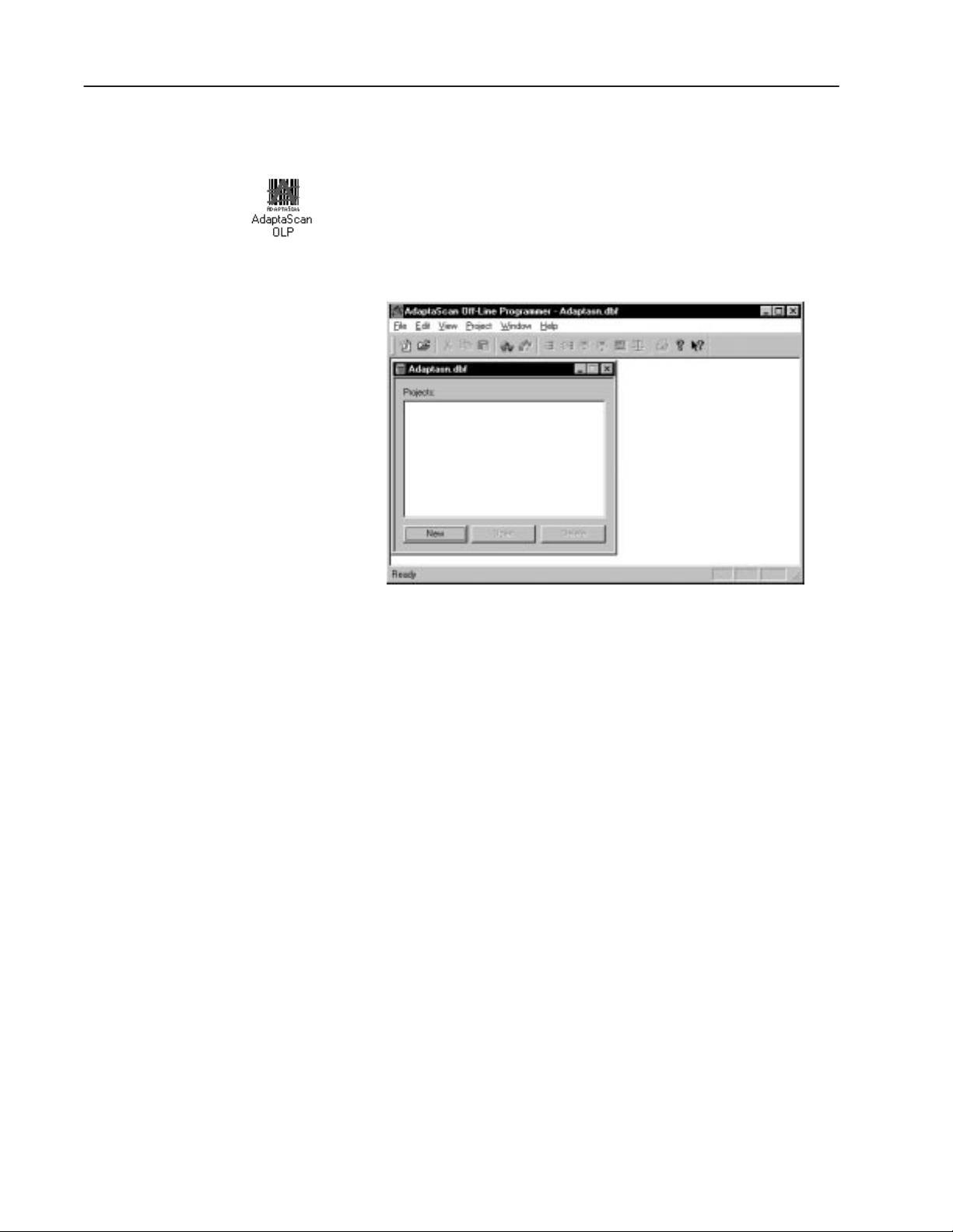
After installing the software, the AdaptaScan OLP group icon
appears in the Program Manager window.
To run the AdaptaScan software:
1. From the Windows Start menu, select Programs>AdaptaScan
OLP>AdaptaScan OLP.
The AdaptaScan window opens.
2. All configurations occur within the AdaptaScan window. Use the
dialog buttons and/or menu selections to access the AdaptaScan
software operations.
Publication 2755-838
Page 54

4–7Getting Started
Communications Setup
The Reader configuration port is set for 9600 Baud and cannot be
changed. This port is set by default to communicate with the first
port that is available on your computer.
If your computer is using a different communication port, change the
port by selecting Preferences from the View menu.
To change communication port settings:
1. Select Preferences from the View menu.
The Preferences dialog opens.
2. Select the communications port connected to the Reader.
3. Make sure that Configuration Port connection is selected.
4. Click OK to save changes.
Note: The Reader can also be connected to a Reader through a
DeviceNet network connection. A DeviceNet communications card
and driver software must be installed on your computer. If you are
using DeviceNet Manager Software (Catalog No. 1787-MGR) to
connect to an AdaptaScan Reader in a network, refer to the user
manual (Publication No. 1771-2.29). Select DeviceNet connection
on the Preferences dialog when using a DeviceNet network
connection.
Publication 2755-838
Page 55

4–8 Getting Started
Creating a Project
Creating a Ne
Reader configuration dialogs are accessed from the Project menu.
To create a project:
Select New from the Project menu or click New on the AdaptaScan
window.
The Project window opens with the default name of Project 1.
w
Reader Configuration
To create a Reader configuration:
From the Project 1 window, click the New button.
An application is created with the default name Bar Code
Reader 1. Applicable dialog buttons are enabled.
Publication 2755-838
Page 56

4–9Getting Started
Downloadin
are
g Firmw
If the Reader is being operated for the first time (out of the box), you
must download operating firmware.
The Reader is shipped with a default DeviceNet address of 63.
To download operating firmware to the Reader:
1. From the Communications menu, select Go-Online.
The reader will be detected (if properly connected) and displayed
in the project window.
Note: The Query dialog may be displayed when you go on-line
(depending on your preference settings). Refer to page 2–19.
Note Address
2. From the Project window, highlight the Reader name and then
Select .ini
Firmware File
aaaa = Version Number
click the Firmware button.
The Open dialog is displayed allowing you to enter or browse to
the firmware file you want to download.
SNEXaaaa.ini
Publication 2755-838
Page 57

4–10 Getting Started
3. Select the firmware file you want to download and click OK.
The following messages appear as the firmware is downloaded.
Downloading will take several minutes. During this time the
Module LED will flash red.
Resetting. Please Wait . . .
Sending. Please Wait . . .
4. The messages disappear when the download is complete.
You are ready to create a Reader configuration.
Publication 2755-838
Page 58

4–11Getting Started
Defining the Label Setup
This section shows how to specify what type of label(s) the Reader is
expected to decode. For the sample configuration, the Reader is
expected to decode an UPC-A symbol.
To define the bar code label setup:
1. From the Project 1 window, click the Labels button.
The Bar Code Labels dialog opens.
2. Click New to define a new label.
The Bar Code Labels dialog opens with a default name of Label
1 for the label setup.
3. Click the New button to specify the symbols the Reader expects
to find on a label.
Publication 2755-838
Page 59

4–12 Getting Started
The Bar Code Label Symbol dialog opens.
4. Make changes as shown below and then click OK.
1. Change
Name to UPC-A
2. Select
UPC-A
The Bar Code Label dialog shows UPC-A in the Symbols list. If
other symbologies were expected on the label, you would define
them in the same way.
3. Click OK
Publication 2755-838
5. Click OK to save the label definition.
The bar code label, Label 1, appears in the Bar Code Labels list.
6. Click Save and then Close to save and close the label definition.
You return to the Project 1 window.
Page 60

4–13Getting Started
Con
the
anner
figuring
Sc
This section configures the Reader for linear scanning.
Configure the scanner:
1. From the Project 1 window, click the Scanner button.
The Scanner dialog opens.
Select
Always On
Select
Linear
2. Select Always On from the Laser Light list.
Note: Only use the Always On setting for initial setup. When
installed in an application, you should set Laser Light to
Triggered.
3. Select Linear under Scanner options.
Before using the focus function, you must position the Reader so
that the scan beam crosses a UPC–A label. You can use the test
card (Publication 2755-940).
Publication 2755-838
Page 61

4–14 Getting Started
Position the Reader:
1. Place the test symbol approximately 12 inches (.3 meter) in front
of the Reader so that the scan beam crosses the symbol.
Observe
On Symbol
LED
Test Card
Make sure symbol
is slightly skewed.
2. Observe the ON Symbol LED on top of the Reader. When the
LED is illuminated, the Reader is scanning an enabled
symbology.
Note: The ON Symbol LED may not light (bar code symbol not
read) if the Reader is not focused correctly or the symbology is
not configured.
Adjust scan line elevation and width:
If the scan line does not completely cross the UPC-A symbol, adjust
the scan line elevation and width.
1. Increase or decrease the scan width and elevation.
2. Click Apply to send the new settings to the Reader, wait for the
changes to take affect.
3. Repeat adjustments until the scan line is crossing all of the
symbol.
Publication 2755-838
Page 62

4–15Getting Started
Use focus:
1. Click the Focus button to open the Focus dialog.
Select this
check box
2. Select the Set to Suggested Position check box and then click the
Start button.
As the Reader adjusts the focus from the shortest to longest focal
length, you may notice the scan beam change width. When
completed, the display shows the focus margin profile with
markers at the minimum and maximum range (red lines) and the
recommended setting (green line). The recommended setting is
at two-thirds of the margin up from the minimum setting. The
focus is automatically set at the recommended range units.
Margin Profile
Minimum Limit
Recommended Setting
Maximum Limit
3. Click OK to return to the Scanner dialog.
4. Click Save to save the scanner settings, then click Close.
You return to the Project 1 dialog.
5. ON Symbol LED illuminates.
Publication 2755-838
Page 63

4–16 Getting Started
Con
the Decoder
figuring
This section shows how to specify when and what labels are to be
decoded by the Reader.
To configure the decoding parameters:
1. From the Project 1 window, click the Decoder button.
The Decoder dialog opens.
The label name Label 1 should appear in the Bar Code Label list.
If the name doesn’t appear, you need to redefine the label setup.
Since the project contains a single Reader configuration, Bar
Code Reader 1 should appear as the trigger source for decoding.
1. Select Label 1
2. Select
Bar Code Reader 1
3. Select Timer
2. Select Timer from the Input list. Timer allows the Reader to
trigger decoding without an external input (package detect). This
is useful for simulating a package detector during setup.
3. Click Save and then Close to save the decoding parameters.
You return to the Project window.
Publication 2755-838
Page 64

4–17Getting Started
Con
figuring
the Discrete Outputs
The sample configuration turns on output 1 when a symbol is read
and turns on output 2 when a no-read occurs. You can turn on these
outputs using the match table and package output definitions.
To configure the discrete outputs:
1. From the Project 1 window, click the Match Table button.
The Match Table dialog opens.
2. Click the New button to define a match function.
The Match Functions dialog opens with a default Match Function
Name of Match 1.
1. Select Match Entry
2. Click Here to
Display Label Setup for
Bar Code Reader 1
3. Enter Match Rule:
4. Check Match
Exactly Box
3. Select Match Entry from the Functions list.
4. Select Bar Code Reader 1 from the Symbol Source box.
5. Make sure Disable
is not selected
Publication 2755-838
Page 65

4–18 Getting Started
The label setup defined for Bar Code Reader 1 is displayed in the
Bar Code Labels & Symbols box.
Select the UPC-A
Label Setup
5. Select UPC–A from the Bar Code Labels & Symbols box.
6. If you want the Reader to match a specific label, enter the symbol
data as the Rule.
7. Click the Outputs button to specify which output to activate
when a match occurs.
The Match Function Output dialog opens.
☞ Or double-click an available
output to add it to the list
of outputs.
8. From the Available Outputs: list, select Discrete Input/Output 1
and then click the Add >> button.
The Output To: list shows that Discrete Input/Output 1 is assigned
to the match function.
9. Click OK to return to the Match Function dialog.
10. Click OK to return to the Match Table dialog.
You have completed the configuration of the match table.
Publication 2755-838
Page 66

This section shows how to define a package based on the match
Defining a Package
entry definition (Match 1).
1. From the Match Table dialog, click the Package button.
The Packages dialog opens.
4–19Getting Started
2. Click the New button.
The Packages dialog opens with the default Package Name,
Package 1.
Select
No-Read Package
Select Match 1
3. From the Mode list, select No-Read Package.
4. Highlight Match 1 in the Match Functions box.
5. Click OK.
Publication 2755-838
Page 67

4–20 Getting Started
The Packages dialog opens with the created package definition.
Package Definition
6. Select the Output To button.
The Package Outputs dialog opens.
☞ Or double-click an available
output to add it to the list
of outputs.
7. From the Available Outputs: list, select Discrete Input/Output 2
and then click the Add >> button.
The Output To: list shows that Discrete Input/Output 2 is assigned
to the package definition.
8. Click OK to return to the Packages dialog.
9. Click OK to return to the Match Table dialog.
10. Click Save and then Close.
You return to the Project 1 window.
Publication 2755-838
Page 68

4–21Getting Started
etting the Timer
S
☞ Or double-click on Timer to
open the Timer dialog.
This section configures the timer that was selected as the trigger
source for decoding and scanning.
1. From the Project 1 window, click the Input/Output button.
The Input & Output dialog opens.
Select Timer
2. Select Timer and then click the Edit button.
The Timer dialog opens with a default timer name of Timer.
Cyclic Timer
On 1 Second
Off 1 Second
The dialog shows that the timer is set for cyclic operation, with a
specified On Time and Off Time.
3. Click OK to exit and return to the Input & Output dialog.
4. Click Save and then Close to save the timer definition.
You return to the Project 1 window.
Publication 2755-838
Page 69

4–22 Getting Started
etting the
S
Serial Port
This section describes how to configure the Reader RS-232 port
(inside wiring base).
To configure the serial port:
1. From the Project 1 window, click the Serial Port button.
The Serial Port dialog opens. Verify the following settings:
1. Select Terminal
2. Select
9600 Baud
3. Select 0 message
length (sends all
data regardless of
length).
4. Select
No Parity,
8 Data and
1 Stop Bit.
5. Select
RS-232 Connection
2. Click Save and then Close to save the serial port configuration.
You return to the Project 1 window.
Note: If using the DL10 Dataliner, make sure that the DL10
configuration is set to match the Reader serial port configuration:
Terminal Protocol
9600 Baud
No Parity
8 Data Bits
1 Stop Bit
Publication 2755-838
Page 70

4–23Getting Started
Con
figuring
Message Output
This section shows how to configure the Reader to send bar code
data out the RS-232 port to the Dataliner message display.
1. From the Project 1 window, click the Message button.
The Message dialog opens. Make the following edits:
1. Select Enable
2. Select Timer
2. Click the New button.
The Message Field dialog opens. Make the following edits:
1. Select Bar
Code Reader 1
2. Select UPC–A
Symbol
3. Leave blank
4. Check Match
Exactly box
5. Make sure Disable
is not selected
Note: If you leave the Find String blank and select Match Exactly,
all characters will be matched.
Publication 2755-838
Page 71

4–24 Getting Started
3. Click the Edit button.
The Message Field Edit dialog opens. Make the following edits:
1. Set length to 14
2. Leave blank
3. Enter NO–READ
as the Fail string
Note: If you leave the Pass String field blank, all of the decoded bar
code data is placed in the message string. You could enter a string
like Good Read that would be placed in the data message whenever
a UPC label is decoded. The Fail String NO-READ is placed in a
message when a label is decoded that does not match the content of
the Find String (see previous page).
4. Click OK to exit and return to the Message dialog.
5. Click the Format button on the Message dialog.
The Message Format dialog opens. Make the following edits:
1. Enter \n as
the header.
2. Enter \r as
the trailer.
3. Make sure
Serial Port
is selected.
Note: \n = Line Feed, \r = Carriage Return
6. Click OK to exit and return to the Message dialog.
Publication 2755-838
7. Click Save and then Close to save the message definition and
return to the Project 1 window.
Page 72

4–25Getting Started
Downloadin
g
the Configuration
This section shows how to download the Bar Code Reader 1
configuration to the Reader.
Verify the computer to Reader connections described on page 4–5.
To download the Bar Code Reader 1 configuration:
1. Select Go On–Line from the Communications menu.
The Reader will be detected and displayed in the Project window:
2. From the Project 1 window, verify that Bar Code Reader 1 is
selected.
3. Set the Reader address by clicking the Device button.
The Device dialog opens allowing you to change the address.
The Reader is shipped with a default address of 63.
4. If you want to change the address, click Apply to send the
address to the Reader.
It will take a few seconds for the address download to occur.
5. Click Save and then Close.
You return to the Project 1 window.
6. With the Reader configuration highlighted, click the Download
button to download the configuration to the Reader.
The following messages appear during the download.
Resetting. Please Wait . . .
Sending. Please Wait . . .
When the download is complete, the messages disappear.
7. Click the Scanner button and select Triggered for the laser light
control. Click Apply to send the changed setting to the Reader.
8. The Reader should now be turning the scan beam on and off at 1
second intervals.
Publication 2755-838
Page 73

4–26 Getting Started
Monitorin
g
Reader Operation
The Monitor window shows the status of the Reader while scanning
and decoding bar code labels.
To use the monitor display:
1. From the Project 1 window, click the Monitor button.
The Monitor dialog opens.
2. Select the LED, Metrics, Counters, and Bar Code Labels check
boxes. Click the Start button to begin monitoring.
Package 1:90
Match1: 30
7003063081
7003063081
7003063081
3. Move the bar code label to various distances and positions.
Observe the results. The Match counter increments each time the
symbol is read. Notice that when you move the symbol out of the
scan beam, the Package counter (set for no reads) increments
once for every trigger.
4. Click the Close button to exit the Monitor dialog and return to the
Project 1 window.
Publication 2755-838
Page 74

4–27Getting Started
Dataliner Operation
The DL10 message display should be displaying the UPC–A
symbols as they are decoded. Each symbol is preceded with a line
feed (\n header) and terminated with a carriage return (\r trailer).
Publication 2755-838
Page 75

Laser Caution
Chapter Objectives
Chapter
5
This chapter shows how to define scanner setup for the Reader.
Section Page
Laser Caution 5–1
Scan Patterns 5–2
Scan Adjustments 5–3
Setting up the Scanner 5–4
Focus Options 5–6
Setting the Focus 5–7
The Reader uses a low power visible laser diode. As with any bright
light source, you should avoid staring directly into the beam.
Momentary exposure to a CDRH Class II laser is not known to be
harmful.
ATTENTION: Laser Light: do not stare into the
beam. 660nm laser diode 1.0 milliwatt max output
!
Class II laser product.
Page 76

5–2
Scan Patterns
Picket Fence Orientation
The Reader performs both linear and raster scanning.
Linear Raster (with flyback)
The orientation of the Reader to the labels usually determines the
type of scanning required.
Step Ladder Orientation
Reader Mounted
On Side of Conveyor
Reader Mounted
Above Conveyor
If a linear scanning Reader is aligned parallel with the long axis of
a picket fence label, the same strip of label is scanned repeatedly.
Because of this, picket fence applications usually use a raster
scan.
Reader Mounted
On Side of Conveyor
Reader Mounted
Above Conveyor
When the labels pass the scanner in a step ladder orientation, a linear scan is preferred. The beam scans the label as
it passes. The number of scans per label depends on the
label size, scan rate, and the conveyor speed.
Publication 2755-838
Page 77

5–3
Scan Adjustments
Online adjustments can affect the width and location of the scan
beam. Use these adjustments to make minor changes to an
application, not to compensate for improper installation.
See the AdaptaScan User Manual for descriptions of Usable Beam
Width, Scan Angles, Skew/Pitch/Tilt and Apparent Element Width.
• Scan Width – adjusts beam width.
Scanner
2755-SN3
2755-SN5
➀
Usable scan angle is 80% of the optical scan angle.
2755-SN8
Optical Scan Angles➀
22_ to 72_
20_ to 50_
18_ to 30_
• Elevation (linear scanning only) – adjusts the vertical angle at
which the scan beam exits the Reader.
Center Line
Variable
Elevation can be adjusted
10_ from center line.
• Upper and Lower Angles (raster scanning only) – adjusts the
high and low raster angles. The range for each angle is 10 to
-10_. The lower scan angle must be equal to or less than the
upper scan angle.
Upper Scan Angle +10_
from center line.
Center Line
Lower Scan Angle –10_
from center line.
• Flyback (raster scanning only) – quickly returns the scan beam
from the lower raster angle to the upper raster angle.
Flyback
Publication 2755-838
Page 78

5–4
etting up the
anner
S
Sc
The Scanner dialog configures the operation of the Reader scan
beam. Open this dialog by selecting the Scanner button on the main
Project window.
Opens the Focus Dialog
which allows automatic
or manual adjustment of
focal distance.
Applies settings to a Reader
that is online.
Note: Settings adjusted
online using Apply are lost
when the Reader is powered
down. To retain changed
settings after power down,
make sure you send the
configuration to the Reader
(Click Download on Project
window).
Laser Light
Determines when the scan beam is turned on and off.
Select: To:
Always On
Triggered Turn on the scan beam when a trigger signal is received. The
Always Off Turn the scan beam off. Use this setting during routine mainte-
Set scan beam on continuously. This setting may be useful
during initial setup.
scan beam turns off after decoding all the symbols defined for a
label.
nance or installation.
Scanner
Defines the operating characteristics of the scan beam.
Select To
Linear Scan a single horizontal beam back and forth across a bar
code symbol.
Raster Move a horizontal scan beam up and down over a bar code
symbol.
Publication 2755-838
Page 79

Linear Scan Parameters
Select: To:
Scan Width
Elevation Set the vertical angle at which the scan beam exits the Reader.
Change the width of the scan beam by varying the angle at
which the beam exits the Reader. Select from 30, 40, 50, 60,
70, 80, 90 or 100% of the maximum scan angle. The maximum scan angle depends on the type of Reader.
The elevation ranges from +10 to -10 degrees from the centerline of the scan window.
Raster Scan Parameters
Select: To:
Scan Width
Upper Angle Set the upper scan angle of the raster pattern. Values range
Lower Angle Set the lower scan angle of the raster pattern. Values range
Increment Set the speed of the raster. Select a value between 0.1 and 1
Flyback
Control
Change the width of the scan beam by varying the angle at
which the beam exits the Reader. Select from 30, 40, 50, 60,
70, 80, 90 or 100% of the maximum scan angle. The
2755-SN8 scan beam cannot be set to less than 50% due to
CDRH requirements.
from +10 to -10 degrees from the centerline of the scan window.
from +10 to -10 degrees. The lower scan angle must be less
than or equal to the upper scan angle.
degree per scan.
Enable flyback which quickly returns the scan beam from the
lower raster limit to the upper raster limit.
5–5
Publication 2755-838
Page 80

5–6
Focus Options
Focus
The scanner dialogs provide a focus option.
Focus Setting
Preset Focus
Four preset read ranges allow for easy replacement of an existing
scanner. See Appendix B for read ranges.
Manual Focus
Manual adjustment of the read range is available in increments of 10
units (0 to 255 units) using the spinner controls or a value can be
typed in. Manual focus provides a trial and error process for finding
the best performance for a given application.
Autofocus
This feature automatically adjusts the scan beam focal distance for
the best margin for the symbol appearing at a fixed position. When
focus is initiated, the Reader continuously adjusts the focal distance
as a symbol is scanned (from minimum to maximum). The Reader
displays and records the margin at each focal length. The focus is set
at the point two-thirds of the way between the minimum and
maximum acceptable focus range units.
Publication 2755-838
Page 81

5–7
Setting the Focus
Open the Focus dialog by clicking the Focus button on the Scanner
dialog.
Focus
Displays the status of the autofocus.
Select To
Set to Suggested
Position
Start Initiate the autofocus function.
Immediately set the focal distance to the focus position determined by the autofocus function (without clicking Apply).
Focus Range Units
Displays the current focal range from 0 to 255 units, where 0 is the
minimum focal distance and 255 is the maximum.
Preset
Shows one of 4 preset focal ranges that correspond (approximately)
to Allen-Bradley Bar Code Scanners (Cat. No. 2755-LD4, -LD8).
See Appendix B.
Select To
A
B Set the focal distance to 104 units.
C Set the focal distance to 158 units.
C+ Set the focal distance to 180 units.
None Disable the preset focal distance option.
Set the focal distance to 20 units.
Publication 2755-838
Page 82

5–8
To use focus:
1. Click the Focus button on the Scanner dialog.
The Focus dialog opens.
2. Position a slightly skewed label (about 20_) in the center of the
expected depth of field. Refer to the instructions in Chapter 3 for
assistance.
3. Click the Start button to initiate the focus. It takes several
seconds for focus to complete its scanning.
The Focus dialog displays the results of the focus after the Reader
scans the label at different focal distances. For a description of
the results, see page 4–15.
4. Make manual adjustments to the focal distance to optimize
Reader performance.
Publication 2755-838
Page 83

Helpful Hints
Chapter Objectives
Chapter
6
Defining Labels
This chapter describes the dialog boxes that define a label setup. A
label setup defines the label contents the Reader is expected to read.
Section Page
Helpful Hints 6–1
What is a Label? 6–2
What is a Label Setup? 6–3
Managing Bar Code Labels 6–4
Defining a Bar Code Label 6–5
Used By Dialog 6–7
Defining Symbols for a Bar Code Label 6–8
Selecting Symbologies for a Bar Code Label 6–10
When defining a label setup:
• Enable only the symbologies the Reader is expected to scan to
increase the Reader’s response rate.
• Define as many parameters as you can for each label and
symbology to prevent the possibility of a misread.
• You can define label setups at any time (before or after other
Reader settings). However, label setups are assigned to a Reader
using the Decoder dialogs. It may be easier to create the label
setups prior to defining the operation of the decoder.
• For initial setup use the default settings when possible. When a
configuration is working, change decoder settings one at a time
while verifying the operation of the Reader (see Chapter 13).
Page 84

6–2
What is a Label?
A label usually contains human readable text and one or more bar
code symbols that appear within the Reader scan area on a package.
Each bar code symbol may have different characteristics such as
symbology, prefixes, lengths, or check characters. The bar code
symbols must be oriented in the same direction if read by a single
scanner.
Below is an example of a typical label.
PART NO. (P)
QUANTITY (Q)
SUPPLIER (V)
27842
SERIAL (S)
By defining the expected content of a label, you can reduce the
possibility of a misread and increase the read rate. AdaptaScan
software can store and exchange label setups between Readers,
allowing you to create a library of label configurations.
9106
Publication 2755-838
Page 85

6–3
What is a Label Setup?
A label setup defines what labels the Reader is to scan. A typical
label is defined below.
Symbols Per Scan
Two Code 39 bar code symbols
are scanned followed by a single
UPC-A symbol. Symbols per
Scan is set to Any.
Symbology
Two Code 39 bar code symbols are scanned followed by a single
UPC-A symbol. Code 39 labels do not use a check character and the
UPC-A label does not have any supplements.
Quiet Zone Ratio
Set to default of 7.
Model Number Manufacturing No.
Negative Image
All symbols are positive images (black bars) so Negative Image is not
selected.
Specific Lengths
UPC-A symbols are always 12 characters so a length cannot be specified. The Code 39 symbols are set to a specific length of 7.
Indentifier
Identifier is not required.
Publication 2755-838
Page 86

6–4
Managing Bar Code Labels
The Bar Code Labels dialog defines what labels the Reader is to
decode. Open this dialog by selecting either:
• Labels button on the main Project dialog.
• Label button on the Decoder dialog.
Bar Code Labels
Displays a list of defined bar code labels.
Select: To:
New
Edit Open the Bar Code Label dialog for the highlighted label defini-
Cut Cut the highlighted label definition to the clipboard.
Paste Move the label definition from the clipboard to the Bar Code
Open the Bar Code Label dialog to create a new label definition.
tion.
Labels listing. Select Paste multiple times to make copies of
the label definition.
Publication 2755-838
Page 87

6–5
Defining a Bar Code Label
The Bar Code Label dialog specifies the symbols allowed on a bar
code label and other label parameters. Open this dialog by selecting
the New or Edit button on the Bar Code Label dialog.
Opens the
Symbologies Dialog
Label Name
Specifies a unique name (up to 250 alphanumeric characters
including spaces) for the label definition. The name appears in the
Decoder dialog allowing you to assign the label to a Reader.
Symbols Per Scan
Specifies the number of bar code symbols the Reader must read in a
single scan (single left - right movement of the scan beam).
Select: To:
1
2 - 6 Read up to 6 bar code symbols within a single scan.
Any Read labels where the number (from 1 to 6) or location of bar
Read a single bar code symbol in each scan.
code symbols varies or is unknown.
The symbols within a label must be unique.
Identical symbols on separate scans are seen as
duplicates; the second symbol is ignored.
Publication 2755-838
Page 88

6–6
Quiet Zone Ratio
Specifies the ratio of the clear space before the first bar and after the
last bar to the narrow element width. Enter a value from 1 to 10, 7 is
the default. Symbology standards require a quiet zone ratio of 10.
However, the default of 7 allows for compensation of noncompliant
symbols.
The Reader uses the quiet zone to determine if adequate clear space
precedes and follows the symbol. Symbols without an adequate
quiet zone are ignored.
Clear
Space
Width Clear Space
Width 1st Bar
Clear
Space
Quiet Zone Ratio = 10
Negative Image
When selected, only negative images of bar code symbols are
decoded. A negative image has white bars on a dark background.
Normal Code Negative Image
Symbols
Select: To:
New
Edit Open the Bar Code Label Symbol dialog for the highlighted
Cut Cut the highlighted symbol definition to the clipboard.
Paste Move the symbol definition from the clipboard to the Bar Code
Open the Bar Code Label Symbol dialog to define a symbol.
symbol definition.
Label Symbol list. Select Paste multiple times to make copies
of the symbol definition.
Publication 2755-838
Page 89

6–7
Viewing Readers with the Same Bar Code Label Setup
☞ Or double-click on the
highlighted label setup.
The Used By dialog lists Readers using the same label setup. Use
this dialog when making changes to a label setup and when you want
to view or access other Reader configurations using the same setup.
Currently Used By
Displays Reader configurations that use the same label setup.
Highlight the label setup you want to access and click the Goto
button. A dialog opens for the highlighted Reader.
Publication 2755-838
Page 90

6–8
Defining Symbols for a Bar Code Label
☞ Or double-click on a symbol
name in the Symbols box to
open the dialog.
The Bar Code Label Symbol dialog defines the symbols expected on
a bar code label. Open the Bar Code Label Symbol dialog by:
• Selecting the New button on the Bar Code Label dialog (creates a
new symbol definition).
• Selecting the Edit button on the Bar Code Label dialog (opens
dialog for highlighted symbol definition).
Name
Specifies a unique name for the symbol definition. The name
appears in the Symbols list of the Bar Code Label dialog, allowing
you to assign the symbol definition to the label setup.
Symbology
Specifies the symbology associated with the symbol name. The
options are: Codabar, Code 128, Code 39, Code 93, Discrete 2 of 5,
EAN-13, EAN-8, Interleaved 2 of 5, Matrix 2 of 5, Pharma Code,
UPC-A, UPC-E, and USPS 2 of 5.
Identifier
Optional data field in which you enter characters that identify the
symbol from other symbols on the same label. The identifier is used
when a symbol has a unique prefix (P,Q,V,S, etc). For an example
see page 6–2.
Note: This field supports metacharacters. Refer to Appendix C for
a description of the available metacharacters. Make sure that the
characters you enter are not misinterpreted as a metacharacter string
or unintended operation may result.
Publication 2755-838
Page 91

6–9
Include Identifier
When selected, the identifier is included as part of the symbol data.
Lengths
Optional data field that specifies the minimum and maximum
number of characters in the symbol. Enter up to 3 specific lengths
for each symbol definition. Symbols that do not have the specified
number of characters are ignored.
For: Guidelines are:
Code 39
Codabar Code length includes the check character and the start and
Code 128 The code length does not include the check characters or start
Code 93 The code length does not include the check characters or start
Discrete 2 of 5 The code length includes the check character but not the start
I 2 of 5 The code length includes the check character but not the start
Matrix 2 of 5 The code length includes the check character but not the start
PharmaCode The length defines the number of characters in the decoded
USPS 2 of 5 Does not have start, stop or check characters. The length is
The code length includes the check character but not the start
and stop characters.
stop characters.
and stop characters. Shift characters within the symbol are not
included in the length. The Reader ignores Code 128 FNC2,
FNC3, and FNC4 characters regardless of the CODE 128
FNC1 setting. FNC2, FNC3, FNC4 are also ignored by the
specific length check.
and stop characters. Shift characters within the symbol are not
included in the length.
and stop characters.
and stop characters.
and stop characters.
symbol. The maximum character length of a 12 bar Pharmacode symbol is 5.
the number of data characters in the symbol.
Publication 2755-838
Page 92

6–10
Selecting Symbologies for a Bar Code Label
Open the Symbologies dialog by selecting the Symbologies button
on the Bar Code Label Dialog. This dialog defines characteristics
specific to each symbology.
☞ Or double-click on a
symbology to open the
corresponding dialog.
Symbology
List the available symbologies. A check mark in front of the
symbology indicates that the symbology is used in the label
definition.
Select the Edit button to open a dialog for a highlighted symbology.
Publication 2755-838
Page 93

Code 39 and Codabar
6–11
☞ Or double-click on a
symbology in the Symbologies
box to open the dialog.
Open the Code 39 or Codabar dialog by highlighting the symbology
in the Symbologies dialog and then selecting the Edit button.
Check Character
Verify Verify the check character for each symbol that is read. A sym-
bol is invalid if the calculated code does not match the decoded
check character.
Code 39 checksum is the modulus 43 sum of all character
values. Codabar checksum is the modulus 16 sum of all character values.
Verify & Strip Verify the check character on each symbol and then remove
the check character from the data. The symbol is invalid if the
calculated code does not match the decoded check character.
None Check characters are not verified.
Discrete 2 of 5
☞ Or double-click on a
symbology in the Symbologies
box to open the dialog.
Open the Discrete 2 of 5 dialog by highlighting Discrete 2 of 5 in the
Symbologies dialog and then selecting the Edit button.
Guard Bars
Verifies the presence of guard bars. When selected, the guard bars
must be present to decode a symbol. When not selected, the symbol
is decoded with or without guard bars.
Publication 2755-838
Page 94

6–12
Interleaved 2 of 5
☞ Or double-click on a
symbology in the Symbologies
box to open the dialog.
Open the Interleaved 2 of 5 dialog by highlighting Interleaved 2 of 5
in the Symbologies dialog and then selecting the Edit button.
Check Character
Select: To:
None
Verify Verify the check character on each symbol that is read. The
Verify & Strip Verify the check character on each symbol and then remove
Handle all decoded characters as data.
symbol is invalid if the calculated code (modulus 43 sum of all
character values) does not match the decoded check character.
the check character from the data. The symbol is invalid if the
calculated code does not match the decoded check character.
Guard Bars
Verifies the presence of guard bars. When selected, the guard bars
must be present to decode a symbol. When not selected, the symbol
is decoded with or without guard bars.
Enable 2 Character Codes
Allows reading of Interleaved 2 of 5 symbols consisting of only 2
characters. The Reader will ignore 2 character symbols unless this
box is selected.
Note: Do not enable 2 character codes unless you are reading 2
character codes. Otherwise, a partial scan of symbols could result in
a valid short read.
Publication 2755-838
Page 95

UPC-A, UPC-E, EAN-8, EAN-13
6–13
☞ Or double-click on a
symbology in the Symbologies
box to open the dialog.
Open the UPC and EAN dialogs by highlighting the symbology in
the Symbologies dialog and then selecting the Edit button.
Supplements
Select: To:
2
5 Enable decoding of 5 character supplements. Both the primary
2 and 5 Enable decoding of both 2 and 5 character supplements. Both
Auto Enable the Reader to decode labels with or without supple-
Enable decoding of 2 character supplements. Both the primary
code and supplement are required for a valid read.
code and supplement are required for a valid read.
the primary code and supplement are required for a valid read.
ments. Just the primary code is required for a valid read.
Expand (UPC-E Codes Only)
When selected, bar code data is transmitted in a 12 digit (expanded)
format. If Expand is not selected, data is sent in a 6 digit
(compressed) format.
Publication 2755-838
Page 96

6–14
Matrix 2 of 5
When editing the Matrix 2 of 5 symbology, the following options are
available:
Check Character
Select: To:
None
Verify Verify the check character on each symbol that is read. The
Verify & Strip Verify the check character on each symbol and then remove
Handle all decoded characters as data.
symbol is invalid if the calculated checksum (see below) does
not match the decoded check character.
the check character from the data. The symbol is invalid if the
calculated code does not match the decoded check character.
Guard Bars
Verifies the presence of guard bars. When selected, the guard bars
must be present to decode a symbol. When not selected, the symbol
is decoded with or without guard bars.
Matrix 2 of 5 Check Character
The AdaptaScan performs a modulus 10 check of a Matrix 2 of 5
code as follows:
1. Start and Stop codes are not included in the checksum.
2. Sum of even position digits is multiplied (weighted) by 3.
3. Sum of odd position digits is multiplied (weighted) by 1.
4. Odd and even weighted results are added together.
5. Divide the sum of the odd and even weighted results by 10.
6. Subtract the remainder of the division from 10 to obtain the checksum.
For example, the following code is decoded, the most significant
digit (digit #1) is to the left. The least significant digit is to the right
and is an even position digit.
Code =
Sum of 3 (sum even digits) + (sum odd digits) = 3 (6 + 3 + 5 + 8) + (8 + 1 + 2 + 1) = 78
Checksum = 10 - Remainder = 10 - 8 = 2
86132518
Sum/10 = 78/10 = 7 with Remainder = 8
Publication 2755-838
Page 97

Pharma Code
6–15
☞ Or double-click on a
symbology in the Symbologies
box to open the dialog.
Open the Pharma Code dialog by highlighting Pharma Code in the
Symbologies dialog and then selecting the Edit button.
Min # of Bars
Specifies the minimum number of bars required in a valid Pharma
Code symbol. The Reader only decodes symbols with an equal or
greater number of bars than the minimum bar setting. Valid values
are 3 to 12. The default is 5.
Decode Direction
The Reader uses the decode direction to determine the least
significant bar within a symbol.
Select: To:
Forward
Reverse Decode symbols in a right to left direction.
Decode symbols in a left to right direction.
The decode direction determines the value of the decoded symbol:
Least
Significant
Bar
Decode Direction
Value = 94
Most
Significant
Bar
Most
Significant
Bar
Decode Direction
Value = 125
Least
Significant
Bar
Publication 2755-838
Page 98

6–16
Space Tolerance
The maximum allowed tolerance (percent difference in width)
between the narrowest and widest space elements.
Enter: To:
Tolerance
Specify the percent difference (in width) between the narrowest
and widest space elements. Enter a value between 5 and 40.
The default of 15 is recommended for most applications.
Space tolerance is calculated as follows;
Widest Space – Narrowest Space
Widest Space + Narrowest Space
3
x 100 = % Space Tolerance
Min Wide to Narrow Bar Ratio
Specifies the minimum ratio of the widest bar to the narrowest bar
within a symbol. Select: No Check, 2, or 3.
Bar Tolerance
Note: The maximum number of bars allowed in a symbol is 12.
The maximum tolerance (percent difference in width) between two
wide bars of a symbol or between two narrow bars of a symbol.
Enter a value between 5 and 40. The default of 15 (15%) is
recommended for most applications.
Bar tolerances are calculated as follows:
Widest Wide Bar – Narrowest Wide Bar
Widest Wide Bar + Narrowest Wide Bar
3
x 100 = % Wide Bar Tolerance
Publication 2755-838
Widest Narrow Bar – Narrowest Narrow Bar
Widest Narrow Bar + Narrowest Narrow Bar
3
x 100 = % Narrow Bar Tolerance
Page 99

USPS 2 of 5
6–17
☞ Or double-click on a
symbology in the Symbologies
box to open the dialog.
Open the USPS 2 of 5 dialog by highlighting USPS 2 of 5 in the
Symbologies dialog and then selecting the Edit button.
Decode Direction
The Reader uses the decode direction to determine the least
significant bar within a symbol.
Select: To:
Forward
Reverse Decode symbols in a right to left direction.
Decode symbols in a left to right direction.
The decode direction determines the value of the decoded symbol:
Least
Significant
Bar
Most
Significant
Bar
Decode Direction = Forward
Value = 15084
Most
Significant
Bar
Decode Direction = Reverse
Value = 53041
Space Tolerance
The maximum allowed tolerance (percent difference in width)
between the narrowest and widest space elements. Enter a value
between 5 and 40. The default of 20 (20%) is recommended for
most applications.
Space tolerance is calculated as follows;
Widest Space – Narrowest Space
Widest Space + Narrowest Space
3
x 100 = % Space Tolerance
Least
Significant
Bar
Publication 2755-838
Page 100

Helpful Hints
Chapter Objectives
Chapter
7
This chapter configures the operation of the Reader’s decoder.
Section Page
Helpful Hints 7–1
Decoding Functions 7–1
Valid Symbologies 7–2
When Decoding Occurs 7–3
Capture Count 7–5
Setting Decode Parameters 7–6
Configuring the Performance Indicator 7–8
Viewing Readers with the Same Trigger Source 7–10
When configuring the Reader’s decode functions:
• Enable only the bar code symbologies the Reader will scan to
increase decode speed and reduce misreads.
• During initial setup, use the Self-Triggered decode option and
specify an Inter-Symbol No-Read Count. The Reader will
continuously attempt to decode data.
• To prevent misreads, trigger decoding only when a bar code label
is within the scan area of the Reader.
Decoding Functions
The Decoder dialogs define:
• When the Reader decodes bar code symbols from the scanner.
• What bar code symbologies are decoded.
• Minimum performance level before an alarm occurs.
 Loading...