

Page 1
MobileView
Terminals
Software
Development Kit
2727-MRSDK1
User Manual
Page 2
Important User Information
Solid state equipment has operational characteristics differing from those of
electromechanical equipment. Safety Guidelines for the Application, Installation and
Maintenance of Solid State Controls (Publication SGI-1.1 av ailable from your local
Rockwell Automation sales office or online at http://www.ab.com/manuals/gi)
describes some important differences between solid state equipment and hard-wired
electromechanical devices. Because of this difference, and also because of the wide
variety of uses for solid state equipment, all persons responsible for applying this
equipment must satisfy themselves that each intended application of this equipment is
acceptable.
In no event will Rockwell Automation, Inc. be responsible or liable for indirect or
consequential damages resulting from the use or application of this equipment.
The examples and diagrams in this manual are included solely for illustrative purposes.
Because of the many variables and requirements associated with any particular
installation, Rockwell Automation, Inc. cannot assume responsibility or liability for
actual use based on the examples and diagrams.
No patent liability is assumed by Rockwell Automation, Inc. with respect to use of
information, circuits, equipment, or software described in this manual.
Reproduction of the contents of this manual, in whole or in part, without written
permission of Rockwell Automation, Inc. is prohibited.
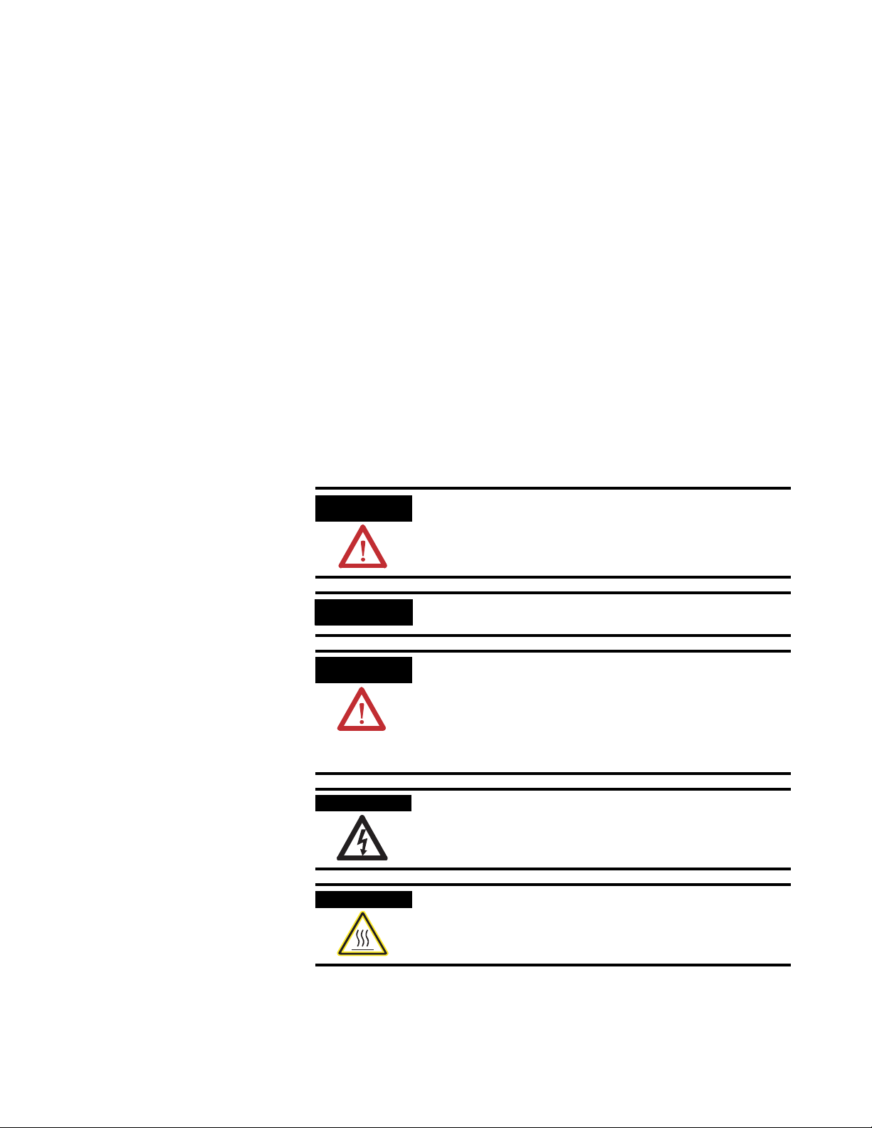
Throughout this manual we use notes to make you aware of safety considerations.
WARNING
IMPORTANT
ATTENTION
SHOCK HAZARD
BURN HAZARD
Identifies information about practices or circumstances
that can cause an explosion in a hazardous environment,
which may lead to personal injury or death, property
damage, or economic loss.
Identifies information that is critical for successful
application and understanding of the product.
Identifies information about practices or circumstances
that can lead to personal injury or death, property
damage, or economic loss. Attentions help you:
• identify a hazard
• avoid a hazard
• recognize the consequence
Labels may be located on or inside the drive to alert
people that dangerous voltage may be present.
Labels may be located on or inside the drive to alert
people that surfaces may be dangerous temperatures.
Page 3

Table of Contents
Preface
Introduction to the MobileView
SDK
Developing CE Drivers and
Applications
MobileView Terminals SDK
Using this Manual . . . . . . . . . . . . . . . . . . . . . . . . . . . Preface-3
Who Should Use This Manual . . . . . . . . . . . . . . . . . . Preface-3
Purpose of this Manual . . . . . . . . . . . . . . . . . . . . . . . Preface-3
Contents of this Manual. . . . . . . . . . . . . . . . . . . . . . . Preface-3
Manual Conventions . . . . . . . . . . . . . . . . . . . . . . . . . Preface-4
Allen-Bradley Support . . . . . . . . . . . . . . . . . . . . . . . . Preface-4
Local Product Support . . . . . . . . . . . . . . . . . . . . . . . . Preface-4
Technical Product Assistance . . . . . . . . . . . . . . . . . . . Preface-4
Chapter 1
Hardware Architecture . . . . . . . . . . . . . . . . . . . . . . . . . . . 1-1
Software Architecture . . . . . . . . . . . . . . . . . . . . . . . . . . . . 1-3
Chapter 2
General Considerations . . . . . . . . . . . . . . . . . . . . . . . . . . . 2-1
Setting Up the Development System . . . . . . . . . . . . . . . . . 2-3
Chapter 3
Overview . . . . . . . . . . . . . . . . . . . . . . . . . . . . . . . . . . . . . 3-1
SDK (Software Development Kit)
for MobileView Terminals
Chapter 4
Introduction . . . . . . . . . . . . . . . . . . . . . . . . . . . . . . . . . . . 4-1
Common Data Types. . . . . . . . . . . . . . . . . . . . . . . . . . . . . 4-1
Error Handling . . . . . . . . . . . . . . . . . . . . . . . . . . . . . . . . . 4-2
Start and Close Functions . . . . . . . . . . . . . . . . . . . . . . . . . 4-2
Configuration Functions . . . . . . . . . . . . . . . . . . . . . . . . . . 4-3
Functions for Reading the Configuration . . . . . . . . . . . . . . 4-5
Peripheral Functions . . . . . . . . . . . . . . . . . . . . . . . . . . . . . 4-8
Other Functions . . . . . . . . . . . . . . . . . . . . . . . . . . . . . . . . 4-14
Functions for Subscribing Events . . . . . . . . . . . . . . . . . . . . 4-18
Index
1 Publication 2727-UM004B-EN-P - February 2004
Page 4

Table of Contents 2
Publication 2727-UM004B-EN-P - February 2004
Page 5

Preface
Using this Manual
Who Should Use This Manual
Purpose of this Manual
Read this preface to familiarize yourself with the rest of the manual.
The preface covers the following topics:
• who should use this manual
• the purpose of the manual
• contents of the manual
• conventions used in this manual
• Allen-Bradley support
Use this manual if you are responsible for developing application
software to run on the MobileView Terminal.
This manual is a user guide for the Software Development Kit for the
MobileView Terminal. It gives an overview of the system and provides
detailed information about the contents of the software development
kit.
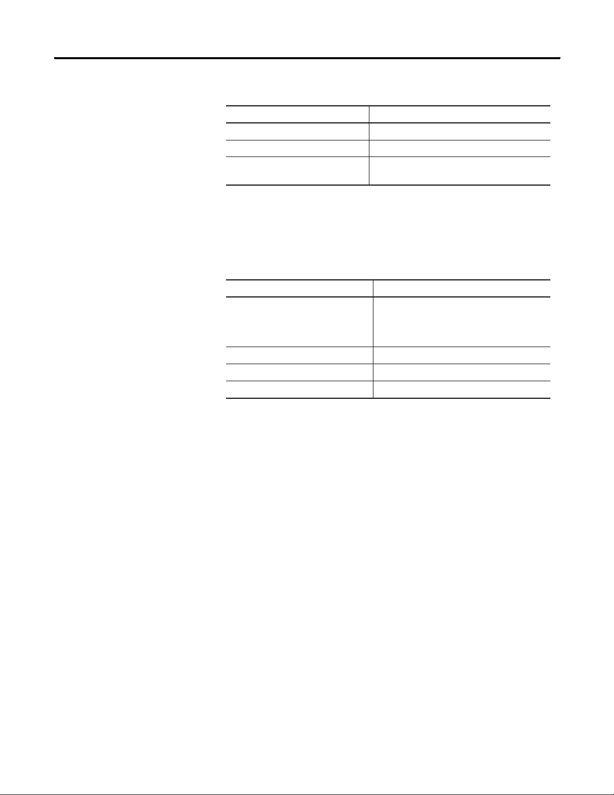
Contents of this Manual
Chapter Title Contents
Preface Describes the purpose, background,
and scope of this manual. Also
specifies the intended audience.
1 Introduction to the
MobileView SDK
2 Developing CE Drivers and
Applications
3 MobileView Terminals SDK Provides an overview of the
4 SDK (Software Development
Kit) for MobileView
Terminals
Provides an overview of the
MobileView Terminals and describes
the hardware and operating system
software.
Provides general guidelines for
programmers. Provides detailed
procedures for setting up the
development system and installing the
MobileView SDK.
MobileView SDK.
Provides detailed descriptions of the
MobileView functions.
1 Publication 2727-UM004B-EN-P - February 2004
Page 6

Preface 2
Manual Conventions
Allen-Bradley Support
Local Product Support
The following conventions are used throughout this manual:
• Bulleted lists such as this one provide information, not
procedural steps.
• Numbered lists provide sequential steps or hierarchical
information.
Allen-Bradley offers support services worldwide, with over 75
Sales/Support Offices, 512 authorized Distributors and 260 authorized
Systems Integrators located throughout the United States alone, plus
Allen-Bradley representatives in every major country in the world.
Contact your local Allen-Bradley representative for:
• sales and order support
• product technical training
• warranty support
• support service agreements
Technical Product Assistance
If you need to contact Allen-Bradley for technical assistance, please
review the information in the System Troubleshooting chapter first.
Then call your local Allen-Bradley representative or contact
Allen-Bradley technical support at (440) 646-5800.
For additional product information and a description of the technical
services available, visit the Rockwell Automation/Allen-Bradley
Internet site at http://www.ab.com.
Publication 2727-UM004B-EN-P - February 2004
Page 7
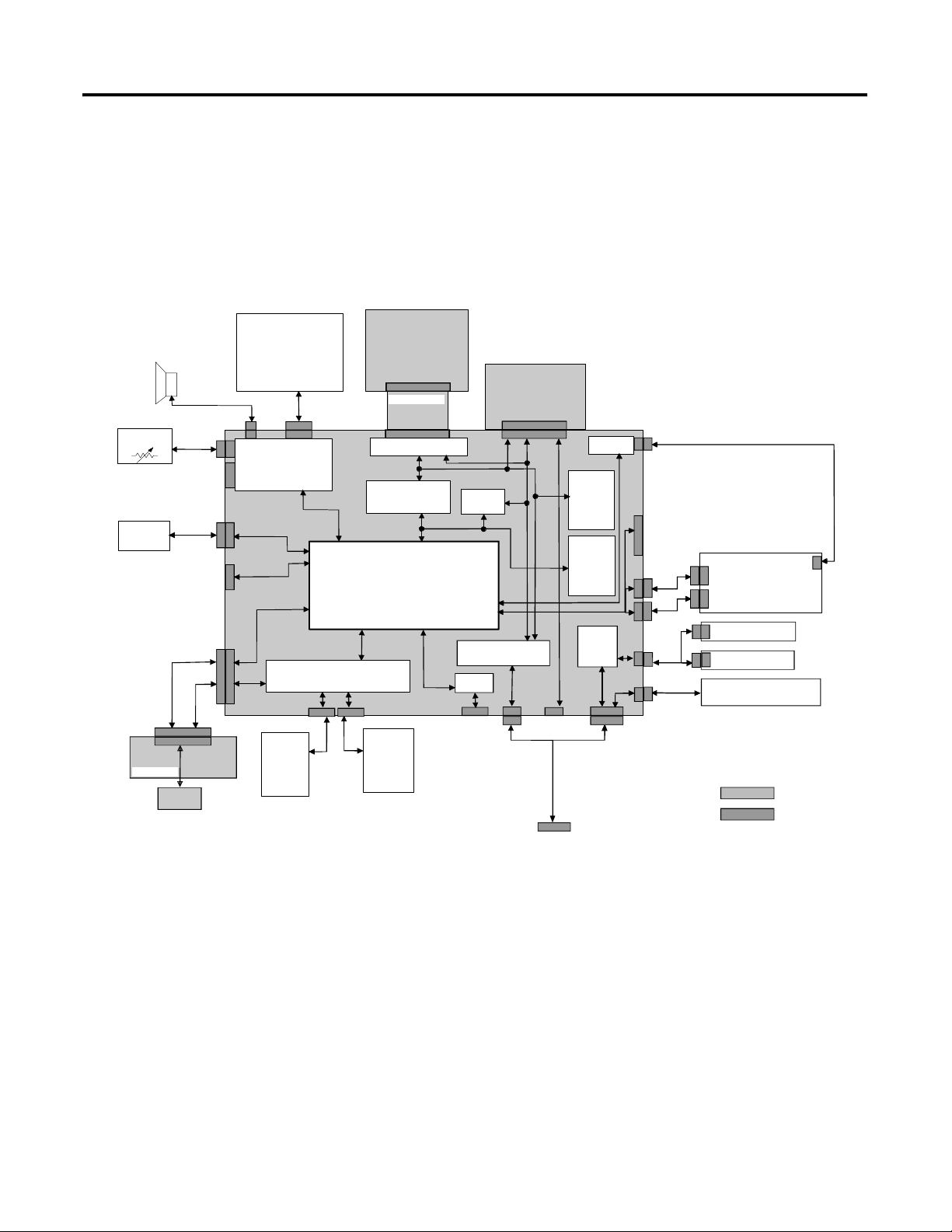
Hardware Architecture
TouchScreen
Analog resistive
Buzzer
Override
Potentiometer
Electronic
Handwheel
4-wire
Analog I/O
UCB 1200
Main PCB
Keyboard Electronic
Introduction to the MobileView SDK
MobileView PC2
GPIO
Serial por t 3
Serialport 2
PCMCIASlot
1x Type I-III
MobileView PC1
PCMCIA Buffer +
Power Management
Address & Data
Buffer
StrongARM 1110
206 MHz
Serial port 1
I²C
Ethernet Controller
SMSC 91C96
Serial Port
DEBUG
CommunicationPCB
e.g: RS422/RS485
CPLD
GPIO
GPIO
32MB
or 64MB
MT750 & G750
Block Diagram
backlight
inverter
FLASH
SDRAM
16MB
or 64MB
Electronic
Enabeling
device
Chapter
Color DSTN Display
VGA
640x480 pixels
Enabeling device left
Enab elingdev i c erigh t
Emergency Push Button
1
Keypad
rightside
Main Cable
PCB
Connector
MobileView SUB
IrD A
Push Buttons &
KeySwitches
Keypad
left side
CPU
The system processor is an Intel StrongARM SA-1110 Microprocessor,
a device optimized for meeting portable and embedded application
requirements. The SA-1110 incorporates a 32-bit StrongARM RISC
processor capable of running at up to 206 MHz. The SA-1110 has a
large instruction and data cache, memory-management unit (MMU),
and read/write buffers.
The SA-1110 memory bus interfaces to many device types including
synchronous DRAM (SDRAM), and SRAM-like variable latency I/O
1 Publication 2727-UM004B-EN-P - February 2004
Page 8

1-2 Introduction to the MobileView SDK
devices with a shared data ready signal. In addition, the SA-1110
provides system support logic, multiple serial communication
channels, a color/gray scale LCD controller, PCMCIA support, and
general-purpose I/O ports.
Memory Devices
Flash Device
There is a flash part (32 MB to 64 MB) that emulates a disk device.
The flash is partitioned to several logical storage areas. One partition
provides non-volatile storage for Windows CE operating system
image. Another partition is used to store the backup of the registry.
One partition is used for the boot code. The last partition supports a
FAT 16 (DOS compatible) file system, in which programs and data can
be stored.
DRAM
The MT/G750 models have two possible memory configurations:
16 MB DRAM/32 MB Flash and 64 MB DRAM/64 MB Flash.
The Operating System uses part of the RAM for a RAMDISK and the
other part for normal system memory. The RAMDISK portion is
known as the Object Store and provides specialized storage for the
Windows CE Registry and Windows CE system databases. The
Windows CE Control Panel System Properties tool has a slider control
that allows a user to determine how the RAM is allocated between
RAMDISK Storage and system memory. The slider control is factory set
for a 50/50 split. Application programs can control RAM allocation
with the Windows CE system call SetSystemMemoryDivision (see
Microsoft’s documentation of the CE API for details).
Interfaces
Real Time Clock
Publication 2727-UM004B-EN-P - February 2004
The SA-1110 uses on-chip oscillators and PLLs for clock generation.
The real-time clock and trim logic run off the 32.768 kHz crystal and
provide accuracy of 5 seconds/month. The real-time clock is not
battery backed and will reset when power is cycled.
Page 9

Introduction to the MobileView SDK 1-3
Keypad
The MobileView terminals have a numeric keypad and cursor control
keys. This includes 12 function keys.
Extended software support for the bezel keypad is provided with the
Windows CE operating system in the form of a keypad handler DLL.
The keypad handler intercepts and operates on codes produced by
the keypad driver before passing them to the application with current
focus.
Touch Screen
An integral, resistive analog touch screen with a serial controller
provides mouse-like operator input. The touch screen is factory
installed and associated with an integral display.
On-Board Ethernet
An on-board Ethernet controller provides 10BaseT, half-duplex
communication support. The data communication for these interfaces
takes place via the RJ45 Ethernet connector S4 in the cable entrance
area.
The following interface parameters are defined and cannot be
changed:
• 10 Mbaud
• TCP/IP protocol
The on-board Ethernet interface is configured under Windows CE as
follows:
Start - Settings - Control Panel - Network - Network Configurations
PCMCIA Slots
A PCMCIA slot connector supports 1 Type II PC Card. The PC Cards
can be memory or I/O devices.
Software Architecture
Windows CE OS
The MobileView is provided with Windows CE Version 4.x with the
latest service packs.
The system software includes the following components:
Publication 2727-UM004B-EN-P - February 2004
Page 10

1-4 Introduction to the MobileView SDK
• Hardware Initialization and Boot Loader, situated in the flash
• Windows CE Kernel with adaptations (Hardware Adaptation
Layer customized for the MobileView hardware, Built-in ISRs),
situated in the boot image stored in the operating system
partition of the Flash Storage
• Windows CE Default Registry, which is part of the boot image.
(A persistent registry, containing information relative to specific
configurations, is maintained in the file system and merged with
the default registry at boot.)
• Windows CE Modules and Device Drivers (File system
support,...), implemented as part of the boot image or as files
(dlls, exes, etc.) stored in the FAT16 partition of the Flash
Storage
• GUI Desktop Shell, implemented
• Control Panel and System Configuration/View Tools
Boot Sequence
The boot code in the Flash Storage gets control of the microprocessor
at power-on, initializes the hardware, performs power-on self-tests
(POST), and moves the compressed Windows CE operating system
image from the boot partition of the Flash Storage persistent storage
device into DRAM. Several seconds are required for the
decompression and copy operation. Finally, the boot loader jumps to
the start address of the Windows CE image and control passes to the
Windows CE operating system. Windows CE then loads drivers,
including the driver for the Flash Storage FAT16 file system (on the
“Flash Storage Space” partition), restores the registry, establishes the
video modes, and finally loads the start-up applications into memory
and runs them.
Load of Compressed Operating System
The boot code reads the compressed operating system image from the
Flash Storage operating system partition, decompresses it and loads it
into memory. (It loads the executable operating system code into
program memory and a default system registry into the RAMDISK
section of memory.) Control then passes to the operating system
image in memory.
Publication 2727-UM004B-EN-P - February 2004
“Cold Boot”
The operating system begins a “cold boot” by loading the driver for
the FAT file system on the Flash Storage.
Page 11

Introduction to the MobileView SDK 1-5
The operating system then attempts to find the primary persistent
registry file. If this file is not present, it attempts to find the backup
persistent registry file. If no persistent registry file is found, system
boot continues with the default registry already in memory.
If a persistent registry file is found, the system merges the default
operating system registry and the saved persistent registry; saved
persistent registry takes precedence.
“Warm Boot”
After the registry merge, a “warm boot” is begun. Control passes to the
operating system kernel, which can now use the registry image to
initialize various subsystems. The file system drivers, the graphical
subsystem drivers, serial, network, and other device drivers are loaded
and initialized.
The Windows CE Registry
The Windows CE Registry contains application and system
configuration data. The Control Panel provides the user interfaces for
managing the system settings that are configurable by the user.
Applications access the Registry via the Win32 API.
The default Registry resides in the operating system image in the flash
device. During runtime, the Registry is loaded into and resides in RAM
in the Object Store (RAMDISK).
When the system is powered-on, the registry is restored from Flash
Memory to DRAM during a “cold boot”.
The registry is only saved by manual operations. The user can execute
the "\windows\regflush.exe" program or call the FlushRegistry()
command from an application.
The operating system boot process is responsible for merging the
default operating system Registry keys with the keys from the
persistent Registry. If the same keys exist, preference is given to the
persistent registry file. A few default keys are exceptions to this rule
and are bypassed during the merge; e.g. the O/S version number is
acquired from the O/S image.
The process of merging default and persistent registry information
allows operating system upgrades to add new registry keys and values
and have these be used in addition to any saved registry state. Since
the saved registry information has precedence, users’ saved registry
Publication 2727-UM004B-EN-P - February 2004
Page 12

1-6 Introduction to the MobileView SDK
keys for control panel applets and other operating system items will
be maintained even in the case of operating system upgrades.
On the other hand, the priority given to persistent registry information
over default operating system registry information makes it possible
for applications or users to cause problems with operating system
startup by changing the wrong registry keys. When manipulating the
CE Registry applications, users should exercise the same degree of
caution that would be required in the case of a Windows 9x or NT
device.
IMPORTANT
Since some applications and drivers only read the
Registry at start-up, some registry changes made by
applications will have no effect until the terminal is
re-started.
Policies for When Registry Flushing Occurs
Control panel applets supplied with the operating system have been
customized to automatically flush the registry upon exiting the applet.
This allows users to change typical control panel settings such as
network, device name, screen saver, etc. and have these be flushed
without having to manually issue a registry flush to save these. Since
the flush occurs on applet exit as an optimization, users just need to
remember to close the applet after making changes for the automatic
flush to occur. Due to the inner workings of the applets, it is not
feasible to only flush on applet close if a value was changed, so a
flush occurs on applet close even if no registry values were actually
altered.
Other applications such as Internet Explorer, remote networking, and
any third-party packaged applications are not customizable in this
fashion and hence changes they make to the registry will not be
persistent until some other application flushes the registry. To address
this, two features of the operating system are present.
Publication 2727-UM004B-EN-P - February 2004
First, an executable regflush.exe supplied with the system may be
manually executed by a user at any time to flush the registry to
persistent storage; this application simply calls RegistryFlush().
Second, upon a controlled shutdown requested by an application
through the power/shutdown driver results in an automatic flush of
the registry after applications have signaled that their cleanup is
complete and before the hardware is actually shutdown or reset.
During an uncontrolled shutdown (i.e. hard-power down), the system
does not have enough time to flush the registry to persistent storage.
Page 13

Introduction to the MobileView SDK 1-7
Therefore, the registry must have been flushed by one of the means
described above or else changes to the registry since the last flush will
be lost. It is recommended that the controlled shutdown procedure be
used for shutdown even if other registry flushing by applications is in
place.
Local File Systems
The Windows CE operating system provides support for two separate
local file systems. A DOS compatible FAT16 file system is
implemented in a Flash Storage partition; accordingly, its files are
persistent. A RAM file system (RAMDISK or Object Store) is
implemented in that part of the system DRAM reserved for it. The files
in the RAM file system are not persistent.
The FAT16 and RAM file systems can be viewed and manipulated by
the Windows Explorer utility. Within the Windows Explorer, these
systems appear as parts of one larger system. That is, they appear as
directories under “My Computer”. The FAT16 file system appears as
“\Flash Storage”, while the RAM file system includes several
directories, including the most important, the “\Windows” directory,
where system binaries are stored.
Table 1.1 RAM File System
Directory Description
\Temp Not used
\My Documents Not used
\Program Files Contains links (shortcuts) to certain system
executables
\Program Files \Communications Contains links (shortcuts) to certain system
executables
\Windows Contains system executables (*.exe), dynamic
link libraries (*.dll), fonts (*.ttf), etc. making up
the Windows CE operating system
\Windows\Programs Contains links (shortcuts) to certain executables
in \Windows
\Windows\Programs\
Communication
\Windows\Desktop Contains links (shortcuts) that define the
\Windows\Favorites Not used
Contains links (shortcuts) to certain executables
in \Windows
contents of the Windows Desktop
Publication 2727-UM004B-EN-P - February 2004
Page 14
1-8 Introduction to the MobileView SDK
Table 1.1 RAM File System
Directory Description
\Windows\Fonts Not used
\Windows\Recent Not used
\Windows\Startup Contains links (shortcuts) to certain executables
in \Windows
The FAT16 (persistent) file system, “\Flash Storage”, is organized as
follows:
Table 1.2 FAT16 File System
Directory Description
\Flash Storage Contains backups of the system registry and
the system exceptions log. Applications should
be stored here or in subdirectories created
here.
\Flash Storage\Temp
\Flash Storage\Windows\Desktop Contains links to certain system executables
\Flash Storage\Windows\ Programs Contains links to certain system executables
Input Device Handlers
Touch Screen
The display is equipped with a high resolution resistive touch screen.
The Windows CE operating system incorporates a driver for the touch
screen.
A user interface is provided to enable touch screen configuration and
calibration. Touch screen calibration values are stored in the registry.
Keyboards
Support is present in the operating system for the bezel keypad.
Publication 2727-UM004B-EN-P - February 2004
Page 15

Introduction to the MobileView SDK 1-9
PCMCIA
New or upgraded components of application programs and the
operating system can be copied from the PCMCIA memory card to
Storage Card memory to replace and upgrade the existing
components.
In the Windows Explorer, the PCMCIA Memory Card will show up as
an icon named “\Storage Card”.
Application Run Time Environment
Path
The notion of a path to executable files is much the same as with any
other Windows or DOS system. However, unlike other systems, which
refer to an environment variable for path settings, Windows CE
utilizes a registry entry. Thus, the path can be set only by editing the
value of the registry key \HKLM\Loader\SystemPath. Note the use of
spaces to separate items in the path list, as in the following example:
“\Storage Card\bin\ \Storage Card\ \ Storage Card\bin\ \Storage
Card\ ...”
Launching Applications At Start-Up
The Windows CE Registry entries at key HKLM\init determine the
programs that are started during system initialization, and the order in
which they are started. The Windows CE Platform Builder
development tool (not part of the Embedded Visual C 4.x) is used to
establish these Registry entries.
Table 1.3 MobileView Terminals Launch Order
Sequence Program or File Description
Launch10 shell.exe Start the shell
Launch20 device.exe Load and start the device drivers
Launch30 gwes.exe Start graphics and events subsystems
Depend30 14 00 When device.exe signals complete
Launch50 explorer.exe Start Windows Explorer
Publication 2727-UM004B-EN-P - February 2004
Page 16

1-10 Introduction to the MobileView SDK
Table 1.3 MobileView Terminals Launch Order
Sequence Program or File Description
Depend50 14 00 IE 00 When device.exe and gwes.exe complete
startup
Launch70 kukinit.exe Used for touch calibration
Depend70 14 00 IE 00 When device.exe and gwes.exe complete
startup
Launch90 provides a launch point at startup for an OEM that assures
that the device drivers, TCP/IP, registry and GUI functions are up and
running.
Explorer is launched during initialization because it handles the GUI
shell, taskbar, running items in \windows\startup, etc. Unlike other
executable files, Windows Explorer does not properly signal that it
has completed startup, so dependencies should not be placed directly
on explorer.exe. Consequently, the start menu, taskbar, etc. may still
be drawing when oemstartup.exe is called.
Although there is a \windows\startup folder in the file system, the
placement of a shortcut in this folder in order to start the associated
application automatically at system startup is not recommended. The
folder \windows\startup is RAM based, and its contents will not
persist from one operating session to the next.
The solution is to place shortcuts in \Flash Storage\Windows or in a
directory under it. In a normal system initialization sequence,
everything in \Flash Storage\Windows\ (in the persistent file system),
including subdirectories and their contents, is copied to \Windows (in
the RAM filesystem) following the startup of gwes.exe.
Process Priorities
All executable files start in user mode. Any application can change to
kernel mode or back with the Windows CE SetKMode() call. The only
known exception is nk.exe, which is started first and doesn't follow
the same rules.
System Shutdown
Publication 2727-UM004B-EN-P - February 2004
The system supports a soft reset and provides a shut-down indicator
in non-volatile memory.
Page 17

Chapter
2
Developing CE Drivers and Applications
General Considerations
There are two general considerations for developing drivers and
applications for the MobileView:
• Distributing and installing applications
• Persistence considerations
Application Distribution and Installation
Application programs consist of EXE and DLL files that will reside in
the FAT partition of the Flash Storage. They will be installed much like
applications for Windows desktop operating systems.
Typically, a CE application will be distributed as a package containing
the run-time components, in compressed form, and an executable
“installation script” that manages the installation process. When the
installation script (typically “Setup.exe”) is run, the run-time
components will be decompressed and moved to their assigned
folder(s), desktop icons and start menu entries will be created, and
the system registry will be edited to register the application’s
components and associated parameters. Finally, an uninstall script
will be created and saved.
The InstallShield tool from InstallShield Corporation is recommended
for packaging applications for distribution. This tool alleviates some of
the difficulties associated with the development of installation scripts
and imposes a familiar “look and feel” on the installation process.
The application developer should give some thought to the means to
be used for distributing the installation script. Generally, there are two
means available: CDROM and the internet.
Installing the Application
Once the user has obtained an installation script by one of these
methods and the script resides on the user’s local desktop PC, he or
she may use any of three methods to install the application on the
MobileView.
Perform a remote installation by running the script on a PC host that is
connected to the MobileView using Data Exchange.
1 Publication 2727-UM004B-EN-P - February 2004
Page 18

2-2 Developing CE Drivers and Applications
Copy the script from a PC host using Data Exchange or from a
PCMCIA ATA memory card to the “\Flash Storage\” folder on the
MobileView and run the script on the MobileView.
Run the script directly from a PCMCIA ATA memory card on the
MobileView.
Remote Installations
The install package can be quite large and the decompression process
can consume high levels of memory, so remote installation is an
attractive option. Data Exchange, using CeAppMgr.exe on the host PC
and WCEload.exe on the MobileView, supports remote installation.
Application Upgrades
The application developer should make appropriate provisions for
issuing application upgrades from the beginning, adopting good
practice for source version control, bug reporting, etc. When
upgrades are required, typically with the desire to add new features or
to implement bug fixes, decisions will have to be made relating to the
notification of users and the distribution of the upgrades.
Considerations for the distribution and installation of application
upgrades are exactly the same as those discussed above for initial
distribution and installation.
Persistence Considerations
Installation of a new application program typically adds a new icon to
the Windows CE Desktop and sometimes a new entry in the Start
Menu, in order to enable the user to launch the new program or to
launch it automatically. Shortcuts in the folder “\Windows\Desktop”
create the Icons on the desktop. Shortcuts and subfolders in the folder
“\Windows\Programs” form the Start Menu. A shortcut in the folder
“\Windows\Startup” will automatically launch a program at startup. A
control panel applet that was added by an application has a file
extension *.CPL and resides in the folder “\Windows.
All this appears very Windows-like and ordinary until one considers
that the “\Windows” folder is effectively a RAM disk that is recreated
when cold-started; i.e. it is not persistent. When the operating system
boots it creates a new file system including “\Windows” and that
effectively removes all traces of the end-user applications that once
existed. With that in mind, special considerations are necessary for
applications on the MobileView and all similar embedded devices
since the Icons, the Start Menu, and application-provided Control
Panel Applets must be re-created at startup.
Publication 2727-UM004B-EN-P - February 2004
Page 19

Developing CE Drivers and Applications 2-3
The solution is to place shortcuts in \Flash Storage\Windows or in a
directory under it. In a normal system initialization sequence,
everything in \Flash Storage\Windows\ (in the persistent file system),
including subdirectories and their contents, is copied to \Windows (in
the RAM filesystem) following the startup of gwes.exe. (For further
information see “Launching Applications At Start-Up” above.)
Setting Up the Development System
Typically, development will take place on an x86 machine running a
Microsoft Win32 operating system and Microsoft cross development
tools. The development system will be connected to the target
MobileView by Ethernet or serial link, and StrongARM binary files
generated on the development system will be downloaded to the
target for testing and debugging.
While for the most part the Microsoft development tools will run on
Windows 95, Windows 98, Windows 2000 and Windows XP, certain
special functions, like emulation of the target platform on the x86
host, are available to the developer only with Windows NT 4.0.
Application development can be carried out using either C/C++ or the
.net framework. Note that the C/C++ development system normally
produces StrongARM binaries that are directly executable on the
MobileView. Device driver developers should plan to use C/C++.
Setting Up the Host Machine for C/C++ Development
First, Microsoft Windows CE Services (Active Sync) must be installed
on the host system. This package provides utilities needed to
download applications to the MobileView and to support a number of
remote development tools. Windows CE Services is provided on
CDROM with the MobileView. The MobileView Guard Terminal
(2727-UM002) and MobileView Machine Terminal (2727-UM003)
User’s Manuals contain detailed information about connections.
Next, the following Microsoft development tools must be installed on
the host system, in the order given:
• Embedded Visual C++ 4.0
• Platform SDK for H/PC – StrongARM (from Microsoft Embedded
Visual Tools 4.x)
Publication 2727-UM004B-EN-P - February 2004
Page 20

2-4 Developing CE Drivers and Applications
TIP
Microsoft Embedded Visual Tools 4.x is available
without charge, except for a nominal shipping and
handling charge. Accordingly, it is an economical
tool for developers of new CE only applications.
Device driver developers should consider also installing the Microsoft
Windows CE Platform Builder, which contains support for kernel level
CE development that is not found in the other toolkits. However,
Platform builder is not necessary for most driver development work.
Details of the installation procedures are beyond the scope of this
manual. Please follow the instructions provided by Microsoft.
Finally, the MobileView SDK should be installed. (See detailed
instructions below.)
Setting Up the Development System
1. First, install Microsoft ActiveSync on the host system. This
utility is needed to download applications to the MobileView
terminal and supports several helpful remote development tools.
ActiveSync 3.7 is available for download from Microsoft at
http://www.microsoft.com/downloads/
Terminal User Manual (2727-UM002) and the MobileView
Machine Terminal User Manual (2727-UM003) both contain
detailed information about connections.
. The MobileView Guard
Publication 2727-UM004B-EN-P - February 2004
2. Next, install Microsoft
eMbedded Visual C++ 4.x and Service
Pack 1. This is the development environment for building
Windows CE .NET applications using C/C++, the Win 32 API
and MFC. eMbedded Visual C++ 4.0 is available for download
from Microsoft at http://www.microsoft.com/downloads/
or can
be purchased on CD from the Microsoft Evaluation and
Resource Center at http://microsoft.order-5.com/trialstore/
.
3. Install the MobileView CE Software Development Kit (SDK) that
is distributed on the CD, Part Number 77190-914-51. Load the
CD, browse to the Software Development Kit folder and then
install the package named "MT750_SDK_V2.00.008.msi".
Details of the installation procedures are beyond the scope of this
manual. Please follow the instructions and readme files that are
provided with the respective products and CDs.
Page 21

Developing CE Drivers and Applications 2-5
Microsoft Embedded Visual C++ 4.x is available without charge,
except for a nominal shipping and handling charge. Accordingly, it is
a highly economical tool for developers of CE application programs.
Device driver developers should also consider installing Microsoft
Windows CE Platform Builder 4.1, which has extensive support for
kernel level CE development that is not found in the other toolkits.
However, Platform Builder is not necessary for most driver
development work.
Publication 2727-UM004B-EN-P - February 2004
Page 22

2-6 Developing CE Drivers and Applications
Publication 2727-UM004B-EN-P - February 2004
Page 23

MobileView Terminals SDK
Chapter
3
Overview
The MobileView Terminals SDK provides developers with access to an
extensive set of functions that are specific to the MobileView
Terminals hardware and constitute extensions of the standard
Windows CE API. These functions, like the standard Windows CE
functions, are implemented in the C language and can be called
directly from C or C++ programs.
A file called “ketopapi.bas” is included in the MobileView Terminals
SDK. This file includes Basic declarations for all the constants, data
structures and functions associated with the MobileView SDK C
language libraries. Basic programmers can copy declarations from this
file into their programs as needed, just as they can copy the
declarations for the standard CE functions from a Microsoft provided
file called “winceapi.txt”.
C/C++ language developers should note that the headers included in
the MobileView SDK contain conditionals that allow them to be
included in C and C++ modules without modification. A C++ program
should include a #define __cplusplus directive prior to an #include
<sdk_header> directive, or else the __cplusplus macro should be
defined on the compiler command line.
On the other hand, users of this IDE who wish to write in standard C
should keep in mind that this default situation will require all standard
C modules to be conditionally bracketed in the same way that the
headers in the SDK are bracketed. For example:
#ifdef __cplusplus
extern “C” {
#endif
/* C code goes here */
#ifdef __cplusplus
}
#endif
1 Publication 2727-UM004B-EN-P - February 2004
Page 24

3-2 MobileView Terminals SDK
Publication 2727-UM004B-EN-P - February 2004
Page 25

Chapter
SDK (Software Development Kit) for MobileView Terminals
4
Introduction
The SDK (Software Development Kit) resides in a single dynamic link
library (DLL). All functions described in this document are exported
from this DLL. This document includes information on:
• Common Data Types
• Error Handling
• Start and Close Functions
• Configuration Functions
• Functions for Reading the Configuration
• Peripheral Functions
• Keypad Functions
• Other Functions
• Functions for Subscribing Events
Visual Basic is no longer supported in Windows CE 4.x. The .NET
frame work has superseded Visual Basic. For details on porting
Visual Basic applications, please consult the Microsoft website:
http://www.microsoft.com
Common Data Types
1 Publication 2727-UM004B-EN-P - February 2004
The SDK uses common data types to communicate with the
MobileView terminal. This table below provides a description of these
data types. For further information, see TpuHwDataTypes.h.
Table 4.1
INT8 Signed 8 bit integer variable
UINT8 Unsigned 8 bit integer variable
BacklightStat Enum, displays the backlight status.
JoystickPos Struct, for joystick data.
Status Struct Describes the startup state of the device.
EventMsg Enum, describes the event message received.
EventMsgDomains Enum, describes the events a handler has been
subscribed to.
EventCallback Function pointer to callback function.
Page 26

4-2 SDK (Software Development Kit) for MobileView Terminals
Error Handling
Rules
Functions expecting an input parameter verify that the parameter is
inside the range and has the correct data type.
• If a parameter is located outside the range the function returns
INVALID_ARG_RANGE.
• Functions expecting a pointer for output data as a parameter
verify that the pointer is valid (for example, the pointer must not
be NULL). If the pointer is invalid, the function returns
IN VAL ID_ ARG _I NVAL ID_ PT R.
• Functions with a string as a parameter verify that the pointer to
the string is valid. If the pointer is invalid, the function returns
INVALID_ARG_INVALID_STR_PTR.
Error Codes
Table 4.2
Start and Close Functions
SUCCESS 0
OK 0
FAIL 1
INVALID_ARG_RANGE 2
INVALID_ARG_PTR 3
INVALID_ARG_STR_PTR 4
INVALID_ARG_UNKNWN_COOKIE 5
INVALID_ARG_UNKNWN_DOMAINS 6
INVALID_NOT_CALIBRATED 7
This section describes functions that are required to start and close the
SDK dll.
Publication 2727-UM004B-EN-P - February 2004
Page 27

SDK (Software Development Kit) for MobileView Terminals 4-3
KtpAPIInit
Table 4.3
Declaration:
Visual C: UINT8 KtpAPIInit(void);
Visual Basic: KtpAPIInit() As Byte;
Description: This method initializes the MobileView SDK.
KtpAPIDeinit
Table 4.4
Configuration Functions
Declaration:
Visual C: void KtpAPIDeinit(void);
Visual Basic: KtpAPIDeinit()
Description: This method cancels all initialization of the MobileView SDK.
This section describes functions that are required to configure the
MobileView terminal. All functions return one of the error codes listed
in the Error Handling section.
KtpSetBrightness
Table 4.5
Declaration:
Visual C: UINT8 KtpSetBrightness(/*[in]*/UINT8 u8_Brightness);
Visual Basic: KtpSetBrightness(ByVal brightness As Byte) As Byte
Description: This method sets the brightness of the LC display on the device.
Arguments 0-7, 0 = min, 7 = max
Publication 2727-UM004B-EN-P - February 2004
Page 28

4-4 SDK (Software Development Kit) for MobileView Terminals
KtpSetContrast
Table 4.6
Declaration:
Visual C: UINT8 KtpSetContrast(/*[in]*/UINT8 u8_Contrast);
Visual Basic: KtpSetContrast(ByVal contrast As Byte) As Byte
Description: This method sets the contrast of the LC display on the device.
Arguments 0 to 31, 0 = min, 31 = max
KtpSwitchBacklight
(MobileView: 0 to 63,
0 = min, 63 = max)
Table 4.7
Declaration:
Visual C: UINT8 KtpSwitchBacklight(/*[in]*/BacklightStat backLight);
Visual Basic: KtpSwitchBacklight(ByVal backlight As Integer) As Byte
Description: Turns on/off the backlight of the LC display on the device.
Arguments BACKLIGHT_ON, BACKLIGHT_OFF
KtpScreenSaverTimeOutMin
Table 4.8
Declaration:
Visual C: UINT8 SetScreenSaverTimeOutMin(/*[in]*/UINT8 u8_ScreenSaverTO);
Visual Basic: KtpSetScreenSaverTimeOutMin(ByVal sreenSaverTO As Byte) As Byte
Description: Sets the timeout value of the screensaver in minutes.
Arguments 0-255, 0 = off, 255 = max
Publication 2727-UM004B-EN-P - February 2004
Page 29

SDK (Software Development Kit) for MobileView Terminals 4-5
KtpSetScreenSaverTimeOutSec
Table 4.9
Declaration:
Visual C: UINT8 SetScreenSaverTimeOutMin(/*[in]*/UINT16
u16_ScreenSaverTO);
Visual Basic: KtpSetScreenSaverTimeOutSec(ByVal sreenSaverTO As Integer) As
Byte
Description: Sets the timeout value of the screensaver in seconds.
Arguments 0-65535, 0 = off, 65535 = max
KtpSetBuzzerVolume
Functions for Reading the Configuration
Table 4.10
Declaration:
Visual C: UINT8 KtpSetBuzzerVolume(/*[in]*/UINT8 u8_Volume);
Visual Basic: KtpSetBuzzerVolume(ByVal volume As Byte) As Byte
Description: Sets the volume of the buzzer.
Arguments 0-16, 0 = off, 16 = max
Functions that read a configuration return the current value of the
configuration parameters. None of the functions require a parameter.
These functions do not check for errors since the return value of the
function is the value of the configuration parameter.
KtpGetBrightness
Table 4.11
Declaration:
Visual C: UINT8 KtpGetBrightness(void);
Visual Basic: KtpGetBrightness() As Byte
Description: Gets the current brightness value of the LC display.
Publication 2727-UM004B-EN-P - February 2004
Page 30

4-6 SDK (Software Development Kit) for MobileView Terminals
KtpGetContrast
Table 4.12
Declaration:
Visual C: UINT8 KtpGetContrast(void);
Visual Basic: KtpGetContrast() As Byte
Description: Gets the current contrast value of the LC display.
KtpGetBacklight
Table 4.13
Declaration:
Visual C: TKtpBacklightStat KtpGetBacklight(void);
Visual Basic: KtpGetBacklight() As Integer
Description: Gets the current status of the background lighting.
Publication 2727-UM004B-EN-P - February 2004
Page 31

SDK (Software Development Kit) for MobileView Terminals 4-7
KtpGetScreenSaverTimeoutMin
Table 4.14
Declaration:
Visual C: UINT8 GetScreenSaverTimeOutMin(void);
Visual Basic: KtpGetScreenSaverTimeOutMin() As Byte
Description: Gets the current timeout value of the screensaver in minutes.
KtpGetScreenSaverTimeoutSec
Table 4.15
Declaration:
Visual C: UINT8 GetScreenSaverTimeOutSec(void);
Visual Basic: KtpGetScreenSaverTimeOutSec() As Integer
Description: Gets the current timeout value of the screensaver in seconds.
KtpGetBuzzerVolume
Table 4.16
Declaration:
Visual C: UINT8 KtpGetBuzzerVolume(void);
Visual Basic: KtpGetBuzzerVoume() As Byte
Description: Gets the current volume value of the buzzer.
Publication 2727-UM004B-EN-P - February 2004
Page 32

4-8 SDK (Software Development Kit) for MobileView Terminals
Peripheral Functions
KtpJoystickIsInstalled
Table 4.17
Declaration:
Visual C: UINT8 KtpJoystickIsInstalled(void);
Visual Basic: KtpJoystickIsInstalled() As Byte
Description: Returns the number of joystick axes. If no joystick is installed on
the device, 0 will be returned.
KtpWheelIsInstalled
Table 4.18
Declaration:
Visual C: UINT8 KtpWheelIsInstalled(void);
Visual Basic: KtpWheelIsInstalled() As Byte
Description: Returns 1 if a wheel is installed on the device, otherwise 0.
KtpPotilsInstalled
Table 4.19
Declaration:
Visual C: UINT8 KtpPotiIsInstalled(void);
Visual Basic: KtpPotiIsInstalled() As Byte
Description: Returns 1 if an override potentiometer is installed on the device,
otherwise 0.
Publication 2727-UM004B-EN-P - February 2004
Page 33

SDK (Software Development Kit) for MobileView Terminals 4-9
KtpGetJoystickPos
Table 4.20
Declaration:
Visual C: UINT8 KtpGetJoystickPos (/*[out]*/TKtpJoystickPos *p_jPos);
Description: Gets the current joystick position.
Arguments TKtpJoystickPos structure. Each component in the structure may
only range between -15 and 15.
Remarks Calling this function is only allowed if a joystick is installed on
the device. If no joystick is installed the values of the components
are undefined.
Publication 2727-UM004B-EN-P - February 2004
Page 34

4-10 SDK (Software Development Kit) for MobileView Terminals
KtpGetJoystickPosEx
Table 4.21
Declaration:
Visual C UINT8 KtpGetJoystickPosEx(/*[out]*/int *posX, int *posY, int *posZ);
Visual Basic: KtpGetJoystickPosEx(ByRef posX As Integer, ByRef
Description: Gets the current joystick position.
Arguments Each component in the structure may only range between -15 and 15.
Remarks Calling this function is only allowed if a joystick is installed on the
posY As Integer, ByRef posZ As Integer) As Byte
device. If no joystick is installed the values of the components are
undefined.
KtpGetJoystickPosRaw
Table 4.22
Declaration:
Visual C: UINT8 KtpGetJoystickPosRaw (/*[out]*/TktpJoystickPosRaw*p_jPos);
Visual Basic: KtpGetJoystickPosEx(ByRef posX As Integer, ByRef
posY As Integer, ByRef posZ As Integer) As Byte
Description: Gets the actual raw data of the joystick.
Remarks Calling this function is only allowed if a joystick is installed on the
device. If no joystick is installed the values of the components are
undefined.
KtpGetJoystickPosRawEx
Table 4.23
Publication 2727-UM004B-EN-P - February 2004
Declaration:
Visual C: UINT8 KtpGetJoystickPosEx(/*[out]*/UINT16 *posX,
UINT16 *posY, UINT16 *posZ);
Page 35

SDK (Software Development Kit) for MobileView Terminals 4-11
Table 4.23
Visual Basic: KtpGetJoystickPosEx(ByRef posX As Integer, ByRef
posY As Integer, ByRef posZ As Integer) As Byte
Description: Gets the actual raw data of the joystick.
Remarks Calling this function is only allowed if a joystick is installed on the
device. If no joystick is installed the values of the components are
undefined.
KtpGetJoystickCalibData
Table 4.24
Declaration:
Visual C: UINT8 KtpSetJoystickCalibData(/*in*/TKtpJoystickChannel ch
UINT16 rawMin, UINT16 rawCenter, UINT16 rawMax, UINT16
calibRange);
Visual Basic: KtpSetJoystickCalibData(ByVal joystickChannel As Integer,
ByVal rawMin As Integer, ByVal rawCenter As Integer,
ByVal rawMax As Integer, ByVal calibRange As Integer);
Description: Calibrates the axis of the joystick.
Arguments: TktpJoystickChannel ch: channel to be calibrated.
UINT16 rawMin: value for smallest raw value
UINT16 ramCenter: average value for raw data
UINT16 rawMax: maximum value of raw data
UINT16 calibRange: maximum range of joystick
Remarks This function may only be called if a joystick is installed on the device. If
no joystick is installed, the value of the components are undefined.
KtpGetOverridePoti
Table 4.25
Declaration:
Visual C: UINT8 KtpGetOverridePoti(/*out*/UINT8 *p_pos);
Visual Basic: KtpGetOverridePoti(ByRef pos As Byte)
Publication 2727-UM004B-EN-P - February 2004
Page 36

4-12 SDK (Software Development Kit) for MobileView Terminals
Table 4.25
Description: Gets the current value of the override potentiometers.
Arguments: Pointer to the variable containing the current value of the
Remarks This function may only be called if a override potentiometer is
KtpGetOverridePotiRaw
Table 4.26
Declaration:
Visual C: UINT8 KtpGetOverridePotiRaw(/*out*/UINT16 *p_pos);
override potentiometer.
installed on the device. If no override potentiometer is installed,
the value of the components are undefined.
Visual Basic: KtpGetOverridePotiRaw(ByRef pos As Byte) As Byte;
Description: Gets the uncalibrated value from the override potentiometer.
Arguments: Pointer to the variable containing the current value of the
override potentiometer.
Remarks This function may only be called if a override potentiometer is
installed on the device. If no override potentiometer is installed,
the value of the components are undefined.
KtpGetEnablingDevice
Table 4.27
Declaration:
Visual C: UINT8 KtpGetEnablingDevice(/*in*/
TKtpEnablingDeviceCircuit circuit);
Visual Basic: KtpGetEnablingDevice(ByRef deviceCircuit As Integer)
As Byte;
Publication 2727-UM004B-EN-P - February 2004
Description: Circuit is the value of the enabling switch to be read.
Arguments: Returns the current value of the enabling switch transferred in
the circuit
Page 37

SDK (Software Development Kit) for MobileView Terminals 4-13
KtpSetPotiCalibData
Table 4.28
Declaration:
Visual C: UINT8 KtpSetPotiCalibData(/*in*/ UINT16 rawMin,
UINT16 rawMax, UINT16 calibRange);
Visual Basic: KtpSetPotiCalibData(ByVal rawMin As Integer,
ByVal rawMax As Integer, ByVal calibRange As
Arguments: UINT16 rawMin: value for smallest raw value
UINT16 rawMax: maximum raw value
UINT16 calibRange: maximum range of overridepoti
Description: Calibration of override potentiometer.
This function may only be called if an override potentiometer is
installed on the device. If no override potentiometer is installed,
the value of the components are undefined.
KtpGetWheelValue
Table 4.29
Declaration:
Visual C: UINT8 KtpGetWheelValue(/*out*/UINT16 *p_val);
Visual Basic: KGetWheelValue(ByRef val As Integer) As Byte
Description: Gets the actual value of the handwheel.
Arguments: Pointer to the variable containing the current value of the
handwheel.
Remarks: This function may only be called if a handwheel is installed on
the device. If no handwheel is installed, the value of the
components are undefined.
Publication 2727-UM004B-EN-P - February 2004
Page 38

4-14 SDK (Software Development Kit) for MobileView Terminals
KtpSetWheelValue
Table 4.30
Declaration:
Visual C: UINT8 KtpSetWheelValue(/*in*/UINT16 val);
Visual Basic: KtpSetWheelValue(ByVal val As Integer) As Byte
Description: Sets the current position of the handwheel to the value
Arguments: val is the value the handwheel should be set to.
Remarks: This function may only be called if a handwheel is installed on
transferred in val.
the device. If no handwheel is installed, the value of the
components are undefined.
Other Functions
This section covers other functions that perform various actions by the
MobileView terminal.
KtpGetStatus
Table 4.31
Declaration:
Visual C: UINT8 KtpGetStatus(/*[out]*/Status *p_tpuStatus);
Visual Basic: KtpGetStatus(ByRef ktpStatus As Byte) As Byte
Description: Gets the start-up state of the handheld terminal.
Arguments: Status *p_tpuStatus, pointer to memory area that will receive a
copy of the status structure.
Publication 2727-UM004B-EN-P - February 2004
Page 39

SDK (Software Development Kit) for MobileView Terminals 4-15
KtpWriteToFlash
Table 4.32
Declaration:
Visual C: UINT8 WriteToFlash(void);
Visual Basic: KtpGetWriteToFlash() As Byte
Description: Writes the registry of the device to the flash.
KtpReset
Table 4.33
Declaration:
Visual C: UINT8 KtpReset(void);
Visual Basic: KtpReset () As Byte
Description: Restarts the device new.
KtpGetVersionString
Table 4.34
Declaration:
Visual C: UINT8 KtpGetVersionString(/*out*/TCHAR
*wszVersionString, unsigned int bufferLen);
Visual Basic: KtpGetVersionString (ByRef versionString As String,
ByVal buffSize As Integer) As Byte
Description: Returns the state of the KETOP during start-up.
Arguments: TCHAR *wszVersionString: pointer to buffer for the versions
string unsigned int bufferLen: length of transferred buffer.
Publication 2727-UM004B-EN-P - February 2004
Page 40

4-16 SDK (Software Development Kit) for MobileView Terminals
KtpGetEEPromData
Table 4.35
Declaration:
Visual C: UINT8 KtpGetEEPromData(/*out*/TEEPromData *data);
Visual Basic: not implemented.
Description: Reads data from the EEProm.
Arguments: TEEPromData data: data structure for the data contained in the
KtpWriteByteToEEProm
EEProm
Table 4.36
Declaration:
Visual C: UINT8 KtpWriteByteToEEProm (/*in*/UINT16 addr, UINT8 data);
Visual
Basic:
Description: Writes a byte to the EEProm location transferred in addr.
Arguments: UINT16 addr: address of memory location
KtpWriteByteToEEProm (ByVal addr As Integer, ByVal data As Byte) As
Byte;
UINT8 data: data for saving
KtpReadByteToEEProm
Table 4.37
Declaration:
Visual C: UINT8 KtpReadByteToEEProm (/*in*/UINT16 addr, /*out*/ UINT8 *pData);
Visual
Basic:
Description: Reads a byte from the EEProm location transferred in addr.
KtpWriteByteToEEProm (ByVal addr As Integer, ByRef pData as Byte) As
Byte;
Publication 2727-UM004B-EN-P - February 2004
Arguments: UINT16 addr: address of memory location
UINT8 *pData: data from the EEProm
Page 41

SDK (Software Development Kit) for MobileView Terminals 4-17
KtpLaunchTouchScreenCalibApp
Table 4.38
Declaration:
Visual C: UINT8 KtpLaunchTouchScreenCalibApp (void);
Visual Basic: KtpLaunchTouchScreenCalibApp () As Byte;
Description: Starts the touch-screen calibration tool.
KtpGetTemperature
Table 4.39
Declaration:
Visual C: UINT8 KtpGetTemperature (void);
Visual Basic: KtpGetTemperature () As Integer;
Description: Returns the current temperature of the MobileView.
KtpPlaySound
Table 4.40
Declaration:
Visual C: UINT8 KtpPlaySound (/*in*/ UINT16 soundNr);
Visual Basic: KtpPlaySound (ByVal soundNr As Integer) As Byte;
Description: Plays the system sound in soundNr.
Arguments: UINT16 soundNr: number of system sound.
Publication 2727-UM004B-EN-P - February 2004
Page 42

4-18 SDK (Software Development Kit) for MobileView Terminals
KtpDoBeep
Table 4.41
Declaration:
Visual C: UINT8 KtpDoBeep (/*in*/ UINT8 beepTime10ms);
Visual Basic: KtpDoBeep (ByVal beepTime10ms As Byte) As Byte;
Description: Is active for beepTime10ms * 10 ms
Arguments: UINT8 beeptime10ms: duration of beeps in n* 10ms
KtpGetVariantData
Functions for Subscribing Events
Table 4.42
Declaration:
Visual C: UINT8 KtpGetVariantData (/*out*/ TKtpVariantData *data);
Description: Reads the device configuration from the EEProm.
Arguments: TKtpVariantData data: data structure for VariantData.
The functions in this section subscribe/unsubscribe callback functions
for different events. Events can be the joystick, override
potentiometer, handwheel and keypad.
KtpInstallWheelEventCallback
Table 4.43
Declaration:
Visual C: UINT8 KtpInstallWheelEventCallback
(/*in*/TktpWheelEventCallback pWheelProc, int
Publication 2727-UM004B-EN-P - February 2004
Page 43

SDK (Software Development Kit) for MobileView Terminals 4-19
Table 4.43
Visual Basic: function not implemented
Description: Subscribes a callback function for the WheelEvent and returns an
index (cookie) for the callback function.
Arguments: TKtpWheelEventCallback pWheelProc: callback function to be
called when the event occurs.
int cookie: The index for the callback function is required for
removing the callback function.
KtpRemoveWheelEventCallback
Table 4.44
Declaration:
Visual C: UINT8 KtpRemoveWheelEventCallback (int cookie);
Visual Basic: function not implemented
Description: Removes the WheelEventCallback function.
Arguments: int cookie: index for the callback function to be removed.
KtpInstallOvrEventCallback
Table 4.45
Declaration:
Visual C: UINT8 KtpInstallOvrEventCallback
(/*in*/ TKtpOvrEventCallback pOvrProc, /*out*/ int *cookie);
Visual Basic: function not implemented
Description: Subscribes a callback function for the OverrideEvent and returns
an index (cookie) for the callback function.
Arguments: TKtpOvrEventCallback pOvrProc: callback function to be called
when the event occurs.
int cookie: The index for the callback function is required for
removing the callback function.
Publication 2727-UM004B-EN-P - February 2004
Page 44

4-20 SDK (Software Development Kit) for MobileView Terminals
KtpRemoveOutEventCallback
Table 4.46
Declaration:
Visual C: UINT8 KtpRemoveOvrEventCallback (int cookie);
Visual Basic: function not implemented
Description: Removes the OverrideEventCallback function.
Arguments: int cookie: index for the callback function to be removed.
KtpInstallKbdEventCallback
Table 4.47
Declaration:
Visual C: UINT8 KtpInstallKbdEventCallback
(/*in*/ TktpKbdEventCallback pKbdProc, /*out*/ int *cookie);
Visual Basic: function not implemented
Description: Subscribes a callback function for the KeyboardEvent and returns
an index (cookie) for the callback function.
Arguments: TktpKbdEventCallback pKbdProc: callback function to be called
when the event occurs.
int cookie: The index for the callback function is required for
removing the callback function.
KtpRemoveKbdEventCallback
Table 4.48
Declaration:
Visual C: UINT8 KtpRemoveWheelEventCallback (int cookie);
Visual Basic: function not implemented
Publication 2727-UM004B-EN-P - February 2004
Description: Removes the WheelEventCallback function.
Arguments: int cookie: index for the callback function to be removed
Page 45

SDK (Software Development Kit) for MobileView Terminals 4-21
KtpInstallJoyEventCallback
Table 4.49
Declaration:
Visual C: UINT8 KtpInstallJoyEventCallback (/*in*/ TktpJoyEventCallback
pJoyProc, /*out*/ int *cookie);
Visual Basic: function not implemented
Description: Subscribes a callback function for the JoystickEvent and returns
an index (cookie) for the callback function.
Arguments: TktpJoyEventCallback pJoyProc: callback function to be called
when the event occurs.
int cookie The index for the callback function is required for
removing the callback function.
KtpRemoveJoyEventCallback
Table 4.50
Declaration:
Visual C: UINT8 KtpRemoveJoyEventCallback (int cookie);
Visual Basic: function not implemented
Description: Removes the JoyEventCallback function.
Arguments: int cookie: index for the callback function.
Publication 2727-UM004B-EN-P - February 2004
Page 46

4-22 SDK (Software Development Kit) for MobileView Terminals
Publication 2727-UM004B-EN-P - February 2004
Page 47

Index
C
Central processing unit (CPU) 1-1
common data types 4-1
configuration functions 4-3
KtpScreenSaverTimeOutMin 4-4
KtpSetBrightness 4-3
KtpSetBuzzerVolume 4-5
KtpSetContrast 4-4
KtpSetScreenSaverTimeOutSec 4-5
KtpSwitchBacklight 4-4
E
error handling 4-2
error codes 4-2
rules 4-2
F
Files
local file systems
Windows CE Registry 1-5
functions for reading the configuration
1-7
4-5
KtpGetBacklight 4-6
KtpGetBrightness 4-5
KtpGetBuzzerVolume 4-7
KtpGetContrast 4-6
KtpGetScreenSaverTimeoutMin 4-7
KtpGetScreenSaverTimeoutSec 4-7
functions for subscribing events 4-18
KtpInstallJoyEventCallback 4-21
KtpInstallKbdEventCallback 4-20
KtpInstallOvrEventCallback 4-19
KtpInstallWheelEventCallback 4-18
KtpRemoveJoyEventCallback 4-21
KtpRemoveKbdEventCallback 4-20
KtpRemoveOutEventCallback 4-20
KtpRemoveWheelEventCallback 4-19
G
general consideration
setting up the development system
2-4
H
Hardware
architecture
CPU 1-1
memory devices
1-1
Disk-on-Chip
DRAM 1-2
1-2
host system
setting up
C/C++ development
2-3
I
Input device handlers 1-8
Installation
development system
distribution 2-1
methods 2-1
persistence considerations 2-2
setting up host machine
C/C++ development
upgrades 2-2
2-3
2-3
M
Memory devices
Disk-on-Chip
DRAM 1-2
1-2
O
Operating systems
boot sequence
local file systems 1-7
Windows CE 1-3
other functions 4-14
KtpDoBeep 4-18
KtpGetEEPromData 4-16
KtpGetStatus 4-14
KtpGetTemperature 4-17
KtpGetVariantData 4-18
KtpGetVersionString 4-15
KtpLaunchTouchScreenCalibApp 4-17
KtpPlaySound 4-17
KtpReadByteToEEProm 4-16
KtpReset 4-15
KtpWriteByteToEEProm 4-16
KtpWriteToFlash 4-15
1-4
P
peripheral functions 4-8
KtpGetEnablingDevice 4-12
KtpGetJoystickCalibData 4-11
KtpGetJoystickPos 4-9
KtpGetJoystickPosEx 4-10
KtpGetJoystickPosRaw 4-10
KtpGetJoystickPosRawEx 4-10
KtpGetOverridePoti 4-11
KtpGetOverridePotiRaw 4-12
KtpGetWheelValue 4-13
Publication 2727-UM004B-EN-P - February 2004
Page 48

2 Index
KtpJoystickIsInstalled 4-8
KtpPotilsInstalled 4-8
KtpSetPotiCalibData 4-13
KtpSetWheelValue 4-14
KtpWheelIsInstalled 4-8
R
Registry 1-5
Runtime environment 1-9
S
SDK
overview
Software
boot sequence
input device handlers 1-8
local file systems 1-7
runtime environment 1-9
system shutdown 1-10
Windows CE OS 1-3
Windows CE Registry 1-5
start and close functions 4-2
KtpAPIDeinit 4-3
KtpAPIInit 4-3
3-1
1-4
Publication 2727-UM004B-EN-P - February 2004
Page 49

Page 50

Rockwell Automation
Support
Rockwell Automation provides technical information on the web to assist you
in using our products. At http://support.rockwellautomation.com, you can
find technical manuals, a knowledge base of FAQs, technical and application
notes, sample code and links to software service packs, and a MySupport
feature that you can customize to make the best use of these tools.
For an additional level of technical phone support for installation,
configuration and troubleshooting, we offer TechConnect Support programs.
For more information, contact your local distributor or Rockwell Automation
representative, or visit http://support.rockwellautomation.com.
Installation Assistance
If you experience a problem with a hardware module within the first 24
hours of installation, please review the information that's contained in this
manual. You can also contact a special Customer Support number for initial
help in getting your module up and running:
United States 1.440.646.3223
Monday – Friday, 8am – 5pm EST
Outside United
States
Please contact your local Rockwell Automation representative for any
technical support issues.
New Product Satisfaction Return
Rockwell tests all of our products to ensure that they are fully operational
when shipped from the manufacturing facility. However, if your product is
not functioning and needs to be returned:
United States Contact your distributor. You must provide a Customer Support case
number (see phone number above to obtain one) to your distributor in
order to complete the return process.
Outside United
States
Please contact your local Rockwell Automation representative for
return procedure.
Publication 2727-UM004B-EN-P - February 2004 5 PN 41061-285-01(2)
Supersedes Publication 2727-UM004A-EN-P - July 2003 Copyright © 2004 Rockwell Automation, In c. All rights reserved. Printed in the U.S.A.
 Loading...