

Rockwell Automation 2727-M7P20D1P1, 2727-M7P20D1Q2, 2727-M7P20D1Q3 User Manual [en, de, es, fr, it]
Page 1

MobileView Machine Terminal MT750
(Catalog Number 2727-M7P20D1P1, -M7P20D1Q2, -M7P20D1Q3)
Quick Start
Inside . . .
English .................................................................................................................................3
Français ............................................................................................................................. 27
Deutsch ..............................................................................................................................51
Español...............................................................................................................................75
Italiano ...............................................................................................................................99
Português ......................................................................................................................... 123
Publication 2727-QS003E-MU-P
Page 2

Page 3

Quick Start
MobileView Machine Terminal MT750
Catalog Numbers (2727-M7P20D1P1, 2727-M7P20D1Q2, 2727-M7P20D1Q3)
English
For more detailed information on the MobileView Machine MT750 Terminal, refer to
publication 2727-UM003.
Download a free electronic version of publication 2727-UM003 from:
• installation CD
• www.support.rockwellautomation.com
www.theautomationbookstore.com
Inside . . .
Important User Information ............................................................................................... 4
MobileView Machine Terminal MT750 Description .......................................................... 5
MobileView Junction Box Mounting and Wiring .............................................................. 6
Removing the Back Cover ................................................................................................ 13
Ethernet Connection ........................................................................................................ 15
Using the PC Card Slot ..................................................................................................... 15
Startup/Power On ............................................................................................................ 18
Hardware Configuration .................................................................................................. 18
Ethernet Network Configuration ...................................................................................... 19
Saving Registry Settings .................................................................................................. 20
Starting Terminal Services ............................................................................................... 21
Shutdown/Power Off ....................................................................................................... 21
Mounting Bracket Installation ......................................................................................... 22
European Communities (EC) Directive Compliance ......................................................... 23
Standards and Agency Certifications .............................................................................. 23
MobileView Machine Terminal MT750 Configurations .................................................. 24
Accessories ...................................................................................................................... 25
Specifications .................................................................................................................. 25
Publication 2727-QS003E-MU-P
Page 4
4 MobileView Machine Terminal MT750
Important User Information
Because of the variety of uses for the products described in this publication, those
responsible for the application and use of this control equipment must satisfy
themselves that all necessary steps have been taken to assure that each application
and use meets all performance and safety requirements, including any applicable
laws, regulations, codes and standards.
The illustrations, charts, and layout examples shown in this guide are intended
solely for purposes of example. Since there are many variables and requirements
associated with any particular installation, Allen-Bradley does not assume
responsibility or liability (to include intellectual property liability) for actual use
based upon the examples shown in this publication.
Allen-Bradley publication SGI-1.1, Safety Guidelines for the Application, Installation
and Maintenance of Solid-State Control (available from your local Allen-Bradley
office), describes some important differences between solid-state equipment and
electromechanical devices that should be taken into consideration when applying
products such as those described in this publication.
Reproduction of the contents of this copyrighted publication, in whole or part,
without written permission of Rockwell Automation, is prohibited.
Throughout this manual we use notes to make you aware of safety considerations:
ATTENTION
Identifies information about practices or circumstances that can
lead to personal injury or death, property damage, or
economic loss.
!
Attention statements help you to:
• identify a hazard
• avoid a hazard
• recognize the consequences
IMPORTANT
Allen-Bradley is a trademark of Rockwell Automation
Publication 2727-QS003E-MU-P
Identifies information that is critical for successful application
and understanding of the product.
Page 5
MobileView Machine Terminal MT750 5
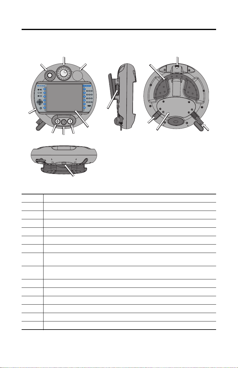
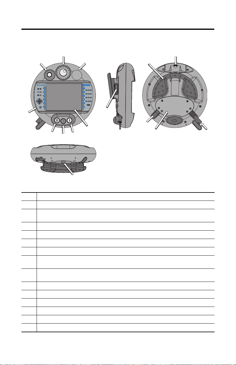
MobileView Machine Terminal MT750 Description
2
1
3
11
12
4
8
5
1 Potentiometer with 0-127 linear resolution (option)
2 Electronic handwheel, 50 pulses/rev -32768 to +32768 (option)
3 Emergency stop switch location (optional only on the MobileView Guard G750 Safety Terminals)
4 Membrane keypad with tactile feedback - standard Windows keyboard operation
5 Illuminated momentary push button, normally open, OFF marking, yellow LED (option)
6 3-position key switch (option)
7 Illuminated momentary push button, normally open, ON marking, yellow LED (option)
8 7.7 inch VGA (640 x 480 pixels) passive matrix color LCD display with analog resistive touch
9 Enabling switch location - one each side of handle (optional only on the MobileView Guard G750
10 IrDA keyboard/printer interface, 9600 or 115.2K baud
11 Handle for left or right-hand operation
12 Single slot PC card interface for Type I, II and III cards (option)
13 Strain relief for connection cable (shipped with cable)
14 Back cover to connection compartment
15 Plug for cable outlet when not used (meets degree protection IP54)
screen
Safety Terminals)
7
6
10
9
15
14
13
Publication 2727-QS003E-MU-P
Page 6
6 MobileView Machine Terminal MT750
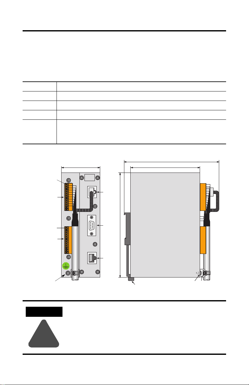
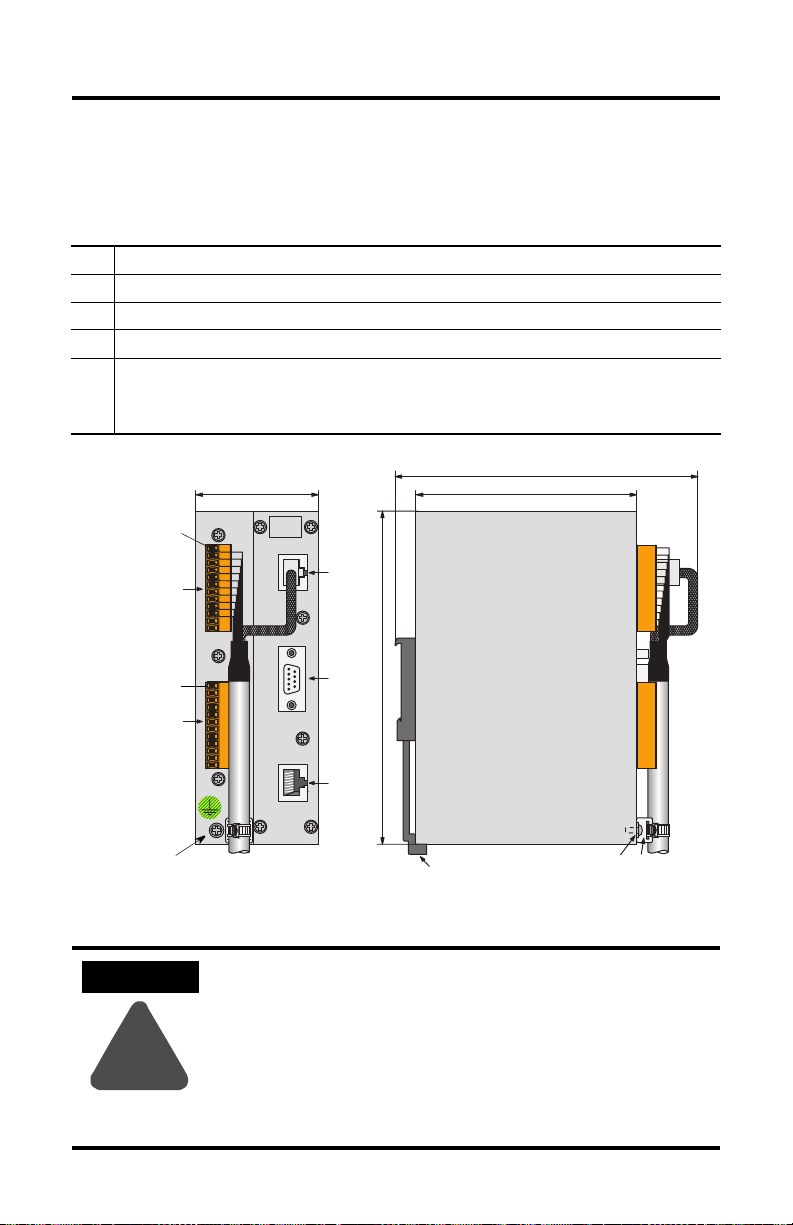
MobileView Junction Box Mounting and Wiring
The MobileView Junction Box (2727-MRJB1) integrates the MobileView terminal
into the control system and is mounted on a DIN rail.
S1 RJ-45 jack for connecting the MobileView data lines.
S2 9-pin DSUB female connector (for future use).
S3 RJ-45 jack to Ethernet network.
X1 12-pin male connector for connecting Junction Box Cable.
X2 12-pin male connector (shipped with female terminal block connector) for connecting the:
• 24V dc power supply
• emergency stop switch (used only on MobileView Guard G750 Terminals)
• enabling switches (used only on MobileView Guard G750 Terminals)
Pin 1, 24V dc
X1
(with Female
Terminal Block
Connector K3)
Pin 1, 24V dc
X2
(with Female
Terminal Block
Connector K4)
Grounding Screw
ATTENTION
!
60 mm (2.36 in)
24V DC
ON LY
+24V
TERM INAL IN
GND
ES1+
ES1-
ES2+
ES2-
ED1+
ED1-
ED2+
ED2-
+24V
GND
ES1+
ES1-
ES2+
ES2-
ED1+
ED1-
ED2+
ED2-
ETHERNET OUT
S1
RS422 OUT
S2
162 mm (6.4 in)
108 mm (4.25 in
S3
150 mm (5.91 in)
DIN Rail Latch
Grounding
Screw
The Junction Box and the MobileView terminal meet the safety class
III in accordance with EN 61131-2 and EN 50178.
When connecting the terminal, make sure all voltages connected to the
MobileView terminal are safety extra low voltages by using a safety
transformer or a similar facility.
Strain Relief
Publication 2727-QS003E-MU-P
Page 7
MobileView Machine Terminal MT750 7
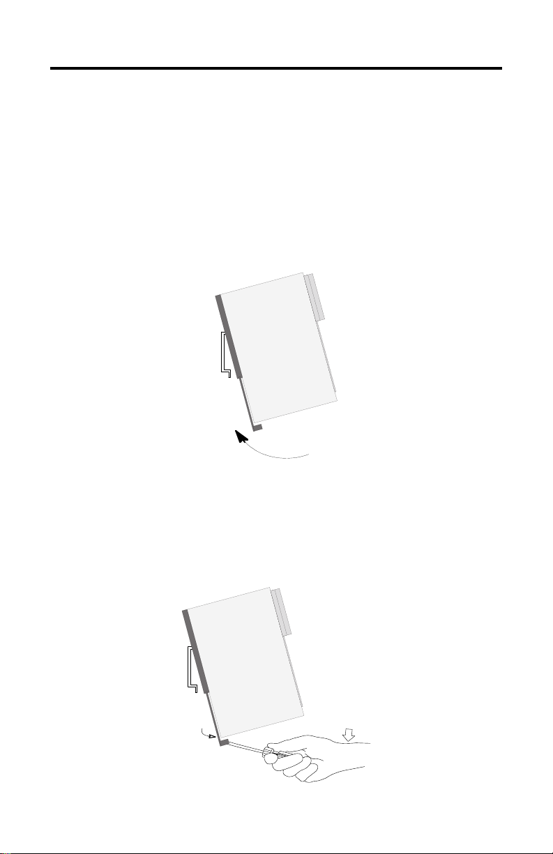
Mounting Junction Box on a DIN Rail
Mount the MobileView Junction Box within an enclosure using a DIN rail.
To install the Junction Box on a DIN rail:
1. Mount the DIN rail.
2. Hook the top slot over the DIN rail.
While pressing the Junction Box against the rail, snap the Junction Box into
position.
To remove your Junction Box from the DIN rail:
1. Place a screwdriver in the DIN rail latch at the bottom of the Junction Box.
2. Holding the Junction Box, pry downward on the latch until the Junction Box
is released from the DIN rail.
Publication 2727-QS003E-MU-P
Page 8
8 MobileView Machine Terminal MT750
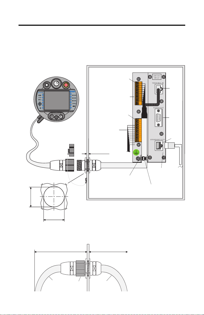
Connecting the MobileView to the Junction Box
The following illustration shows how the MobileView terminal connects to the
Junction Box.
MobileView Terminal
ESC
7 8 9
5 6
4
3
1 2
.
-
0
MobileView
Connection Cable
Connector Cutout
24 mm
(0.94 in)
(1.0 ± 0.0039 in)
25 ± 0.1 mm
n
Ru
KETOP
Dust Cover
Typical Control Cabinet
Pin 1, 24V dc
r
o
r
Er
Terminal Connections
X1/K3
MobileView
Pin 1, 24V dc
X2/K4
Safety Equipment
Connections (For
MobileView G750 only)
maximum wall
thickness 5 mm (0.2 in)
Junction Box
+24V
TERM INAL IN
GND
ES1+
ES1-
ES2+
ES2-
ED1+
ED1-
ED2+
ED2-
+24V
GND
ES1+
ES1-
ES2+
ES2-
ED1+
ED1-
ED2+
ED2-
ETHERNET OUT
24V DC
ON LY
RS 422 OUT
S1
S2
S3
Junction Box Cable
K1
2 m (6.5 ft)
Use Grounding
Screw to Connect
Earth Ground to the
Junction Box
10 Base-T
Connection to
Ethernet Network
Junction Box Cable
Wire Tie
Cable Clearance on Both Sides of Enclosure Wall
130 mm (5.12 in)
Connection
Cable
Publication 2727-QS003E-MU-P
K1
Connection
108 mm (3.94 in)
Junction Box
Cable
Page 9
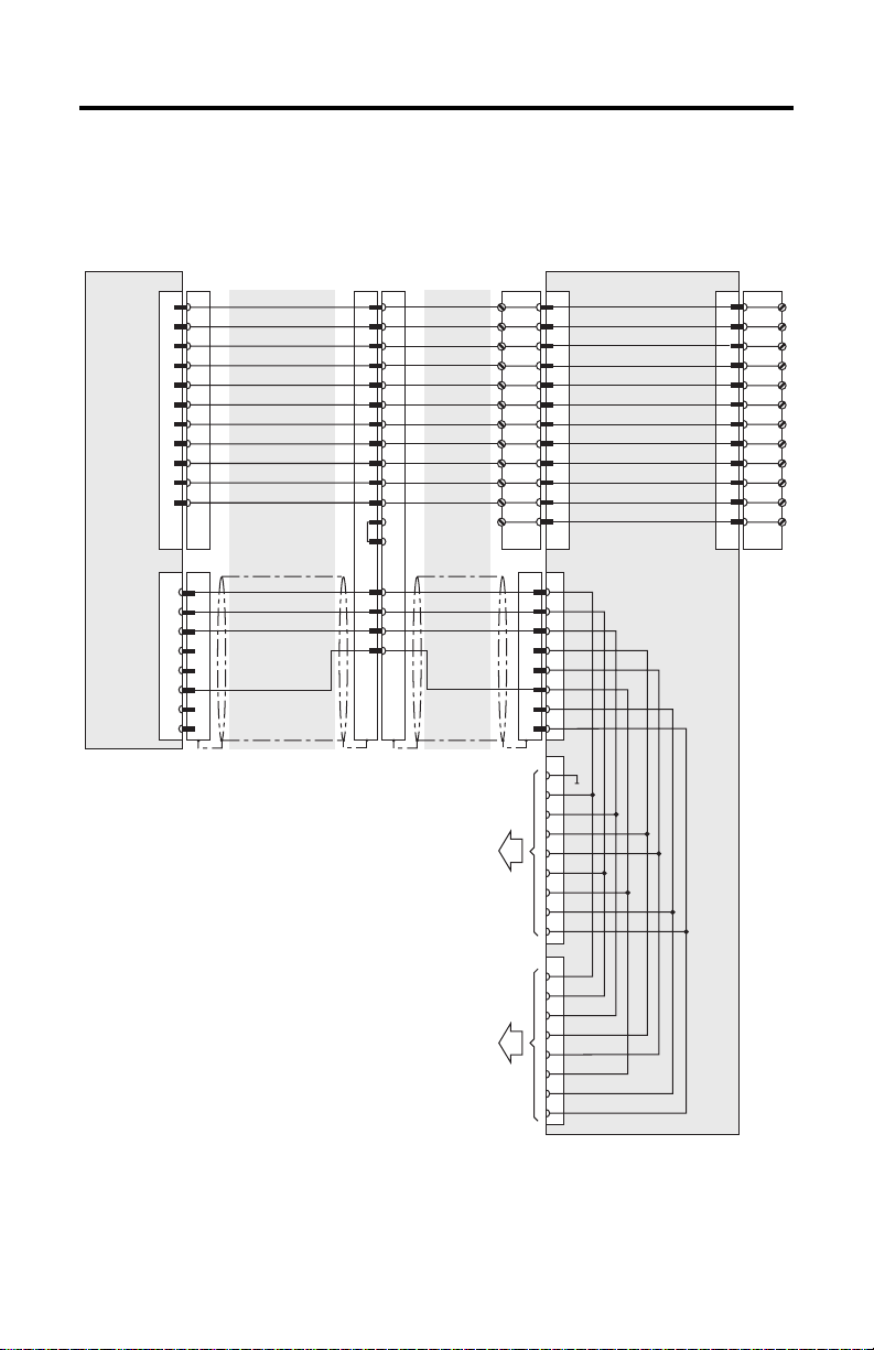
Junction Box Pinout and Wiring
MobileView Machine Terminal MT750 9
MobileView
S19
S4
Connection Cable
K3
6
7
8
9
10
11
1
2
3
4
5
K2
1
2
3
6
MobileView
pink
blac k
green-brown
white-green
grey-pink
red-blue
brown
yellow
green
grey
violet
blue
white
orange
red
* Junction Box connections are for
connection to MobileView Guard G750
Terminals only.
MobileView
Junction Box Cable
K1
1
2
3
4
5
6
7
8
12
17
11
9
10
13
14
15
16
pink
blac k
green-brown
white-green
grey-pink
red-blue
brown
yellow
green
grey
violet
blue
white
orange
red
Future Use
To Ethernet Network
K3
TD+
TDRD+
RD-
X1
1
2
3
4
5
6
7
8
9
10
11
12
K2
S1
1
2
3
4
5
6
7
8
S2
1
2
3
4
5
6
7
8
9
S3
1
2
3
4
5
6
7
8
Junction Box
24V DC
GND_IN
E-Stop, circuit 1, pos.
E-Stop, circuit 1, neg.
E-Stop, circuit 2, pos.
E-Stop, circuit 2, neg.
Enbl. sw. circ. 1, pos
Enbl. sw. circ. 1, neg
Enbl. sw. circ. 2, pos
Enbl. sw. circ. 2, neg
Not used
Not used
*
*
*
*
*
*
*
*
X2 K4
1
2
3
4
5
6
7
8
9
10
11
12
+24V
GND
ES1+
ES1-
ES2+
ES2ED1+
ED1ED2+
ED2-
Publication 2727-QS003E-MU-P
Page 10
10 MobileView Machine Terminal MT750
Power Supply Requirements
Electrical Specifications
24V dc Power Supply Use a 24V dc Safety Extra Low Voltage power supply.
Grounding Connect Earth Ground to the Junction Box using the Earth
Supply Voltage Range: 18V dc to 32V dc
Current Consumption: 300mA at 24V dc
Peak Inrush Current: 5.6 A maximum
Ground Screw (shown on page 8).
ATTENTION
!
• The device meets the safety class III in accordance with EN
61131-2 and EN 50178. The 24V power supply for the
equipment must provide appropriate isolation between
safety-extra-low-voltage circuits and dangerous-contact
voltage circuits (for example, by safety transformers or
similar facilities).
• The power supply circuit must be protected with a 3.15 A
fuse.
• The nominal supply voltage directly of the MobileView
terminal (without the MobileView Connection Cable) is
+24V dc (supply voltage range: 18 to 32V dc).
Typical current consumption is:
- 300 mA at 24V dc
-400 mA at 18V dc
When planning the power supply, take into account the
voltage drop on the Connection Cable.
Specification of power supply lines in this cable:
Cross section: AWG24 (0.24 mm2)
Material: zinc-coated copper strand
Line resistance:
<90 Ohm/km ( <145 Ohm/mile)
Publication 2727-QS003E-MU-P
Page 11
MobileView Machine Terminal MT750 11
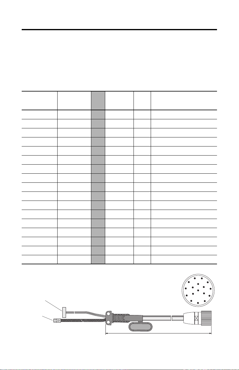
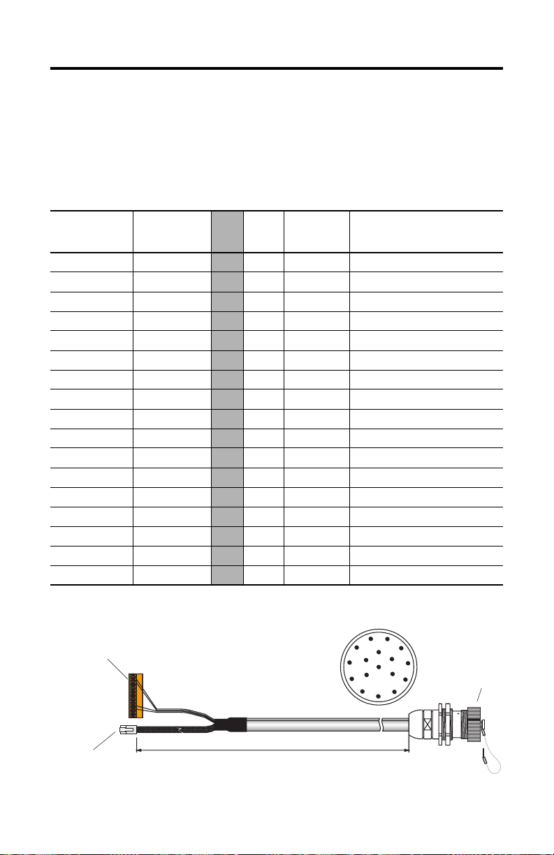
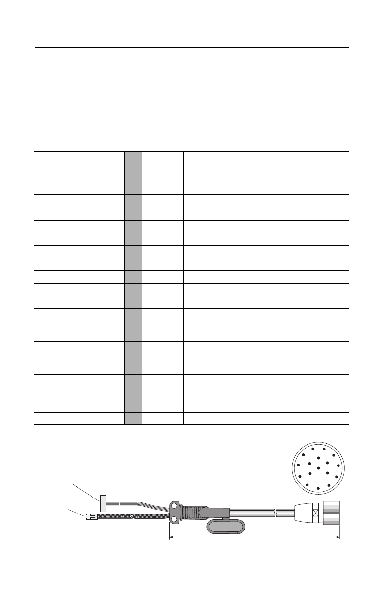
MobileView Connection Cable
The MobileView Connection Cable (2727-MRTxx) connects the MobileView
terminal to the Junction Box Cable. The Connection Cable is 5, 10, 15, or 20 meters
(16.4, 32.8, 49.2, or 65.6 feet). This cable withstands water, cleaning agents, motor
oil, drilling oils, grease, lubricants and condensates containing hydrochloric acid.
K1
17-pin Circular
Connector Pin #
Connection
Cable
Wire Color
1pink
2black
3 green-brown
4 white-green
5 grey-pink
6 red-blue
7brown
8yellow
12 green
17 grey
9 bridge to pin 10
10 bridge to pin 9
11 violet
13 blue
14 white
15 orange
16 red
K3, 11-pin
Female
Connector
-->> 6 - 24V DC
-->> 7 - GND_IN
-->> 8 - E-stop, circuit 1, positive *
-->> 9 - E-stop, circuit 1, negative *
-->> 10 - E-stop, circuit 2, positive *
-->> 11 - E-stop, circuit 2, negative *
-->> 1 - Enabling switch, circuit 1, pos. *
-->> 2 - Enabling switch, circuit 1, neg. *
-->> 3 - Enabling switch, circuit 2, pos. *
-->> 4 - Enabling switch, circuit 2, neg. *
-->> - - Not Used
-->> - - Not Used
-->> 5 - Not Used
-->> - 1 TD+ (transmit)
-->> - 2 TD- (transmit)
-->> - 3 RD+ (receive)
-->> - 6 RD- (receive)
* For connection to MobileView Guard G750 terminals only.
K3, 11-pin
female connector to S19
at MobileView terminal
K2, 8-pin RJ-45
jack to S4 at
MobileView
terminal
K2,
8-pin
Description
RJ-45
K1, 17- pin circul ar connector
view from connector side
Signal
11
1
10
9
8
2
12
16
13
17
3
14
15
4
5
7
6
5, 10, 15, or 20 meters (6.4, 32.8, 49.2, or 6 5.6 feet)
Publication 2727-QS003E-MU-P
Page 12
12 MobileView Machine Terminal MT750
MobileView Junction Box Cable
The MobileView Junction Box Cable (2727-MREX1) connects the Junction Box to
the circular jack in the wall of the enclosure. The cable length is 2 meters (6.5 feet).
When the MobileView terminal is not connected to the Junction box, the dust cover
provides protection for the 17-pin connector.
K1, 17-pin
Circular Jack
Pin #
1pink
2black
3 green-brown
4 white-green
5 grey-pink
6 red-blue
7brown
8yellow
12 green
17 grey
910 11 violet
13 blue
14 white
15 orange
16 red
MobileView
Junction Box
Wire Color
K2,
8-Pin
RJ-45
-->> - 1 24V DC
-->> - 2 GND_IN
-->> - 3 E-stop, circuit 1, positive*
-->> - 4 E-stop, circuit 1, negative*
-->> - 5 E-stop, circuit 2, positive*
-->> - 6 E-stop, circuit 2, negative*
-->> - 7 Enabling switch, circuit 1, pos.*
-->> - 8 Enabling switch, circuit 1, neg.*
-->> - 9 Enabling switch, circuit 2, pos.*
-->> - 10 Enabling switch, circuit 2, neg.*
-->> - - Not Used
-->> - 12 Not Used
-->> - 11 Not Used
-->> 1 - TD+ (transmit)
-->> 2 - TD- (transmit)
-->> 3 - RD+ (receive)
-->> 6 - RD- (receive)
* For connection to MobileView Guard G750 terminals only.
K3, 12-pin
connector for
terminal block X1
at Junction Box
K3, 12-Pin
Terminal
Block
K1, 17-pin circular jack
view from connector side
Signal
Description
1
11
2
12
13
3
17
14
4
5
6
10
16
9
15
8
7
Dust Cover
K2, 8-pin RJ-45
jack (Ethernet) for
S1 at Junction Box
Publication 2727-QS003E-MU-P
2 meter (6.5 ft)
K1, 17-pin circular jack
mounts to enclosure
Page 13
MobileView Machine Terminal MT750 13
MobileView Terminal
This section provides details on:
• How to remove the back cover of the MobileView terminal
• Ethernet connection
• Using the PC Card slot
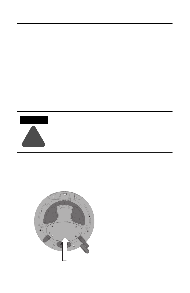
Removing the Back Cover
This section shows how to remove the back cover of the MobileView terminal.
Once the back cover is removed you have access to the area which contains all of
the connectors.
ATTENTION
Turn off the power supply before removing the back cover of
the MobileView terminal.
When the back cover is removed, the MobileView terminal is
sensitive to electrostatic discharge.
!
1. Place the terminal on a stable, flat surface.
2. Remove the 6 screws that secure the back cover to the terminal.
3. Carefully lift off the back cover and set aside.
Back Cover
Publication 2727-QS003E-MU-P
Page 14
14 MobileView Machine Terminal MT750
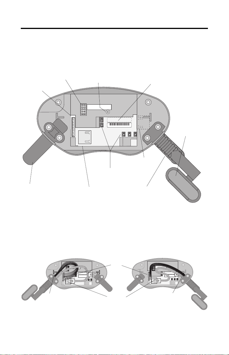
The following illustration shows what the connection area of the MobileView
terminal looks like with the back cover removed.
RS-232 Port
for downloading software.
Main connector (S19)
for power supply and
control lines
Reset Button
for rebooting Windows CE.
All data not flushed to Registry or
saved to Flash Storage is lost.
pin 1
Serial
S19
port
S4
Ethernet
Reset
B5
B4
00:60:B5:06:00:01
2250-00001
AABBCCDDEEFF
B2 B6 B3
Ethernet Label
Ethernet (Mac) Address
S6,
COM -Modul
Cable Tag
Allows the terminal to
be uniquely identified.
Connector (not used)
Position of switches does not
affect terminal operation (for
future use)
Important: Install plug on
unused MobileView
Connection Cable outlet.
Ethernet connector (S4)
for data exchange
Strain Relief
for connecting MobileView
Connection Cable (on left or right side)
Relocating MobileView Connection Cable
The MobileView Connection Cable can be attached on the right or left side of the
terminal for right or left-hand operation. To relocate the cable, simply grasp the
strain relief and/or the plug and slide off of mount with a rocking motion.
Attaching Cable on Right
Avoid routing cable
over T-support.
S6,
Connector
COM -Modul
S4, Ethernet Connector
S19
Main
Attaching Cable on Left
Avoid routing cable
over T-support.
S6,
COM-Modul
Important: Make sure the K3, 11-pin female connector clicks completely into S19, Main Connector when
plugged in. Ensure proper seating of K2, 8-pin RJ-45 jack into S4, Ethernet Connector. Avoid routing cable
over T-supports. After routing the cable, secure the back cover to the terminal with the 6 screws. Tighten
screws to a torque of 0.5 Nm to maintain IP54 degree protection.
Publication 2727-QS003E-MU-P
Page 15
MobileView Machine Terminal MT750 15
Ethernet Connection
The MobileView terminal is equipped with a 10Base-T interface which supports
TCP/IP protocol at 10MBaud for half-duplex communications.
The Ethernet connector at S3 on the Junction Box provides a connection to an
Ethernet network. The connector uses an 8-pin modular jack connector. Pinouts are
as follows:
Pin # Ethernet Signal
1TD+
2TD3RD+
4 Not Used
5 Not Used
6RD7 Not Used
8 Not Used
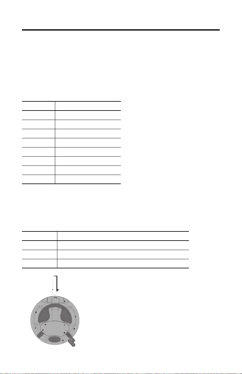
Using the PC Card Slot
The PC card slot is a factory installed option and supports Type I, II, and III PC
cards. The following PC cards are available from Allen-Bradley. The terminal does
not support SRAM cards, Cardbus cards, or cards that use 12 volts for programming.
Catalog No. Description
2711-NM28 8M flash ATA card for storing applications.
2711-NM216 16M flash ATA card for storing applications.
2711-NM232 32M flash ATA card for storing applications.
PC Card
Compartment
Publication 2727-QS003E-MU-P
Page 16
16 MobileView Machine Terminal MT750
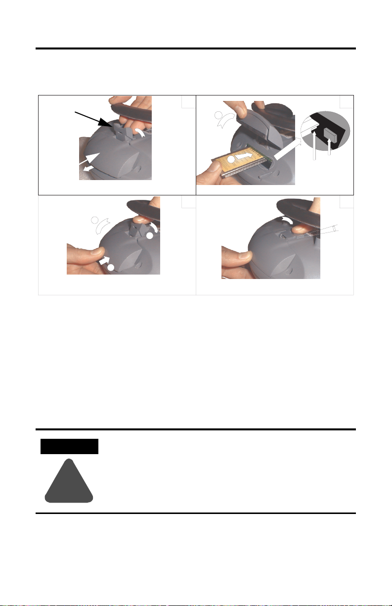
Inserting the PC Card
Locking Lever
PC Card Cover
a
c
b
1
a
b
3
Unlocking PC card cover (see illustration 1).
a. Lay the MobileView with the display facing down onto a flat, clean table
(preferably on ESP pad). Take care not to damage the terminal and its
elements.
b. Lift up on locking lever until PC Card Cover is released.
4. Inserting PC card (see illustration 2).
a. Lift the cover up.
b. Insert the PC card until it locks in and the ejection button pops out.
Ejection button
Must snap
completely.
2
4
ATTENTION
Verify that the corner of the PC card (with the notch) is
inserted into the slot on the side of the ejection button.
Check the condition and position of the cover seal before
closing the PC card cover.
!
5. Close and lock the cover (see illustration 3).
6. Press the cover down until it snaps in completely (see illustration 4).
Publication 2727-QS003E-MU-P
Page 17

MobileView Machine Terminal MT750 17
Removing the PC Card
1
1
3
2
1. Open the PC card cover. Refer to Inserting the PC Card on page 16 for
procedures.
2. Press the ejection button on the PC card slot.
3. Remove the PC Card.
4. Close and lock the cover.
5. Press the cover down until it snaps in completely.
Publication 2727-QS003E-MU-P
Page 18
18 MobileView Machine Terminal MT750
Startup/Power On
1. Attach the MobileView Connection Cable to the Junction Box Cable as
shown on page 8. Tighten threaded coupling until it is finger tight.
2. Check the MobileView terminal for a start-up screen.
If the start-up screen does not appear, check the 24V dc power source and
cable connections at the Junction Box and MobileView terminal.
TIP
An icon for RSView ME software appears on the MobileView
2727-M7P20D1Q2 and 2727-M7P20D1Q3 start-up screens only.
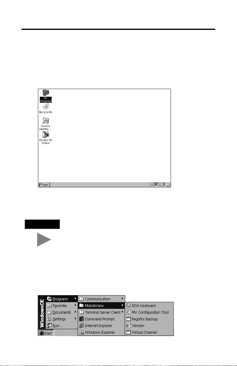
Hardware Configuration
1. From the task bar, select Start>Programs>MobileView>MV
Configuration Tool.
Publication 2727-QS003E-MU-P
Page 19
MobileView Machine Terminal MT750 19
The Config Tool dialog opens with the default tab selected. Adjust display
touch screen and device settings, as desired. Refer to publication
2727-UM003, MobileView MT750 User Manual for details.
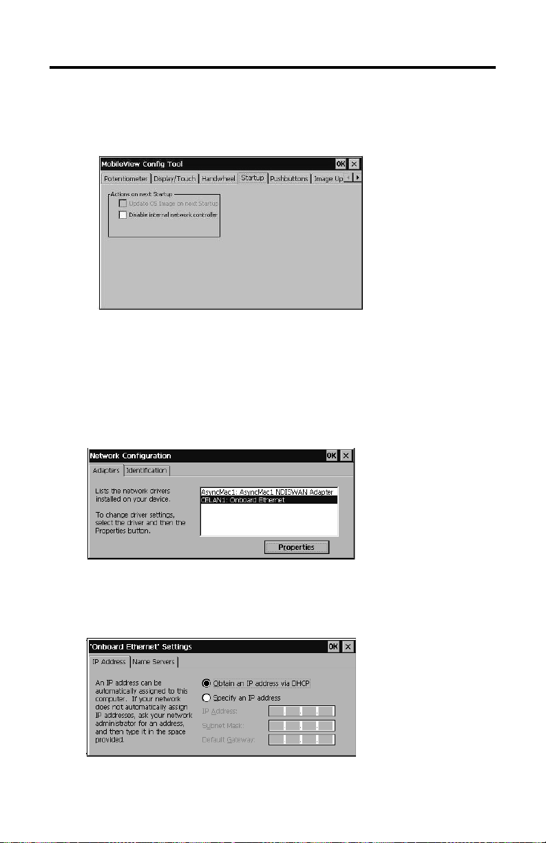
Ethernet Network Configuration
To configure the onboard Ethernet communications hardware of your MobileView
terminal:
1. Tap the Start button and select Settings>Control Panel.
2. Double-tap the Network icon.
3. Tap the Adapters tab in the Network Configuration dialog.
4. Select the CELAN1:Onboard Ethernet from the list of drivers, then tap the
Properties button.
Publication 2727-QS003E-MU-P
Page 20
20 MobileView Machine Terminal MT750
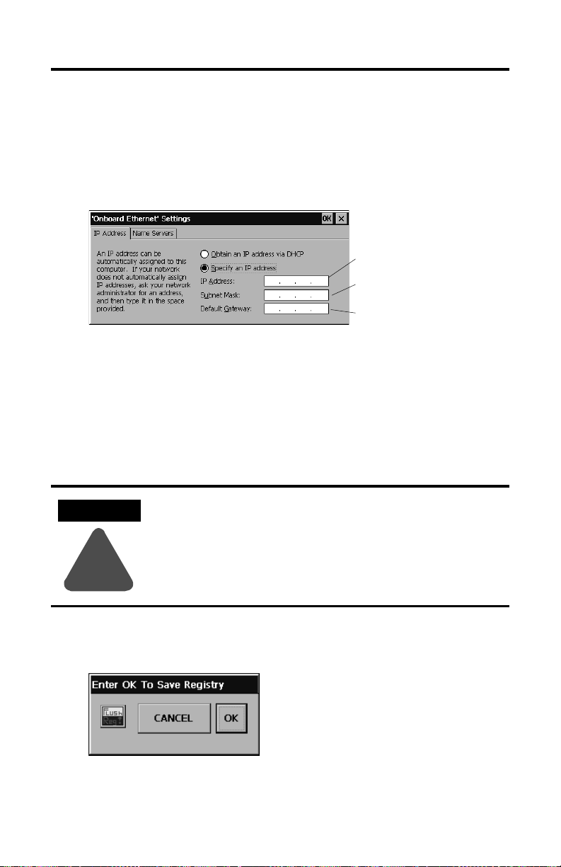
5. Tap the IP Address tab and select either Obtain an IP Address via DHCP
or Specify an IP Address, depending on your network configuration. If you
select Specify an IP Address, complete the 3 text boxes with information
from your network administrator or ISP. Use the on-screen input panel to
enter the text. You can access the input panel by tapping the Stylus icon on
the task bar.
IP Address must be a unique
address on the LAN.
Subnet Mask must be identical
to the server subnet mask.
Default Gateway is optional.
6. Tap OK in the settings dialog. A notification window appears prompting you
to either remove and reinstall your card or restart the device for the new
settings to take effect. Tap the OK button in notification window.
7. Tap OK on the Network Configuration dialog and close the Control Panel.
Saving Registry Settings
ATTENTION
Any hardware configuration or Ethernet network configuration
changes must be saved to the registry or they will be lost
during a MobileView terminal power cycle.
!
To save the current registry settings:
1. Tap the Start button and select Programs>MobileView>Registry Backup.
2. To save the registry, tap the OK button. Saving the registry may take up to
15 seconds. The registry backup will automatically close.
Publication 2727-QS003E-MU-P
Page 21
MobileView Machine Terminal MT750 21
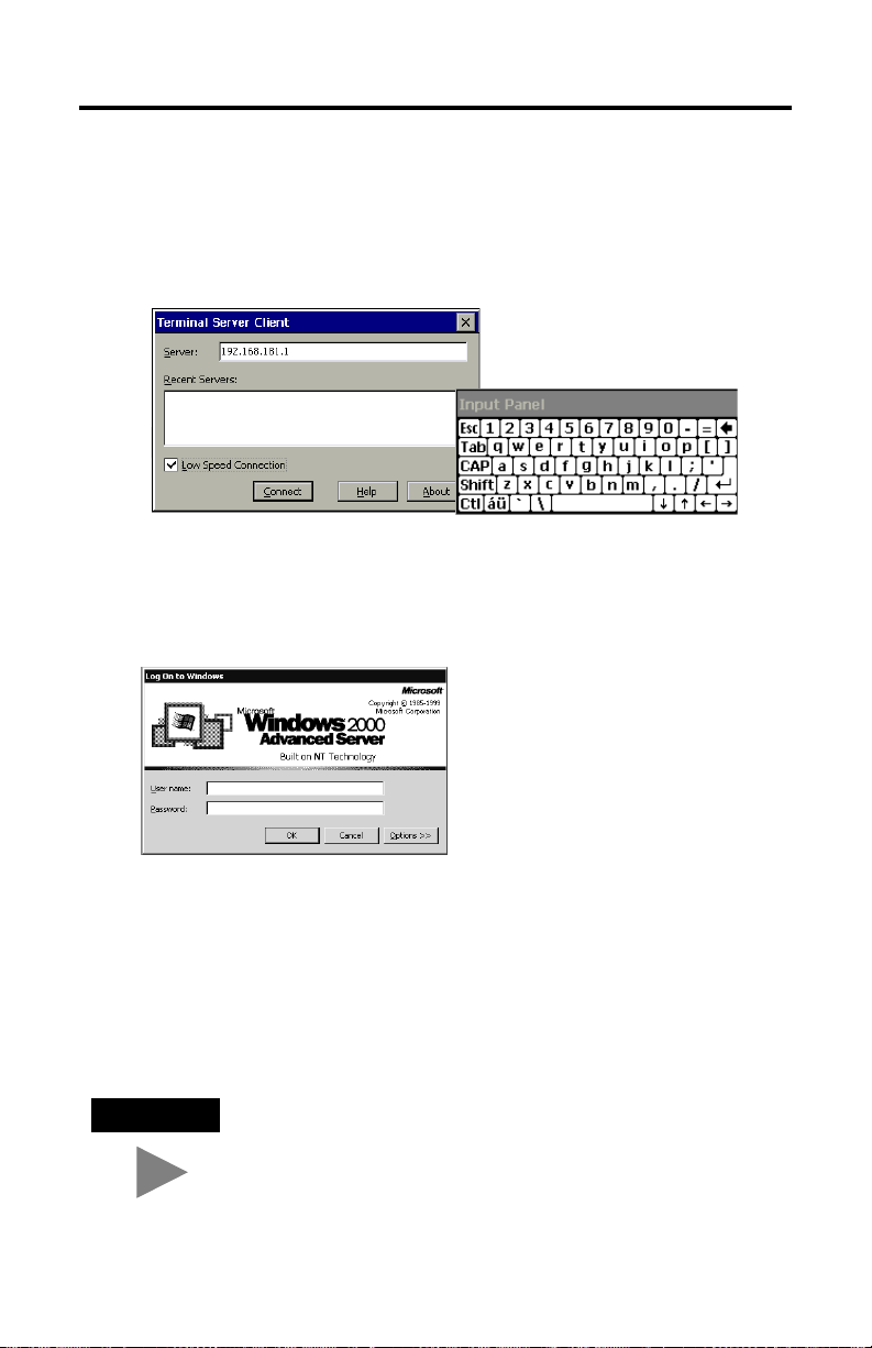
Starting Terminal Services
To connect to a terminal server as a CE client:
1. Double-tap the Terminal Server Client shortcut on the desktop of the
MobileView terminal or select the Terminal Server Client application from
the Programs>Terminal Server Client folder on the Start menu.
2. Enter the Terminal Server’s Name or a valid TCP/IP address in the Server
box using the on-screen input panel or select a server name or address from
the Recent Servers box.
3. Tap the Connect button. A server log on window similar to the one below
appears.
4. Enter your user name and password to operate as an active CE client.
Shutdown/Power Off
1. Close down all applications that are running on CE client.
2. Tap the Start button on the CE client task bar. Select Shutdown and then
Log Off to disconnect from the terminal server.
3. Remove 24V dc power from the MobileView junction box or disconnect the
MobileView connection cable from the junction box cable.
TIP
Time/Date/Regional Setting information is not saved during a
reboot.
Publication 2727-QS003E-MU-P
Page 22
22 MobileView Machine Terminal MT750
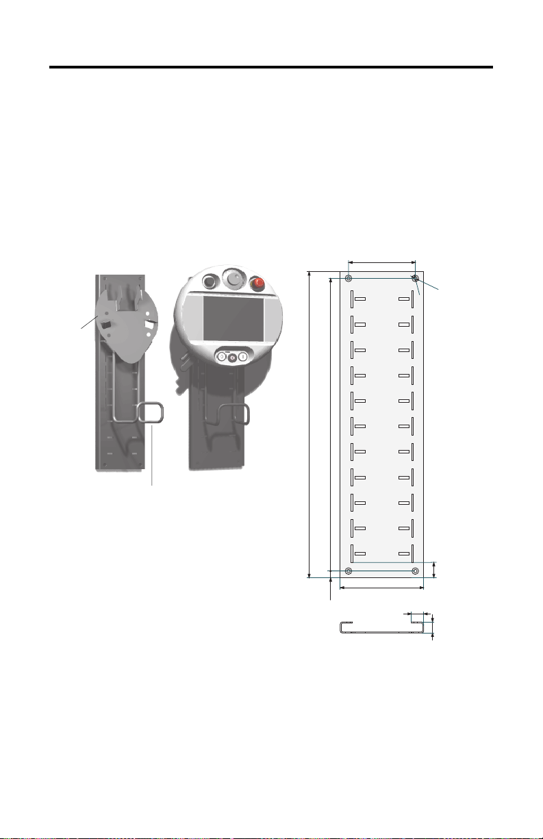
Mounting Bracket Installation
The MobileView Mounting Bracket (catalog number 2727-MRMB1) is used for
stationary operation or storage of the terminal. The following illustration shows the
mounting bracket with and without the terminal mounted.
The carrier is adjustable in 8 positions over a height of 320 mm (12.6 in). It is
important to attach the carrier at all 4 points on the height adjustment plate. Mount
the cable holder on the carrier using the screws delivered with the bracket.
Height Adjustment Plate
Carrier
Connection Cable Holder
Plate Dimensions and Mounting Holes
550 mm (21.65 in)
MobileView
120 mm (4.72 in)
526 mm (20.71 in)
150 mm (5.91 in)
22 mm (0.87 in)
12 mm (0.47 mm)
Use suitable screws (not shipped with product) to mount the plate.
6
m
m
1
d
2
i
a
.
(
0
m
.
2
4
m
d
i
a
i
n
)
.
(
0
.
4
7
i
n
)
28 mm
(1.1 in)
20 mm
(0.79 in)
Publication 2727-QS003E-MU-P
Page 23

MobileView Machine Terminal MT750 23
European Communities (EC) Directive Compliance
The product has a CE mark and is approved for installation within the European
Union and EEA regions. It has been designed and tested to meet the following
directives.
EMC Directive
This product is tested to meet the Council Directive 89/336/EC Electromagnetic
Compatibility (EMC) by applying the following standards, in whole or in part,
documented in a technical construction file:
• EN 61000-6-4 Generic Standards - Emission Standard for Industrial
Environments
• EN 61000-6-2 EMC - Generic Standards - Immunity for Industrial
Environments
• EN 61131-2 - Programmable Controllers Part 2 - Equipment Requirement and
Tests
This product is intended for use in an industrial environment.
A Declaration of Conformity is available upon request.
Standards and Agency Certifications
General
UL 508 Industrial Control Equipment
CSA C22.2 No. 14 Industrial Control Equipment
C-Tick Marked for all applicable acts.
Electromagnetic Compatibility (EMC)
EN 61000-6-4:2001 EMC - generic emission standard for industrial environment
EN 61000-6-2:2001 EMC - generic immunity standard for industrial environment
IEC 61131-2 final draft chapt 7+8 Programmable Controllers - Equipment requirements and test
Operating Safety
IEC 61131-2, EN 61131-2:1994 +
A11:1996 + A12:2000
EN 50178:1997 Safety Low Voltages
Electronic equipment for use in power installations
Publication 2727-QS003E-MU-P
Page 24
24 MobileView Machine Terminal MT750
MobileView Machine Terminal MT750 Configurations
Features 2727-M7P20D1P1 2727-M7P20D1Q2 2727-M7P20D1Q3
7.7 Inch VGA Display Yes
IrDA Interface Yes
3-Position Enable Switch No
2-Circuit E-Stop (Position 3) No
Memory 16MB
PC Card Slot No Yes
Communications 10Base-T Ethernet
Operating Elements No No
Windows CE OS Yes
RSView Machine Edition No
Thin Client Application Yes
DRAM/32MB Flash
64MB DRAM/64MB Flash
Push Button with OFF
Marking - Position 5
Key Switch - Position 6
Push Button with ON
marking - Position 7
Yes
Publication 2727-QS003E-MU-P
Page 25

MobileView Machine Terminal MT750 25
Accessories
Catalog Number Description
2727-MRT5 MobileView Connection Cable (5 meter /16.4 ft) - connects the MobileView MT750
2727-MRT10 MobileView Connection Cable (10 meter /32.8 ft) - connects the MobileView MT750
2727-MRT15 MobileView Connection Cable (15 meter /49.2 ft) - connects the MobileView MT750
2727-MRT20 MobileView Connection Cable (20 meter/65.6 ft) - connects the MobileView MT750
2727-MRJB1 MobileView Junction Box - provides controller, Ethernet, power supply, emergency
2727-MREX1 MobileView Junction Box Cable (2 meter / 6.5 ft) - connects the MobileView
2727-MRC1 MobileView Download Cable (4 meter /13.1 ft) - connects between the MobileView
2727-MRMB1 MobileView Mounting Bracket for stationary operation or storing the MobileView
2727-MRSDK1 MobileView SDK file set for Windows CE development.
terminal to the Junction Box cable.
terminal to the Junction Box cable.
terminal to the Junction Box cable.
terminal to the Junction Box cable.
stop switch, and enabling switch connections.
Connection Cable to the Junction Box.
MT750 terminal to a PC.
MT750 terminal.
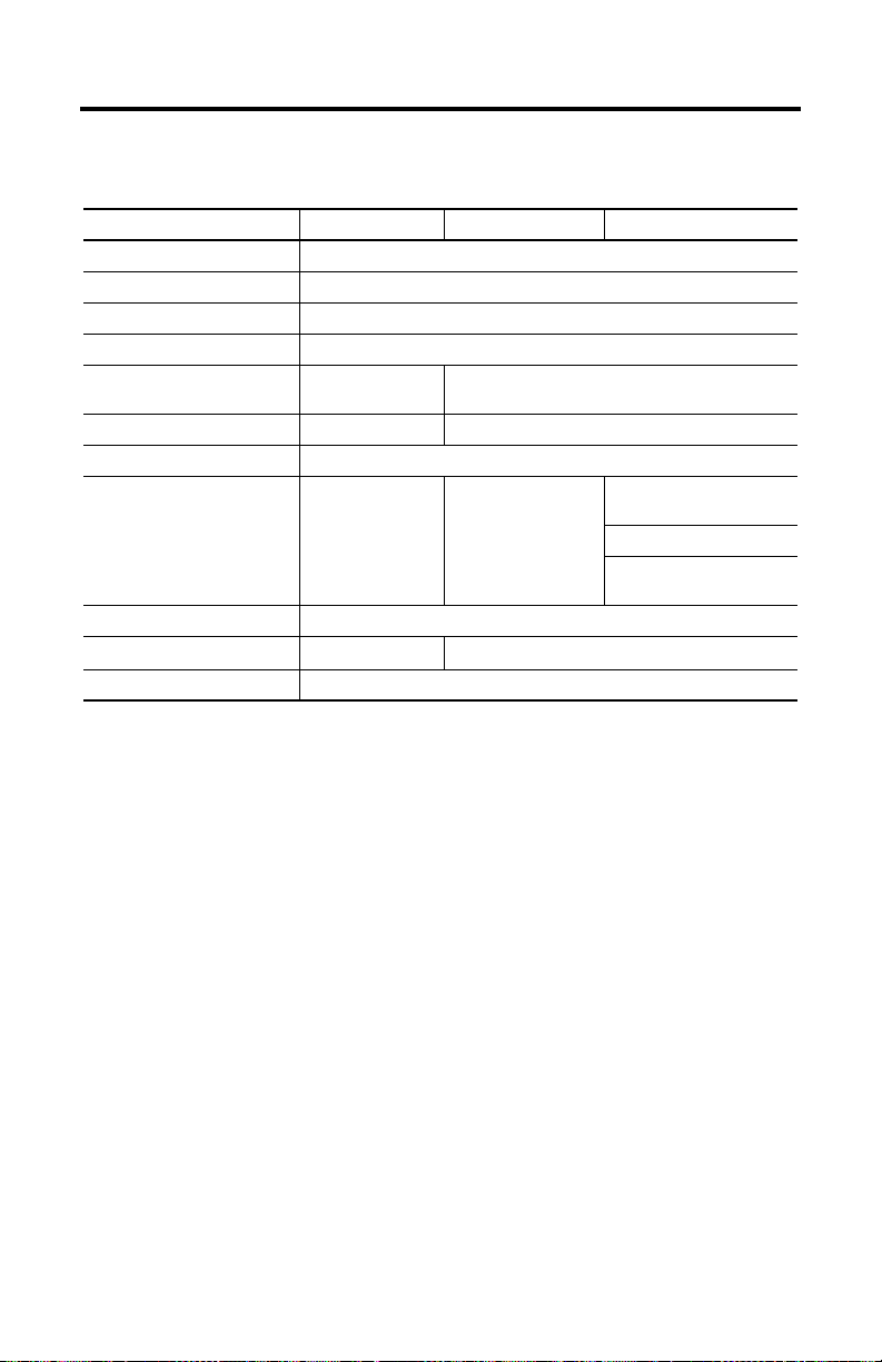
Specifications
General
Processor Intel StrongARM SA-1110/206 MHz
Operating System Microsoft Windows CE, Version 4.1
Memory 2 sizes: 16M DRAM/32M Flash or
Display Passive LCD 7.0-inch VGA with 256 colors
Touch Screen 7.7-inch analog resistive
Keypad Stainless steel dome membrane switches with tactile
Housing Twin shell
Dimensions
Diameter
Depth without handle
Depth with handle
Weight 1550 grams (3.42 lbs) - without options
64M DRAM/64M Flash
feedback
Resistive to grease, oil, lubricants, alcohol
Silicone-free
Flammability class: UL 94-V0
290 mm (11.42 inches)
80 mm (3.15 inches)
130 mm (5.12 inches)
Publication 2727-QS003E-MU-P
Page 26

26 MobileView Machine Terminal MT750
Electrical
Nominal Supply Voltage 24V dc
Supply Voltage Range 18V dc to 32V dc
Input Current 300mA maximum
Peak Inrush Current 5.6A maximum
Power Supply 10 ms minimum holdup time
Environmental
Operating Temperature
Storage Temperature
Relative Humidity (non-condensing)
Protection Degree IP54
Vibration (operating) 10 to 57 Hz, 0.15mm p-p
Shock (operating) 25 G / 11 ms IEC 60068-2-27
(EN 61131-2:1994 + A11:1996 + A12:2000 and
EN 50178:1997)
° to 50°C (32° to 122°F)
0
° to +70°C (-13° to +158°F)
-25
5 to 95% at 0 to 50
57 to 150 Hz, 2G Peak
°C (32° to 122°F)
Publication 2727-QS003E-MU-P
Page 27

Guide de mise en route
MobileView Machine Terminal MT750
(Références 2727-M7P20D1P1, 2727-M7P20D1Q2, 2727-M7P20D1Q3)
Français
Pour des informations plus détaillées sur le MobileView Machine Terminal MT750,
consultez la publication 2727-UM003.
Vous pouvez télécharger une version électronique gratuite de la publication
2727-UM003 à partir :
• du CD d’installation ;
• www.support.rockwellautomation.com
www.theautomationbookstore.com
Sommaire . . .
Informations importantes destinées à l’utilisateur ......................................................... 28
Description du MobileView Machine Terminal MT750 ................................................... 29
Montage et câblage du boîtier de raccordement MobileView ....................................... 30
Démontage du capot arrière ............................................................................................ 37
Connexion Ethernet .......................................................................................................... 39
Utilisation du logement pour carte PC ............................................................................. 39
Démarrage/Mise sous tension ........................................................................................ 42
Configuration matérielle .................................................................................................. 42
Configuration du réseau Ethernet .................................................................................... 43
Enregistrement des paramètres de la base de registres ................................................ 44
Démarrage des services Terminal Server ........................................................................ 45
Arrêt/Mise hors tension .................................................................................................. 45
Installation du support de fixation ................................................................................... 46
Conformité aux directives européennes (CE) ................................................................... 47
Normes et certifications .................................................................................................. 47
Configurations du MobileView Machine Terminal MT750 ............................................. 48
Accessoires ...................................................................................................................... 49
Spécifications .................................................................................................................. 49
Publication 2727-QS003E-MU-P
Page 28
28 MobileView Machine Terminal MT750
Informations importantes destinées à l’utilisateur
En raison de la diversité des utilisations des produits décrits dans la présente
publication, les personnes qui en sont responsables doivent s’assurer que toutes les
mesures nécessaires ont été prises pour que l’application et l’utilisation des produits
soient conformes aux exigences de performance et de sécurité, ainsi qu’aux lois,
règlements, codes et normes en vigueur.
Les illustrations, schémas et exemples de programmes contenus dans ce manuel
sont présentés à titre indicatif uniquement. En raison du nombre important de
variables et d’impératifs associés à chaque installation, la société Allen-Bradley ne
saurait être tenue pour responsable ni être redevable (y compris en matière de
propriété intellectuelle) des suites d’utilisation réelle basée sur les exemples et
schémas présentés dans cette publication.
La publication Allen-Bradley SGI-1.1, « Safety Guidelines for the Application,
Installation and Maintenance of Solid-State Control » (disponible auprès de votre
agence commerciale Allen-Bradley), décrit certaines différences importantes entre
les équipements électroniques et les équipements électromécaniques, qui devront
être prises en compte lors de l’application de ces produits, comme indiqué dans la
présente publication.
Toute reproduction totale ou partielle de la présente publication sans autorisation
écrite de la société Rockwell Automation est interdite.
Des remarques sont utilisées tout au long de ce manuel pour attirer votre attention
sur les mesures de sécurité à prendre en compte :
ATTENTION
Actions ou situations risquant d’entraîner des blessures
pouvant être mortelles, des dégâts matériels ou des pertes
financières.
!
Les mises en garde « Attention » vous aident à :
• identifier un danger ;
• éviter ce danger ;
• en discerner les conséquences.
IMPORTANT
Allen-Bradley est une marque commerciale de Rockwell Automation.
Publication 2727-QS003E-MU-P
Informations particulièrement importantes dans le cadre de
l’utilisation du produit.
Page 29
MobileView Machine Terminal MT750 29
Description du MobileView Machine Terminal MT750
2
1
3
11
12
4
8
5
1 Potentiomètre avec résolution linéaire de 0 à 127 (option)
2 Volant de manœuvre électronique, 50 impulsions/tour de -32768 à +32768 (option)
3 Emplacement pour bouton-poussoir d’arrêt d’urgence (en option uniquement sur les terminaux de
sécurité MobileView Guard G750)
4 Clavier tactile - Fonctionnalités Windows standard
5 Bouton-poussoir lumineux à impulsion, normalement ouvert, marquage désactivé, voyant jaune (option)
6 Commutateur à clé 3 positions (option)
7 Bouton-poussoir lumineux à impulsion, normalement ouvert, marquage activé, voyant jaune (option)
8 Ecran LCD couleur à matrice passive VGA 7,7 pouces (640 x 480 pixels) avec dalle tactile analogique
résistive
9 Emplacement pour interrupteur d’activation : un de chaque côté de la poignée (en option uniquement
sur les terminaux de sécurité MobileView Guard G750)
10 Interface IrDA imprimante/clavier, 9600 ou 115,2 Kbauds
11 Poignée pour gaucher ou pour droitier
12 Interface de carte PC à un logement pour cartes de type I, II et III (option)
13 Languette de réduction de tension pour câble de raccordement (livrée avec le câble)
14 Capot arrière du compartiment de raccordement
15 Obturateur pour la prise de câble non utilisée (degré de protection IP54)
7
6
10
9
15
14
13
Publication 2727-QS003E-MU-P
Page 30
30 MobileView Machine Terminal MT750
Montage et câblage du boîtier de raccordement MobileView
Le boîtier de raccordement MobileView (2727-MRJB1) intègre le terminal
MobileView au système de commande ; il est monté sur un rail DIN.
S1 Connecteur RJ-45 pour la connexion des lignes de données de MobileView.
S2 Connecteur femelle sub-D à 9 broches (pour utilisation ultérieure).
S3 Connecteur RJ-45 pour la connexion au réseau Ethernet.
X1 Connecteur mâle 12 broches pour le branchement du câble de connexion du boîtier de raccordement.
X2 Connecteur mâle 12 broches (fourni avec un connecteur bornier femelle) pour le branchement de:
• l’alimentation 24 V c.c. ;
• le bouton-poussoir d’arrêt d’urgence (sur les terminaux MobileView Guard G750 uniquement) ;
• les interrupteurs d’activation (sur les terminaux MobileView GuardG750 uniquement).
Broche 1, 24 V c.c
X1
(avec
connecteur
bornier
femelle K3)
Broche 1, 24V c.c
X2
(avec
connecteur
bornier
femelle K4)
Vis de mise à la terre
ATTENTION
!
60 mm
24V DC
ON LY
+24V
TERM INAL IN
GND
ES1+
ES1-
ES2+
ES2-
ED1+
ED1-
ED2+
ED2-
+24V
GND
ES1+
ES1-
ES2+
ES2-
ED1+
ED1-
ED2+
ED2-
ETHERNET OUT
S1
RS422 OUT
S2
162 mm
108 mm
S3
150 mm
Verrou du rail DIN
Vis de mise à la terre
Le boîtier de raccordement et le terminal MobileView sont
conformes à la sécurité de classe III selon les
normes EN 61131-2 et EN 50178.
Lors du branchement du terminal MobileView, vérifiez que
toutes les tensions connectées au terminal sont des basses
tensions de sécurité et qu’elles sont isolées de l’alimentation
basse tension par un transformateur de sécurité ou par un
système de sécurité similaire.
Languette de
réduction de
tension pour
câble
Publication 2727-QS003E-MU-P
Page 31

MobileView Machine Terminal MT750 31
Montage du boîtier de raccordement sur un rail DIN
Montez le boîtier de raccordement MobileView sur un rail DIN à l’intérieur d’une
armoire.
Pour installer le boîtier de raccordement sur un rail DIN :
1. Montez le rail DIN.
2. Accrochez la fente supérieure sur le rail DIN.
3. Exercez une pression sur le boîtier jusqu’à ce qu’il s’enclenche sur le rail
DIN.
Pour retirer le boîtier de raccordement du rail DIN :
1. Placez l’extrémité d’un tournevis dans le verrou du rail DIN, sous le boîtier
de raccordement.
2. Tout en maintenant le boîtier, faites levier sur le verrou à l’aide du tournevis
afin d’extraire le boîtier du rail DIN.
Publication 2727-QS003E-MU-P
Page 32

32 MobileView Machine Terminal MT750
Connexion du terminal MobileView au boîtier de raccordement
La figure suivante indique comment connecter le terminal MobileView au boîtier de
raccordement.
Terminal MobileView
ESC
7 8 9
5 6
4
3
1 2
.
-
0
Câble de
raccordement
du MobileView
24 mm
Découpe pour
le connecteur
25 ± 0,1 mm
r
o
n
r
Ru
Er
KETOP
Capuchon
anti-poussière
K1 :
Armoire de commande type
Broche 1, 24 V c.c
X1/K3
Connexions du
terminal MobileView
Broche 1, 24 V c.c
Connexions de
l’équipement de sécurité
(MobileView G750
uniquement)
Epaisseur maximale de
la paroi : 5mm
X2/K4
Câble de connexion du
boîtier de raccordement (2 m)
Utilisez la vis
de mise à la terre pour
relier le boîtier de
raccordement à la terre
Boîtier de raccordement
24V DC
ON LY
+24V
TERM INAL IN
GND
ES1+
ES1-
ES2+
ES2-
ED1+
ED1-
ED2+
ED2-
RS 422 OUT
+24V
GND
ES1+
ES1-
ES2+
ES2-
ED1+
ED1-
ED2+
ED2-
ETHERNET OUT
Connexion
10 Base-T au
réseau Ethernet
Attache du câble
de connexion
du boîtier de raccordement
S1
S2
S3
Dégagements nécessaires pour les câbles de chaque côté de la paroi de l’armoire
130 mm
Câble
de raccordement
Connexion
K1
108 mm
Câble de connexion
du boîtier de
raccordement
Publication 2727-QS003E-MU-P
Page 33

MobileView Machine Terminal MT750 33
Brochage et câblage du boîtier de raccordement
S19
K3
6
7
8
9
10
11
1
2
3
4
5
S4
K2
1
2
3
6
Câble de raccordement
du MobileView
rose
noir
vert-brun
blanc-vert
gris-rose
rouge-bleu
bru n
jaune
vert
gris
violet
bleu
blanc
orange
rouge
MobileView
Pour une utilisation ultérieure
* Les connexions du boîtier de
raccordement servent au raccordement
aux terminaux MobileView Guard G750
uniquement.
Câble de connexion du
boîtier de raccordement
MobileView
K1
1
2
3
4
5
6
7
8
12
17
11
9
10
13
14
15
16
rose
noir
vert-brun
blanc-vert
gris-rose
rouge-bleu
bru n
jaune
vert
gris
violet
bleu
blanc
orange
rouge
Vers réseau Ethernet
Boîtier de raccordement
K3
X1
24 V c.c.
1
Mise à la terre
2
Arrêt d’urg., circ. 1, pos.
3
Arrêt d’urg., circ. 1, nég.
4
5
Arrêt d’urg ., circ. 2, pos.
6
Arrêt d’urg ., circ. 2, nég.
Interrupt., circ. 1, pos.
7
8
Interrupt., circ. 1, nég.
9
Interrupt., circ. 2, pos.
10
Interrupt., circ. 2, nég.
11
Non utilisé
12
Non utilisé
K2
S1
1
2
3
4
5
6
7
8
S2
1
2
3
4
5
6
7
8
9
S3
1
TD+
2
TD-
3
RD+
4
5
6
RD-
7
8
X2 K4
1
2
*
3
4
*
*
5
6
*
7
*
8
*
9
*
10
*
11
12
+24 V
GND
ES1+
ES1-
ES2+
ES2ED1+
ED1ED2+
ED2-
Publication 2727-QS003E-MU-P
Page 34

34 MobileView Machine Terminal MT750
Alimentation requise
Spécifications électriques
Alimentation 24 V c.c. Utilisez une alimentation de type haute sécurité de 24 V c.c.
Mise à la terre Reliez le boîtier de raccordement à la terre avec la vis de
Plage de tensions de l’alimentation : 18 à 32 V c.c.
Consommation : 300 mA à 24 V c.c.
Courant d’appel crête : 5,6 A maximum
mise à la terre (illustrée à la page 32).
ATTENTION
!
• Cet équipement est conforme à la sécurité de classe III
selon les normes EN 61131-2 et EN 50178. L’alimentation
24 V destinée à l’équipement doit fournir une isolation
appropriée entre les circuits haute sécurité et les circuits à
tensions dangereuses (les transformateurs de sécurité par
exemple).
• Le circuit d’alimentation doit être protégé par un fusible de
3,5 A.
• La tension d’alimentation nominale du terminal
MobileView (sans le câble de raccordement) est de
+24 V c.c. (plage de tensions de l’alimentation : 18 à
32 V c.c.).
La consommation est généralement la suivante :
- 300 mA à 24 V c.c.
- 400 mA à 18 V c.c.
Lors de la planification de l’alimentation, tenez compte de
la chute de tension du câble de raccordement.
Caractéristiques des fils d’alimentation du câble :
Diamètre : 0,24 mm2 (calibre 24)
Matériau : fil de cuivre galvanisé
Résistance de ligne : < 90 ohms/km
Publication 2727-QS003E-MU-P
Page 35
MobileView Machine Terminal MT750 35
Câble de raccordement MobileView
Le câble de raccordement MobileView (2727-MRTxx) permet de connecter le
terminal MobileView au câble de connexion du boîtier de raccordement. Le câble
de raccordement est disponible en 5, 10, 15 ou 20 mètres. Il résiste à l’eau, aux
décapants, à l’huile de moteur, aux huiles de forage, à la graisse, aux lubrifiants et
aux condensats contenant de l’acide chlorhydrique.
K1 :
connecteur
circ ulaire à
17 broches
Broche n°
1rose
2noir
3 vert-brun
4 blanc-vert
5 gris-rose
6 rouge-bleu
7brun
8 jaune
12 vert
17 gris
9 pont vers la
10 pont vers la
Couleur des
fils du
câble de
raccordement
broche 10
K3 :
connecteur
femelle à
11 broches
K2 :
connecteur
RJ-45 à
8broches
-->> 6 - 24 V c.c.
-->> 7 - Mise à la terre
-->> 8 - Arrêt d’urgence, circuit 1, positif *
-->> 9 - Arrêt d’urgence, circuit 1, négatif *
-->> 10 - Arrêt d’urgence, circuit 2, positif *
-->> 11 - Arrêt d’urgence, circuit 2, négatif *
-->> 1 - Interrupteur d’activation, circuit 1, positif *
-->> 2 - Interrupteur d’activation, circuit 1, négatif *
-->> 3 - Interrupteur d’activation, circuit 2, positif *
-->> 4 - Interrupteur d’activation, circuit 2, négatif *
-->> - - Non utilisé
-->> - - Non utilisé
broche 9
11 violet
13 bleu
14 blanc
15 orange
16 rouge
-->> 5 - Non utilisé
-->> - 1 TD+ (transmission)
-->> - 2 TD- (transmission)
-->> - 3 RD+ (réception)
-->> - 6 RD- (réception)
* Pour un raccordement aux terminaux MobileView Guard G750 uniquement.
K3 : connecteur femelle
à 11 broches pour
connecteur S19 du
terminal MobileView
K2 : connecteur
RJ-45 à
8 broches pour
connecteur S4
du terminal
MobileView
K1 : connecteur circu laire à 17 broches
vu côté connecteur
5, 10, 15 ou 20 mètres
Description
du signal
11
1
10
9
8
2
12
16
13
17
3
14
15
4
5
7
6
Publication 2727-QS003E-MU-P
Page 36

36 MobileView Machine Terminal MT750
Câble de connexion du boîtier de raccordement MobileView
Le câble de connexion du boîtier de raccordement MobileView (2727-MREX1)
permet de brancher le boîtier de raccordement sur le connecteur circulaire au
niveau de la paroi de l’armoire. Ce câble a une longueur de 2 mètres. Lorsque le
terminal MobileView n’est pas connecté au boîtier de raccordement, le capuchon
anti-poussière protège le connecteur à 17 broches.
K1 :
connecteur
circulaire à
17 broches
Broche n°
12 vert
17 gris
10 11 violet
13 bleu
15 orange
16 rouge
Couleur des fils du
câble de connexion
du boîtier de
raccordement
MobileView
1rose
2noir
3 vert-brun
4 blanc-vert
5 gris-rose
6 rouge-bleu
7brun
8 jaune
-->> - 1 24 V c.c.
-->> - 2 Mise à la terre
-->> - 3 Arrêt d’urgence, circuit 1, positif *
-->> - 4 Arrêt d’urgence, circuit 1, négatif *
-->> - 5 Arrêt d’urgence, circuit 2, positif *
-->> - 6 Arrêt d’urgence, circuit 2, négatif *
-->> - 7 Interrupteur d’activation, circuit 1, pos.*
-->> - 8 Interrupteur d’activation, circuit 1, nég.*
-->> - 9 Interrupteur d’activation, circuit 2, pos.*
-->> - 10 Interrupteur d’activation, circuit 2, nég.*
9-
-->> - - Non utilisé
-->> - 12 Non utilisé
-->> - 11 Non utilisé
-->> 1 - TD+ (transmission)
14 blanc
-->> 2 - TD- (transmission)
-->> 3 - RD+ (réception)
-->> 6 - RD- (réception)
K2 :
connecteur
RJ-45 à
8broches
K3 :
bornier
à 12
broches
Description
du signal
* Pour un raccordement aux terminaux MobileView Guard G750 uniquement.
K1 : connecteur circulaire à 17 broches,
K3 : connecteur à
12 broches pour le
bornier X1 du boîtier de
racc ordem ent
vu côté connecteur
3
1
11
2
12
10
16
13
14
4
5
9
17
15
6
Capuchon
8
anti-poussière
7
K2 : connecteur RJ-45 à
8 broches (Ethernet) pour la
prise S1 du boîtier de
raccordement
Publication 2727-QS003E-MU-P
2mètres
K1 : connecteur circulaire à 17 broches,
à monter sur la paroi de l’armoire
Page 37

MobileView Machine Terminal MT750 37
Terminal MobileView
Cette section fournit des détails sur :
• le retrait du capuchon anti-poussière ;
• la connexion Ethernet ;
• l’utilisation du logement pour carte PC.
Démontage du capot arrière
Cette section explique comment retirer le capot arrière du terminal MobileView.
Une fois le capot arrière retiré, vous avez accès à la zone qui contient l’ensemble
des connecteurs.
ATTENTION
Coupez l’alimentation avant de retirer le capot arrière du
terminal MobileView.
Une fois le capot arrière retiré, le terminal MobileView est
sensible aux décharges électrostatiques.
!
1. Placez le terminal sur une surface plane et stable.
2. Retirez les 6 vis qui maintiennent le capot arrière au terminal.
3. Soulevez le capot arrière avec précaution et mettez-le de côté.
Capot arrière
Publication 2727-QS003E-MU-P
Page 38

38 MobileView Machine Terminal MT750
La figure suivante montre la zone de raccordement du terminal MobileView une
fois le capot arrière retiré.
Bouton de réinitialisation
Port RS-232
pour le chargement de logiciels
Connecteur
principal (S19)
pour les lignes
d’alimentation
et de
commande
Important : placez un
obturateur sur la prise de
câble de raccordement non
utilisée.
pour relancer Windows CE. Toutes les données
non envoyées vers le registre ou non
sauvegardées en mémoire flash sont perdues.
Broche 1
Serial
port
S19
Connec teur Ethernet (S4 )
pour l’échange de données
Reset
B5
B4
S4
Ethernet
La position des interrupteurs n’affecte
pas le fonctionnement du terminal (pour
une utilisation ultérieure)
2250-00001
00:60:B5:06:00:01
AABBCCDDEEFF
B2 B6 B3
Languette de réduction de tension
pour la connexion du câble de
raccordement MobileView (à droite ou
à gauche)
Etiquette Ethernet
Adresse Ethernet(Mac)
S6,
COM -Modul
Connecteur (non utilisé)
Etiquette de câble
permet d’identifier le
terminal.
Déplacement du câble de raccordement MobileView
Le câble de raccordement MobileView peut être branché sur le côté droit ou
gauche du terminal, selon que vous êtes gaucher ou droitier. Pour changer le câble
de côté, débranchez-le en saisissant simplement la languette de réduction de
tension et/ou la fiche et en exerçant une légère torsion latérale.
Fixation du câble à droite
Connecteur
principal
(S19)
Connecteur Ethernet(S4)
Evitez de faire passer le
câble sur le renfort en T.
S6,
COM -Modul
Important : assurez-vous que le connecteur femelle à 11 broches K3 est bien inséré dans le connecteur
principalS19. Vérifiez le branchement du connecteur RJ-45 à 8 broches K2 dans le connecteur Ethernet S4.
Evitez de faire passer le câble sur les renforts en T. Après avoir acheminé le câble, fixez le capot arrière sur
le terminal avec les 6 vis prévues à cet effet. Serrez les vis avec un couple de serrage de 0,5 Nm pour garder
le degré de protection IP54.
Publication 2727-QS003E-MU-P
Fixation du câble à gauche
S6,
COM-Modul
Evitez de faire passer le
câble sur le renfort en T.
Page 39

MobileView Machine Terminal MT750 39
Connexion Ethernet
Le terminal MobileView est équipé d’une interface 10Base-T qui prend en charge le
protocole TCP/IP à 10 MBauds pour les communications half-duplex.
Le connecteur Ethernet en S3 sur le boîtier de raccordement fournit une connexion
à un réseau Ethernet. Il utilise un connecteur modulaire à 8 broches. Le brochage
est le suivant :
Broche n° Signal Ethernet
1TD+
2TD3RD+
4 Non utilisé
5 Non utilisé
6RD7 Non utilisé
8 Non utilisé
Utilisation du logement pour carte PC
Le logement pour carte PC est une option installée en usine qui accepte les
cartes PC de type I, II et III. Les cartes PC indiquées ci-après sont disponibles
auprès d’Allen-Bradley. Le terminal n’est pas compatible avec les cartes SRAM, les
cartes Cardbus ou les cartes utilisant 12 volts pour la programmation.
Référence Description
2711-NM28 Carte flash ATA 8 Mo pour le stockage d’applications.
2711-NM216 Carte flash ATA 16 Mo pour le stockage d’applications.
2711-NM232 Carte flash ATA 32 Mo pour le stockage d’applications.
Logement pour
carte PC
Publication 2727-QS003E-MU-P
Page 40

40 MobileView Machine Terminal MT750
Insertion de la carte PC
Levier de
verrouillage
Volet du
logement pour
carte PC
a
c
b
1
a
b
3
1. Déverrouillage du volet du logement pour carte PC (illustration 1) :
a. Couchez le terminal MobileView, l’écran posé sur une surface plane et
propre (sur un tapis antistatique de préférence). Veillez à ne pas
endommager le terminal ni ses composants.
b. Relevez le levier de verrouillage afin de libérer le volet du logement pour
carte PC.
Bouton
d’éjection
Doit
s’enclencher
complètement.
2
4
2. Insertion de la carte PC (illustration 2) :
a. Soulevez le volet.
b. Insérez la carte PC jusqu’à ce qu’elle s’enclenche et que le bouton
d’éjection soit en saillie.
ATTENTION
Vérifiez que le coin de la carte PC (avec l’encoche) est inséré
dans le logement du côté du bouton d’éjection.
Vérifiez l’état et le positionnement du joint du volet avant de
refermer le volet du logement pour carte PC.
!
3. Fermez et verrouillez le volet (illustration 3).
4. Appuyez sur le volet jusqu’à ce qu’il s’enclenche complètement
(illustration 4).
Publication 2727-QS003E-MU-P
Page 41

MobileView Machine Terminal MT750 41
Retrait de la carte PC
1
1
3
2
1. Ouvrez le volet du logement pour carte PC. Reportez-vous à la section
« Insertion de la carte PC », page 40, pour connaître la procédure à suivre.
2. Appuyez sur le bouton d’éjection du logement pour carte PC.
3. Retirez la carte PC.
4. Fermez et verrouillez le volet.
5. Appuyez sur le volet jusqu’à ce qu’il s’enclenche complètement.
Publication 2727-QS003E-MU-P
Page 42

42 MobileView Machine Terminal MT750
Démarrage/Mise sous tension
1. Fixez le câble de raccordement MobileView au câble de connexion du
boîtier de raccordement, comme indiqué à la page 32. Serrez le raccord
fileté à la main.
2. Vérifiez si le terminal MobileView affiche un écran de démarrage.
Si l’écran de démarrage n’apparaît pas, vérifiez la source d’alimentation
24 V c.c. et les connexions des câbles au niveau du boîtier de raccordement
et du terminal MobileView.
CONSEIL
L'icône du logiciel RSView ME apparaît sur l'écran de
démarrage des MobileView 2727-M7P20D1Q2 et
2727-M7P20D1Q3 uniquement.
Configuration matérielle
1. Dans la barre des tâches, sélectionnez Start>Programs>MobileView>MV
Configuration Tool (Démarrer>Programmes>MobileView>Outil de
configuration du MV).
La boîte de dialogue Config Tool apparaît avec l’onglet sélectionné par
défaut. Réglez les paramètres de la dalle tactile et de l’appareil à votre
convenance. Pour de plus amples informations, consultez le manuel
utilisateur du MobileView MT750 (publication 2727-UM003).
Publication 2727-QS003E-MU-P
Page 43

MobileView Machine Terminal MT750 43
Configuration du réseau Ethernet
Pour configurer la carte de communication Ethernet intégrée à votre
terminal MobileView :
1. Toquez sur Start (Démarrer), puis sur Settings>Control Panel
(Paramètres>Panneau de configuration).
2. Toquez deux fois sur l’icône Network (Réseau).
3. Toquez sur l’onglet Adapters (Adaptateurs) dans la boîte de dialogue
Network Configuration (Configuration du réseau).
4. Sélectionnez CELAN1:Onboard Ethernet dans la liste des drivers, puis
toquez sur le bouton Properties (Propriétés).
Publication 2727-QS003E-MU-P
Page 44

44 MobileView Machine Terminal MT750
5. Toquez sur l’onglet IP Address (Adresse IP) et sélectionnez Obtain an IP
Address via DHCP (Obtenir une adresse IP via DHCP) ou Specify an IP
Address (Spécifier une adresse IP), selon votre configuration réseau. Si vous
sélectionnez Specify an IP Address, renseignez les trois zones de texte
avec les informations fournies par votre administrateur réseau ou votre
fournisseur de services Internet. Utilisez le panneau de saisie à l’écran pour
saisir le texte. Vous pouvez accéder à ce panneau en toquant sur l’icône
Stylus de la barre des tâches.
L’ adresse IP doit être une adresse
unique sur le réseau local.
Le masque de sous-réseau doit être
identique au masque de sous-réseau du
serveur.
La passerelle par défaut est
facultative.
6. Toquez sur OK dans la boîte de dialogue des paramètres. Une fenêtre de
notification vous demandant de retirer ou de réinstaller votre carte ou de
redémarrer l’appareil afin que les nouveaux paramètres soient pris en
compte apparaît. Toquez sur le bouton OK de la fenêtre de notification.
7. Toquez sur OK dans la boîte de dialogue Network Configuration
(Configuration du réseau) et fermez le panneau de configuration.
Enregistrement des paramètres de la base de registres
ATTENTION
Les changements apportés à la configuration du matériel ou du
réseau Ethernet doivent être enregistrés dans la base de
registres ; autrement, ils seront perdus lors de la remise sous
tension du terminal MobileView.
!
Pour enregistrer les paramètres actuels de la base de registres :
1. Toquez sur le bouton Start (Démarrer), puis sélectionnez Programs>
MobileView>Registry Backup (Programmes>MobileView> Sauvegarde de
la base de registres).
2. Pour enregistrer la base de registres, toquez sur le bouton OK.
L’enregistrement de la base de registres peut prendre jusqu’à 15 secondes.
La sauvegarde de la base de registres se fermera automatiquement.
Publication 2727-QS003E-MU-P
Page 45

MobileView Machine Terminal MT750 45
Démarrage des services Terminal Server
Pour connecter un terminal serveur en tant que client CE, procédez comme
suit :
1. Toquez deux fois sur le raccourci Terminal Server Client sur le bureau du
terminal MobileView ou sélectionnez l’application Terminal Server Client
depuis le dossier Programs>Terminal Server Client du menu Start
(Démarrer).
2. Entrez le nom du terminal serveur ou une adresse TCP/IP valable dans la
zone Server à l’aide du panneau de saisie à l’écran, ou sélectionnez un nom
de serveur ou une adresse dans la zone Recent Servers (Serveurs récents).
3. Toquez sur le bouton Connect (Connexion). Un écran de connexion de
serveur semblable à celui présenté ci-dessous apparaît.
4. Entrez votre nom d’utilisateur et votre mot de passe pour ouvrir une session
client Windows CE.
Arrêt/Mise hors tension
1. Fermez toutes les applications en cours sur le client Windows CE.
2. Toquez sur le bouton Start (Démarrer) de la barre des tâches du
client Windows CE. Sélectionnez Shutdown (Arrêter), puis Log Off
(Déconnexion) pour vous déconnecter du terminal serveur.
3. Retirez l’alimentation 24 V c.c. du boîtier de raccordement du MobileView
ou débranchez le câble de raccordement MobileView du câble de connexion
du boîtier de raccordement.
CONSEIL
Les informations Heure/Date/Paramètres régionaux ne sont
pas enregistrées lors d'un redémarrage.
Publication 2727-QS003E-MU-P
Page 46

46 MobileView Machine Terminal MT750
Installation du support de fixation
Le support de fixation MobileView (référence 2727-MRMB1) sert à l’utilisation fixe
ou au rangement du terminal. La figure ci-dessous présente le support de fixation
avec et sans terminal installé.
Le support comporte 8 positions de réglage sur une hauteur de 320 mm. Il est
important de fixer le support par ses 4 points sur la plaque de réglage de la
hauteur. Montez le porte-câble sur le support à l’aide des vis fournies avec le
support.
Support
Plaque pour le
réglage en hauteur
Dimensions de la plaque
de réglage et trous de fixation
120 mm
550 mm
526 mm
Ø
6
m
Ø
m
1
2
m
m
Porte-câble pour le câble
de raccordement
MobileView
28 mm
150 mm
12 mm
22 mm
Utilisez des vis (non fournies) adaptées à la surface sur laquelle vous fixez la plaque.
Publication 2727-QS003E-MU-P
Page 47

MobileView Machine Terminal MT750 47
Conformité aux directives européennes (CE)
Le produit porte le marquage CE et est certifié pour l’installation dans les pays de
l’Union européenne et de l’espace économique européen. Il a été conçu et testé en
conformité avec les directives ci-après.
Directive CEM
Cet appareil a été testé en termes de compatibilité électromagnétique (CEM) selon
la directive 89/336/CEE en application des normes suivantes, en totalité ou en
partie, répertoriées dans un dossier technique :
• EN 61000-6-4 : Compatibilité électromagnétique - Norme générique émission
pour environnements industriels ;
• EN 61000-6-2 : Compatibilité électromagnétique - Norme générique
immunité pour environnements industriels ;
• EN 61131-2 : Automates programmables - Partie 2 : Spécifications et essais
des équipements.
Le produit décrit dans le présent document est conçu pour une utilisation en milieu
industriel.
Une déclaration de conformité est disponible sur demande.
Normes et certifications
Générales
UL 508 Equipement de contrôle industriel
CSA C22.2 n° 14 Equipement de contrôle industriel
C-Tick Marquage pour toutes les lois en vigueur
Compatibilité électromagnétique (CEM)
EN 61000-6-4:2001 Compatibilité électromagnétique - Norme générique émission pour
EN 61000-6-2:2001 Compatibilité électromagnétique - Norme générique immunité pour
CEI 61131-2 version finalisée
chap. 7 et 8
Sécurité de fonctionnement
CEI 61131-2, EN 61131-2:1994
+ A11:1996 + A12:2000
EN 50178:1997 Basses tensions de sécurité
environnements industriels
environnements industriels
Automates programmables - Spécifications et essais des équipements
Equipement électronique utilisé dans les circuits de puissance
Publication 2727-QS003E-MU-P
Page 48

48 MobileView Machine Terminal MT750
Configurations du MobileView Machine Terminal MT750
Caractéristiques 2727-M7P20D1P1 2727-M7P20D1Q2 2727-M7P20D1Q3
Ecran VGA 7,7 pouces Oui
InterfaceIrDA Oui
Interrupteur d’activation à
3 positions
Bouton-poussoir d’arrêt
d’urgence à 2 circuits (3)
Mémoire 16 Mo de DRAM/
Logement pour carte PC Non Oui
Communications Ethernet 10Base-T
Eléments opérationnels Non Non
Système d’exploitation
WindowsCE
RSView ME Non Oui
Application client léger Oui
32 Mo de Flash
Non
Non
64 Mo de DRAM/64 Mo de Flash
Bouton-poussoir avec
marquage désactivé (5)
Commutateur à clé (6)
Bouton-poussoir avec
marquage activé (7)
Oui
Publication 2727-QS003E-MU-P
Page 49

MobileView Machine Terminal MT750 49
Accessoires
Référence Description
2727-MRT5 Câble de raccordement MobileView (5 mètres) : connecte le terminal
2727-MRT10 Câble de raccordement du MobileView (10 mètres) : connecte le terminal
2727-MRT15 Câble de raccordement du MobileView (15 mètres) : connecte le terminal
2727-MRT20 Câble de raccordement du MobileView (20 mètres) : connecte le terminal
2727-MRJB1 Boîtier de raccordement MobileView : fournit les connexions à l’automate, à
2727-MREX1 Câble de connexion du boîtier de raccordement MobileView (2 mètres): connecte le
2727-MRC1 Câble de liaison MobileView (4 mètres) : connecte le terminal MobileView MT750 à
2727-MRMB1 Support de fixation MobileView pour utilisation fixe ou pour le rangement du
2727-MRSDK1 Kit de développement MobileView pour Windows CE.
MobileView MT750 au câble de connexion du boîtier de raccordement.
MobileView MT750 au câble de connexion du boîtier de raccordement.
MobileView MT750 au câble de connexion du boîtier de raccordement.
MobileView MT750 au câble de connexion du boîtier de raccordement.
Ethernet, à l’alimentation, au bouton-poussoir d’arrêt d’urgence et à l’interrupteur
d’activation.
câble de raccordement MobileView au boîtier de raccordement.
un PC.
terminal MobileView MT750.
Spécifications
Générales
Processeur Intel StrongARM SA-1110 / 206 MHz
Système d’exploitation Microsoft Windows CE, Version 4.1
Mémoire 2 tailles : 16 Mo de DRAM/32 Mo de Flash ou
Ecran LCD à matrice passive VGA 7,7 pouces, 256 couleurs
Dalle tactile Analogique résistive 7,7pouces
Pavé numérique Commutateurs convexes de réaction à pression tactile, en
Boîtier Double paroi
Dimensions
Diamètre
Profondeur sans la poignée
Profondeur avec la poignée
Poids 1550 grammes (hors options)
64 Mo de DRAM/64 Mo de Flash
acier inoxydable
Résistant à la graisse, à l’huile, aux lubrifiants et à l’alcool
Sans silicone
Classe d’inflammabilité : UL 94-V0
290 mm
80 mm
130 mm
Publication 2727-QS003E-MU-P
Page 50

50 MobileView Machine Terminal MT750
Electriques
Tension d’alimentation nominale 24 Vc.c.
Plage de tensions d’alimentation 18 V c.c. à 32 V c.c.
Courant d’entrée 300 mA maximum
Courant d’appel crête 5,6 A maximum
Alimentation Temps de maintien de 10 ms
Environnement
Température de fonctionnement
Température de stockage
Humidité relative (sans condensation)
Degré de protection IP54
Résistance aux vibrations
(en fonctionnement)
Tenue aux chocs (en fonctionnement) 25 G pendant 11 ms (CEI 60068-2-27)
(EN 61131-2:1994 + A11:1996 + A12:2000 et
EN 50178:1997)
°C
0 à 50
°C
-25 à +70
5 à 95 % de 0 à 50
10 à 57 Hz, 0,15 mm crête-à-crête
57 à 150 Hz, 2 G crête
°C
Publication 2727-QS003E-MU-P
Page 51

Schnellstart
MobileView Machine Terminal MT750
(Best.-Nr. 2727-M7P20D1P1, 2727-M7P20D1Q2, 2727-M7P20D1Q3)
Deutsch
Ausführlichere Informationen zum MobileView Machine Terminal MT750 finden Sie
in der Publikation 2727-UM003.
Eine kostenlose elektronische Version der Publikation 2727-UM003 erhalten Sie:
• auf der Installations-CD
• www.support.rockwellautomation.com
www.theautomationbookstore.com
Inhalt
Wichtige Hinweise für den Anwender ............................................................................ 52
Beschreibung des MobileView Machine Terminal MT750 ............................................. 53
Montage und Verdrahtung des MobileView-Anschlusskastens ..................................... 54
Entfernen der hinteren Abdeckung .................................................................................. 61
Ethernet-Verbindung ........................................................................................................ 63
Verwenden des PC-Kartensteckplatzes ........................................................................... 63
Einschalten ....................................................................................................................... 65
Ethernet-Netzwerkkonfiguration ..................................................................................... 67
Speichern von Registrierungseinstellungen .................................................................... 68
Aufrufen der Terminal-Dienste ........................................................................................ 68
Ausschalten ..................................................................................................................... 69
Installation der Montagehalterung .................................................................................. 70
Konformität mit EU-Richtlinien ........................................................................................ 70
Normen und amtliche Zulassungen ................................................................................. 71
Konfiguration des MobileView Machine Terminal MT750 ............................................. 72
Zubehör ............................................................................................................................ 73
Technische Daten ............................................................................................................. 73
Publikation 2727-QS003E-MU-P
Page 52

52 MobileView Machine Terminal MT750
Wichtige Hinweise für den Anwender
Aufgrund der vielfältigen Einsatzmöglichkeiten der in dieser Publikation beschriebenen Produkte müssen die für die Anwendung und den Einsatz dieses Geräts
verantwortlichen Personen sicherstellen, dass jede Anwendung bzw. jeder Einsatz
alle Leistungs- und Sicherheitsanforderungen, einschließlich sämtlicher anwendbarer Gesetze, Vorschriften, Bestimmungen und Normen erfüllt.
Die Abbildungen, Diagramme und Aufbaubeispiele in diesem Handbuch dienen
ausschließlich der Veranschaulichung. Aufgrund der unterschiedlichen Anforderungen der jeweiligen Applikation kann Rockwell Automation keine Verantwortung
oder Haftung (einschließlich Haftung für geistiges Eigentum) für den tatsächlichen
Einsatz auf der Grundlage dieser Beispiele übernehmen.
In der Rockwell Automation-Publikation SGI-1.1 Safety Guidelines for the
Application, Installation, and Maintenance of Solid-State Control (erhältlich bei
Ihrem Rockwell Automation-Vertriebsbüro) werden einige wichtige Unterschiede
zwischen elektro- nischen und elektromechanischen Geräten erläutert. Diese
müssen bei der Verwendung der in diesem Handbuch beschriebenen Produkte
berücksichtigt werden.
Die Vervielfältigung des Inhalts dieser urheberrechtlich geschützten Publikation,
ganz oder auszugsweise, bedarf der schriftlichen Genehmigung von Rockwell
Automation.
In diesem Handbuch verwenden wir die folgenden Hinweise, um Sie auf bestimmte
Sicherheitsaspekte aufmerksam zu machen:
ACHTUNG
Dieser Hinweis macht Sie auf Vorgehensweisen und Zustände
aufmerksam, die zu Verletzungen oder Tod, Sachschäden oder
wirtschaftlichen Verlusten führen können.
!
Diese Achtungshinweise helfen Ihnen:
• eine Gefahr zu erkennen
• die Gefahr zu vermeiden
• die Folgen abzuschätzen
WICHTIG
Publikation 2727-QS003E-MU-P
Dieser Hinweis enthält Informationen, die für den
erfolgreichen Einsatz und das Verstehen des Produkts
besonders wichtig sind.
Page 53

MobileView Machine Terminal MT750 53
Beschreibung des MobileView Machine Terminal MT750
2
1
3
11
12
4
8
5
1 Potentiometer mit linearer Auflösung von 0–127 (Option)
2 Elektronisches Handrad, 50 Impulse/Umdrehung, –32 768 bis +32 768 (Option)
3 Not-Aus-Schalter (nur bei Sicherheits-Terminals MobileView Guard G750 optional)
4 Folientastatur mit Druckpunkten – Standard-Windows-Tastaturbetrieb
5 Beleuchteter Drucktaster, Schließer, AUS-Kennzeichnung, gelbe LED (Option)
6 Schlüsselschalter mit 3 Positionen (Option)
7 Beleuchteter Drucktaster, Schließer, EIN-Kennzeichnung, gelbe LED (Option)
8 7,7-Zoll-VGA-Passivmatrix-Farb-LCD-Anzeige (640 x 480 Pixel) mit analogem, resistivem
9 Aktivierungsschalter – auf jeder Seite des Griffs (nur bei Sicherheits-Terminals
10 IrDA-Tastatur-/Druckerschnittstelle, Baudrate: 9600 Baud oder 115,2 kBaud
11 Griff für links- oder rechtshändige Bedienung
12 Einzelsteckplatz-PC-Kartenschnittstelle für Karten vom Typ I, II oder III (Option)
13 Zugentlastung für Verbindungskabel (im Lieferumfang des Kabels enthalten)
14 Hintere Abdeckung des Anschlussfachs
15 Stecker für Kabelausgang bei Nichtverwendung (entspricht Schutzgrad IP54)
Touchscreen
MobileView Guard G750 optional)
7
6
10
9
15
14
13
Publikation 2727-QS003E-MU-P
Page 54

54 MobileView Machine Terminal MT750
Montage und Verdrahtung des MobileView-Anschlusskastens
Mit dem MobileView-Anschlusskasten (2727-MRJB1) wird das MobileView-Terminal
in das Steuerungssystem integriert. Der Anschlusskasten wird auf einer DIN-Schiene
montiert.
S1 RJ-45-Buchse zum Anschließen der MobileView-Datenleitungen
S2 9-Stift-DSUB-Buchse (zur späteren Verwendung)
S3 RJS-45-Buchse zum Ethernet-Netzwerk
X1 12-Stift-Stecker zum Anschließen des Anschlusskabels
X2 12-Stift-Stecker (wird mit Klemmenleisten-Anschlussbuchse geliefert) zum Anschließen
folgender Komponenten:
• 24-V-DC-Netzteil
• Not-Aus-Schalter (nur bei MobileView Guard G750-Terminals)
• Aktivierungsschalter (nur bei MobileView Guard G750-Terminals)
Stift 1, 24 V DC
(mit Klemmen-
leisten-Anschlus-
sbuchse K3)
Stift 1, 24V DC
(mit Klemmen-
leisten-Anschlus-
sbuchse K4)
Erdungsschraube
ACHTUNG
!
60 m m
24V DC
ON LY
+24V
TERM INAL IN
GND
ES1+
ES1-
ES2+
ES2-
X1
ED1+
ED1-
ED2+
ED2-
+24V
GND
ES1+
ES1-
ES2+
X2
ES2-
ED1+
ED1-
ED2+
ED2-
ETHERNET OUT
S1
RS422 OUT
S2
162 mm
108 mm
S3
150 mm
DIN-Schienen-Riegel
Erdungsschraube
Der Anschlusskasten und das MobileView-Terminal entsprechen
der Sicherheitsklasse III gemäß EN 61131-2 und EN 50178.
Stellen Sie beim Anschließen des Terminals sicher, dass es sich
bei allen am MobileView-Terminal anliegenden Spannungen um
Sicherheits-Kleinspannungen handelt, indem Sie einen
Sicherheits- transformator oder eine ähnliche Komponente
verwenden.
Zugentlastung
Publikation 2727-QS003E-MU-P
Page 55

MobileView Machine Terminal MT750 55
Montage des Anschlusskastens auf einer DIN-Schiene
Montieren Sie den MobileView-Anschlusskasten mithilfe einer DIN-Schiene in
einem Gehäuse.
So installieren Sie den Anschlusskasten auf einer DIN-Schiene:
1. Montieren Sie die DIN-Schiene.
2. Haken Sie die obere Vertiefung über die DIN-Schiene.
3. Drücken Sie den Anschlusskasten gegen die Schiene und lassen Sie ihn in
der richtigen Position einrasten.
So entfernen Sie den Anschlusskasten von der DIN-Schiene:
1. Setzen Sie einen Schraubendreher im DIN-Schienen-Riegel unten am
Anschlusskasten an.
2. Halten Sie den Anschlusskasten fest, und drücken Sie den Riegel nach
unten, bis sich der Anschlusskasten von der DIN-Schiene gelöst hat.
Publikation 2727-QS003E-MU-P
Page 56

56 MobileView Machine Terminal MT750
Verbinden des MobileView-Terminals mit dem Anschlusskasten
In der folgenden Abbildung sehen Sie, wie das MobileView-Terminal mit dem
Anschlusskasten verbunden wird.
MobileView-Terminal
ESC
7 8 9
5 6
4
3
1 2
.
-
0
MobileViewVerbindungskabel
Ausschnitt des
Steckverbinders
24 mm
25 ± 0,1 mm
r
o
n
r
Ru
Er
KETOP
Staubabdeckung
K1,
Typischer Steuerungsschrank
Stift 1, 24 V DC
X1/K3
MobileView-
Klemmenverbindungen
Stift 1, 24 V DC
X2/K4
Sicherheitsgerät-
Verbindungen (nur
für MobileView G750)
maximale
Wandstärke 5 mm
Anschlusskabel
2m
Erdungsschraube
zum Verbinden von
Erde mit Anschlusskasten
Anschlusskasten
24V DC
ON LY
+24V
TERM INAL IN
GND
ES1+
ES1-
ES2+
ES2-
ED1+
ED1-
ED2+
ED2-
RS 422 OUT
+24V
GND
ES1+
ES1-
ES2+
ES2-
ED1+
ED1-
ED2+
ED2-
ETHERNET OUT
10 Base-T-Verbindung
zum Ethernet-Netzwerk
Anschlusskabel-
befestigung
S1
S2
S3
Kabel-Freiraum auf beiden Seiten der Gehäusewand
130 mm
Verbindungs-
kabel
K1-Anschluss
Publikation 2727-QS003E-MU-P
108 mm
Anschluss-
kabel
Page 57

MobileView Machine Terminal MT750 57
Kontaktstifte und Verkabelung des Anschlusskastens
MobileView
S19
S4
Verbindu ngskabel
K3
6
7
8
9
10
11
1
2
3
4
5
K2
1
2
3
6
MobileView-
rosa
schwarz
grün-braun
weiß-grün
grau-rosa
rot-blau
braun
gelb
grü n
gra u
lila
blau
weiß
orange
rot
* Die Anschlüsse des Anschlusskastens
sind nur für eine Verbindung mit den
MobileView-Terminals Guard G750
ausgelegt.
MobileView-
Ansch lusskabel
K1
1
2
3
4
5
6
7
8
12
17
11
9
10
13
14
15
16
rosa
schwarz
grün-braun
weiß-grün
grau-rosa
rot-blau
braun
gelb
grü n
gra u
lila
blau
weiß
orange
rot
Spätere Verwendung
Zum Ethernet-Netzwerk
K3
TD+
TD–
RD+
RD–
X1
1
2
3
4
5
6
7
8
9
10
11
12
K2
S1
1
2
3
4
5
6
7
8
S2
1
2
3
4
5
6
7
8
9
S3
1
2
3
4
5
6
7
8
Anschlusskasten
24 V DC
0VDC
Not-Aus, Stromkr. 1, pos.
Not-Aus, Stromkr. 1, neg.
Not-Aus, Stromkr. 2, pos.
Not-Aus, Stromkr. 2, neg.
Akt.-Sch., Stromkr.1, pos.
Akt.-Sch., Stromkr. 1, neg.
Akt.-Sch., Stromkr. 2, pos.
Akt.-Sch., Stromkr. 2, neg.
Nicht verwendet
Nicht verwendet
*
*
*
*
*
*
*
*
X2 K4
1
2
3
4
5
6
7
8
9
10
11
12
+24V
GND
ES1+
ES1–
ES2+
ES2–
ED1+
ED–
ED2+
ED2–
Publikation 2727-QS003E-MU-P
Page 58

58 MobileView Machine Terminal MT750
Anforderungen an die Spannungsversorgung
Elektrische Spezifikationen
24 V DC Spannungsversorgung Verwenden Sie ein Netzteil mit 24 V DC Sicherheits-
Erdung Verbinden Sie das Erdungskabel mit dem Anschlusskasten,
Kleinspannung
Speisespannungsbereich: 18 V DC bis 32 V DC
Stromverbrauch: 300 mA bei 24 V DC
Einschaltstoßstrom: maximal 5,6 A
indem Sie die auf Seite 56 dargestellte Erdungsschraube
verwenden.
ACHTUNG
!
• Das Gerät entspricht der Sicherheitsklasse III gemäß
EN 61131-2 und EN 50178. Das 24-V-Netzteil für das
Gerät muss eine angemessene Isolierung zwischen den
Sicherheits-Niederspannungskreisen und den Netzspannungskreisen bieten (z. B. durch Sicherheitstransformatoren oder ähnliche Komponenten).
• Der Stromkreis muss durch eine 3,5-A-Sicherung geschützt
sein.
• Die direkte Nenn-Speisespannung des MobileView-
Terminals ohne MobileView-Verbindungskabel beträgt
24 V DC (Speisespannungsbereich: 18–32 V DC).
Typischer Stromverbrauch:
–300 mA bei 24 V DC
–400 mA bei 18 V DC
Beachten Sie beim Planen der Spannungsversorgung
den Spannungsabfall im Verbindungskabel.
Im Folgenden werden die Spezifikationen der Versorgungsleitungen im Kabel aufgeführt:
Querschnitt: AWG 24 (0,24 mm2)
Material: Kupferlitze
Leitungswiderstand: < 90 Ohm/km
Publikation 2727-QS003E-MU-P
Page 59

MobileView Machine Terminal MT750 59
MobileView-Verbindungskabel
Das MobileView-Verbindungskabel (2727-MRTxx) verbindet das MobileViewTerminal mit dem Anschlusskabel. Die Länge des Kabels beträgt 5, 10, 15 oder
20 Meter. Das Kabel ist resistent gegen Wasser, Reinigungsmittel, Motor- und
Bohröl, Schmierfett, Gleitmittel und Kondensate, die Salzsäure enthalten.
K1, runder
17-Stift-Steck-
verbinder,
Stift-Nr.
Verbindungs-
kabel,
Drahtfarbe
1rosa
2 schwarz
3 grün-braun
4 weiß-grün
5 grau-rosa
6rot-blau
7 braun
8 gelb
12 grün
17 grau
9 Brücke zu Stift 10
10 Brücke zu Stift 9
11 lila
13 blau
14 weiß
15 orange
16 rot
K3,
11-Stift-
Buchse
8-Stift-
RJ-45
-->> 6 – 24 V DC
-->> 7 – 0 VDC
-->> 8 – Not-Aus, Stromkreis 1, positiv *
-->> 9 – Not-Aus, Stromkreis 1, negativ *
-->> 10 – Not-Aus, Stromkreis 2, positiv *
-->> 11 – Not-Aus, Stromkreis 2, negativ *
-->> 1 – Aktivierungsschalter, Stromkreis 1, pos. *
-->> 2 – Aktivierungsschalter, Stromkreis 1, neg. *
-->> 3 – Aktivierungsschalter, Stromkreis 2, pos. *
-->> 4 – Aktivierungsschalter, Stromkreis 2, neg. *
-->> – – Nicht verwendet
-->> – – Nicht verwendet
-->> 5 – Nicht verwendet
-->> – 1 TD+ (übertragen)
-->> – 2 TD– (übertragen)
-->> – 3 RD+ (empfangen)
-->> – 6 RD– (empfangen)
* Nur für die Verbindung mit MobileView Guard G750-Terminals.
K3, 11-StiftBuchse zu S19 am
MobileView-Terminal
K2, 8-Stift-RJ-45Buchse zu S4 am
MobileViewTer mi nal
K1, runder 17-Stift-Steckverbinder,
von der Anschlussseite gesehen
K2,
Signal-
beschreibung
9
8
11
1
10
2
12
16
13
17
3
14
15
4
5
7
6
5, 10, 15 oder 20 Meter
Publikation 2727-QS003E-MU-P
Page 60

60 MobileView Machine Terminal MT750
Stift-S
MobileView-Anschlusskabel
Das MobileView-Anschlusskabel (2727-MREX1) verbindet den Anschlusskasten mit
dem runden Steckverbinder in der Gehäusewand. Das Kabel ist 2 Meter lang. Wenn
das MobileView-Terminal nicht mit dem Anschlusskasten verbunden ist, wird der
17-Stift-Steckverbinder durch die Staubabdeckung geschützt.
K1, runder
17-Stift-Steckverbinder
Stift-Nr.
1rosa
2 schwarz
3 grün-braun
4 weiß-grün
5 grau-rosa
6rot-blau
7 braun
8 gelb
MobileViewAnschlusskabel
, Drahtfarbe
K2,
8-Stift
-RJ-4
5
K3, 12-Stif tKlemmenleiste
Signalbeschreibung
-->> – 1 24 V DC
-->> – 2 0 V DC
-->> – 3 Not-Aus, Stromkreis 1, positiv*
-->> – 4 Not-Aus, Stromkreis 1, negativ*
-->> – 5 Not-Aus, Stromkreis 2, positiv*
-->> – 6 Not-Aus, Stromkreis 2, negativ*
--> > – 7 Akti vierungsschalter, Stromkrei s 1, pos.*
-->> – 8
Aktivierungsschalter, Stromkreis 1, neg.*
12 grün -->> – 9 Aktivierungsschalter, Stromkreis 2, pos.*
17 grau
-->> – 10
Aktivierungsschalter, Stromkreis 2, neg.*
9–-->> – – Nicht verwendet
10 –
11 lila
13 blau
14 weiß
15 orange
16 rot
-->> – 12 Nicht verwendet
-->> – 11 Nicht verwendet
-->> 1 – TD+ (übertragen)
-->> 2 – TD– (übertragen)
-->> 3 – RD+ (empfangen)
-->> 6 – RD– (empfangen)
* Nur für die Verbindung mit MobileView Guard G750-Terminals.
K3, 12-Stift-Verbindung
für Klemmenleiste X1
am Anschlusskasten
K1, runder 17von der Anschlussseite gesehen
2
3
4
teckverbinder
1
12
13
17
14
5
6
11
10
16
9
15
8
7
Staubabdeckung
K2, 8-Stift-RJ-45-Buchse
(Ethernet) für S1 am
Anschlusskasten
Publikation 2727-QS003E-MU-P
2 Meter
K1, runder
17-Stift-Steckverbinder
für Befestigung am Gehäuse
Page 61

MobileView Machine Terminal MT750 61
MobileView-Terminal
Dieser Abschnitt enthält Informationen zu folgenden Themen:
• Entfernen der hinteren Abdeckung des MobileView-Terminals
• Ethernet-Verbindung
• Verwenden des PC-Kartensteckplatzes
Entfernen der hinteren Abdeckung
In diesem Abschnitt erfahren Sie, wie Sie die hintere Abdeckung des MobileViewTerminals entfernen. Wenn die hintere Abdeckung entfernt ist, haben Sie Zugang
zu dem Bereich, in dem sich alle Verbindungen befinden.
ACHTUNG
Schalten Sie die Stromversorgung aus, bevor Sie die hintere
Abdeckung des MobileView-Terminals entfernen.
Wenn die hintere Abdeckung entfernt ist, kann es im
MobileView-Terminal zu elektrostatischer Entladung kommen.
!
1. Stellen Sie das Terminal auf eine feste ebene Oberfläche.
2. Entfernen Sie die 6 Schrauben, mit denen die hintere Abdeckung am
Terminal befestigt ist.
3. Entfernen Sie die hintere Abdeckung vorsichtig, und legen Sie sie beiseite.
Hintere Abdeckung
Publikation 2727-QS003E-MU-P
Page 62

62 MobileView Machine Terminal MT750
Rück
In der folgenden Abbildung ist der Anschlussbereich des MobileView-Terminals bei
entfernter hinterer Abdeckung dargestellt.
RS-232-Anschluss
zum Herunterladen von
Software.
Haupt-Steckverbinder (S19)
für Spannungsversorgung und
Steuerungsleitungen.
Stift 1
S19
setz-Taste
zum Neustarten von Windows CE.
Alle Daten, die nicht in die Registry-Datei
ausgelagert oder im Flash-Speicher abgelegt
werden, gehen verloren.
Serial
port
Reset
B5
B4
S4
Ethernet
00:60:B5:06:00:01
AABBCCDDEEFF
2250-00001
B2 B6 B3
S6,
COM -Modul
Ethernet-Kennzeichnung
Ethernet (Mac)-Adresse.
Kabelbeschriftung
zur eindeutigen
Bestimmung des
Terminals.
Anschluss (nicht verwendet).
Schalterstellung wirkt sich nicht
auf Terminalbetrieb aus (zur
späteren Verwendung).
Wichtig: Installieren Sie den
Steckverbinder am unbenutzten Ausgang des MobileViewVerbindungskabels.
Ethernet-Steckverbinder (S4)
zum Datenaustausch.
Zugentlastung
zum Anschluss des MobileViewVerbindungskabels (links oder rechts).
Umlegen des MobileView-Verbindungskabels
Das MobileView-Verbindungskabel kann für Rechts- und Linkshänder wahlweise an
der rechten oder der linken Seite des Terminals angeschlossen werden. Um die
Seite zu wechseln, fassen Sie das Kabel an der Zugentlastung und/oder dem
Stecker und ziehen es mit einer ruckelnden Bewegung heraus.
Anschließen des Kabels auf der rechten Seite
S6,
COM -Modul
Kabel nicht über die
T-Stütze führen.
S4, Ethernet-Steckverbinder
Anschließen des Kabels auf der linken Seite
S19,
Haupt-
Steckverbinder
Kabel nicht über die
T-Stütze führen.
S6,
COM-Modul
Wichtig: Achten Sie darauf, dass die 11-Stift-Anschlussbuchse K3 beim Einstecken vollständig in den
Haupt-Steckverbinder S19 einrastet. Stellen Sie sicher, dass die 8-Stift-RJ-45-Buchse korrekt im
Ethernet-Steckverbinder S4 sitzt. Führen Sie das Kabel nicht über die T-Stützen. Wenn das Kabel verlegt
ist, bringen Sie die hintere Abdeckung wieder an, und sichern Sie sie mit den 6 Schrauben. Ziehen Sie die
Schrauben mit einem Anzugsmoment von 0,5 Nm an, um den Schutzgrad IP54 beizubehalten.
Publikation 2727-QS003E-MU-P
Page 63

MobileView Machine Terminal MT750 63
Ethernet-Verbindung
Das MobileView-Terminal ist mit einer 10Base-T-Schnittstelle ausgestattet, die das
TCP/IP-Protokoll für die Halbduplex-Kommunikation mit einer Baudrate von
10 MBaud unterstützt.
Der Ethernet-Steckverbinder an S3 am Anschlusskasten ermöglicht die Verbindung
mit einem Ethernet-Netzwerk. Für die Steckverbindung wird eine modulare
8-Stift-Buchse verwendet. Es gibt folgende Kontaktstifte:
Stift-Nr. Ethernet-Signal
1TD+
2TD–
3RD+
4 Nicht verwendet
5 Nicht verwendet
6RD–
7 Nicht verwendet
8 Nicht verwendet
Verwenden des PC-Kartensteckplatzes
Beim PC-Kartensteckplatz handelt es sich um eine werkseitig installierte Option.
Unterstützt werden PC-Karten vom Typ I, II und III. Die folgenden PC-Karten sind
bei Rockwell Automation erhältlich. Das Terminal unterstützt weder SRAM-Karten,
Cardbus-Karten noch Karten, die mit 12 Volt programmiert werden.
Bestell-Nr. Beschreibung
2711-NM28 8-MB-ATA-Flash-Speicherkarte zum Speichern von Anwendungen
2711-NM216 16-MB-ATA-Flash-Speicherkarte zum Speichern von Anwendungen
2711-NM232 32-MB-ATA-Flash-Speicherkarte zum Speichern von Anwendungen
PC-Kartenfach
Publikation 2727-QS003E-MU-P
Page 64

64 MobileView Machine Terminal MT750
Einsetzen der PC-Karte
Verschlusshebel
1
a
2
PC-Kartenabdeckung
3
a
c
b
b
1. Entsperren der PC-Kartenabdeckung (siehe Abbildung 1).
a. Legen Sie das MobileView-Terminal mit der Anzeige nach unten auf
einen flachen, sauberen Tisch (vorzugsweise auf eine ESP-Fläche).
Achten Sie darauf, dass Sie das Terminal und seine Komponenten nicht
beschädigen.
b. Heben Sie den Verschlusshebel an, sodass sich die PC-Kartenabdeckung
löst.
2. Einsetzen einer PC-Karte (siehe Abbildung 2).
a. Heben Sie die Abdeckung an.
b. Setzen Sie die PC-Karte so ein, dass sie einrastet und die Auswurftaste
nach außen gedrückt wird.
Auswurftaste
Muss
vollständig
einrasten
4
ACHTUNG
Vergewissern Sie sich, dass die andere Ecke der PC-Karte (mit
der Einkerbung) sich im Schlitz an der Seite der Auswurftaste
befindet.
Überprüfen Sie den Zustand und die Position der Abdeckungs-
!
dichtung, bevor Sie die PC-Kartenabdeckung schließen.
3. Schließen und Verriegeln der Abdeckung (siehe Abbildung 3).
4. Drücken Sie die Abdeckung nach unten, bis sie vollständig einrastet (siehe
Abbildung 4).
Publikation 2727-QS003E-MU-P
Page 65

MobileView Machine Terminal MT750 65
Entfernen der PC-Karte
1
1
3
2
1. Öffnen Sie die PC-Kartenabdeckung. Die genaue Vorgehensweise finden Sie
unter „Einsetzen der PC-Karte“ auf Seite 64.
2. Drücken Sie die Auswurftaste am PC-Kartensteckplatz.
3. Entfernen Sie die PC-Karte.
4. Schließen und verriegeln Sie die Abdeckung.
5. Drücken Sie die Abdeckung nach unten, bis sie vollständig einrastet.
Einschalten
1. Befestigen Sie das MobileView-Verbindungskabel am Anschlusskasten, wie
auf Seite 56 gezeigt. Ziehen Sie die Schraubkupplung handfest an.
2. Überprüfen Sie, ob am MobileView-Terminal der Start-Bildschirm angezeigt
wird.
Publikation 2727-QS003E-MU-P
Page 66

66 MobileView Machine Terminal MT750
Wenn der Start-Bildschirm nicht angezeigt wird, überprüfen Sie die
24-V-DC-Stromzufuhr sowie die Kabelverbindungen am Anschlusskasten
und am MobileView-Monitor.
TIPP
Ein Symbol für die RSView ME-Software erscheint nur auf den
Start-Bildschirmen der MobileView 2727-M7P20D1Q2 und
2727-M7P20D1Q3.
Hardwarekonfiguration
1. Wählen Sie in der Task-Leiste Start > Programs (Programme) >
MobileView > MV Configuration Tool (MobileView-Konfigurations-
programm).
Das Dialogfeld Config Tool wird angezeigt, die Standardregisterkarte ist
ausgewählt. Passen Sie die Touchscreen- und Geräteeinstellungen nach
Bedarf an. Weitere Informationen finden Sie in der Publikation 2727-UM003,
dem Benutzerhandbuch zum MobileView MT750.
Publikation 2727-QS003E-MU-P
Page 67

MobileView Machine Terminal MT750 67
Ethernet-Netzwerkkonfiguration
So konfigurieren Sie die Ethernet-Kommunikationshardware Ihres
MobileView-Terminals:
1. Tippen Sie auf Start, und wählen Sie Settings (Einstellungen) > Control
Panel (Systemsteuerung).
2. Tippen Sie zweimal kurz auf das Netzwerk-Symbol.
3. Tippen Sie im Dialogfeld für die Netzwerkkonfiguration auf die Registerkarte
Adapters (Netzwerkkarten).
4. Wählen Sie in der Treiberliste den Eintrag CELAN1:Onboard Ethernet, und
tippen Sie auf die Schaltfläche Properties (Eigenschaften).
5. Tippen Sie auf die Registerkarte IP Address (IP-Adresse), und wählen Sie je
nach Ihrer Netzwerkkonfiguration entweder Obtain an IP Address via
DHCP (IP-Adresse über DHCP aufrufen) oder Specify an IP Address
(IP-Adresse angeben) aus. Wenn Sie die Option Specify an IP Address
(IP-Adresse angeben) wählen, geben Sie in den drei Textfeldern die
Angaben ein, die Sie von Ihrem Netzwerkadministrator oder
Internetdienstanbieter erhalten haben. Geben Sie den Text über das
On-Screen-Keyboard ein. Sie können das Keyboard aufrufen, indem Sie in
der Task-Leiste auf das Bleistiftsymbol tippen.
Bei IP-Adress (IP-Adresse) muss es sich
um eine eindeutige Adresse im LAN
handeln.
Subnet Mask (Subnet-Maske) muss mit
der Subnet-Maske des Servers identisch
sein.
Die Eingabe bei Default Gateway
(Standard-Gateway) ist optional.
Publikation 2727-QS003E-MU-P
Page 68

68 MobileView Machine Terminal MT750
6. Tippen Sie im Dialogfeld mit den Einstellungen auf die Schaltfläche OK.
Sie werden in einem Benachrichtigungsfenster dazu aufgefordert, die
Karte entweder zu entfernen oder neu zu installieren, bzw. das Gerät neu
zu starten, damit die neuen Einstellungen wirksam werden. Tippen Sie
im Benachrichtigungsfenster auf die Schaltfläche OK.
7. Tippen Sie im Dialogfeld Network Configuration (Netzwerkkonfiguration)
auf OK, und schließen Sie die Systemsteuerung.
Speichern von Registrierungseinstellungen
ACHTUNG
Alle Änderungen an der Hardwarekonfiguration oder der
Ethernet-Netzwerkkonfiguration müssen in der Registry-Datei
gespeichert werden, da sie sonst beim Aus- und Einschalten
der Versorgungsspannung des MobileView-Terminals verloren
gehen.
!
So speichern Sie aktuelle Registrierungseinstellungen:
1. Tippen Sie auf Start, und wählen Sie Programs (Programme) >
MobileView > Registry Backup (Registrierungssicherung).
2. Tippen Sie auf die Schaltfläche OK, um die Registrierung zu speichern. Das
Speichern der Registrierung kann bis zu 15 Sekunden dauern. Die Sicherung
der Registrierung wird automatisch beendet.
Aufrufen der Terminal-Dienste
So stellen Sie als CE-Client eine Verbindung zum Terminal-Server her:
1. Tippen Sie zweimal kurz auf die Verknüpfung zum Terminal-Server-Client
auf dem Desktop des MobileView-Terminals, oder wählen Sie die
Terminal-Server-Client-Anwendung über Start > Programs (Programme) >
Terminal Server Client (Terminal-Server-Client) aus.
Publikation 2727-QS003E-MU-P
Page 69

MobileView Machine Terminal MT750 69
2. Geben Sie über das On-Screen-Keyboard den Namen des Terminal-Servers
oder eine gültige TCP/IP-Adresse in das Feld Server ein, oder wählen Sie im
Feld Recent Servers (Bisher verwendete Server) einen Servernamen oder
eine Adresse aus.
3. Tippen Sie auf die Schaltfläche Connect (Verbindung herstellen). Daraufhin
wird ein Anmeldungsfenster wie in der nachstehenden Abbildung angezeigt.
4. Geben Sie Ihren Benutzernamen und Ihr Kennwort ein, um sich als aktiver
CE-Client anzumelden.
Ausschalten
1. Beenden Sie alle Anwendungen, die auf dem CE-Client ausgeführt werden.
2. Tippen Sie in der Task-Leiste auf Start. Wählen Sie Shutdown
(Herunterfahren) und anschließend Log Off (Abmelden), um die
Verbindung zum Terminal-Server zu trennen.
3. Trennen Sie das 24-V-DC-Netzteil vom MobileView-Anschlusskasten, oder
ziehen Sie das MobileView-Verbindungskabel vom Anschlusskabel ab.
TIPP
Bei einem Neustart werden Zeit/Datum/Regionale
Einstellungen nicht gespeichert.
Publikation 2727-QS003E-MU-P
Page 70

70 MobileView Machine Terminal MT750
Installation der Montagehalterung
Die MobileView-Montagehalterung (Bestell-Nr. 2727-MRMB1) wird für den
stationären Betrieb sowie die Lagerung des Terminals verwendet. Die folgende
Abbildung zeigt die Montagehalterung mit und ohne montiertes Terminal.
Der Träger kann auf einer Höhe von 320 mm in acht verschiedenen Positionen
angebracht werden. Der Träger muss unbedingt an allen vier Punkten an der Platte
zur Höheneinstellung befestigt werden. Montieren Sie den Kabelhalter mithilfe der
mit der Halterung gelieferten Schrauben am Träger.
Platte zur Höheneinstellung
Träger
Maße und Befestigungsbohrungen der Platte
550 mm
120 mm
D
u
r
c
h
m
D
.
6
u
m
r
m
c
h
m
526 mm
.
1
2
m
m
Halter für MobileView-
Verbindungskabel
Verwenden Sie geeignete Schrauben (nicht im Lieferumfang enthalten), um die
Platte zu montieren.
Konformität mit EU-Richtlinien
Das Produkt trägt ein CE-Zeichen und wurde zur Installation in der Europäischen
Union und in EWR-Gebieten zugelassen. Es wurde gemäß der folgenden Richtlinien
entwickelt und getestet.
Publikation 2727-QS003E-MU-P
Page 71

MobileView Machine Terminal MT750 71
EMV-Richtlinie
Dieses Gerät wurde gemäß den Anforderungen der Richtlinie 89/336/EWG des Rats
der Europäischen Union für elektromagnetische Verträglichkeit (EMV) unter
Verwendung der folgenden Normen, ganz oder auszugsweise, und der technischen
Spezifikationen geprüft:
• EN 61000-6-4 – Fachgrundnormen – Fachgrundnorm Störaussendung für
Industriebereich
• EN 61000-6-2 EMV – Fachgrundnormen – Störfestigkeit für Industriebereich
• EN 61131-2 – Speicherprogrammierbare Steuerungen – Teil 2: Betriebs-
mittelanforderungen und Prüfungen
Dieses Produkt ist für den Einsatz in einer industriellen Umgebung bestimmt.
Auf Wunsch ist eine Konformitätserklärung erhältlich.
Normen und amtliche Zulassungen
Allgemein
UL 508 Industrielles Steuerungsgerät
CSA C22.2 Nr. 14 Industrielles Steuerungsgerät
C-Tick Für alle zutreffenden Bestimmungen gekennzeichnet.
Elektromagnetische Verträglichkeit (EMV)
EN 61000-6-4:2001 EMV – Fachgrundnorm Störaussendung, Industriebereich
EN 61000-6-2:2001 EMV – Fachgrundnorm Störfestigkeit, Industriebereich
IEC 61131-2 entg. Entwurf
Kapitel 7+8
Betriebssicherheit
IEC 61131-2, EN 61131-2:1994 +
A11:1996 + A12:2000
EN 50178:1997 Ausrüstung von Starkstromanlagen mit elektronischen Betriebsmitteln
Speicherprogrammierbare Steuerungen – Betriebsmittelanforderungen
und Prüfungen
Betriebsmittelanforderungen und Prüfungen
Publikation 2727-QS003E-MU-P
Page 72

72 MobileView Machine Terminal MT750
Konfiguration des MobileView Machine Terminal MT750
Komponenten 2727-M7P20D1P1 2727-M7P20D1Q2 2727-M7P20D1Q3
7,7-Zoll-VGA-Anzeige Ja
IrDA-Schnittstelle Ja
Aktivierungsschalter mit
3 Positionen
Not-Aus-Schalter mit
2 Stromkreisen (Position3)
Speicher 16MB DRAM/
PC-Kartensteckplatz Nein Ja
Kommunikation 10Base-T Ethernet
Bedienelemente Nein Nein
Windows CE Ja
RSView ME Nein Ja
Thin Client-Anwendung Ja
32 MB Flash
Nein
Nein
64 MB DRAM/64 MB Flash
Drucktaster mit
AUS-Kennzeichnung –
Position 5
Schlüsselschalter –
Position 6
Drucktaster mit
EIN-Kennzeichnung –
Position 7
Publikation 2727-QS003E-MU-P
Page 73

MobileView Machine Terminal MT750 73
Zubehör
Bestell-Nr. Beschreibung
2727-MRT5 MobileView-Verbindungskabel (5 Meter) – verbindet das MobileView MT750-
2727-MRT10 MobileView-Verbindungskabel (10 Meter) – verbindet das MobileView MT750-
2727-MRT15 MobileView-Verbindungskabel (15 Meter) – verbindet das MobileView MT750-
2727-MRT20 MobileView-Verbindungskabel (20 Meter) – verbindet das MobileView MT750-
2727-MRJB1 MobileView-Anschlusskasten – mit Verbindungen für Steuerung, Ethernet, Netzteil,
2727-MREX1 MobileView-Anschlusskabel (2 Meter) – stellt als Verlängerung des MobileView-
2727-MRC1 MobileView-Download-Kabel (4 Meter) – verbindet das MobileView MT750-
2727-MRMB1 MobileView-Montagehalterung für stationären Betrieb oder Lagerung des
2727-MRSDK1 MobileView-SDK-Dateien für die Entwicklung unter Windows CE
Terminal mit dem Anschlusskabel.
Terminal mit dem Anschlusskabel.
Terminal mit dem Anschlusskabel.
Terminal mit dem Anschlusskabel.
Not-Aus-Schalter und Aktivierungsschalter.
Verbindungskabels die Verbindung mit dem Anschlusskasten her.
Terminal mit einem PC.
MobileViewMT750-Terminals.
Technische Daten
Allgemein
Prozessor Intel StrongARM SA-1110/206 MHz
Betriebssystem Microsoft Windows CE, Version 4.1
Speicher 2 Größen: 16 MB DRAM/32 MB Flash oder
Anzeige 7,0-Zoll-VGA-Passiv-LCD mit 256 Farben
Touchscreen 7,7 Zoll, resistiv, analog
Tastatur Edelstahl-Folienschalter mit Druckpunkt
Gehäuse Zweischalig
Maße
Durchmesser
Tiefe ohne Griff
Tiefe mit Griff
Gewicht 1550 gr – ohne Optionen
64 MB DRAM/64 MB Flash
Resistent gegen Schmierfett, Öl, Gleitmittel und Alkohol
Silikonfrei
Entflammbarkeitsklasse: UL 94-V0
290 mm
80 mm
130 mm
Publikation 2727-QS003E-MU-P
Page 74

74 MobileView Machine Terminal MT750
Elektrisch
Nennspannung 24 V DC
Speisespannungsbereich 18 V DC bis 32 V DC
Eingangsstrom maximal 300mA
Einschaltstoßstrom maximal 5,6 A
Spannungsversorgung 10 ms Mindestverzögerungszeit
Umgebungsbedingungen
Betriebstemperatur
Lagertemperatur
Relative Luftfeuchtigkeit (nicht
kondensierend)
Schutzklasse IP54
Vibration (Betrieb) 10 bis 57 Hz, 0,15 mm Spitze-Spitze
Stoß (Betrieb) 25 G /11 ms, IEC 60068-2-27
(EN 61131-2:1994 + A11:1996 + A12:2000 und
EN 50178:1997)
°C
0 bis 50
–25 bis +70
5 bis 95 % bei 0 bis 50
57 bis 150 Hz, 2 g Spitze
°C
°C
Publikation 2727-QS003E-MU-P
Page 75

Inicio rápido
MobileView Machine Terminal MT750
Números de catálogo (2727-M7P20D1P1, 2727-M7P20D1Q2, 2727-M7P20D1Q3)
Español
Para obtener información más detallada acerca de MobileView Machine MT750
Terminal, consulte la publicación 2727-UM003.
Descargue una versión electrónica gratis de la publicación 2727-UM003 desde:
• CD de instalación
• www.support.rockwellautomation.com
www.theautomationbookstore.com
Contenido ...
Información importante para el usuario .......................................................................... 76
Descripción de MobileView Machine Terminal MT750 .................................................. 77
Cableado y montaje de la caja de empalme MobileView ............................................... 78
Cómo quitar la cubierta posterior .................................................................................... 85
Conexión a Ethernet ......................................................................................................... 87
Uso de la ranura de PC Card ............................................................................................ 87
Inicio/encendido .............................................................................................................. 90
Configuración del hardware ............................................................................................ 90
Configuración de la red Ethernet ..................................................................................... 91
Cómo guardar la configuración del registro .................................................................... 92
Inicio de servicios del terminal ........................................................................................ 93
Cierre/desconexión .......................................................................................................... 93
Instalación del soporte de montaje ................................................................................. 94
Conformidad con las directivas de la Comunidad Europea (CE) ...................................... 95
Certificaciones y normas ................................................................................................. 95
Descripción de MobileView Machine Terminal MT750 .................................................. 96
Accesorios ........................................................................................................................ 97
Especificaciones .............................................................................................................. 97
Publicación 2727-QS003E-MU-P
Page 76

76 MobileView Machine Terminal MT750
Información importante para el usuario
Debido a la variedad de usos que se le da a los productos descritos en esta
publicación, las personas responsables de la aplicación y uso de este equipo de
control deben asegurarse de que se hayan seguido todos los pasos necesarios para
que cada aplicación y uso cumplan con todos los requisitos de rendimiento y
seguridad, incluyendo leyes, normativas, códigos y normas vigentes.
Las figuras, gráficos y esquemas que aparecen en esta guía son sólo para fines
ilustrativos. Debido a las muchas variables y requisitos asociados con instalaciones
específicas, Allen-Bradley no puede asumir responsabilidad alguna (incluyendo
responsabilidad de propiedad intelectual) por el uso que se le dé a los productos
basándose en los ejemplos de esta publicación.
La publicación de Allen-Bradley SGI-1.1, Safety Guidelines for the Application,
Installation and Maintenance of Solid-State Control (disponible en la oficina
Allen-Bradley local), describe algunas diferencias importantes entre equipos de
estado sólido y dispositivos electromecánicos, las cuales deben tomarse en
consideración al usar productos tales como los descritos en esta publicación.
Queda prohibida la reproducción total o parcial del contenido de esta publicación
registrada bajo las leyes de derechos de autor sin el consentimiento por escrito de
Rockwell Automation.
En este manual se utilizan notas que advierten sobre consideraciones de seguridad:
ATENCIÓN
Identifica información sobre prácticas o circunstancias que
pueden conducir a lesiones personales o la muerte, daños
materiales o pérdidas económicas.
!
Las notas de “Atención” le ayudan a:
• identificar un peligro
• evitar un peligro
• reconocer las consecuencias
IMPORTANTE
Allen-Bradley es una marca registrada de Rockwell Automation
Publicación 2727-QS003E-MU-P
Identifica información vital para una correcta aplicación y
entendimiento del producto. Sírvase tomar nota de que en esta
publicación se usa el punto decimal para separar la parte
entera de la decimal de todos los números.
Page 77

MobileView Machine Terminal MT750 77
Descripción de MobileView Machine Terminal MT750
2
1
3
11
12
4
8
5
1 Potenciómetro con resolución lineal de 0-127 (opcional)
2 Volante de mano, 50 pulsos/rev -32768 a +32768 (opcional)
3 Ubicación del interruptor de paro de emergencia (opcional sólo en terminales de seguridad
4 Teclado de membrana con retroalimentación táctil - funcionamiento de teclado de Windows
5 Botón pulsador de acción momentánea iluminado, normalmente abierto, con indicación de
6 Interruptor de llave de 3 posiciones (opcional)
7 Botón pulsador momentáneo iluminado, normalmente abierto, con indicación de encendido, LED
8 Pantalla LCD a color de matriz pasiva VGA (640 x 480 pixeles) de 7.7 pulgadas con pantalla táctil
9 Ubicación del interruptor de habilitación - uno a cada lado de la manija (opcional sólo en
10 Interface impresora/teclado IrDA fr 9600 ó 115.2 K baudios
11 Manija para operar desde la derecha o izquierda
12 Interface de PC Card de una ranura para tarjetas Tipo I, II y III (opcional)
13 Alivio de tensión para el cable de conexión (se incluye con el cable)
14 Cubierta posterior para compartimento de conexión
15 Enchufe para la salida del cable cuando no se utiliza (cumple con el grado de protección IP54)
MobileView Guard G750)
estándar
apagado, LED amarillo (opcional)
amarillo (opcional)
resistiva analógica
terminales de seguridad MobileView Guard G750)
7
6
10
9
15
14
13
Publicación 2727-QS003E-MU-P
Page 78

78 MobileView Machine Terminal MT750
Cableado y montaje de la caja de empalme MobileView
La caja de empalme MobileView (2727-MRJB1) integra el terminal MobileView en el
sistema de control y se monta sobre un riel DIN.
S1 Conector RJ-45 para conectar las líneas de datos del MobileView.
S2 Conector hembra DSUB de 9 pines (para uso posterior).
S3 Conector RJ-45 a la red Ethernet.
X1 Conector macho de 12 pines para conectar el cable de la caja de empalmes.
X2 Conector macho de 12 pines (incluye un conector de bloque de terminales hembra) para
conectar:
• la alimentación eléctrica de 24 VCC
• interruptor de paro de emergencia (sólo en terminales MobileView Guard G750)
• interruptores de habilitación (sólo en terminales MobileView Guard G750)
60 mm (2.36 pulg.)
Pin 1, 24 VCC
X1
(con conector
hembra de
bloque de
terminales K3)
Pin 1, 24 VCC
X2
hembra de
bloque de
(con conector
terminales K4)
Tornillo de conexión a tierra
ATENCIÓN
!
150 mm (5.91 pulg.)
108 mm (4.25 pulg.)
24V DC
ON LY
+24V
TERM INAL IN
GND
ES1+
ES1-
ES2+
ES2-
ED1+
ED1-
ED2+
ED2-
+24V
GND
ES1+
ES1-
ES2+
ES2-
ED1+
ED1-
ED2+
ED2-
ETHERNET OUT
S1
RS422 OUT
S2
162 mm (6.4 pulg.)
S3
Seguro para riel DIN
Tornillo de
conexión a tierra
Alivio de
tensión
El dispositivo cumple con los requisitos de seguridad Clase III
de acuerdo con las normas EN 61131-2 y EN 50178.
Cuando conecte el terminal, asegúrese de que todos los
voltajes conectados al terminal MobileView son voltajes de
seguridad extra bajos utilizando un transformador o un
dispositivo similar.
Publicación 2727-QS003E-MU-P
Page 79

MobileView Machine Terminal MT750 79
Montaje de la caja de empalmes sobre un riel DIN
Monte la caja de empalmes MobileView en un envolvente usando un riel DIN.
Para instalar la caja de empalmes en un riel DIN:
1. Monte el riel DIN.
2. Enganche la ranura superior en el riel DIN.
3. Presione la caja de empalmes sobre el riel hasta que encaje.
Para retirar la caja de empalmes del riel DIN:
1. Coloque un destornillador en el seguro del riel DIN ubicado en la parte
inferior de la caja de empalmes.
2. Sostenga la caja de empalmes, haga palanca hacia abajo en el seguro con el
destornillador hasta sacar la caja de empalmes del riel DIN.
Publicación 2727-QS003E-MU-P
Page 80

80 MobileView Machine Terminal MT750
Conexión de MobileView a la caja de empalmes
En la siguiente ilustración se muestra la conexión del terminal MobileView a la caja
de empalmes.
Terminal MobileView
ESC
7 8 9
5 6
4
3
1 2
.
-
0
Cable de conexión
MobileView
Corte transversal del
conector
24 mm
(0.94 pulg.)
25 ± 0.1 mm
(1.0 ± 0.0039
pulg.)
r
o
n
r
Ru
Er
KETOP
Protector
contra polvo
Gabinete de control típico
Conexiones del equipo
de seguridad (para
Grosor de pared máximo
5 mm (0.2 pulg.)
K1
Pin 1, 24 VCC
Conexiones de
terminales
MobileView
Pin 1, 24 VCC
X2/K4
MobileView G750
solamente)
Cable de caja de empalmes
2 m (6.5 pies)
Utilice el tornillo d e
conexión a tierra
para conectar la caja
de empalmes a tierra
X1/K3
Caja de empalmes
24V DC
ON LY
+24V
TERM INAL IN
GND
ES1+
ES1-
ES2+
ES2-
ED1+
ED1-
ED2+
ED2-
RS 422 OUT
+24V
GND
ES1+
ES1-
ES2+
ES2-
ED1+
ED1-
ED2+
ED2-
ETHERNET OUT
Conexión 10-Base T
a red Ethernet
Brida para asegurar el
cableado de la caja de
empalmes
S1
S2
S3
Espacio entre el cable y ambos lados de la pared del envolvente
130 mm (5.12 pulg.)
Cable
de conexión
Publicación 2727-QS003E-MU-P
Conexión
K1
108 mm (3.94 pulg.)
Cable de caja de
empalmes
Page 81

MobileView Machine Terminal MT750 81
Cableado y configuración de pines de la caja de empalmes
MobileView
S19
S4
Cable de conexión
K3
6
7
verde-marrón
8
blanco-verde
9
gris-rosado
10
11
1
2
3
4
5
K2
1
2
3
6
MobileView
rosado
negro
rojo-azul
marrón
amarillo
verde
gris
violeta
azul
blanco
anaranjado
rojo
* Las conexiones de la caja de empalmes
sólo se aplican a conexiones con
terminales MobileView Guard G750.
Cable de caja de
empalmes Mobil eView
K1
rosado
1
negro
2
verde-marrón
3
blanco-verde
4
gris-rosado
5
rojo-azul
6
marrón
7
8
amarill o
verde
12
17
gris
violeta
11
9
10
azul
13
14
blanco
anaranjado
15
16
rojo
Para uso posterior
A red Ethernet
Caja de empalmes
K3 X2 K4
X1
24 VCC
1
GND_IN
2
Paro emer., circ. 1, pos.
3
4
Paro emer., circ. 1, neg.
5
Paro emer., circ. 2, pos.
6
Paro emer., circ. 2, neg.
7
Inter. habilit. circ. 1, pos.
8
Inter. habilit. circ. 1, neg.
9
Inter. habilit. circ. 2, pos.
10
Inter. habilit. circ. 2, neg.
11
No se usa
12
No se usa
K2
S1
1
2
3
4
5
6
7
8
+24 V
1
2
*
3
*
4
*
5
6
*
*
7
8
*
9
*
*
10
11
12
S2
1
2
3
4
5
6
7
8
9
S3
1
TD+
2
TD-
3
RD+
4
5
6
RD-
7
8
GND
ES1+
ES1-
ES2+
ES2ED1+
ED1ED2+
ED2-
Publicación 2727-QS003E-MU-P
Page 82

82 MobileView Machine Terminal MT750
Requisitos para la alimentación eléctrica
Especificaciones eléctricas
Alimentación eléctrica de 24 VCC Use una fuente de alimentación eléctrica de seguridad de
Conexión a tierra Conecte a tierra la caja de empalmes con el tornillo de
voltaje extra bajo de 24 VCC.
Rango de voltaje de alimentación: 18 VCC a 32 VCC
Consumo de corriente: 300 mA a 24 VCC
Corriente de entrada al momento del arranque: 5.6 A como
máximo
conexión a tierra que se muestra en la página 80.
ATENCIÓN
!
• El dispositivo cumple con los requisitos de seguridad Clase
III de acuerdo con las normas EN 61131-2 y EN 50178. La
alimentación eléctrica de 24 V para el equipo debe contar
con un aislamiento adecuado entre los circuitos de voltaje
extra bajo y los circuitos de voltaje peligroso por contacto
(por ejemplo, mediante transformadores de seguridad o
dispositivos similares).
• El circuito de la alimentación eléctrica debe protegerse con
un fusible de 3.15 A.
• El voltaje de alimentación nominal del terminal
MobileView (sin el cable de conexión) es de +24 VCC
(rango de voltaje de alimentación: 18 a 32 VCC).
El consumo de corriente usual es de:
- 300 mA a 24 VCC
- 400 mA a 18 VCC
Al planificar el sistema de alimentación eléctrica, tenga en
cuenta la caída de voltaje en el cable de conexión.
Las especificaciones para las líneas de alimentación
eléctrica en el cable son:
Sección transversal: AWG24 (0.24 mm
Material: cable de cobre galvanizado
Resistencia de línea:
<90 Ohm/km ( <145 Ohm/milla)
2
)
Publicación 2727-QS003E-MU-P
Page 83

MobileView Machine Terminal MT750 83
Cable de conexión MobileView
El cable de conexión MobileView (2727-MRTxx) conecta el terminal MobileView al
cable de la caja de empalmes. El cable de conexión puede ser de 5, 10, 15 ó 20
metros de largo (6.4, 32.8, 49.2 ó 65.6 pies). El cable es resistente al agua, agentes
limpiadores, aceites para motores, aceites para perforaciones, grasa, lubricantes y
líquidos de condensación que contengan ácido clorhídrico.
K1
Nº de pin del
conector circular
de 17 pines
1rosado
2 negro
3 verde-marrón
4blanco-verde
5 gris-rosado
6 rojo-azul
7 marrón
8amarillo
12 verde
17 gris
9 puente al pin 10
10 puente al pin 9
11 violeta
13 azul
14 blanco
15 anaranjado
16 rojo
Color del
cable de
conexión
Conector
hembra de
11 pines K3
-->> 6 - 24 VCC
-->> 7 - GND_IN
-->> 8 - Paro emer., circ. 1, positivo*
-->> 9 - Paro emer., circ. 1, negativo*
-->> 10 - Paro emer., circ. 2, positivo*
-->> 11 - Paro emer., circ. 2, negativo*
-->> 1 - Interruptor de habilitación, circuito
-->> 2 - Interruptor de habilitación, circuito
-->> 3 - Interruptor de habilitación, circuito
-->> 4 - Interruptor de habilitación, circuito
-->> - - No se usa
-->> - - No se usa
-->> 5 - No se usa
-->> - 1 TD+ (transmisión)
-->> - 2 TD- (transmisión)
-->> - 3 RD+ (recepción)
-->> - 6 RD- (recepción)
* Conectar sólo a terminales MobileView Guard G750.
Conector hembra de 11 pines K3
a S19 en el terminal MobileView
Conector RJ-45
de 8 pines K2 al
S4 en el
terminal
MobileView
5, 10, 15 ó 20 metros (6.4, 32.8, 49.2 ó 6 5.6 pies)
RJ-45
de 8
pines
K2
Descripción
de la señal
1, pos. *
1, neg. *
2, pos. *
2, neg. *
Conector circular de 17 pines K1
Vista del lad o del conector
11
1
10
9
8
2
12
16
13
17
3
14
15
4
5
7
6
Publicación 2727-QS003E-MU-P
Page 84

84 MobileView Machine Terminal MT750
C
Cable de caja de empalmes MobileView
El cable de caja de empalmes MobileView (2727-MREX1) conecta la caja de
empalmes al conector circular ubicado en la pared del envolvente. La longitud del
cable es de 2 metros (6.5 pies). Cuando el terminal MobileView no está conectado
a la caja de empalmes, el protector contra polvo protege el conector de 17 pines.
Nº de pin del
conector
circular de
17 pines K1
1 rosado
2 negro
3 verde-marrón
4 blanco-verde
5 gris-rosado
6 rojo-azul
7 marrón
8 amarillo
12 verde
17 gris
910 11 violeta
13 azul
14 blanco
15 anaranjado
16 rojo
Color del cable
de caja de
empalme
MobileView
RJ-45
de 8
pines
K2
-->> - 1 24 VCC
-->> - 2 GND_IN
-->> - 3 Paro emer., circuito 1, positivo*
-->> - 4 Paro emer., circuito 1, negativo*
-->> - 5 Paro emer., circuito 2, positivo*
-->> - 6 Paro emer., circuito 2, negativo*
-->> - 7 Interruptor de habilitación, circuito
-->> - 8 Interruptor de habilitación, circuito
-->> - 9 Interruptor de habilitación, circuito
-->> - 10 Interruptor de habilitación, circuito
-->> - - No se usa
-->> - 12 No se usa
-->> - 11 No se usa
-->> 1 - TD+ (transmisión)
-->> 2 - TD- (transmisión)
-->> 3 - RD+ (recepción)
-->> 6 - RD- (recepción)
* Conectar sólo a terminales MobileView Guard G750.
Conector de 12 pines K3
para X1 del bloque de
terminales en la caja de
empalmes
Bloque de
terminales
de 12 pines
Descripción
de la señal
K3
1, pos.*
1, neg.*
2, pos.*
2, neg.*
onector circular de 17 pines K1
Vista del lado del conector
1
11
2
12
13
3
17
14
4
5
6
10
16
9
15
7
Protector
8
contra polvo
Conector RJ-45 de 8 pines K2
(Ethernet) para S1 en la caja de
empalmes
Publicación 2727-QS003E-MU-P
2 metros (6.5 pies)
Conector circular de 17 pines K1
que se monta en el envolvente
Page 85

MobileView Machine Terminal MT750 85
Terminal MobileView
• En esta sección se describe:
• Cómo quitar la cubierta posterior del terminal MobileView
• La conexión a Ethernet
• Uso de la ranura para la PC Card
Cómo quitar la cubierta posterior
En esta sección se explica cómo quitar la cubierta posterior del terminal
MobileView. Una vez retirada la cubierta posterior, se puede obtener acceso al área
donde se encuentran todos los conectores.
ATENCIÓN
Antes de retirar la cubierta posterior, debe desconectar el
terminal MobileView.
Cuando se quita la cubierta posterior, el terminal MobileView
es sensible a descargas electrostáticas.
!
1. Coloque el terminal sobre una superficie plana y estable.
2. Desatornille los 6 tornillos que sujetan la cubierta posterior del terminal.
3. Quite la cubierta posterior levantándola con sumo cuidado y colóquela a un
costado.
Cubierta posterior
Publicación 2727-QS003E-MU-P
Page 86

86 MobileView Machine Terminal MT750
La siguiente ilustración muestra el área de conexión del terminal MobileView sin la
cubierta posterior.
Botón de restablecimiento
Puerto RS-232
para descargar software.
Conector principal (S19)
para la alimentación
eléctrica y
líneas de control
Importante: Instale el
enchufe en una salida no
usada de cable de conexión
MobileView.
para reiniciar Windows CE.
Se perderán todos los datos que no se hayan
derivado al registro o guardado en el
almacenamiento Flash.
pin 1
Serial
port
S19
Reset
B5
B4
S4
Ethernet
00:60:B5:06:00:01
AABBCCDDEEFF
2250-00001
B2 B6 B3
La posición de los interruptores
no afecta al funcionamiento del
terminal (para uso posterior)
Conector Ethernet (S4)
para intercambiar datos
Alivio de tensión
para conectar el cable de conexión
MobileView (a la derecha o izquierda)
Etiqueta de Ethernet
Dirección (Mac) de Ethernet
S6,
COM -Modul
Conector (no se usa)
Etiqueta del cable
Identifica el terminal
con un nombre único.
Cómo cambiar de lugar el cable de conexión MobileView
El cable de conexión MobileView se puede conectar a la derecha o la izquierda del
terminal. Para cambiarlo de lugar, sólo debe tomar el dispositivo de alivio de
tensión y/o el enchufe y desenchufarlo balanceándolo de un lado al otro.
Conexión del cable a la derecha
S19
Conector
Principal
Conector Ethernet S4
Evite colocar el cable en los
soportes en forma de T.
S6,
COM -Modul
Importante: Al enchufar el conector hembra de 11 pines K3 en el conector principal S19, fíjese que
quede bien sujeto. Asegúrese de que el conector RJ-45 de 8 pines K2 quede bien insertado en el conector
Ethernet S4. Evite colocar el cable en los soportes en forma de T. Después de colocar el cable, atornille la
cubierta posterior en el terminal con los 6 tornillos. Ajuste los tornillos a un par de apriete de 0.5 Nm para
mantener la protección según la clasificación IP54.
Publicación 2727-QS003E-MU-P
Conexión del cable a la izquierda
S6,
COM-Modul
Evite colocar el cable en los
soportes en forma de T.
Page 87

MobileView Machine Terminal MT750 87
Conexión a Ethernet
El terminal MobileView viene equipado con una interface 10 Base-T compatible
con el protocolo TCP/IP de 10 M baudios para comunicaciones half-duplex.
El conector Ethernet en S3 de la caja de empalmes proporciona una conexión a la
red Ethernet. El conector utiliza un conector modular de 8 pines. La configuración
de pines es la siguiente:
Nº de pin Señal Ethernet
1TD+
2TD3RD+
4 No se usa
5 No se usa
6RD7 No se usa
8 No se usa
Uso de la ranura de PC Card
La ranura de la PC Card es una opción que viene instalada de fábrica y es
compatible con PC Cards tipo I, II y III. Allen-Bradley proporciona las siguientes PC
Cards. El terminal no admite tarjetas SRAM, tarjetas Cardbus, ni tarjetas que utilicen
12 voltios para programación.
Nº de catálogo Descripción
2711-NM28 Tarjeta Flash ATA de 8M para aplicaciones de almacenamiento.
2711-NM216 Tarjeta Flash ATA de 16M para aplicaciones de almacenamiento.
2711-NM232 Tarjeta Flash ATA de 32M para aplicaciones de almacenamiento.
Compartimiento
de la PC Card
Publicación 2727-QS003E-MU-P
Page 88

88 MobileView Machine Terminal MT750
Inserción de la PC Card
Palanca de
fijación
Cubierta de
PC Card
a
c
b
1
a
b
3
1. Cómo abrir la cubierta de la PC Card (vea la ilustración 1).
a. Coloque el terminal MobileView con la pantalla hacia abajo sobre una
mesa limpia y plana (preferentemente una almohadilla ESP). Tenga
cuidado de no dañar el terminal ni sus piezas.
b. Levante la palanca de fijación hasta que se abra la cubierta de la PC Card.
2. Inserción de la PC Card (vea la ilustración 2).
a. Levante la cubierta.
b. Empuje la PC Card hasta que quede bien insertada y salte el botón de
expulsión.
Botón de expulsión
Debe
encajar
por
completo.
2
4
ATENCIÓN
Asegúrese de que la PC Card (con la muesca) se haya
insertado en la ranura ubicada al costado del botón de
expulsión.
Compruebe que el estado y la posición del sello de la cubierta
!
sea el correcto antes de cerrar la cubierta de la PC Card.
3. Cierre y asegure la cubierta (vea la ilustración 3).
4. Presione la cubierta hasta que encaje en su lugar (vea la ilustración 4).
Publicación 2727-QS003E-MU-P
Page 89

MobileView Machine Terminal MT750 89
Cómo quitar la PC Card
1
1
1
1
3
3
2
2
1. Abra la cubierta de la PC Card. Consulte Inserción de la PC Card en la
página 88 para obtener una descripción de los procedimientos.
2. Presione el botón de expulsión en la ranura de la PC Card.
3. Quite la PC Card.
4. Cierre y asegure la cubierta.
5. Presione la cubierta hasta que encaje en su lugar.
Publicación 2727-QS003E-MU-P
Page 90

90 MobileView Machine Terminal MT750
Inicio/encendido
1. Conecte el cable de conexión MobileView al cable de caja de empalmes
como se muestra en la página 80. Ajuste bien las piezas que se enroscan.
2. Espere a que aparezca la pantalla de inicio del terminal MobileView.
Si no aparece, revise la fuente de alimentación de 24 VCC y las conexiones
de los cables de la caja de empalmes y el terminal MobileView.
SUGERENCIA
Aparece un icono del software RSView ME sólo en las
pantallas de inicialización MobileView 2727-M7P20D1Q2 y
2727-M7P20D1Q3.
Configuración del hardware
1. En la barra de tareas, seleccione Start>Programs>MobileView>MV
Configuration Tool.
Se abrirá el cuadro de diálogo Config Tool con una ficha predeterminada
seleccionada. Configure los parámetros del dispositivo y la pantalla táctil
según sea necesario. Para obtener más detalles, consulte el manual del
usuario de Mobile View MT750, publicación 2727-UM003.
Publicación 2727-QS003E-MU-P
Page 91

MobileView Machine Terminal MT750 91
Configuración de la red Ethernet
Para configurar el hardware de las comunicaciones Ethernet del terminal
MobileView:
1. Presione el botón Start y seleccione Settings>Control Panel.
2. Presione dos veces el icono Network.
3. Presione la ficha Adapters en el cuadro de diálogo Network Configuration.
4. Seleccione CELAN1:Onboard Ethernet de la lista de controladores y, a
continuación, presione el botón Properties.
Publicación 2727-QS003E-MU-P
Page 92

92 MobileView Machine Terminal MT750
5. Seleccione la ficha IP Address y, a continuación, Obtain an IP Address via
DHCP o Specify an IP Address, según la configuración de la red. Si
selecciona Specify an IP Address, complete los 3 cuadros de texto con
información de su administrador de red o ISP. Utilice el teclado en pantalla
para escribir la información. Para obtener acceso a éste, presione el icono
del lápiz en la barra de tareas.
La dirección IP no se puede
repetir en la LAN.
La máscara de subred debe ser
idéntica a a la máscara de subred del
servidor.
El gateway predeterminado es
opcional.
6. Presione el botón OK del cuadro de diálogo de configuración. Aparecerá
una ventana de notificación que le pedirá que quite y vuelva a instalar la
tarjeta o que reinicie el dispositivo para que se apliquen los nuevos
parámetros. Presione el botón OK de la ventana de notificación.
7. Presione OK en el cuadro Network Configuration y cierre el panel de
control.
Cómo guardar la configuración del registro
ATENCIÓN
Todos los cambios en la configuración del hardware o de la
red Ethernet deben guardarse en el registro o se perderán
durante el ciclo de encendido/apagado del terminal
MobileView.
!
Para guardar la configuración del registro:
1. Presione el botón Start y seleccione Programs>MobileView>Registry
Backup.
2. Para guardar el registro, presione el botón OK. Este proceso puede tomar un
máximo de 15 segundos. El respaldo del registro se cerrará
automáticamente.
Publicación 2727-QS003E-MU-P
Page 93

MobileView Machine Terminal MT750 93
Inicio de servicios del terminal
Para conectarse a un servidor terminal como cliente CE:
1. Presione dos veces el acceso directo Terminal Server Client del escritorio
del terminal MobileView o seleccione la aplicación Terminal Server Client
desde la carpeta Programs>Terminal Server Client del menú Start.
2. Con el teclado en pantalla ingrese el nombre del servidor terminal o una
dirección TCP/IP válida en el cuadro Server o seleccione el nombre del
servidor o la dirección en el cuadro Recent Servers.
3. Presione el botón Connect. Aparecerá una ventana con el registro del
servidor similar a la que se muestra a continuación.
4. Escriba su nombre de usuario o contraseña de cliente CE activo.
Cierre/desconexión
1. Cierre todas las aplicaciones que se estén ejecutando en el cliente CE.
2. Presione el botón Start de la barra de tareas. Seleccione Shutdown y, a
continuación, presione Log Off para finalizar la conexión con el servidor
terminal.
3. Quite la alimentación eléctrica de 24 VCC de la caja de empalme
MobileView o desconecte el cable de conexión MobileView del cable de
caja de empalmes.
SUGERENCIA
Los datos de configuración de la hora/fecha/regional no se
guardan durante la reinicialización.
Publicación 2727-QS003E-MU-P
Page 94

94 MobileView Machine Terminal MT750
Instalación del soporte de montaje
El soporte de montaje MobileView (número de catálogo 2727-MRMB1) se usa para
cuando el terminal se utiliza fijo o para guardarlo. La siguiente ilustración muestra
el soporte de montaje con y sin el terminal montado a éste.
El portador se puede ajustar en 8 posiciones a una altura de 320 mm (12.6 pulg.).
Es de suma importancia fijar el portador en los 4 puntos de la placa de ajuste de
altura. Monte el sujetador del cable en el portador con los tornillos que se incluyen
con el soporte.
Placa de ajuste de altura
Port ador
Dimensiones de la placa y orificios de montaje
550 mm (21.65 pulg.)
120 mm (4.72 pulg.)
526 mm (20.71 pulg.)
6
m
m
1
d
i
á
2
m
.
m
(
0
.
2
m
4
p
u
l
d
i
á
m
.
(
0
.
4
7
p
g
.
)
u
l
g
.
)
Sujetador de cable de
conexión
MobileView
28 mm
150 mm (5.91 pulg.)
12 mm (0.47 pulg.)
22 mm (0.87 pulg.)
(1.1 pulg.)
20 mm
(0.79 pulg.)
Utilice los tornillos apropiados (no se incluyen con el producto) para montar la placa.
Publicación 2727-QS003E-MU-P
Page 95

MobileView Machine Terminal MT750 95
Conformidad con las directivas de la Comunidad Europea (CE)
Este producto lleva la marca CE, lo que significa que ha sido aprobado para su
instalación dentro de la Unión Europea y regiones de EEA y ha sido diseñado y
probado para que cumpla con las directivas siguientes.
Directiva EMC
Este producto está diseñado para cumplir con la directiva del consejo 89/336/CEE
sobre Compatibilidad Electromagnética (EMC) y las siguientes normas (en su
totalidad o en parte) documentadas en un archivo de construcción técnica:
• EN 61000-6-4 Norma sobre Emisiones Genéricas - Ambiente Industrial
• EN 61000-6-2 EMC - Norma sobre Inmunidad Genérica - Ambiente Industrial
• EN 61131-2 - Controladores programables, Parte 2 - Pruebas y requisitos de
equipos
Este producto ha sido diseñado para usarse en un ambiente industrial.
Se puede proporcionar una declaración de conformidad a pedido del cliente.
Certificaciones y normas
General
UL 508 Equipos de control industrial
CSA C22.2 No. 14 Equipos de control industrial
C-Tick Marcado para todas las aplicaciones
Compatibilidad electromagnética (EMC)
EN 61000-6-4:2001 Norma sobre emisión genérica EMC, ambiente industrial
EN 61000-6-2:2001 Norma sobre inmunidad genérica EMC, ambiente industrial
IEC 61131-2 copia final, capítulos
7+8
Seguridad de funcionamiento
IEC 61131-2, EN 61131-2:1994 +
A11:1996 + A12:2000
EN 50178:1997 Voltajes bajos de seguridad
Controladores programables - Requisitos y prueba de equipos
Equipos electrónicos para uso en instalaciones eléctricas
Publicación 2727-QS003E-MU-P
Page 96

96 MobileView Machine Terminal MT750
Descripción de MobileView Machine Terminal MT750
Características 2727-M7P20D1P1 2727-M7P20D1Q2 2727-M7P20D1Q3
Pantalla VGA de 7.7 pulg. Sí
Interface IrDA Sí
Interruptor de habilitación
de 3 posiciones
Paro de emergencia de 2
circuitos (Posición 3)
Memoria DRAM de 16 MB/
Ranura para PC Card No Sí
Comunicaciones 10 Base-T Ethernet
Elementos de
funcionamiento
Sistema operativo
Windows CE
RSView ME No Sí
Aplicación de cliente
eficiente
Flash de 32 MB
No No
No
No
DRAM de 64 MB/Flash de 64 MB
Botón pulsador con
indicación de apagado Posición 5
Interruptor de llave Posición 6
Botón pulsador con
indicación de encendido Posición 7
Sí
Sí
Publicación 2727-QS003E-MU-P
Page 97

Accesorios
MobileView Machine Terminal MT750 97
Número de
catálogo
2727-MRT5 Cable de conexión MobileView (5 metros/16.4 pies) - conecta el terminal
2727-MRT10 Cable de conexión MobileView (10 metros/32.8 pies) - conecta el terminal
2727-MRT15 Cable de conexión MobileView (15 metros/49.2 pies) - conecta el terminal
2727-MRT20 Cable de conexión MobileView (20 metros/65.6 pies) - conecta el terminal
2727-MRJB1 Caja de empalmes MobileView - proporciona conexiones para interruptores de
2727-MREX1 Cable de caja de empalmes MobileView (2 metros/6.5 pies) - conecta el cable de
2727-MRC1 Cable de descarga MobileView (4 metros/13.1 pies) - conecta el terminal
2727-MRMB1 Soporte de montaje MobileView para cuando el terminal MobileView MT750 se usa
2727-MRSDK1 Conjunto de archivos de MobileView SDK para el desarrollo de Windows CE.
Descripción
MobileView MT750 al cable de caja de empalmes.
MobileView MT750 al cable de caja de empalmes.
MobileView MT750 al cable de caja de empalmes.
MobileView MT750 al cable de caja de empalmes.
habilitación, controlador, Ethernet, la alimentación eléctrica e interruptores de paro
de emergencia.
conexión MobileView con la caja de empalmes.
MobileView MT750 a una PC.
fijo o para guardarlo.
Especificaciones
General
Procesador Intel StrongARM SA-1110/206 MHz
Sistema operativo Microsoft Windows CE, Versión 4.1
Memoria 2 tamaños: DRAM de 16M/Flash de 32M
Pantalla VGA de 7.0 pulgadas LCD pasiva de 256 colores
Pantalla táctil Resistiva analógica de 7.7 pulgadas
Teclado Botones con retroalimentación táctil de acero inoxidable
Envolvente Doble capa
Dimensiones
Diámetro
Profundidad sin manija
Profundidad con manija
Peso 1550 gramos (3.42 lbs) - sin opciones
DRAM de 64 M/Flash de 64 M
recubiertos con membrana
Resistente a la grasa, aceite, lubricantes, alcohol
Sin siliconas
Clase inflamable: UL 94-V0
290 mm (11.42 pulgadas)
80 mm (3.15 pulgadas)
130 mm (5.12 pulgadas)
Publicación 2727-QS003E-MU-P
Page 98

98 MobileView Machine Terminal MT750
Eléctricas
Voltaje de alimentación nominal 24 VCC
Rango de voltaje de alimentación 18 VCC a 32 VCC
Corriente de entrada 300 mA máxima
Corriente de entrada en el momento del
arranque
Alimentación eléctrica 10 ms como tiempo de retención mínimo
Ambientales
Temperatura de funcionamiento
Temperatura de almacenamiento
Humedad relativa (sin condensación)
Grado de protección IP54
Vibración (en funcionamiento) 10 a 57 Hz, 0.15 mm p-p
Choque (en funcionamiento) 25 G / 11 ms IEC 60068-2-27
5.6 A máxima
(EN 61131-2:1994 + A11:1996 + A12:2000 y N 50178:1997)
° a 50°C (32° a 122°F)
0
° a +70°C (-13° a +158°F)
-25
5 a 95% a 0 a 50
57 a 150 Hz, 2 G como máximo
°C (32° a 122°F)
Publicación 2727-QS003E-MU-P
Page 99

Guida rapida
Terminale MobileView Machine MT750
Numeri di catalogo (2727-M7P20D1P1, 2727-M7P20D1Q2,
2727-M7P20D1Q3)
Italiano
Per ulteriori informazioni sul Terminale MobileView Machine MT750, fare
riferimento alla pubblicazione 2727-UM003.
È possibile scaricare una versione elettronica gratuita della pubblicazione
2727-UM003 da:
• CD di installazione
• www.support.rockwellautomation.com
www.theautomationbookstore.com
All'interno. . .
Importanti informazioni per l'utente .............................................................................. 100
Descrizione del terminale MobileView Machine MT750 .............................................. 101
Montaggio e cablaggio della scatola di giunzione di MobileView ............................... 102
Rimozione del coperchio posteriore .............................................................................. 109
Connessione Ethernet .................................................................................................... 111
Utilizzo dello slot per PC Card ........................................................................................ 111
Avvio/Accensione .......................................................................................................... 114
Configurazione hardware ............................................................................................... 114
Configurazione della rete Ethernet ................................................................................ 115
Salvataggio delle impostazioni del registro di sistema ................................................ 116
Avvio di Terminal Services ............................................................................................. 117
Arresto/Spegnimento del sistema ................................................................................. 117
Installazione della staffa di montaggio ......................................................................... 118
Conformità alle direttive della Comunità Europea (CE) ................................................. 118
Standard e certificazioni ................................................................................................ 119
Configurazioni del terminale MobileView Machine MT750 ......................................... 120
Accessori ........................................................................................................................ 121
Specifiche tecniche ........................................................................................................ 121
Pubblicazione 2727-QS003E-MU-P
Page 100

100 Terminale MobileView Machine MT750
Importanti informazioni per l'utente
A causa della varietà d'uso dei prodotti descritti in questa pubblicazione, i
responsabili dell'applicazione e dell'utilizzo di questa apparecchiatura di controllo
devono accertarsi che sia stato fatto il possibile per rendere l'applicazione ed ogni
suo uso conforme a tutti i requisiti di sicurezza, compresi qualsiasi legge,
regolamento, codice o norma applicabile.
Le figure, gli schemi e gli esempi di configurazione riportati in questa guida hanno
uno scopo esclusivamente illustrativo. Dal momento che esistono numerose
variabili e numerosi requisiti associati ad ogni particolare installazione,
Allen-Bradley non si assume alcuna responsabilità (compresa la responsabilità di
proprietà intellettuale) per l'uso effettivo basato sugli esempi illustrati in questa
pubblicazione.
La pubblicazione Allen-Bradley SGI1.1, Safety Guidelines For The Application,
Installation and Maintenance of Solid State Control (disponibile presso gli uffici di
zona Rockwell Automation) descrive alcune importanti differenze tra le
apparecchiature a stato solido ed i dispositivi elettromeccanici da tenere in
considerazione al momento di utilizzare prodotti come quelli descritti in questa
pubblicazione.
È proibita la riproduzione totale o parziale del contenuto di questo manuale senza
il permesso scritto della Rockwell Automation.
Nel presente manuale vengono utilizzate delle note per richiamare l'attenzione su
alcune considerazioni relative alla sicurezza:
ATTENZIONE
Identifica informazioni su procedure o circostanze che
possono condurre a lesioni personali o morte, danni alle cose
o perdite economiche.
!
I segnali di attenzione permettono di:
• identificare un pericolo
• evitare un pericolo
• riconoscerne le conseguenze
IMPORTANTE
Allen-Bradley è un marchio di Rockwell Automation
Pubblicazione 2727-QS003E-MU-P
Identifica le informazioni critiche per la comprensione ed il
corretto utilizzo del prodotto.
 Loading...