

Page 1

Quick Start
MobileView Guard G750
(Catalog Number 2727-G7P20D1P4, -G7P20D1P5, -G7P20D1Q6, -G7P20D3Q7)
Inside . . .
English..................................................................................................................................3
Français..............................................................................................................................35
Deutsch..............................................................................................................................69
Español.............................................................................................................................103
Italiano.............................................................................................................................137
Português.........................................................................................................................169
Publication 2727-QS002E-MU-P
Page 2

Publication 2727-QS002E-MU-P
Page 3

Quick Start
MobileView Guard G750
Catalog Numbers (2727-G7P20D1P4, 2727-G7P20D1P5, 2727-G7P20D1Q6, 2727-G7P20D3Q7)
English
For more detailed information on the MobileView Guard G750, refer to publication
2727-UM002.
Download a free electronic version of publication 2727-UM002 from:
• installation CD
• www.support.rockwellautomation.com
www.theautomationbookstore.com
Inside . . .
Important User Information ............................................................................................... 4
MobileView Guard G750 Description ................................................................................ 5
Safety Precautions and Elements ...................................................................................... 6
MobileView Junction Box Mounting and Wiring ............................................................ 12
Removing the Back Cover ................................................................................................ 19
Ethernet Connection ........................................................................................................ 21
Using the PC Card Slot ..................................................................................................... 21
Startup/Power On ............................................................................................................ 24
Hardware Configuration .................................................................................................. 25
Ethernet Network Configuration ...................................................................................... 25
Saving Registry Settings .................................................................................................. 27
Starting Terminal Services ............................................................................................... 27
Shutdown/Power Off ....................................................................................................... 28
Mounting Bracket Installation ......................................................................................... 29
European Communities (EC) Directive Compliance ......................................................... 30
Standards and Agency Certifications .............................................................................. 31
MobileView Guard G750 Configurations ......................................................................... 32
Accessories ...................................................................................................................... 32
Specifications .................................................................................................................. 33
Publication 2727-QS002E-MU-P
Page 4
4 MobileView Guard G750
Important User Information
Because of the variety of uses for the products described in this publication, those
responsible for the application and use of this control equipment must satisfy
themselves that all necessary steps have been taken to assure that each application
and use meets all performance and safety requirements, including any applicable
laws, regulations, codes and standards.
The illustrations, charts, and layout examples shown in this guide are intended
solely for purposes of example. Since there are many variables and requirements
associated with any particular installation, Allen-Bradley does not assume
responsibility or liability (to include intellectual property liability) for actual use
based upon the examples shown in this publication.
Allen-Bradley publication SGI-1.1, Safety Guidelines for the Application, Installation
and Maintenance of Solid-State Control (available from your local Allen-Bradley
office), describes some important differences between solid-state equipment and
electromechanical devices that should be taken into consideration when applying
products such as those described in this publication.
Reproduction of the contents of this copyrighted publication, in whole or part,
without written permission of Rockwell Automation, is prohibited.
Throughout this manual we use notes to make you aware of safety considerations:
ATTENTION
Identifies information about practices or circumstances that can
lead to personal injury or death, property damage, or
economic loss.
!
Attention statements help you to:
• identify a hazard
• avoid a hazard
• recognize the consequences
IMPORTANT
Allen-Bradley is a trademark of Rockwell Automation
Publication 2727-QS002E-MU-P
Identifies information that is critical for successful application
and understanding of the product.
Page 5
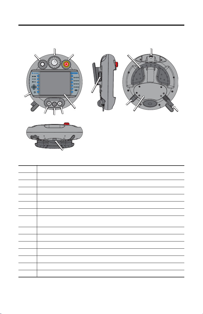
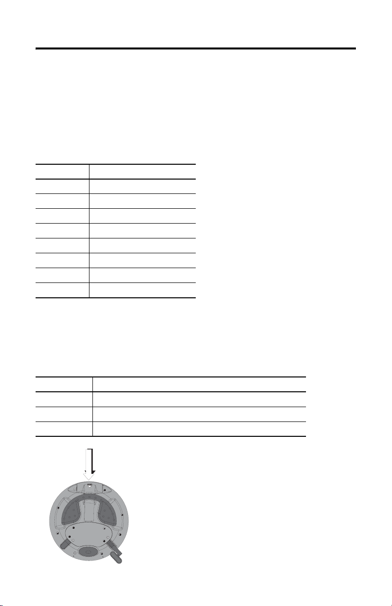
MobileView Guard G750 Description
2
1
3
MobileView Guard G750 5
12
11
4
8
5
1 Potentiometer with 0-127 linear resolution (option)
2 Electronic handwheel, 50 pulses/rev -32768 to +32768 (option)
3 Emergency stop switch, twin-circuit, N/C contacts, 24V dc, 500 mA maximum (option)
4 Membrane keypad with tactile feedback - standard Windows keyboard operation
5 Illuminated momentary push button, normally open, OFF marking, yellow LED (option)
6 3-position key switch (option)
7 Illuminated momentary push button, normally open, ON marking, yellow LED (option)
8 7.7 inch VGA (640 x 480 pixels) passive matrix color LCD display with analog resistive touch
9 3-position, twin circuit, enabling switch (one each side of handle) for safety system interface
10 IrDA keyboard/printer interface, 9600 or 115.2K baud
11 Handle for left or right-hand operation
12 Single slot PC card interface for Type I, II and III cards (option)
13 Strain relief for connection cable (shipped with cable)
14 Back cover to connection compartment
15 Plug for cable outlet when not used (meets degree protection IP54)
screen
7
6
10
9
15
14
13
Publication 2727-QS002E-MU-P
Page 6
6 MobileView Guard G750
Safety Precautions and Elements
This section covers general safety precautions in addition to important information
on the power supply, emergency stop switch, and enabling switches used with the
MobileView Guard G750.
General Safety
It is important to follow the instructions in this document in all circumstances.
Failure to do so could result in potential sources of danger or the defeating of safety
features integrated in the terminal.
In addition to the safety instructions in this document, you must also use safety
precautions and accident prevention measures appropriate to the situation.
ATTENTION
!
• Make sure interrupted processes can be properly restarted
after power failures or power dips. No dangerous
operating conditions must be allowed to occur, even
temporarily.
• In situations where faults occurring within the automation
system could cause personal injury or significant damage
to machinery and equipment, take additional external
safety measures to ensure the system remains in a safe
operating condition.
• Make sure unauthorized persons are not allowed to adjust
settings or make memory modifications that could lead to
dangerous situations.
• Test the functionality of safety-related parts (E-stop and
enabling switches) on a regular basis.
• If the MobileView terminal and controller do not
communicate using a point-to-point connection, keypad
data, for example, may transmit with a delay. Use of an
Ethernet switch between the MobileView terminal and
controller is recommended for a higher speed connection.
• Test safety-relevant parts after strong shocks to the
terminal (for example, if terminal is dropped on ground).
• When the MobileView terminal is used to operate the
machine/plant, ensure that the MobileView is the single
point of operation (C.F. ANSI/RIA 15.06).
• If you use a PC card with the MobileView, always make
sure the PC card is properly loaded. After a strong impact,
the PC card cover remains closed. Verify that card is
properly loaded to maintain a good electrical contact.
• When the MobileView terminal is used in manual mode
(for example, teaching of robot), insure robot moves at a
slower speed (C.F. ANSI/RIA 15.06).
Publication 2727-QS002E-MU-P
Page 7
MobileView Guard G750 7
Handling of MobileView Guard Terminal
Refer to MobileView Guard G750 User Manual for additional handling instructions
to avoid terminal malfunctions or damage.
Power Supply
ATTENTION
!
• The device meets safety class III in accordance with EN
61131-2 and EN 50178. The 24V power supply for the
equipment must provide appropriate isolation between
safety-extra-low-voltage circuits and dangerous-contact
voltage circuits (for example, by safety transformers or
similar facilities).
• Protect the power supply circuit with a 3.15 A fuse.
• The nominal supply voltage of the MobileView terminal
(without Mobile View Connection Cable) is +24V dc
(supply voltage range: 18 to 32V dc).
Typical current consumption is:
- 300 mA at 24V dc
-400 mA at 18V dc
When planning the power supply, consider the voltage
drop on the MobileView Connection Cable.
Specifications of power supply lines in this cable are:
Cross section: AWG24 (0.24 mm
Material: zinc-coated copper strand
Line resistance:
<90 Ohm/km (<145 Ohm/mile)
2
)
Enabling Switches
The electronic enabling switch realizes the enabling equipment as a safety function
for machines in special operating modes. The enabling switch is part of the
MobileView terminal.
Each machine features a normal operating mode and a special operating mode.
• In normal operating mode, guards and/or operative protection devices are
used to prevent access and guarantee safety. Special operating modes are
used to maintain the normal operating mode.
Publication 2727-QS002E-MU-P
Page 8
8 MobileView Guard G750
• In special operating mode, safety must be guaranteed in other ways since the
operator must enter dangerous areas of the machine, and targeted
movements must be possible. In this case, a reduced speed of the machine
must be defined by means of the risk assessment. A movement will only be
possible if an enabling device is actuated. The user must be trained and
must know the details of the intended use. The safety related parts of the
control for reducing speed and for the enabling device must be constructed
so that they meet the safety category according to EN 954-1, defined by the
risk assessment.
To meet safety category 3 in accordance with EN 954-1, the enabling switch must
be implemented with 2 circuits.
EN 60204-1 describes the functioning of the enabling device. Due to the latest
findings of analysis of accidents and since technical solutions are available, the
3-position enabling switch became state of the art. The positions 1 and 3 of the
enabling switch are OFF functions. Only the central position is used for enabling.
The EN 60204-1 is identical with IEC 60204-1. So the 3-position enabling switch is
of international relevance.
The enabling switch consists of a 3-position operating element and separated
evaluation electronics. Essential features are the continuous two-channel circuits
between the actuating elements and the connecting terminals. For the evaluation
circuits, different technologies and circuits are used. Because of the electronic
switching contacts, their lifetime does not depend on the load as long as the
nominal values of the load (ohmic, inductive and capacitive) are not exceeded.
ATTENTION
!
Publication 2727-QS002E-MU-P
• Enabling switches may only be used if the operator
activating the switch recognizes the dangerous situation in
time to take immediate action if necessary.
• The enabling switch is only used to enable commands for
performing dangerous movements. The commands must
be activated by a separate operating element (key on
terminal). Only persons allowed to activate the enabling
switch are allowed to work in the dangerous area.
• On the MobileView Guard terminal, the enabling switches
always feature 2 circuits.
Page 9
MobileView Guard G750 9
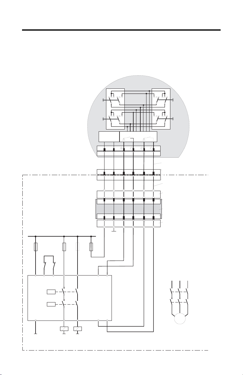
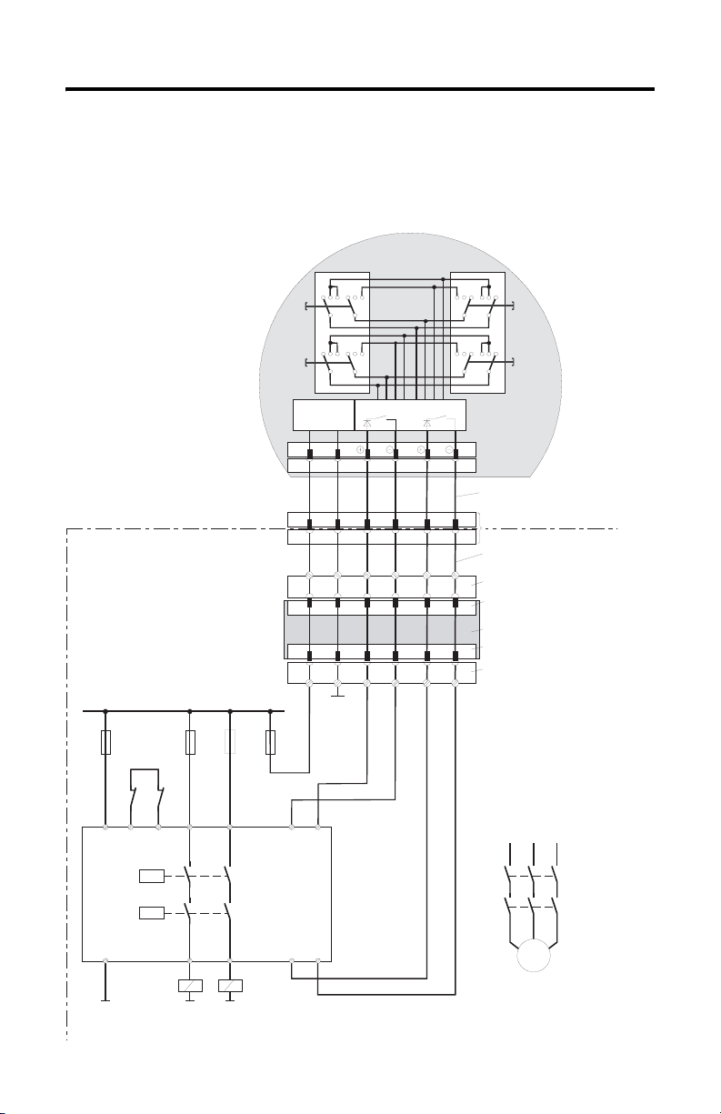
Connection Example with a Safety Control Relay
The diagram below shows suggested wiring for enabling switches using an
PILZ PST safety control relay to meet safety category 3. Refer to PILZ PST
documentation for additional information.
123123 321321
ZT1
L
123123 321321
ZT2
L
MobileView
(2 enabling switches with 3
positions and 2 circuits each)
ZT1
R
ZT2
R
Control cabinet
+24 VDC
F2
F3
4A(t)
F1
1A
Feedback
control lo op
KA KB
X1 X2
A1(+) 23 S11
K1
PILZ
PST1
K2
6A(f)
4A(t)
or
or
6A(f)
13
3,15A
S19:
K3:
K1:
DC/DC
converter
67
67
Evaluation electronics
Circu it 1 Circu it 2
12 34
12 34
7 8 12 17K1: 1 2
7 8 12 1712
ZTxy ....... enabling switch x
Connection cable
MobileView
17-pin coinvers jack
Intermediate cable
y
MobileView
+24V GND ED1+ ED1- ED2+ ED2-
K3:
X1
X2
+24V GND ED1+ ED1- ED2+ ED2-K4:
GND
F4
S12
Terminal block socket K3
on connection box
Male connector X1 on
connection box
Connection box
Male connector X2 on
connection box
Terminal block socket K4 on
connection box
L1 L2 L3
KA
KB
Enabling of
dangerous
movement
A2(-)
14 24 S23 S24
KA KB
GND
GND GND
M
Note: All contacts of KA and KB must be force-guided!
Publication 2727-QS002E-MU-P
Page 10

10 MobileView Guard G750
Switching Element Data
Nominal voltage 24V dc (typical)
Nominal current 500 mA (typical)
Short-circuit current circuit 1; maximum 1.9 A
Max. inductive load (at 500 mA) circuit 1: >1H
Max. capacitive load circuit 1: no limit since the transistor is protected thermally
32V dc (maximum)
circuit 2: maximum 600 mA
circuit 2: maximum 320 mH
circuit 2: maximum 500 µ F
The switching elements of the enabling switches are protected against reversed
polarity. The outputs of both circuits are protected against short circuits and excess
load.
• Circuit 1: thermal protective circuit
• Circuit 2: fold back protective circuit
Foreseeable Misuse of Enabling Switch
Foreseeable misuse means not allowing the enabling switch to be fixed in the
enabling position. The foreseeable misuse of the enabling switch must be restricted.
The following measures are recommended, which cause the machine to stop in
manual mode.
• Inquiry of the enabling switch when turning on the machine/plant and
inquiry of the enabling switch when changing the operating mode from
automatic to manual. (The enabling switch must not be in the enabling
position.)
• The enabling switch must be released within a defined period of time and
pushed into the enabling position again. The length of time must be defined
according to the activity.
Publication 2727-QS002E-MU-P
Page 11
MobileView Guard G750 11
Emergency Stop Switch
The emergency stop switch of the MobileView terminal meets the requirements of
EN 418. It must be designed as an emergency stop of category 0 or category 1 (see
EN 60204-1, chapter 9.2.5.4.2) on the basis of the risk assessment for the machine.
The connection of the positive-break contacts to an appropriate monitoring system
must meet the safety category which is defined by means of the risk assessment (in
accordance with EN954-1) of the machine.
The emergency stop has 2, potential-free, normally closed contacts for connecting
external peripherals, a nominal operating voltage of 24V (Safety Extra Low Voltage
in accordance with EN 61131-2 and EN 50178), and a maximum operating current
of 500 mA.
ATTENTION
!
• When the emergency stop switch is not wired into the
emergency stop circuit, the MobileView terminal must be
stored where it is not available to operators.
Consider that the operator might instinctively activate the
nearest emergency stop in case of danger. This could have
fatal consequences if the emergency stop does not
function.
• Emergency stop functions must remain operational in all
operating modes. Resetting an activated emergency stop
must not result in uncontrolled startup of machines or
installations.
• The emergency stop switch does not replace other safety
devices.
Risk Assessment of Machinery
For the risk assessment, the following standards must be applied:
• EN 292-1 “General principles for design of machinery”
• EN 1050 “Principles for risk assessment of machinery”
• EN 954-1 “Safety-related parts of control systems”
• ANSI/RIA 15.06-1999 “American National Standard for Industrial Robots and
Robot Systems - Safety Requirements (Section 9)”
• ANSI B11.TR3-2000 “Risk Assessment and Risk Reduction - A guide to estimate,
evaluate and reduce risks associated with machine tools”
The safety categories (B, 1, 2, 3, 4) define the structure of safety-related parts of a
machine and are derived from this risk assessment.
Page 9 shows how the enabling function of the MobileView terminal meets safety category 3
using a PILZ PST 1 safety control relay. Please keep in mind, that the entire concept of the
machine must be layed out accordingly.
Publication 2727-QS002E-MU-P
Page 12
12 MobileView Guard G750
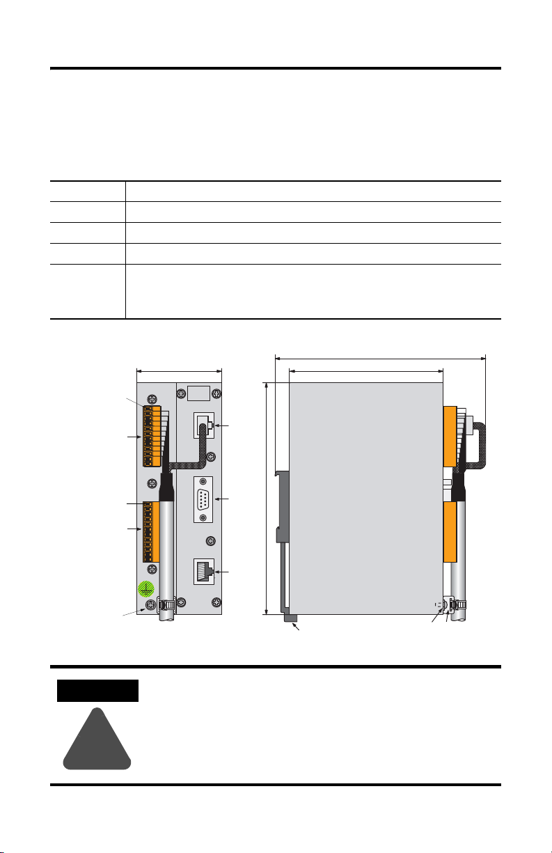
MobileView Junction Box Mounting and Wiring
The MobileView Junction Box (2727-MRJB1) integrates the MobileView terminal
into the control system and is mounted on a DIN rail.
S1 RJ-45 jack for connecting the MobileView data lines.
S2 9-pin DSUB female connector (for future use).
S3 RJ-45 jack to Ethernet network.
X1 12-pin male connector for connecting Junction Box Cable.
X2 12-pin male connector (shipped with female terminal block connector) for connecting the:
Pin 1, 24V dc
X1
(with Female
Terminal Block
Connector K3)
• 24V dc power supply
• emergency stop switch
• enabling switches
60 mm (2.36 in)
24V DC
ON LY
+24V
TERM INAL IN
GND
ES1+
ES1-
ES2+
ES2-
ED1+
ED1-
ED2+
ED2-
RS422 OUT
150 mm (5.91 in)
108 mm (4.25 in
S1
Pin 1, 24V dc
(with Female
Terminal Block
Connector K4)
+24V
GND
ES1+
ES1-
ES2+
X2
ES2-
ED1+
ED1-
ED2+
ED2-
ETHERNET OUT
Grounding
Screw
ATTENTION
The Junction Box and the MobileView terminal meet the safety
class III in accordance with EN 61131-2 and EN 50178.
When connecting the terminal, make sure all voltages
connected to the MobileView terminal are safety extra low
!
voltages by using a safety transformer or a similar facility.
Publication 2727-QS002E-MU-P
S2
162 mm (6.4 in)
S3
DIN Rail Latch
Grounding
Screw
Strain Relief
Page 13
MobileView Guard G750 13
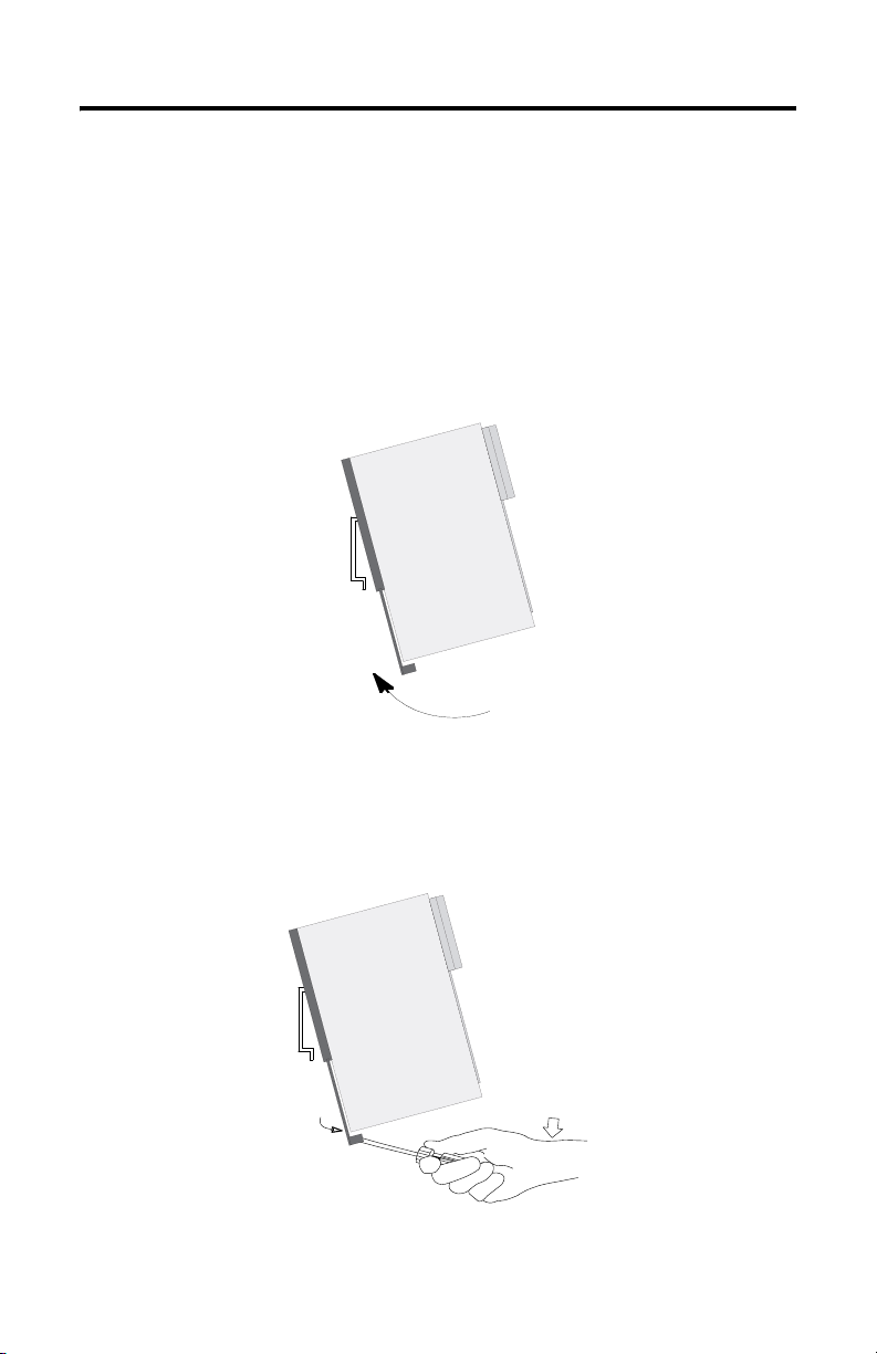
Mounting Junction Box on a DIN Rail
Mount the MobileView Junction Box within an enclosure using a DIN rail.
To install the Junction Box on a DIN rail:
1. Mount the DIN rail.
2. Hook the top slot over the DIN rail.
3. While pressing the Junction Box against the rail, snap the Junction Box into
position.
To remove your Junction Box from the DIN rail:
1. Place a screwdriver in the DIN rail latch at the bottom of the Junction Box.
2. Holding the Junction Box, pry downward on the latch until the Junction Box is
released from the DIN rail.
Publication 2727-QS002E-MU-P
Page 14
14 MobileView Guard G750
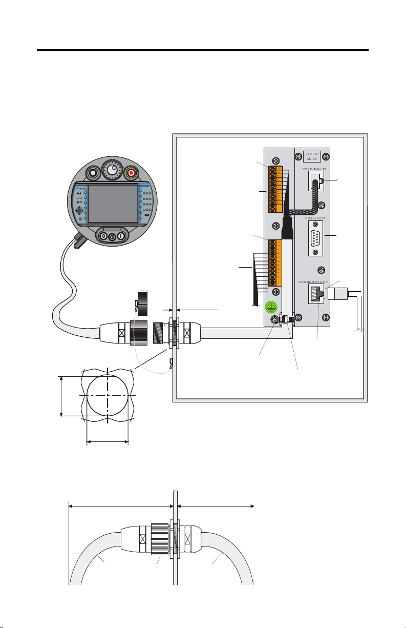
Connecting the MobileView to the Junction Box
The following illustration shows how the MobileView terminal connects to the
Junction Box.
MobileView Terminal
ESC
7 8 9
5 6
4
3
1 2
.
-
0
MobileView
Connection Cable
Connector Cutout
24 mm
(0.94 in)
(1.0 ± 0.0039 in)
25 ± 0.1 mm
n
u
R
KETOP
Dust Cover
Typical Control Cabinet
Pin 1, 24V dc
r
o
r
Er
Terminal Connections
X1/K3
MobileView
Pin 1, 24V dc
X2/K4
Safety Equipment
Connections
maximum wall
thickness 5 mm (0.2 in)
Junction Box
+24V
TERM INAL IN
GND
ES1+
ES1-
ES2+
ES2-
ED1+
ED1-
ED2+
ED2-
+24V
GND
ES1+
ES1-
ES2+
ES2-
ED1+
ED1-
ED2+
ED2-
ETHERNET OUT
24V DC
ON LY
RS 422 OUT
S1
S2
S3
Junction Box Cable
K1
2 m (6.5 ft)
Use Grounding
Screw to Connect
Earth Ground to the
Junction Box
10 Base-T
Connection to
Ethernet Network
Junction Box Cable
Wire Tie
Cable Clearance on Both Sides of Enclosure Wall
130 mm (5.12 in)
Connection
Cable
Publication 2727-QS002E-MU-P
K1
Connection
108 mm (3.94 in)
Junction Box
Cable
Page 15
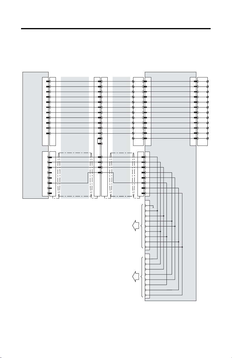
Junction Box Pinout and Wiring
MobileView Guard G750 15
MobileView
S19
S4
Connection Cable
K3
6
7
8
9
10
11
1
2
3
4
5
K2
1
2
3
6
MobileView
pink
black
green-brown
white-green
grey-pink
red-blue
brown
yellow
green
grey
violet
blue
white
orange
red
MobileView
Junction Box Cable
K1
1
2
3
4
5
6
7
8
12
17
11
9
10
13
14
15
16
pink
black
green-brown
white-green
grey-pink
red-blue
brown
yellow
green
grey
violet
blue
white
orange
red
Future Use
To Ethernet Network
K3
X1
1
2
GND_IN
E-Stop, circuit 1, pos.
3
4
E-Stop, circuit 1, neg.
5
E-Stop, circuit 2, pos.
6
E-Stop, circuit 2, neg.
7
Enable sw. circ. 1, pos
8
Enable sw. circ. 1, neg
9
Enable sw. circ. 2, pos
10
Enable sw. circ. 2, neg
11
Not used
12
Not used
K2
S1
1
2
3
4
5
6
7
8
S2
1
2
3
4
5
6
7
8
9
S3
1
TD+
2
TD-
3
RD+
4
5
6
RD-
7
8
Junction Box
24V DC
X2 K4
1
2
3
4
5
6
7
8
9
10
11
12
+24V
GND
ES1+
ES1-
ES2+
ES2ED1+
ED1ED2+
ED2-
Publication 2727-QS002E-MU-P
Page 16
16 MobileView Guard G750
Power Supply Requirements
Electrical Specifications
24V dc Power Supply Use a 24V dc Safety Extra Low Voltage power supply.
Grounding Connect Earth Ground to the Junction Box using the Earth
Supply Voltage Range: 18V dc to 32V dc
Current Consumption: 300mA at 24V dc
Peak Inrush Current: 5.6 A maximum
Ground Screw (shown on page 14).
ATTENTION
!
• The device meets the safety class III in accordance with EN
61131-2 and EN 50178. The 24V power supply for the
equipment must provide appropriate isolation between the
safety-extra-low-voltage circuits and dangerous-contact
voltage circuits (for example, by safety transformers or
similar facilities).
• The power supply circuit must be protected with a 3.15 A
fuse.
• The nominal supply voltage directly of the MobileView
terminal (without the MobileView Connection Cable) is
+24V dc (supply voltage range: 18 to 32V dc).
Typical current consumption is:
- 300 mA at 24V dc
-400 mA at 18V dc
When planning the power supply, take into account the
voltage drop on the Connection Cable.
Specification of power supply lines in this cable:
Cross section: AWG24 (0.24 mm
Material: zinc-coated copper strand
Line resistance: <90 Ohm/km (<145 Ohm/mile)
2
)
Publication 2727-QS002E-MU-P
Page 17
MobileView Guard G750 17
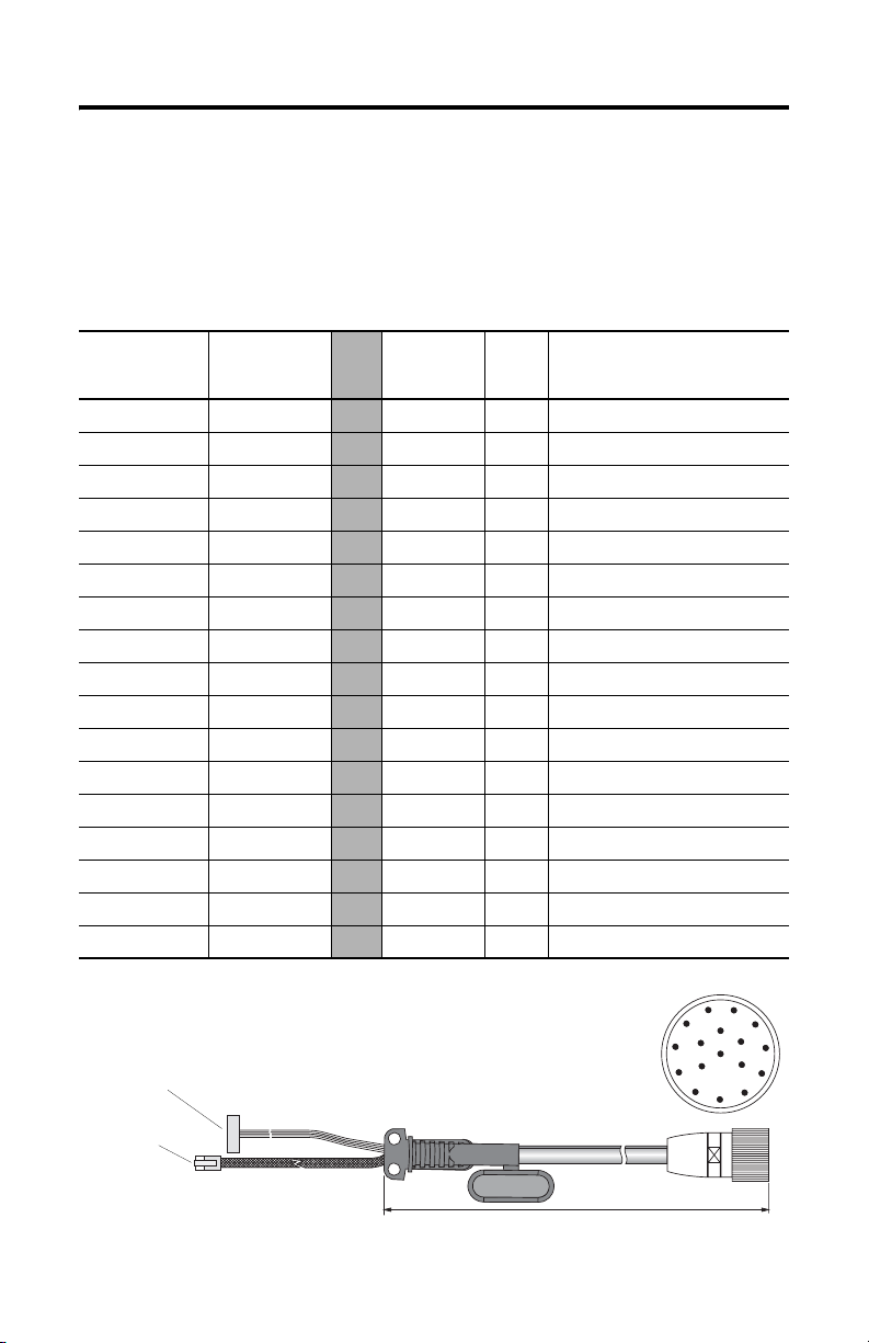
MobileView Connection Cable
The MobileView Connection Cable (2727-MRTxx) connects the MobileView
terminal to the Junction Box Cable. The Connection Cable is 5, 10, 15, or 20 meters
(16.4, 32.8, 49.2, or 65.6 feet). This cable withstands water, cleaning agents, motor
oil, drilling oils, grease, lubricants and condensates containing hydrochloric acid.
K1
17-pin Circular
Connector Pin #
Connection
Cable
Wire Color
1pink
2black
3 green-brown
4 white-green
5grey-pink
6 red-blue
7brown
8yellow
12 green
17 grey
9 bridge to pin 10
10 bridge to pin 9
11 violet
13 blue
14 white
15 orange
16 red
K3, 11-pin
Female
Connector
-->> 6 - 24V DC
-->> 7 - GND_IN
-->> 8 - E-stop, circuit 1, positive
-->> 9 - E-stop, circuit 1, negative
-->> 10 - E-stop, circuit 2, positive
-->> 11 - E-stop, circuit 2, negative
-->> 1 - Enabling switch, circuit 1, positive
-->> 2 - Enabling switch, circuit 1, negative
-->> 3 - Enabling switch, circuit 2, positive
-->> 4 - Enabling switch, circuit 2, negative
-->> - - Not Used
-->> - - Not Used
-->> 5 - Not Used
-->> - 1 TD+ (transmit)
-->> - 2 TD- (transmit)
-->> - 3 RD+ (receive)
-->> - 6 RD- (receive)
K2,
8-pin
RJ-45
Signal
Description
K3, 11-pin
female connector to S19
at MobileView terminal
K2, 8-pin RJ-45
jack to S4 at
MobileView
terminal
K1, 17-pin circular connector
view from connector side
5, 10, 15, or 20 meters (6.4, 32.8, 49.2, or 65.6 feet)
Publication 2727-QS002E-MU-P
11
1
10
9
8
2
12
16
13
17
3
14
15
4
5
7
6
Page 18
18 MobileView Guard G750
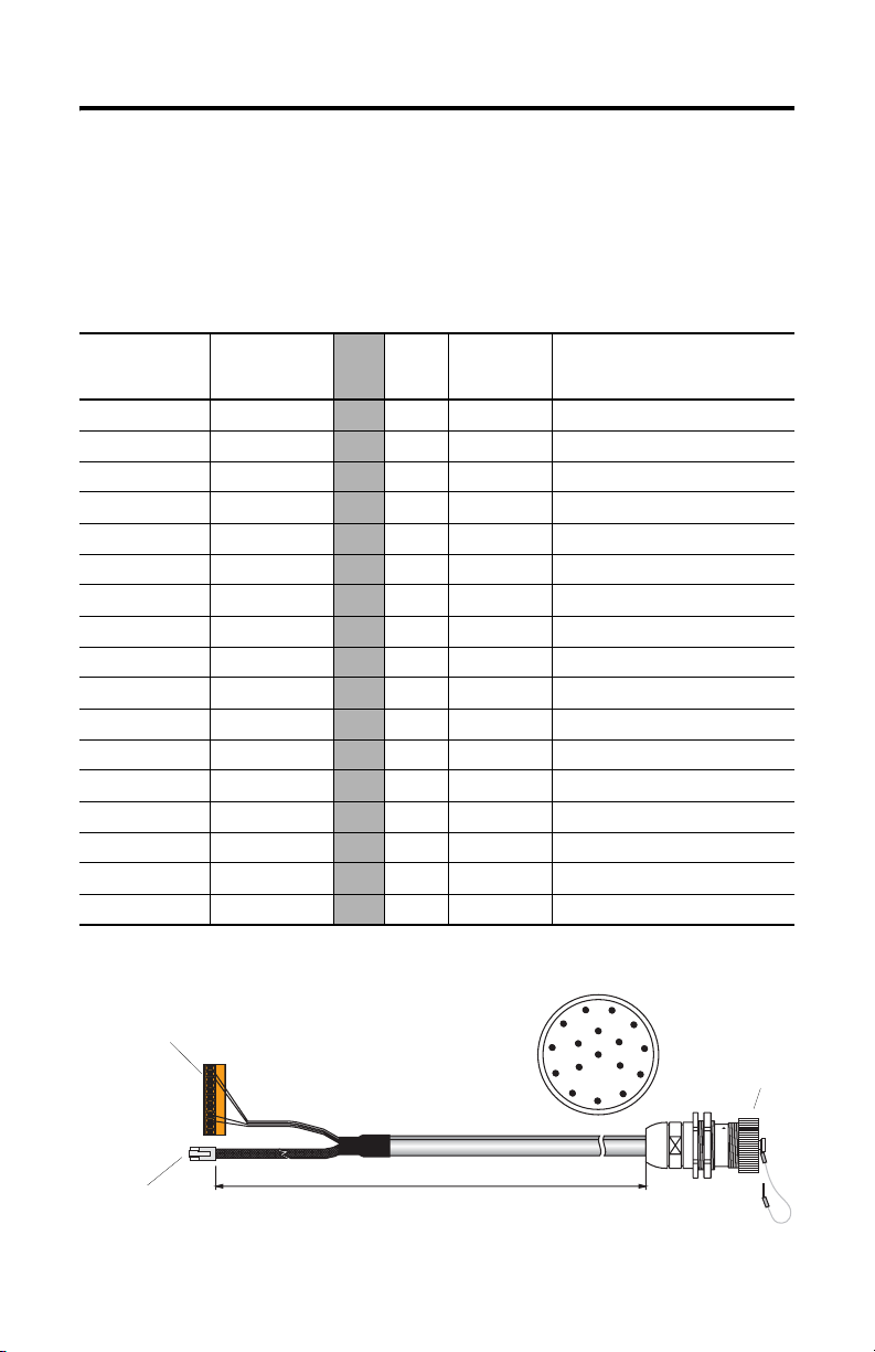
MobileView Junction Box Cable
The MobileView Junction Box Cable (2727-MREX1) connects the Junction Box to
the circular jack in the wall of the enclosure. The cable length is 2 meters (6.5 feet).
When the MobileView terminal is not connected to the Junction box, the dust cover
provides protection for the 17-pin connector.
K1, 17-pin
Circular Jack
Pin #
MobileView
Junction Box
Wire Color
1pink
2black
3 green-brown
4 white-green
5grey-pink
6 red-blue
7brown
8yellow
12 green
17 grey
910 11 violet
13 blue
14 white
15 orange
16 red
K3, 12-pin
connector for
terminal block X1
at Junction Box
K2,
8-Pin
RJ-45
K3, 12-Pin
Ter mi nal
Block
Signal
Description
-->> - 1 24V DC
-->> - 2 GND_IN
-->> - 3 E-stop, circuit 1, positive
-->> - 4 E-stop, circuit 1, negative
-->> - 5 E-stop, circuit 2, positive
-->> - 6 E-stop, circuit 2, negative
-->> - 7 Enabling switch, circuit 1, positive
-->> - 8 Enabling switch, circuit 1, negative
-->> - 9 Enabling switch, circuit 2, positive
-->> - 10 Enabling switch, circuit 2, negative
-->> - - Not Used
-->> - 12 Not Used
-->> - 11 Not Used
-->> 1 - TD+ (transmit)
-->> 2 - TD- (transmit)
-->> 3 - RD+ (receive)
-->> 6 - RD- (receive)
K1, 17-pin circular jack
view from connector side
1
11
2
12
10
16
13
3
14
4
5
9
17
15
8
7
6
Dust Cover
K2, 8-pin RJ-45
jack (Ethernet) for
S1 at Junction Box
Publication 2727-QS002E-MU-P
2 meter (6.5 ft)
K1, 17-pin circular jack
mounts to enclosure
Page 19
MobileView Guard G750 19
MobileView Terminal
This section provides details on:
• How to remove the back cover of the MobileView terminal
• Ethernet connection
• Using the PC Card slot
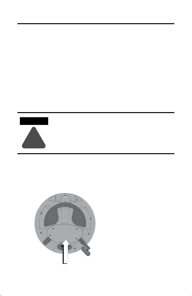
Removing the Back Cover
This section shows how to remove the back cover of the MobileView terminal.
Once the back cover is removed you have access to the area which contains all of
the connectors.
ATTENTION
Turn off the power supply before removing the back cover of
the MobileView terminal.
When the back cover is removed, the MobileView terminal is
sensitive to electrostatic discharge.
!
1. Place the terminal on a stable, flat surface.
2. Remove the 6 screws that secure the back cover to the terminal.
3. Carefully lift off the back cover and set aside.
Back Cover
Publication 2727-QS002E-MU-P
Page 20
20 MobileView Guard G750
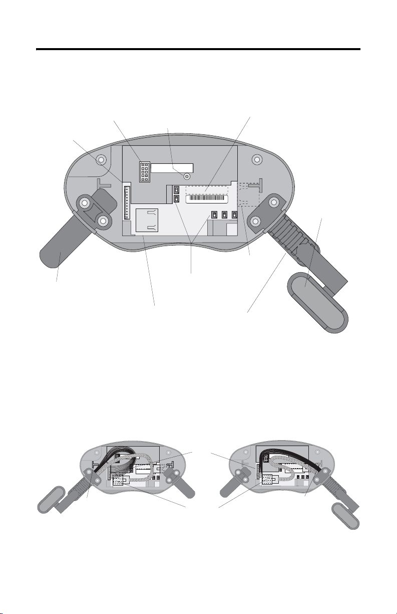
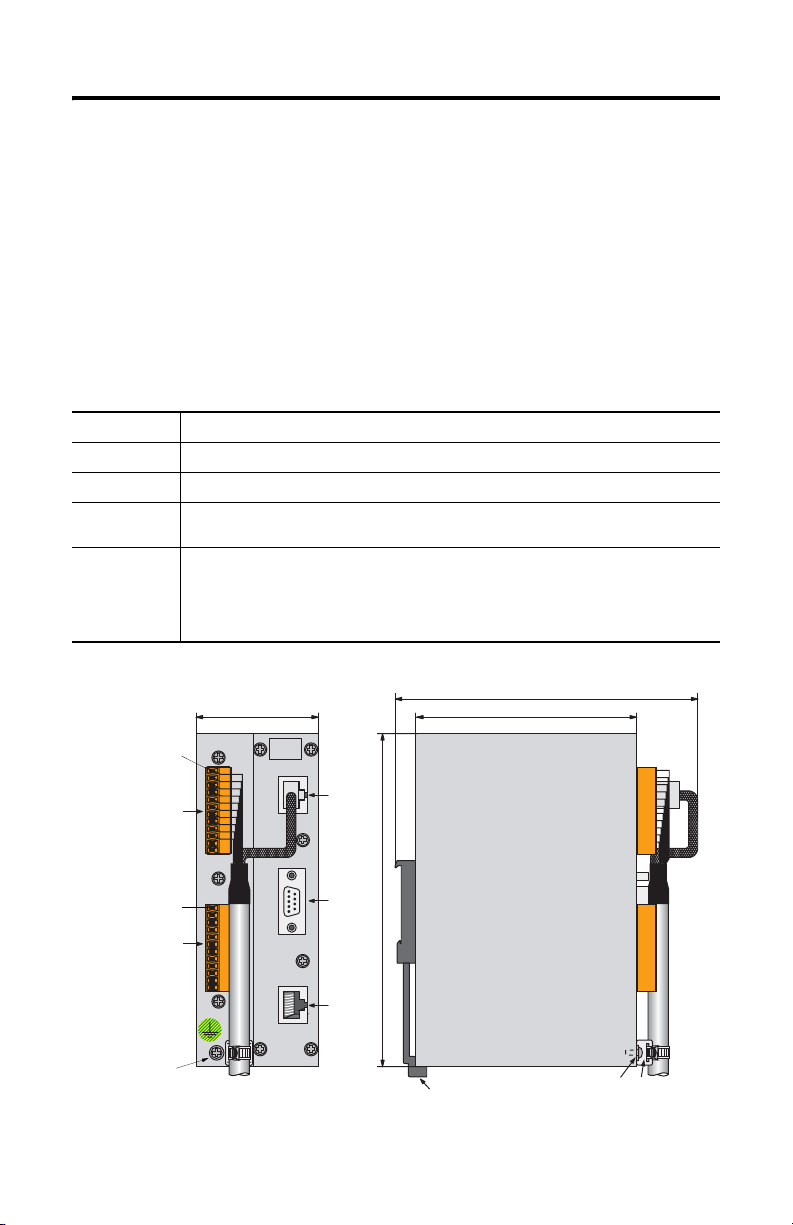
The following illustration shows what the connection area of the MobileView
terminal looks like with the back cover removed.
RS-232 Port
for downloading software.
Main connector (S19)
for power supply and
control lines
Important: Install plug on
unused MobileView
Connection Cable outlet.
Reset Button
for rebooting Windows CE.
All data not flushed to Registry or
saved to Flash Storage is lost.
pin 1
Serial
port
S19
Reset
B5
B4
00:60:B5:06:00:01
S4
Ethernet
Position of switches does not
affect terminal operation (for
future use)
Ethernet connector (S4)
for data exchange
Ethernet Label
Ethernet (Mac) Address
2250-00001
AABBCCDDEEFF
B2 B6 B3
S6,
COM -Modul
Connector (not used)
Strain Relief
for connecting MobileView
Connection Cable (on left or right side)
Cable Tag
Allows the terminal to
be uniquely identified.
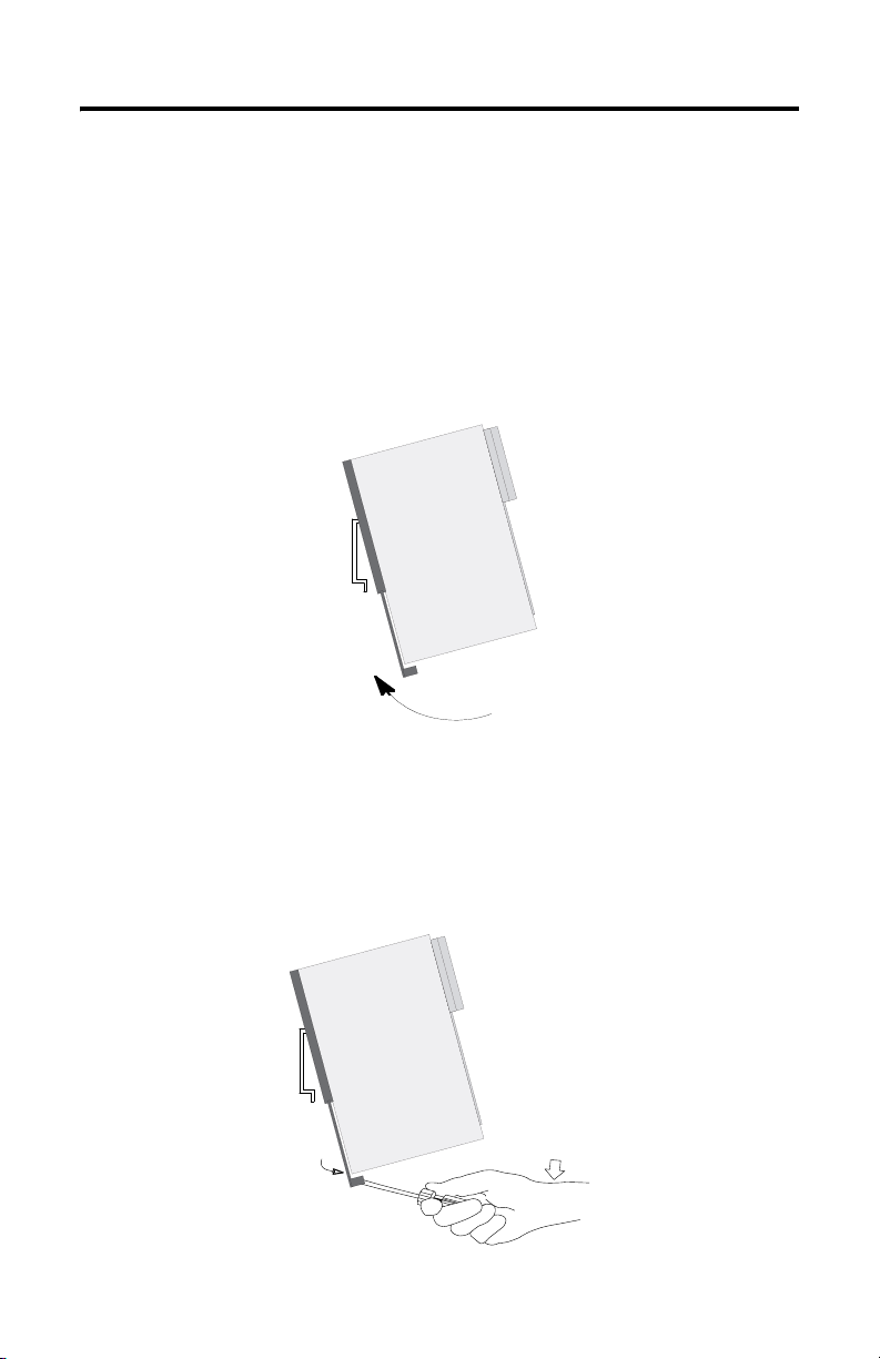
Relocating MobileView Connection Cable
The MobileView Connection Cable can be attached on the right or left side of the
terminal for right or left-hand operation. To relocate the cable, simply grasp the
strain relief and/or the plug and slide off of mount with a rocking motion.
Attaching Cable on Right
S19
Main
S6,
Connector
COM -Modul
Avoid routing cable
over T-support.
S4, Ethernet Connector
Important: Make sure the K3, 11-pin female connector clicks completely into S19, Main Connector when
plugged in. Ensure proper seating of K2, 8-pin RJ-45 jack into S4, Ethernet Connector. Avoid routing the
cable over the T-supports. After routing the cable, secure the back cover to the terminal with the 6 screws.
Tighten screws to a torque of 4.42 In-lbs to maintain IP54 degree protection.
Publication 2727-QS002E-MU-P
Attaching Cable on Left
Avoid routing cable
over T-support.
S6,
COM-Modul
Page 21
MobileView Guard G750 21
Ethernet Connection
The MobileView terminal is equipped with a 10Base-T interface which supports
TCP/IP protocol at 10MBaud for half-duplex communications.
The Ethernet connector at S3 on the Junction Box provides a connection to an
Ethernet network. The connector uses an 8-pin modular jack connector. Pinouts are
as follows:
Pin # Ethernet Signal
1TD+
2TD-
3RD+
4 Not Used
5 Not Used
6RD-
7 Not Used
8 Not Used
Using the PC Card Slot
The PC card slot is a factory installed option and supports Type I, II, and III PC
cards. The following PC cards are available from Allen-Bradley. The terminal does
not support SRAM cards, Cardbus cards, or cards that use 12 volts for programming.
Catalog No. Description
2711-NM28 8M flash ATA card for storing applications.
2711-NM216 16M flash ATA card for storing applications.
2711-NM232 32M flash ATA card for storing applications.
PC Card
Compartment
Publication 2727-QS002E-MU-P
Page 22
22 MobileView Guard G750
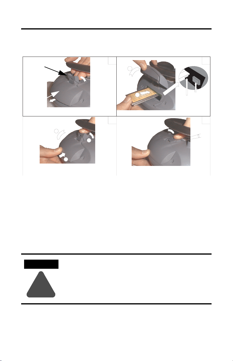
Inserting the PC Card
Locking Lever
PC Card Cover
a
c
b
1
a
b
3
1. Unlocking PC card cover (see illustration 1).
a. Lay the MobileView with the display facing down onto a flat, clean table
(preferably on ESP pad). Take care not to damage the terminal and its
elements.
b. Lift up on locking lever until PC Card Cover is released.
2. Inserting PC card (see illustration 2).
a. Lift the cover up.
b. Insert the PC card until it locks in and the ejection button pops out.
2
Ejection button
4
Must snap
completely.
ATTENTION
Verify that the corner of the PC card (with the notch) is
inserted into the slot on the side of the ejection button.
Check the condition and position of the cover seal before
closing the PC card cover.
!
3. Close and lock the cover (see illustration 3).
4. Press the cover down until it snaps in completely (see illustration 4).
Publication 2727-QS002E-MU-P
Page 23

MobileView Guard G750 23
Removing the PC Card
1
1
3
2
1. Open the PC card cover. Refer to Inserting the PC Card on page 22 for procedures.
2. Press the ejection button on the PC card slot.
3. Remove the PC Card.
4. Close and lock the cover.
5. Press the cover down until it snaps in completely.
Publication 2727-QS002E-MU-P
Page 24
24 MobileView Guard G750
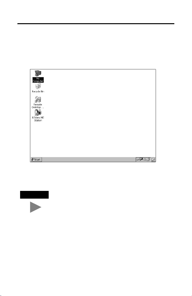
Startup/Power On
1. Attach the MobileView Connection Cable to the Junction Box Cable as
shown on page 14. Tighten threaded coupling until it is finger tight.
2. Check the MobileView terminal for a start-up screen.
If the start-up screen does not appear, check the 24V dc power source and
cable connections at the Junction Box and MobileView terminal.
TIP
Publication 2727-QS002E-MU-P
An icon for RSView ME software appears on the MobileView
2727-G7P20D1Q6 and 2727-G7P20D3Q7 start-up screens only.
Page 25
MobileView Guard G750 25
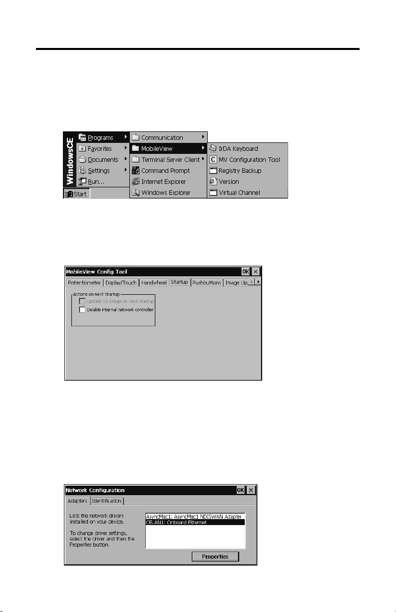
Hardware Configuration
1. From the task bar, select Start>Programs>MobileView>MV
Configuration Tool.
The Config Tool dialog opens with the default tab selected. Adjust display
touch screen and device settings, as desired. Refer to publication
2727-UM002, MobileView Guard G750 User Manual for details.
Ethernet Network Configuration
To configure the onboard Ethernet communications hardware of your
MobileView terminal:
1. Tap the Start button and select Settings>Control Panel.
2. Double-tap the Network icon.
Publication 2727-QS002E-MU-P
Page 26
26 MobileView Guard G750
3. Tap the Adapters tab in the Network Configuration dialog.
4. Select the CELAN1:Onboard Ethernet from the list of drivers, then tap the
Properties button.
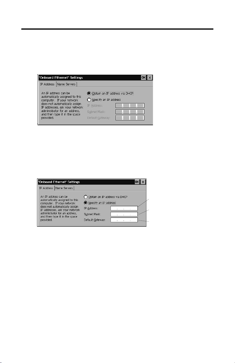
5. Tap the IP Address tab and select either Obtain an IP Address via DHCP
or Specify an IP Address, depending on your network configuration. If you
select Specify an IP Address, complete the 3 text boxes with information
from your network administrator or ISP. Use the on-screen input panel to
enter the text. You can access the input panel by tapping the Stylus icon on
the task bar.
IP Address must be a unique
address on the LAN.
Subnet Mask must be identical
to the server subnet mask.
Default Gateway is optional.
6. Tap OK in the settings dialog. A notification window appears prompting you
to either remove and reinstall your card or restart the device for the new
settings to take effect. Tap the OK button in notification window.
7. Tap OK on the Network Configuration dialog and close the Control Panel.
Publication 2727-QS002E-MU-P
Page 27
Saving Registry Settings
MobileView Guard G750 27
ATTENTION
Any hardware configuration or Ethernet network configuration
changes must be saved to the registry or they will be lost during a
MobileView terminal power cycle.
!
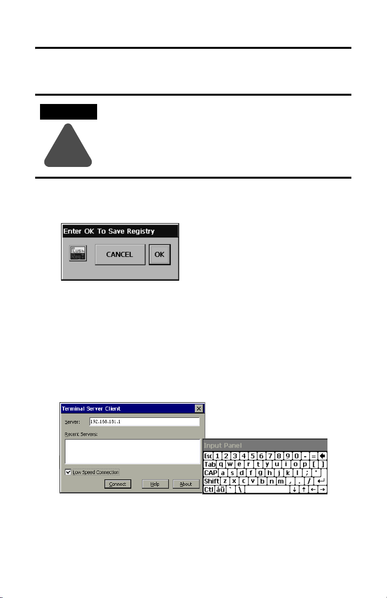
To save the current registry settings:
1. Tap the Start button and select Programs>MobileView>Registry Backup.
2. To save the registry, tap the OK button. Saving the registry may take up to
15 seconds. The registry backup will automatically close.
Starting Terminal Services
To connect to a terminal server as a CE client:
1. Double-tap the Terminal Server Client shortcut on the desktop of the
MobileView terminal or select the Terminal Server Client application from
the Programs>Terminal Server Client folder on the Start menu.
2. Enter the Terminal Server’s Name or a valid TCP/IP address in the Server
box using the on-screen input panel or select a server name or address from
the Recent Servers box.
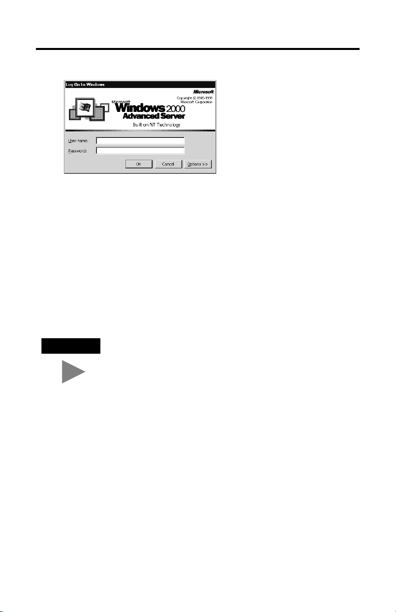
3. Tap the Connect button. A server log on window similar to the one below
appears.
Publication 2727-QS002E-MU-P
Page 28
28 MobileView Guard G750
4. Enter your user name and password to operate as an active CE client.
Shutdown/Power Off
1. Close down all applications that are running on CE client.
2. Tap the Start button on the CE client task bar. Select Shutdown and then
Log Off to disconnect from the terminal server.
3. Remove 24V dc power from the MobileView junction box or disconnect the
MobileView connection cable from the junction box cable.
TIP
Publication 2727-QS002E-MU-P
Time/Date/Regional Setting information is not saved during a
reboot.
Page 29
MobileView Guard G750 29
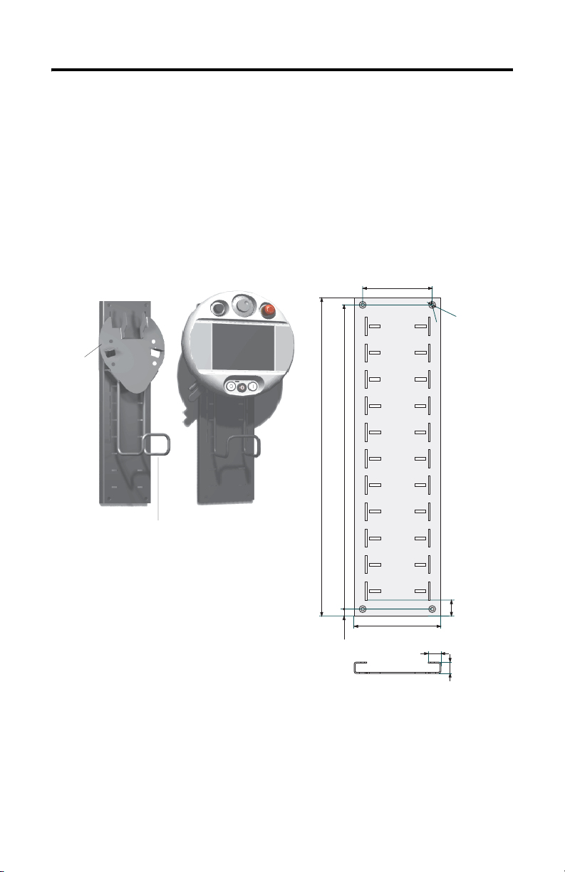
Mounting Bracket Installation
The MobileView Mounting Bracket (catalog number 2727-MRMB1) is used for
stationary operation or storage of the terminal. The following illustration shows the
mounting bracket with and without the terminal mounted.
The carrier is adjustable in 8 positions over a height of 320 mm (12.6 in). It is
important to attach the carrier at all 4 points on the height adjustment plate. Mount
the cable holder on the carrier using the screws delivered with the bracket.
Height Adjustment Plate
Carrier
Connection Cable Holder
Plate Dimensions and Mounting Holes
550 mm (21.65 in)
MobileView
120 mm (4.72 in)
526 mm (20.71 in)
150 mm (5.91 in)
22 mm (0.87 in)
12 mm (0.47 mm)
Use suitable screws (not shipped with product) to mount the plate.
6
m
m
1
d
2
i
a
.
(
0
m
.
2
4
.
(
0
.
4
7
i
n
28 mm
)
20 mm
(1.1 in)
(0.79 in)
i
n
)
m
d
i
a
Publication 2727-QS002E-MU-P
Page 30

30 MobileView Guard G750
European Communities (EC) Directive Compliance
The product has a CE mark and is approved for installation within the European
Union and EEA regions. It has been designed and tested to meet the following
directives.
EMC Directive
This product is tested to meet the Council Directive 89/336/EC Electromagnetic
Compatibility (EMC) by applying the following standards, in whole or in part,
documented in a technical construction file:
• EN 61000-6-4:2001 EMC - Generic Standard - Emission Standard for Industrial
Environments
• EN 61000-6-2:2001 EMC - Generic Standard - Immunity for Indutrial
Environments
• EN 61131-2:1994 - Programmable Controllers Part 2 - Equipment
Requirement and Tests
This product is intended for use in an industrial environment.
Machinery Directive
The MobileView Guard G750 is tested to meet the Council Directive 98/37/EC,
Safety of Machinery, by applying the following standards:
• EN 954-1:1996 Safety-related parts of control systems
• EN 292-1:1991 - Basic concepts, general principles for design
• EN 292-2:1991 + A1:1995 - Technical principles and specifications
• EN 418:1992 - Emergency stop equipment, function aspects, principles of design
• EN 60204-1:1997 - Electrical equipment of machines, general requirements
A Declaration of Conformity is available upon request.
Publication 2727-QS002E-MU-P
Page 31

MobileView Guard G750 31
Standards and Agency Certifications
General
UL 508 Industrial Control Equipment
CSA C22.2 No. 14 Industrial Control Equipment
C-Tick Marked for all applicable acts
Electromagnetic Compatibility (EMC)
EN 61000-6-4:2001 EMC - generic emission standard for industrial environment
EN 61000-6-2:2001 EMC - generic immunity standard for industrial environment
IEC 61131-2 final draft chapt 7+8 Programmable Controllers - Equipment requirements and test
Operating Safety
IEC 61131-2, EN 61131-2:1994 +
A11:1996 + A12:2000
IEC 60204-1, EN 60204-1:1997 Safety of machinery - electrical equipment of machines, general
EN 50178:1997 Electronic equipment for use in power installations
Machinery Standards
EN 614-1:1995 Ergonomic design principles
EN 894-1:1997, -2, -3 Ergonomic requirements for the design of displays and control actuators
ISO 13849-1:1999, EN 954-1:1996 Safety-related parts of control systems
ISO DIS 12100-1, EN 292-1:1991 Basic concepts, general principles of design
ISO DIS 12100-2,
EN 292-2:1991 + A1:1995
ISO 13850:1996, EN 418:1992 Emergency stop equipment, functional aspects, principles for design
EN 60204-1: 1997 Safety of machinery - electrical equipment of machines, general
Programmable Controllers - Equipment requirements and test
requirements
Technical principles and specifications
requirements
Standards for MobileView used in Robot Systems
EN 775:1992 Industrial robots
ANSI/RIA R15.06 - 1999 American National Standard for Industrial Robots and Robot Systems -
ANSI/RIA R15.02/1 American National Standard for Industrial Robots and Robot Systems -
UL 1740 Robots and Robot Equipment
Standards for MobileView used in Machining Centers
ISO 11161 Industrial Automation Systems - Safety of Integrated Manufacturing
EN 12417:2001 Machine tools - Safety - Machining Centers
safety requirements
Hand-Held robot Control Pendants - Human Engineering Design Criteria
Systems
Publication 2727-QS002E-MU-P
Page 32

32 MobileView Guard G750
MobileView Guard G750 Configurations
Features 2727-G7P20D1P4 2727-G7P20D1P5 2727-G7P20D1Q6 2727-G7P20D3Q7
7.7 Inch VGA Display Yes
IrDA Interface Yes
3-Position Enable Switch Yes
2-Circuit E-Stop- Position 3 No Yes
Memory 16MB DRAM/32MB Flash 64MB DRAM/64MB Flash
PC Card Slot No Yes
Communications 10Base-T Ethernet
Push Button with
OFF Marking Position 5
Key Switch Position 6
Operating Elements No No
Windows CE OS Yes
RSView Machine Edition No Yes
Thin Client Application Yes
Push Button with
ON marking Position 7
Potentiometer Position 1
Electronic
Handwheel
-Position 2
No
Accessories
Catalog Number Description
2727-MRT5 MobileView Guard Connection Cable (5 meter /16.4 ft) - connects Guard terminal to the
2727-MRT10 MobileView Guard Connection Cable (10 meter /32.8 ft) - connects Guard terminal to the
2727-MRT15 MobileView Guard Connection Cable (15 meter /49.2 ft) - connects Guard terminal to the
2727-MRT20 MobileView Guard Connection Cable (20 meter/65.6 ft) - connects Guard terminal to the
2727-MRJB1 MobileView Guard Junction Box - provides controller, Ethernet, power supply, emergency
2727-MREX1 MobileView Guard Junction Box Cable (2 meter / 6.5 ft) - connects the MobileView Guard
2727-MRC1 MobileView Guard Download Cable (4 meter /13.1 ft) - connects between the MobileView
2727-MRMB1 MobileView Guard Mounting Bracket for stationary operation or storing the MobileView
2727-MRSDK1 MobileView Guard SDK file set for Windows CE development
Publication 2727-QS002E-MU-P
Junction Box cable.
Junction Box cable.
Junction Box cable.
Junction Box cable.
stop switch, and enabling switch connections.
Connection Cable to the Junction Box.
Guard terminal to a PC.
Guard terminal.
Page 33

MobileView Guard G750 33
Specifications
General
Processor Intel StrongARM SA-1110/206 MHz
Operating System
2727-G7P20D1P4, -G7P20D1P5
2727-G7P20D1Q6, -G7P20D3Q7
Memory 2 sizes: 16M DRAM/32M Flash or
Display Passive LCD 7.0-inch VGA with 256 colors
Touch Screen 7.7-inch analog resistive
Keypad Stainless steel dome membrane switches with tactile
Housing Twin shell
Dimensions
Diameter
Depth without handle
Depth with handle
Weight 1550 grams (3.42 lbs) - without options
Microsoft Windows CE 3.0
Microsoft Windows CE 4.1
64M DRAM/64M Flash
feedback
Resistive to grease, oil, lubricants, alcohol
Silicone-free
Flammability class: UL 94-V0
290 mm (11.42 inches)
80 mm (3.15 inches)
130 mm (5.12 inches)
Electrical
Nominal Supply Voltage 24V dc safety-extra-low-voltage
Supply Voltage Range 18V dc to 32V dc
Input Current 300mA maximum
Peak Inrush Current 5.6A maximum
Power Supply 10 ms minimum holdup time (EN 61131-2:1994 and
Environmental
Operating Temperature
Storage Temperature
Relative Humidity (non-condensing)
Protection Degree IP54
Vibration (operating) 10 Hz <
Shock (operating) 25 G / 11 ms IEC 60068-2-27
EN 50178:1997)
° to 50°C (32° to 122°F)
0
-25
° to +70°C (-13° to +158°F)
5 to 95% at 0 to 50
f < 57 Hz with 0.15 mm (0.0059 in)
f < 150 Hz with 2 g (0.0044 lb)
57 Hz <
°C (32° to 122°F)
Publication 2727-QS002E-MU-P
Page 34

34 MobileView Guard G750
Publication 2727-QS002E-MU-P
Page 35

Guide de mise en route
MobileView Guard G750
(Références 2727-G7P20D1P4, 2727-G7P20D1P5, 2727-G7P20D1Q6, 2727-G7P20D3Q7)
Français
Pour des informations plus détaillées sur le MobileView Guard G750, consultez la
publication 2727-UM002.
Vous pouvez télécharger une version électronique gratuite de la
publication 2727-UM002 à partir :
• du CD d’installation ;
• www.support.rockwellautomation.com
www.theautomationbookstore.com
Sommaire . . .
Informations importantes destinées à l’utilisateur ......................................................... 36
Description du MobileView Guard G750 ......................................................................... 37
Consignes de sécurité ...................................................................................................... 38
Montage et câblage du boîtier de raccordement MobileView ....................................... 45
Démontage du capot arrière ............................................................................................ 53
Connexion Ethernet .......................................................................................................... 55
Utilisation du logement pour carte PC ............................................................................. 55
Démarrage/Mise sous tension ........................................................................................ 58
Configuration matérielle .................................................................................................. 58
Configuration du réseau Ethernet .................................................................................... 59
Enregistrement des paramètres de la base de registres ................................................ 60
Démarrage des services Terminal Server ........................................................................ 61
Arrêt/Mise hors tension .................................................................................................. 62
Installation du support de fixation ................................................................................... 63
Conformité aux directives européennes (CE) ................................................................... 64
Normes et certifications .................................................................................................. 65
Configurations du MobileViewGuard G750 .................................................................... 67
Accessoires ...................................................................................................................... 67
Spécifications .................................................................................................................. 68
Publication 2727-QS002E-MU-P
Page 36

36 MobileView Guard G750
Informations importantes destinées à l’utilisateur
En raison de la diversité des utilisations des produits décrits dans la présente
publication, les personnes qui en sont responsables doivent s’assurer que toutes les
mesures nécessaires ont été prises pour que l’application et l’utilisation des produits
soient conformes aux exigences de performance et de sécurité, ainsi qu’aux lois,
règlements, codes et normes en vigueur.
Les illustrations, schémas et exemples de programmes contenus dans ce manuel
sont présentés à titre indicatif uniquement. En raison du nombre important de
variables et d’impératifs associés à chaque installation, la société Allen-Bradley ne
saurait être tenue pour responsable ni être redevable (y compris en matière de
propriété intellectuelle) des suites d’utilisation réelle basée sur les exemples et
schémas présentés dans cette publication.
La publication Allen-Bradley SGI-1.1, « Safety Guidelines for the Application,
Installation and Maintenance of Solid-State Control » (disponible auprès de votre
agence commerciale Allen-Bradley), décrit certaines différences importantes entre
les équipements électroniques et les équipements électromécaniques, qui devront
être prises en compte lors de l’application de ces produits, comme indiqué dans la
présente publication.
Toute reproduction totale ou partielle de la présente publication sans autorisation
écrite de la société Rockwell Automation est interdite.
Des remarques sont utilisées tout au long de ce manuel pour attirer votre attention
sur les mesures de sécurité à prendre en compte :
ATTENTION
Actions ou situations risquant d’entraîner des blessures
pouvant être mortelles, des dégâts matériels ou des pertes
financières.
!
Les mises en garde « Attention » vous aident à :
• identifier un danger ;
• éviter ce danger ;
• en discerner les conséquences.
IMPORTANT
Allen-Bradley est une marque commerciale de Rockwell Automation.
Publication 2727-QS002E-MU-P
Informations particulièrement importantes dans le cadre de
l’utilisation du produit.
Page 37

Description du MobileView Guard G750
2
1
3
MobileView Guard G750 37
12
11
4
8
5
1 Potentiomètre avec résolution linéaire de 0 à 127 (option)
2 Volant de manœuvre électronique, 50 impulsions/tour de -32768 à +32768 (option)
3 Interrupteur d’arrêt d’urgence, circuit jumelé, contacts N.F., 24 V c.c., 500 mA maximum (option)
4 Clavier tactile - Fonctionnalités Windows standard
5 Bouton-poussoir lumineux à impulsion, normalement ouvert, marquage désactivé, voyant jaune
6 Commutateur à clé à 3 positions (option)
7 Bouton-poussoir lumineux à impulsion, normalement ouvert, marquage activé, voyant jaune
8 Ecran LCD couleur à matrice passive VGA 7,7 pouces (640 x 480 pixels) avec dalle tactile
9 Commutateurs d’activation, circuit jumelé, à 3 positions (un de chaque côté de la poignée) pour
10 Interface IrDA imprimante/clavier, 9600 ou 115,2 Kbauds
11 Poignée pour gaucher ou pour droitier
12 Interface de carte PC à un logement pour cartes de type I, II et III (option)
13 Languette de réduction de tension pour câble de raccordement (livrée avec le câble)
14 Capot arrière du compartiment de raccordement
15 Obturateur pour la prise de câble non utilisée (degré de protection IP54)
(option)
(option)
analogique résistive
l’interface système de sécurité
7
6
10
9
15
14
13
Publication 2727-QS002E-MU-P
Page 38

38 MobileView Guard G750
Consignes de sécurité
Cette section présente les consignes générales de sécurité, ainsi que des
informations importantes sur l’alimentation, le bouton-poussoir d’arrêt d’urgence et
les commutateurs d’activation utilisés avec le MobileView Guard G750.
Sécurité générale
Il est important de se conformer aux instructions de ce document en toutes
circonstances. Le non-respect de ces instructions peut entraîner des dangers ou
rendre les fonctions de sécurité intégrées au terminal inopérantes.
Outre les instructions de sécurité indiquées dans ce document, vous devez
également suivre les précautions de sécurité et les mesures de prévention
d’accidents qui conviennent à la situation.
Publication 2727-QS002E-MU-P
Page 39

MobileView Guard G750 39
ATTENTION
!
• Veillez à ce que les procédures interrompues puissent être
redémarrées après des coupures d’alimentation ou des
microcoupures. N’utilisez jamais le matériel dans des
conditions dangereuses, même brièvement.
• Dans les cas où des pannes survenues au sein du système
d’automatisation pourraient provoquer des blessures
corporelles ou des dégâts importants aux machines et à
l’équipement, prenez des mesures de sécurité
supplémentaires pour préserver un fonctionnement sans
risque du système.
• Veillez à ce que les personnes non autorisées ne puissent
pas régler les paramètres ni effectuer des modifications de
mémoire qui pourraient entraîner des situations
dangereuses.
• Testez régulièrement les fonctionnalités des composants de
sécurité (bouton-poussoir d’arrêt d’urgence et
commutateurs d’activation).
• Si le terminal MobileView et l’automate ne communiquent
pas par une connexion point-à-point, il est possible que
les données du pavé numérique, par exemple, soient
transmises avec du retard. Il est recommandé d’utiliser un
commutateur Ethernet entre le terminal MobileView et
l’automate pour augmenter la vitesse de connexion.
• Testez les composants de sécurité si le terminal a subi des
chocs importants (s’il est tombé à terre par exemple).
• Lorsque le terminal MobileView est utilisé pour faire
fonctionner une machine ou une unité de production,
veillez à ce qu’il soit le seul et unique point de
fonctionnement (cf. ANSI/RIA 15.06).
• Si vous utilisez une carte PC avec le MobileView, veillez
toujours à ce que cette carte soit correctement insérée.
Après un choc violent, vérifiez que le volet du logement
pour carte PC est bien fermé et que la carte est
correctement insérée afin de maintenir un bon contact
électrique.
• Lorsque le terminal MobileView est utilisé en mode
manuel (pour des instructions sur un robot par exemple),
définissez une vitesse plus lente pour les mouvements du
robot (cf. ANSI/RIA 15.06).
Publication 2727-QS002E-MU-P
Page 40

40 MobileView Guard G750
Manipulation d’un terminal MobileView Guard
Pour de plus amples informations sur la manipulation d’un
MobileView Guard G750, consultez son manuel utilisateur afin d’éviter tout
dommage ou dysfonctionnement du terminal.
Alimentation
ATTENTION
!
• Cet appareil est conforme à la classe de sécurité III, selon
les normes EN 61131-2 et EN 50178. L’alimentation 24 V
destinée à l’équipement doit fournir une isolation
appropriée entre les circuits haute sécurité et les circuits à
tensions dangereuses (les transformateurs de sécurité par
exemple).
• Protégez le circuit d’alimentation par un fusible de 3,15 A.
• La tension d’alimentation nominale du terminal
MobileView (sans le câble de raccordement) est de
+24 V c.c. (plage de tensions de l’alimentation : de 18 à
32 V c.c.).
La consommation est généralement la suivante :
-300 mA à 24 V c.c.
-400 mA à 18 V c.c.
Lors de la planification de l’alimentation, tenez compte de
la chute de tension du câble de raccordement MobileView.
Caractéristiques des fils d’alimentation de ce câble :
Diamètre : 0,24 mm
Matériau : fil de cuivre galvanisé
Résistance de ligne :
2
(calibre 24)
< 90 ohms/km
Commutateurs d’activation
Le commutateur d’activation électronique considère le dispositif d’activation comme
une fonction de sécurité pour les machines ayant des modes de fonctionnement
particuliers. Le commutateur d’activation est intégré au terminal MobileView.
Chaque machine comprend un mode de fonctionnement normal et un mode de
fonctionnement spécial.
• En mode de fonctionnement normal, les protections et/ou les dispositifs de
protection des opérations servent à empêcher l’accès et à garantir la sécurité.
Les modes de fonctionnement spéciaux sont utilisés pour maintenir le mode
de fonctionnement normal.
Publication 2727-QS002E-MU-P
Page 41

MobileView Guard G750 41
• En mode de fonctionnement spécial, la sécurité doit être assurée
différemment, l’opérateur devant accéder à des zones dangereuses : des
mouvements ciblés doivent donc être possibles. Dans ce cas, la vitesse de la
machine doit être réduite en fonction des risques évalués et tout mouvement
commandé uniquement par un dispositif d’activation. L’utilisateur doit être
formé et connaître en détails l’utilisation recherchée. Les éléments de
commande de réduction de la vitesse d’une machine et de déclenchement
du dispositif d’activation, relatifs à la sécurité, doivent être construits en
conformité avec la catégorie de sécurité définie dans la norme EN 954-1,
suivant les risques évalués.
Pour se conformer à la catégorie de sécurité 3 selon la norme EN 954-1, le
commutateur d’activation doit comporter deux circuits.
La norme EN 60204-1 décrit le fonctionnement du dispositif d’activation. Grâce aux
derniers résultats d’analyse des accidents et depuis que des solutions techniques
existent, le commutateur d’activation à trois positions est à la pointe de la
technologie. Les positions 1 et 3 du commutateur sont des fonctions désactivées.
Seule la position centrale est utilisée pour l’activation. La norme EN 60204-1 est
identique à la norme CEI 60204-1. Les avantages du commutateur d’activation à
trois positions sont donc internationalement reconnus.
Le commutateur d’activation est constitué d’un élément de fonctionnement à trois
positions et de circuits électroniques d’évaluation séparés. Les circuits continus à
deux voies entre les éléments de commande et les bornes de connexion
représentent des fonctions essentielles. Pour les circuits d’évaluation, diverses
technologies et circuits sont utilisés. En raison des contacts de commutation
électroniques, leur autonomie ne dépend pas de la charge tant que les valeurs
nominales de la charge (ohmique, inductive et capacitive) ne sont pas dépassées.
ATTENTION
!
• Les commutateurs d’activation peuvent être utilisés
uniquement si l’opérateur les activant identifie le danger à
temps pour intervenir.
• Les commutateurs d’activation servent uniquement à
activer les commandes d’exécution de mouvements
dangereux. Ces commandes doivent être activées par un
élément de fonctionnement séparé (clé sur le terminal).
Seules les personnes autorisées à manipuler le
commutateur d’activation sont autorisées à travailler dans
la zone dangereuse.
• Sur le terminal MobileView Guard, les commutateurs
d’activation actionnent toujours deux circuits.
Publication 2727-QS002E-MU-P
Page 42
42 MobileView Guard G750
Exemple de connexion avec un relais de sécurité
Le schéma ci-dessous présente un exemple de câblage pour les commutateurs
d’activation avec un relais de sécurité PILZ PST, conforme à la catégorie de
sécurité 3. Pour de plus amples informations, consultez la documentation sur les
PILZ PST.
123123 321321
ZT1
L
123123 321321
ZT2
L
MobileView
(2 commutateurs d’activation à
3 positions et 2 circuits chacun)
ZT1
R
ZT2
R
Control cabinet
+24 VDC
F2
F3
4A(t)
F1
1A
Feedback
control lo op
KA KB
X1 X2
A1(+) 23 S11
K1
PILZ
PST1
K2
A2(-)
GND
4A(t)
or
or
6A(f)
6A(f)
13
14 24 S23 S24
KA KB
GND GND
3,15A
DC/DC
converter
67
S19:
K3:
67
K1:
K3:
+24V GND ED1+ ED1- ED2+ ED2-
X1
X2
+24V GND ED1+ ED1- ED2+ ED2-K4:
GND
F4
S12
Evaluation electronics
Circu it 1 Circu it 2
12 34
12 34
7 8 12 17K1: 1 2
7 8 12 1712
ZTxy ....... enabling switch x
Câble de raccordement
MobileView
y
Connecteur 17 broches
Câble intermédiaire
MobileView
Prise du bornier K3 du
boîtier de raccordement
Connecteur mâle X1 du
boîtier de raccordement
Boîtier de raccordement
Connecteur mâle X2 du
boîtier de raccordement
Prise du bornier K4 du boîtier
de raccordement
L1 L2 L3
KA
KB
Contacts
d’activation
d’un
mouvement
dangereux
M
Remarque : tous les contacts de KA et KB doivent être à
guidage forcé !
Publication 2727-QS002E-MU-P
Page 43

Données techniques des contacts
MobileView Guard G750 43
Tension nominale 24 V c.c. (type)
Courant nominal 500 mA (type)
Courant de court-circuit circuit 1: 1,9 A maximum
Charge inductive maximale (à 500 mA) circuit 1 : > 1 H
Charge capacitive maximale circuit 1 : aucune limite le transistor étant protégé contre les
32 V c.c. (maximum)
circuit 2 : 600 mA maximum
circuit 2 : 320 mH maximum
surchauffes
circuit 2 : 500 µF maximum
Les contacts des commutateurs d’activation sont protégés contre la polarité
inversée. Les sorties des deux circuits sont protégées contres les courts-circuits et
les surcharges.
• Circuit 1 : circuit de protection thermique
• Circuit 2 : circuit de protection par repli
Mauvaise utilisation prévisible du commutateur d’activation
Par mauvaise utilisation prévisible, on entend le fait d’interdire la position
d’activation du commutateur. La mauvaise utilisation prévisible du commutateur
d’activation doit être limitée. Les mesures suivantes, recommandées, provoquent
l’arrêt de la machine en mode manuel.
• Demande du commutateur d’activation lors de la mise sous tension de la
machine/de l’équipement et demande du commutateur d’activation lorsque
le mode de fonctionnement passe d’automatique à manuel (le commutateur
d’activation ne doit pas se trouver en position d’activation).
• Le commutateur doit être relâché dans un laps de temps défini, puis
réenclenché en position d’activation. Le laps de temps doit être défini en
fonction de l’activité.
Publication 2727-QS002E-MU-P
Page 44

44 MobileView Guard G750
Bouton-poussoir d’arrêt d’urgence
Le bouton-poussoir d’arrêt d’urgence du terminal MobileView est conforme aux
directives de la norme EN 418. Il doit être conçu comme un arrêt d’urgence de
catégorie 0 ou 1 (voir la norme EN 60204-1, chapitre 9.2.5.4.2) sur la base d’une
évaluation de risque pour la machine. La connexion des contacts de sécurité
positive à un système de surveillance adapté doit être conforme à la classe de
sécurité qui est définie en fonction des risques évalués (selon la norme EN 954-1)
de la machine.
L’arrêt d’urgence comporte deux contacts, libres de potentiel, normalement fermés,
pour la connexion de périphériques externes, présente une tension de
fonctionnement nominale de 24 V (très basse tension de sécurité selon les normes
EN 61131-2 et EN 50178) et un courant de fonctionnement de 500 mA maximum.
ATTENTION
!
• Lorsque le bouton-poussoir d’arrêt d’urgence n’est pas
branché sur le circuit d’arrêt d’urgence, le terminal
MobileView doit être stocké dans un endroit inaccessible
aux opérateurs.
N’oubliez pas que l’opérateur peut instinctivement activer
l’arrêt d’urgence le plus proche en cas de danger, ce qui
pourrait avoir des conséquences fatales si l’arrêt d’urgence
ne fonctionnait pas.
• Les fonctions d’arrêt d’urgence doivent rester
opérationnelles quel que soit le mode de fonctionnement.
La réinitialisation après activation d’un arrêt d’urgence ne
doit pas se traduire par un démarrage incontrôlé des
machines ou des installations.
• Le bouton-poussoir d’arrêt d’urgence ne remplace pas les
autres dispositifs de sécurité.
Evaluation des risques machines
Pour évaluer les risques, les normes suivantes doivent être respectées :
• EN 292-1 : « Sécurité des machines - Notions fondamentales et de
conception » ;
• EN 1050 : « Principes pour l’appréciation du risque » ;
• EN 954-1 : « Sécurité des machines - Parties des systèmes de commande
relatives à la sécurité » ;
• ANSI/RIA 15.06-1999 : « Norme américaine pour les robots et systèmes
robotisés industriels - Exigences de sécurité (Section 9) » ;
• ANSI B11.TR3-2000 « Evaluation et réduction des risques - Guide pour
l’estimation, l’évaluation et la réduction des risques associés aux
machines-outils ».
Publication 2727-QS002E-MU-P
Page 45
MobileView Guard G750 45
Les catégories de sécurité (B, 1, 2, 3, 4) définissent la structure des composants de
sécurité d’une machine et sont dérivées de cette évaluation des risques.
Le schéma de la page 42 montre comment la fonction d’activation du terminal
MobileView est conforme à la catégorie de sécurité 3 grâce à l’utilisation d’un relais
de sécurité PILZ PST 1. L’ensemble du système de commande de la machine doit
être conçu en conformité avec ces principes de sécurité.
Montage et câblage du boîtier de raccordement MobileView
Le boîtier de raccordement MobileView (2727-MRJB1) intègre le terminal
MobileView au système de commande ; il est monté sur un rail DIN.
S1 Connecteur RJ-45 pour la connexion des lignes de données de MobileView.
S2 Connecteur femelle sub-D à 9 broches (pour utilisation ultérieure).
S3 Connecteur RJ-45 pour la connexion au réseau Ethernet.
X1 Connecteur mâle 12 broches pour le branchement du câble de connexion du boîtier de
X2 Connecteur mâle 12 broches (fourni avec un connecteur bornier femelle) pour le
raccordement.
branchement de :
• l’alimentation 24 V c.c. ;
• le bouton-poussoir d’arrêt d’urgence ;
• les commutateurs d’activation.
Broche 1,
24 V c.c
(avec
connecteur
bornier
femelle K3)
Broche 1,
24 V c.c
(avec
connecteur
bornier
femelle K4)
Vis de mise
à la terre
60 mm
24V DC
ON LY
+24V
TERM INAL IN
GND
ES1+
ES1-
ES2+
ES2-
X1
ED1+
ED1-
ED2+
ED2-
+24V
GND
ES1+
ES1-
ES2+
X2
ES2-
ED1+
ED1-
ED2+
ED2-
ETHERNET OUT
S1
RS422 OUT
S2
162 mm
108 mm
S3
150 mm
Vis de mise
Verrou du rail DIN
à la terre Languette de
réduction de
tension pour câble
Publication 2727-QS002E-MU-P
Page 46

46 MobileView Guard G750
ATTENTION
!
Le boîtier de raccordement et le terminal MobileView sont
conformes à la sécurité de classe III selon les normes EN 61131
et EN 50178.
Lors du branchement du terminal MobileView, vérifiez que
toutes les tensions connectées au terminal sont des basses
tensions de sécurité et qu’elles sont isolées de l’alimentation
basse tension par un transformateur de sécurité ou par un
système de sécurité similaire.
Publication 2727-QS002E-MU-P
Page 47
MobileView Guard G750 47
Montage du boîtier de raccordement sur un rail DIN
Montez le boîtier de raccordement MobileView sur un rail DIN à l’intérieur d’une
armoire.
Pour installer le boîtier de raccordement sur un rail DIN :
1. Montez le rail DIN.
2. Accrochez l’encoche supérieure sur le rail DIN.
3. Exercez une pression sur le boîtier jusqu’à ce qu’il s’enclenche sur le rail.
Pour retirer le boîtier de raccordement du rail DIN :
1. Placez l’extrémité d’un tournevis dans le verrou du rail DIN, sous le boîtier de
raccordement.
2. Tout en tenant le boîtier, faites levier sur le verrou à l’aide du tournevis afin
d’extraire le boîtier du rail DIN.
Publication 2727-QS002E-MU-P
Page 48

48 MobileView Guard G750
Connexion du terminal MobileView au boîtier de raccordement
La figure suivante indique comment connecter le terminal MobileView au boîtier de
raccordement.
Terminal MobileView
ESC
7 8 9
5 6
4
3
1 2
.
-
0
Câble de raccordement
MobileView
Découpe pour le
connecteur
24 mm
25 ± 0,1 mm
r
o
n
r
u
Er
R
KETOP
Capuchon
anti-poussière
K1
Armoire de commande type
Broche 1, 24 V c.c
X1/K3
Connexions du
terminal MobileView
Broche 1, 24 Vc.c
X2/K4
Connexions de
l’équipement de
sécurité
Epaisseur maximale de
la paroi : 5 mm
Câble de connexion du boîtier
de raccordement 2m
Utilisez la vis
de mise à la terre
pour relier le boîtier
de raccordement à
la terre
Boîtier de raccordement
24V DC
ON LY
+24V
TERM INAL IN
GND
ES1+
ES1-
ES2+
ES2-
ED1+
ED1-
ED2+
ED2-
RS 422 OUT
+24V
GND
ES1+
ES1-
ES2+
ES2-
ED1+
ED1-
ED2+
ED2-
ETHERNET OUT
Connexion 10
Base-T au réseau
Ethernet
Attache du câble
de connexion du boîtier
de raccordement
S1
S2
S3
Dégagements nécessaires pour les câbles de chaque côté de la paroi de l’armoire
130 mm
Câble
de raccordement
Connexion
K1
108 mm
Câble de connexion
du boîtier de
raccordement
Publication 2727-QS002E-MU-P
Page 49

Brochage et câblage du boîtier de raccordement
MobileView Guard G750 49
MobileView
S19
S4
Câble de raccordement
du MobileView
K3
6
7
8
9
10
11
1
2
3
4
5
rose
noir
vert-brun
blanc-vert
gris-rose
rouge-bleu
brun
jaune
vert
gris
violet
K2
1
2
3
6
bleu
blanc
orange
rouge
Câble de connexion du
boîtier de raccordement
MobileView
K1
1
2
3
4
5
6
7
8
12
17
11
9
10
13
14
15
16
rose
noir
vert-brun
blanc-vert
gris-rose
rouge-bleu
brun
jaune
vert
gris
violet
bleu
blanc
orange
rouge
Pour une utilisation ultérieure
Vers un réseau Ethernet
K3
X1
24 V c.c.
1
Mise à la terre
2
Arrêt d’urg., circ. 1, pos.
3
4
Arrêt d’urg., circ. 1, nég.
5
Arrêt d’urg., circ. 2, pos.
6
Arrêt d’urg., circ. 2, nég.
7
Com. d’activ., circ. 1, pos.
8
Com. d’activ., circ. 1, nég.
9
Com. d’activ., circ. 2, pos.
10
Com. d’activ., circ. 2, nég.
11
Non utilisé
12
Non utilisé
K2
S1
1
2
3
4
5
6
7
8
S2
1
2
3
4
5
6
7
8
9
S3
1
TD+
2
TD-
3
RD+
4
5
6
RD-
7
8
Boîtier de raccordement
10
11
X2 K4
+24 V
1
2
3
4
5
6
7
8
9
12
GND
ES1+
ES1-
ES2+
ES2ED1+
ED1ED2+
ED2-
Publication 2727-QS002E-MU-P
Page 50

50 MobileView Guard G750
Alimentation requise
Spécifications électriques
Alimentation 24 V c.c. Utilisez une alimentation de type haute sécurité de 24 V c.c.
Mise à la terre Reliez le boîtier de raccordement à la terre avec la vis de
Plage de tensions de l’alimentation : 18 à 32 V c.c.
Consommation : 300 mA à 24 V c.c.
Courant d’appel crête : 5,6 A maximum
mise à la terre (illustrée à la page 48).
ATTENTION
!
• Cet appareil est conforme à la classe de sécurité III, selon
les normes EN 61131-2 et EN 50178. L’alimentation 24 V
destinée à l’équipement doit fournir une isolation
appropriée entre les circuits haute sécurité et les circuits à
tensions dangereuses (les transformateurs de sécurité par
exemple).
• Le circuit d’alimentation doit être protégé par un fusible
de 3,5 A.
• La tension d’alimentation nominale du terminal
MobileView (sans le câble de raccordement) est de
+24 V c.c. (plage de tensions de l’alimentation : 18 à
32 V c.c.).
La consommation est généralement la suivante :
- 300 mA à 24 V c.c.
- 400 mA à 18 V c.c.
Lors de la planification de l’alimentation, tenez compte
de la chute de tension du câble de raccordement.
Caractéristiques des fils d’alimentation de ce câble :
Diamètre : 0,24 mm
Matériau : fil de cuivre galvanisé
Résistance de ligne : < 90 ohms/km
2
(calibre 24)
Publication 2727-QS002E-MU-P
Page 51
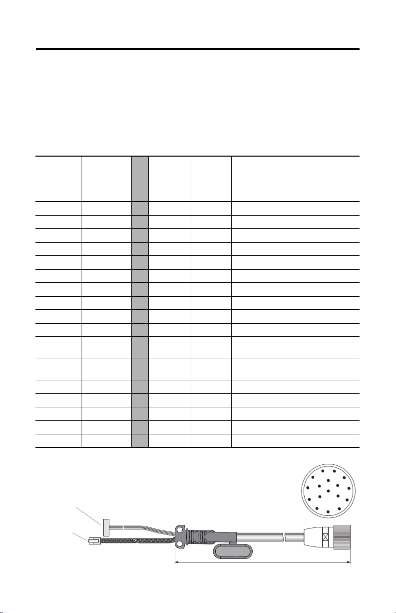
MobileView Guard G750 51
Câble de raccordement MobileView
Le câble de raccordement MobileView (2727-MRTxx) permet de connecter le
terminal MobileView au câble de connexion du boîtier de raccordement. Le câble
de raccordement est disponible en 5, 10, 15 ou 20 mètres. Il résiste à l’eau, aux
décapants, à l’huile de moteur, aux huiles de forage, à la graisse, aux lubrifiants et
aux condensats contenant de l’acide chlorhydrique.
K1 :
Connecteur
circulaire à
17 broches
Couleur des
fils du
câble de
raccordement
K3 :
connecteur
femelle à
11 broches
Broche n°
1rose
2noir
3 vert-brun
4 blanc-vert
5 gris-rose
6 rouge-bleu
7brun
8 jaune
12 vert
17 gris
9 pont vers la
10 pont vers la
broche 10
broche 9
11 violet
13 bleu
14 blanc
15 orange
16 rouge
-->> 6 - 24 V c.c.
-->> 7 - Mise à la terre
-->> 8 - Arrêt d’urgence, circuit 1, positif
-->> 9 - Arrêt d’urgence, circuit 1, négatif
-->> 10 - Arrêt d’urgence, circuit 2, positif
-->> 11 - Arrêt d’urgence, circuit 2, négatif
-->> 1 - Commutateur d’activation, circuit 1, positif
-->> 2 - Commutateur d’activation, circuit 1, négatif
-->> 3 - Commutateur d’activation, circuit 2, positif
-->> 4 - Commutateur d’activation, circuit 2, négatif
-->> - - Non utilisé
-->> - - Non utilisé
-->> 5 - Non utilisé
-->> - 1 TD+ (transmission)
-->> - 2 TD- (transmission)
-->> - 3 RD+ (réception)
-->> - 6 RD- (réception)
K2 :
connecteur
RJ-45 à
8 broches
Description
du signal
K3 : connecteur femelle
à 11 broches pour connecteur
S19 du terminal MobileView
K2 : connecteur
RJ-45 à
8 broches pour
connecteur S4
du terminal
MobileView
K1 : connecteur circulaire à 17 broches
vu côté connecteur
5, 10, 15 ou 20 mètres
Publication 2727-QS002E-MU-P
11
1
10
9
8
2
12
16
13
17
3
14
15
4
5
7
6
Page 52

52 MobileView Guard G750
Câble de connexion du boîtier de raccordement du MobileView
Le câble de connexion du boîtier de raccordement MobileView (2727-MREX1)
permet de brancher le boîtier de raccordement sur le connecteur circulaire au
niveau de la paroi de l’armoire. Ce câble a une longueur de 2 mètres. Lorsque le
terminal MobileView n’est pas connecté au boîtier de raccordement, le capuchon
anti-poussière protège le connecteur à 17 broches.
K1 :
connecteur
circulaire à
17 broches
Broche n°
Couleur des fils
du câble de
connexion du
boîtier de
raccordement
MobileView
1rose
2noir
3 vert-brun
4 blanc-vert
5 gris-rose
6 rouge-bleu
7brun
8 jaune
12 vert
17 gris
910 11 violet
13 bleu
14 blanc
15 orange
16 rouge
K2 :
connecteur
RJ-45 à
8 broches
K3 :
bornier à
12 broches
Description
du signal
-->> - 1 24 V c.c.
-->> - 2 Mise à la terre
-->> - 3 Arrêt d’urgence, circuit 1, positif
-->> - 4 Arrêt d’urgence, circuit 1, négatif
-->> - 5 Arrêt d’urgence, circuit 2, positif
-->> - 6 Arrêt d’urgence, circuit 2, négatif
-->> - 7 Commutateur d’activation, circuit 1, positif
-->> - 8 Commutateur d’activation, circuit 1, négatif
-->> - 9 Commutateur d’activation, circuit 2, positif
-->> - 10 Commutateur d’activation, circuit 2, négatif
-->> - - Non utilisé
-->> - 12 Non utilisé
-->> - 11 Non utilisé
-->> 1 - TD+ (transmission)
-->> 2 - TD- (transmission)
-->> 3 - RD+ (réception)
-->> 6 - RD- (réception)
K3 : connecteur à
12 broches pour le
bornier X1 du boîtier
de raccordement
K2 : connecteur RJ-45 à 8 broches (Ethernet)
pour la prise S1 du boîtier de raccordement
Publication 2727-QS002E-MU-P
K1 : connecteur circulaire à 17 broches,
vu côté connecteur
3
2mètres
K1 : connecteur circulaire à 17 broches,
à monter sur la paroi de l’armoire
1
11
2
12
10
16
13
14
4
5
9
17
15
7
6
8
Capuchon
anti-poussière
Page 53

MobileView Guard G750 53
Terminal MobileView
Cette section fournit des détails sur :
• le retrait du capuchon anti-poussière ;
• la connexion Ethernet ;
• l’utilisation du logement pour carte PC.
Démontage du capot arrière
Cette section explique comment retirer le capot arrière du terminal MobileView.
Une fois le capot arrière retiré, vous avez accès à la zone qui contient l’ensemble
des connecteurs.
ATTENTION
Coupez l’alimentation avant de retirer le capot arrière du
terminal MobileView.
Une fois le capot arrière retiré, le terminal MobileView est
sensible aux décharges électrostatiques.
!
1. Placez le terminal sur une surface plane et stable.
2. Retirez les 6 vis qui maintiennent le capot arrière au terminal.
3. Soulevez le capot arrière avec précaution et mettez-le de côté.
Capot arrière
Publication 2727-QS002E-MU-P
Page 54

54 MobileView Guard G750
La figure suivante montre la zone de raccordement du terminal MobileView une
fois le capot arrière retiré.
Bouton de réinitialisation
Port RS-232
pour le chargement de logiciels
Connecteur principal (S19)
pour les lignes d’alimentation
et de commande
Important : placez un
obturateur sur la prise de
câble de raccordement non
utilisée.
pour relancer Windows CE
Toutes les données non envoyées
vers le registre ou non sauvegardées
en mémoire flash sont perdues.
Broche 1
Serial
port
S19
Reset
B5
B4
00:60:B5:06:00:01
S4
Ethernet
La position des interrupteurs n’affecte
pas le fonctionnement du terminal
(pour une utilisation ultérieure)
Connecteur Ethernet (S4)
pour l’échange de données
Etiquette Ethernet
Adresse Ethernet (Mac)
2250-00001
AABBCCDDEEFF
B2 B6 B3
S6,
COM -Modul
Connecteur (non utilisé)
Languette de réduction de tension
pour la connexion du câble de raccordement
MobileView (à droite ou à gauche)
Etiquette de câble
permet d’identifier le
terminal
Déplacement du câble de raccordement du MobileView
Le câble de raccordement MobileView peut être connecté sur le côté droit ou sur le
côté gauche du terminal, selon que vous êtes gaucher ou droitier. Pour changer le
câble de côté, débranchez-le en saisissant simplement la languette de réduction de
tension et/ou la fiche, en exerçant un mouvement de torsion latérale.
Fixation du câble à droite
Connecteur
principal
(S19)
Connecteur Ethernet (S4)
Evitez de faire passer le
câble sur le renfort en T.
S6,
COM -Modul
Important : Assurez-vous que le connecteur femelle à 11 brochesK3 est bien inséré dans le connecteur
principal S19. Vérifiez le branchement de la fiche à 8 broches RJ-45 K2 dans le connecteur Ethernet S4. Evitez de
faire passer le câble sur les renforts en T. Après avoir acheminé le câble, fixez le capot arrière sur le terminal
avec les 6 vis prévues à cet effet. Serrez les vis avec un couple de serrage de 0,49 Nm pour garder le degré de
protection IP54.
Publication 2727-QS002E-MU-P
Fixation du câble à gauche
S6,
COM-Modul
Evitez de faire passer le
câble sur le renfort en T.
Page 55

MobileView Guard G750 55
Connexion Ethernet
Le terminal MobileView est équipé d’une interface 10Base-T qui prend en charge le
protocole TCP/IP à 10 MBauds pour les communications half-duplex.
Le connecteur Ethernet en S3 sur le boîtier de raccordement fournit une connexion
à un réseau Ethernet. Il utilise un connecteur modulaire à 8 broches. Le brochage
est le suivant :
Broche n° Signal Ethernet
1TD+
2TD-
3RD+
4 Non utilisé
5 Non utilisé
6RD-
7 Non utilisé
8 Non utilisé
Utilisation du logement pour carte PC
Le logement pour carte PC est une option installée en usine qui accepte les
cartes PC de type I, II et III. Les cartes PC indiquées ci-après sont disponibles
auprès d’Allen-Bradley. Le terminal n’est pas compatible avec les cartes SRAM, les
cartes Cardbus ou les cartes utilisant 12 volts pour la programmation.
Référence Description
2711-NM28 Carte flash ATA 8 Mo pour le stockage d’applications.
2711-NM216 Carte flash ATA 16 Mo pour le stockage d’applications.
2711-NM232 Carte flash ATA 32 Mo pour le stockage d’applications.
Logement pour
carte PC
Publication 2727-QS002E-MU-P
Page 56

56 MobileView Guard G750
t
Insertion de la carte PC
Levier de
verrouillage
Volet du
logement pour
carte PC
a
c
b
1
a
b
3
1. Déverrouillage du volet du logement pour carte PC (illustration 1) :
a. Couchez le terminal MobileView, l’écran posé sur une surface plane et
propre (sur un tapis antistatique de préférence). Veillez à ne pas
endommager le terminal ni ses composants.
a. Relevez le levier de verrouillage afin de libérer le volet du logement pour
carte PC.
2. Insertion de la carte PC (illustration 2) :
a. Soulevez le volet.
b. Insérez la carte PC jusqu’à ce qu’elle s’enclenche et que le bouton
d’éjection soit en saillie.
Bouton
d’éjection
Doit
s’enclencher
complètemen
2
4
ATTENTION
Vérifiez que le coin de la carte PC (avec l’encoche) est inséré
dans le logement, du côté du bouton d’éjection.
Vérifiez l’état et le positionnement du joint du volet avant de
fermer le volet du logement pour carte PC.
!
3. Fermez et verrouillez le volet (illustration 3).
4. Appuyez sur le volet jusqu’à ce qu’il s’enclenche complètement
(illustration 4).
Publication 2727-QS002E-MU-P
Page 57

MobileView Guard G750 57
Retrait de la carte PC
1
1
3
2
1. Ouvrez le volet du logement pour carte PC. Reportez-vous à la section
« Insertion de la carte PC », page 56, pour connaître la procédure à suivre.
2. Appuyez sur le bouton d’éjection du logement pour carte PC.
3. Retirez la carte PC.
4. Fermez et verrouillez le volet.
5. Appuyez sur le volet jusqu’à ce qu’il s’enclenche complètement.
Publication 2727-QS002E-MU-P
Page 58

58 MobileView Guard G750
Démarrage/Mise sous tension
1. Connectez le câble de raccordement du MobileView au câble de connexion
du boîtier de raccordement, comme indiqué à la page 48. Serrez le raccord
fileté à la main.
2. Vérifiez si le terminal MobileView affiche un écran de démarrage.
Si l’écran de démarrage n’apparaît pas, vérifiez la source d’alimentation
24 V c.c. et les connexions des câbles au niveau du boîtier de raccordement
et du terminal MobileView.
CONSEIL
L'icône du logiciel RSView ME apparaît sur l'écran de
démarrage des MobileView 2727-G7P20D1Q6 et
2727-G7P20D3Q7 uniquement.
Configuration matérielle
1. Dans la barre des tâches, sélectionnez Start>Programs>MobileView>
MV Configuration Tool (Démarrer>Programmes>MobileView>Outil de
configuration du MV).
Publication 2727-QS002E-MU-P
Page 59

MobileView Guard G750 59
La boîte de dialogue Config Tool apparaît avec l’onglet sélectionné par
défaut. Réglez les paramètres de la dalle tactile et de l’appareil à votre
convenance. Pour de plus amples informations, consultez le manuel
utilisateur du MobileView MT750 (publication 2727-UM003).
Configuration du réseau Ethernet
Pour configurer la carte de communication Ethernet intégrée à votre
terminal MobileView :
1. Toquez sur Start (Démarrer), puis sur Settings>Control Panel
(Paramètres>Panneau de configuration).
2. Toquez deux fois sur l’icône Network (Réseau).
3. Toquez sur l’onglet Adapters (Adaptateurs) dans la boîte de dialogue
Network Configuration (Configuration du réseau).
4. Sélectionnez CELAN1:Onboard Ethernet dans la liste des drivers, puis
toquez sur le bouton Properties (Propriétés).
Publication 2727-QS002E-MU-P
Page 60

60 MobileView Guard G750
5. Toquez sur l’onglet IP Address (Adresse IP) et sélectionnez Obtain an IP
Address via DHCP (Obtenir une adresse IP via DHCP) ou Specify an IP
Address (Spécifier une adresse IP), selon votre configuration réseau. Si vous
sélectionnez Specify an IP Address (Spécifier une adresse IP), renseignez
les trois zones de texte avec les informations fournies par votre
administrateur réseau ou votre fournisseur de services Internet. Utilisez le
panneau de saisie à l’écran pour saisir le texte. Vous pouvez accéder à ce
panneau en toquant sur l’icône Stylus de la barre des tâches.
L’adresse IP doit être une adresse
unique sur le réseau local.
Le masque de sous-réseau doit être
identique au masque de sous-réseau du
serveur.
La passerelle par défaut est facultative.
6. Toquez sur OK dans la boîte de dialogue des paramètres. Une fenêtre de
notification vous demandant de retirer ou de réinstaller votre carte ou de
redémarrer l’appareil afin que les nouveaux paramètres soient pris en
compte apparaît. Toquez sur le bouton OK de la fenêtre de notification.
7. Toquez sur OK dans la boîte de dialogue Network Configuration
(Configuration du réseau) et fermez le panneau de configuration.
Enregistrement des paramètres de la base de registres
ATTENTION
Les changements apportés à la configuration du matériel ou du
réseau Ethernet doivent être enregistrés dans la base de
registres ; autrement, ils seront perdus lors de la remise sous
tension du terminal MobileView.
!
Pour enregistrer les paramètres actuels de la base de registres :
1. Toquez sur le bouton Start (Démarrer), puis sélectionnez Programs>
MobileView>Registry Backup (Programmes>MobileView>Sauvegarde de
la base de registres).
2. Pour enregistrer la base de registres, toquez sur le bouton OK.
L’enregistrement de la base de registres peut prendre jusqu’à 15 secondes.
La sauvegarde de la base de registres se fermera automatiquement.
Publication 2727-QS002E-MU-P
Page 61

MobileView Guard G750 61
Démarrage des services Terminal Server
Pour connecter un terminal serveur en tant que client CE, procédez comme
suit :
1. Toquez deux fois sur le raccourci Terminal Server Client sur le bureau du
terminal MobileView ou sélectionnez l’application Terminal Server Client
depuis le dossier Programs>Terminal Server Client (Programmes>
Terminal Server Client) du menu Start (Démarrer).
2. Entrez le nom du terminal serveur ou une adresse TCP/IP valable dans la
zone Server (Serveur) à l’aide du panneau de saisie à l’écran, ou
sélectionnez un nom de serveur ou une adresse dans la zone Recent
Servers (Serveurs récents).
3. Toquez sur le bouton Connect (Connexion). Un écran de connexion de
serveur semblable à celui présenté ci-dessous apparaît.
4. Entrez votre nom d’utilisateur et votre mot de passe pour ouvrir une session
client Windows CE.
Publication 2727-QS002E-MU-P
Page 62

62 MobileView Guard G750
Arrêt/Mise hors tension
1. Fermez toutes les applications en cours sur le client Windows CE.
2. Toquez sur le bouton Start (Démarrer) de la barre des tâches du client
Windows CE. Sélectionnez Shutdown (Arrêter), puis Log Off
(Déconnexion) pour vous déconnecter du terminal serveur.
3. Retirez l’alimentation 24 V c.c. du boîtier de raccordement du MobileView
ou déconnectez le câble de raccordement MobileView du câble de
connexion du boîtier de raccordement.
CONSEIL
Les informations Heure/Date/Paramétres régionaux ne sont
pas en registrées lors d'un redémarrage.
Publication 2727-QS002E-MU-P
Page 63

MobileView Guard G750 63
Installation du support de fixation
Le support de fixation MobileView (référence 2727-MRMB1) sert à l’utilisation fixe
ou au rangement du terminal. La figure ci-dessous présente le support de fixation
avec et sans terminal installé.
Le support comporte 8 positions de réglage sur une hauteur de 320 mm. Il est
important de fixer le support par ses 4 points sur la plaque de réglage de la
hauteur. Montez le porte-câble sur le support à l’aide des vis fournies avec le
support.
Plaque pour le réglage en hauteur
Support
Support pour le câble de raccordement
MobileView
Dimensions de la plaque de réglage et trous de fixation
550 mm
526 mm
12 mm
120 mm
150 mm
22 mm
Ø
6
m
m
Ø
1
2
m
m
28 mm
20 mm
Utilisez des vis (non fournies) adaptées à la surface sur laquelle vous fixez la plaque.
Publication 2727-QS002E-MU-P
Page 64

64 MobileView Guard G750
Conformité aux directives européennes (CE)
Le produit porte le marquage CE et est certifié pour l’installation dans les pays de
l’Union européenne et de l’espace économique européen. Il a été conçu et testé en
conformité avec les directives ci-après.
Directive CEM
Cet appareil a été testé en termes de compatibilité électromagnétique (CEM) selon
la directive 89/336/CEE en application des normes suivantes, en totalité ou en
partie, répertoriées dans un dossier technique :
• EN 61000-6-4:2001 : Compatibilité électromagnétique - Norme générique
émission pour environnements industriels ;
• EN 61000-6-2:2001 : Compatibilité électromagnétique - Norme générique
immunité pour environnements industriels ;
• EN 61131-2 1994 : Automates programmables - Partie 2 : Spécifications et
essais des équipements.
Le produit décrit dans le présent document est conçu pour une utilisation en milieu
industriel.
Directive Machine
Le MobileView Guard G750 a été testé pour répondre à la directive européenne
98/37/CE relative à la sécurité des machines, en application des normes suivantes :
• EN 954-1:1996 : Sécurité des machines - Parties des systèmes de commande
relatives à la sécurité ;
• EN 292-1:1991 : Sécurité des machines - Notions fondamentales, principes
généraux de conception - Partie 1 : Terminologie de base, méthodologie ;
• EN 292-2:1991 + A1:1995 : Sécurité des machines - Notions fondamentales,
principes généraux de conception - Partie 2 : Principes techniques et
spécifications ;
• EN 418:1992 : Sécurité des machines - Equipement d’arrêt d’urgence, aspects
fonctionnels - Principes de conception ;
• EN 60204-1:1997 : Sécurité des machines - Equipement électrique des
machines - Partie 1 : Règles générales.
Une déclaration de conformité est disponible sur demande.
Publication 2727-QS002E-MU-P
Page 65

MobileView Guard G750 65
Normes et certifications
Générales
UL 508 Equipement de contrôle industriel
CSA C22.2 n° 14 Equipement de contrôle industriel
C-Tick Marquage pour toutes les lois en vigueur
Compatibilité électromagnétique (CEM)
EN 61000-6-4:2001 Compatibilité électromagnétique - Norme générique émission pour
EN 61000-6-2:2001 Compatibilité électromagnétique - Norme générique immunité pour
CEI 61131-2 version finalisée,
chap. 7 et 8
Sécurité de fonctionnement
CEI 61131-2, EN61131-2:1994
+ A11:1996 + A12:2000
CEI 60204-1, EN60204-1:1997 Sécurité des machines - Equipement électrique des machines -
EN 50178:1997 Equipement électronique utilisé dans les circuits de puissance
environnements industriels
environnements industriels
Automates programmables - Spécifications et essais des équipements
Automates programmables - Spécifications et essais des équipements
Partie 1 : Règles générales
Normes relatives à la sécurité des machines
EN 614-1:1995 Sécurité des machines - Principes ergonomiques de conception -
EN 894-1:1997, -2, -3 Sécurité des machines - Spécifications ergonomiques pour la
ISO 13849-1:1999, EN 954-1:1996 Sécurité des machines - Parties des systèmes de commande relative à
ISO DIS 12100-1, EN 292-1:1991 Sécurité des machines - Notions fondamentales, principes généraux de
ISO DIS 12100-2,
EN 292-2:1991 + A1:1995
ISO 13850:1996, EN 418:1992 Sécurité des machines - Equipement d’arrêt d’urgence, aspects
EN 60204-1:1997 Sécurité des machines - Equipement électrique des machines -
Partie 1 : Terminologie et principes généraux
conception des dispositifs de signalisation et des organes de service
la sécurité - Partie 1 : Principes généraux de conception
conception - Partie 1 : Terminologie de base, méthodologie
Sécurité des machines - Notions fondamentales, principes généraux de
conception - Partie 2 : Principes techniques et spécifications
fonctionnels - Principes de conception
Partie 1 : Règles générales
Publication 2727-QS002E-MU-P
Page 66

66 MobileView Guard G750
Normes pour MobileView utilisé dans les systèmes robotisés
EN 775:1992 Robots manipulateurs industriels - Sécurité
ANSI/RIA R15.06 - 1999 Robots industriels et systèmes robotisés - Exigences de sécurité (norme
ANSI/RIA R15.02/1 Robots industriels et systèmes robotisés - Boîtiers de commande de
UL 1740 Robots et équipement robotisé
Normes pour MobileView utilisé dans les centres d’usinage
ISO 11161 Systèmes d’automatisation industrielle - Sécurité des systèmes de fabrication
EN 12417:2001 Machines outils - Sécurité - Centres d’usinage
américaine)
robots portatifs - Critères de conception ergonomique
intégrés - Prescriptions fondamentales
Publication 2727-QS002E-MU-P
Page 67

MobileView Guard G750 67
Configurations du MobileView Guard G750
Caractéristiques 2727-G7P20D1P4 2727-G7P20D1P5 2727-G7P20D1Q6 2727-G7P20D3Q7
Ecran VGA 7,7 pouces Oui
Interface IrDA Oui
Commutateur d’activation
à 3 positions
Bouton d’arrêt d’urgence
à 2 circuits (3)
Mémoire 16 Mo de DRAM/32 Mo de Flash 64 Mo de DRAM/ 64 Mo de Flash
Logement pour carte PC Non Oui
Communications Ethernet 10Base-T
Eléments opérationnels Non Non
Système d’exploitation
Windows CE
RSView ME Non Oui
Application client léger Oui
Non Oui
Oui
Bouton-poussoir avec
marquage désactivé (5)
Commutateur à clé (6)
Bouton-poussoir avec
marquage activé(7)
Potentiomètre (1)
Volant de manœuvre
électronique (2)
Oui
Non
Accessoires
Référence Description
2727-MRT5 Câble de raccordement MobileView Guard (5 mètres) : connecte le terminal
2727-MRT10 Câble de raccordement MobileView Guard (10 mètres): connecte le terminal
2727-MRT15 Câble de raccordement MobileView Guard (15 mètres): connecte le terminal
2727-MRT20 Câble de raccordement MobileView Guard (20 mètres): connecte le terminal
2727-MRJB1 Boîtier de raccordement MobileView Guard : fournit des connexions à l’automate, à Ethernet,
2727-MREX1 Câble de connexion du boîtier de raccordement MobileView Guard (2 mètres) : connecte le
2727-MRC1 Câble de liaison MobileView Guard (4 mètres) : connecte le terminal MobileView Guard à
2727-MRMB1 Support de fixation MobileView Guard pour utilisation fixe ou le rangement du terminal
2727-MRSDK1 Kit de développement MobileView Guard pour Windows CE.
MobileView Guard au câble de connexion du boîtier de raccordement.
MobileView Guard au câble de connexion du boîtier de raccordement.
MobileView Guard au câble de connexion du boîtier de raccordement.
MobileView Guard au câble de connexion du boîtier de raccordement.
à l’alimentation, au bouton-poussoir d’arrêt d’urgence et aux commutateurs d’activation.
câble de raccordement MobileView Guard au boîtier de raccordement.
un PC.
MobileView Guard.
Publication 2727-QS002E-MU-P
Page 68

68 MobileView Guard G750
Spécifications
Générales
Processeur Intel StrongARM SA-1110 / 206 MHz
Système d’exploitation
2727-G7P20D1P4, -G7P20D1P4
2727-G7P20D1Q6, -G7P20D3Q7
Mémoire 2 tailles : 16 Mode DRAM/32 Mo de Flash ou
Ecran LCD à matrice passive VGA 7 pouces, 256 couleurs
Dalle tactile Analogique résistive 7,7 pouces
Pavé numérique Commutateurs convexes de réaction à pression tactile,
Boîtier Double paroi
Dimensions
Diamètre
Profondeur sans la poignée
Profondeur avec la poignée
Poids 1550 grammes (hors options)
Microsoft Windows CE, Version 3.0
Microsoft Windows CE, Version 4.1
64 Mo de DRAM/64 Mo de Flash
en acier inoxydable
Résistant à la graisse, à l’huile, aux lubrifiants et à l’alcool
Sans silicone
Classe d’inflammabilité : UL 94-V0
290 mm
80 mm
130 mm
Electriques
Tension d’alimentation nominale Très basse tension de sécurité 24 V c.c.
Plage de tensions d’alimentation 18 V c.c. à 32 V c.c.
Courant d’entrée 300 mA maximum
Courant d’appel crête 5,6 A maximum
Alimentation Temps de maintien de 10 ms minimum (EN 61131-2:1994 et
Environnement
Température de fonctionnement
Température de stockage
Humidité relative (sans condensation)
Degré de protection IP54
Résistance aux vibrations
(en fonctionnement)
Tenue aux chocs (en fonctionnement) 25 G pendant 11 ms (CEI60068-2-27)
EN 50178:1997)
°C à 50 °C
0
-25
°C à +70 °C
5 à 95 % de 0
10 Hz <
57 Hz <
°C à 50 °C
f < 57 Hz avec 0,15 mm
f < 150 Hz avec 2 G
Publication 2727-QS002E-MU-P
Page 69

Schnellstart
MobileView Guard G750
(Best.-Nr. 2727-G7P20D1P4, 2727-G7P20D1P5, 2727-G7P20D1Q6, 2727-G7P20D3Q7)
Deutsch
Ausführlichere Informationen zu MobileView Guard G750 finden Sie in der
Publikation 2727-UM002.
Eine kostenlose elektronische Version der Publikation 2727-UM002 erhalten Sie:
• auf der Installations-CD
• www.support.rockwellautomation.com
www.theautomationbookstore.com
Inhalt . . .
Wichtige Hinweise für den Anwender ............................................................................ 70
Beschreibung des Terminals MobileView Guard G750 ................................................... 71
Sicherheitsvorkehrungen und -elemente ......................................................................... 72
Montage und Verdrahtung des MobileView-Anschlusskastens ..................................... 79
Entfernen der hinteren Abdeckung .................................................................................. 86
Ethernet-Verbindung ........................................................................................................ 88
Verwenden des PC-Kartensteckplatzes ........................................................................... 88
Einschalten ....................................................................................................................... 91
Hardwarekonfiguration .................................................................................................... 91
Ethernet-Netzwerkkonfiguration ..................................................................................... 92
Speichern von Registrierungseinstellungen .................................................................... 93
Aufrufen der Terminal-Dienste ........................................................................................ 95
Ausschalten ..................................................................................................................... 96
Installation der Montagehalterung .................................................................................. 97
Konformität mit EU-Richtlinien ........................................................................................ 98
Normen und amtliche Zulassungen ................................................................................. 99
Konfiguration des Terminals MobileView Guard G750 ................................................. 100
Zubehör .......................................................................................................................... 101
Technische Daten ........................................................................................................... 102
Publikation 2727-QS002E-MU-P
Page 70

70 MobileView Guard G750
Wichtige Hinweise für den Anwender
Aufgrund der vielfältigen Einsatzmöglichkeiten der in dieser Publikation
beschriebenen Produkte müssen die für die Anwendung und den Einsatz dieses
Geräts verantwortlichen Personen sicherstellen, dass jede Anwendung bzw. jeder
Einsatz alle Leistungs- und Sicherheitsanforderungen, einschließlich sämtlicher
anwendbarer Gesetze, Vorschriften, Bestimmungen und Normen erfüllt.
Die Abbildungen, Diagramme und Aufbaubeispiele in diesem Handbuch dienen
ausschließlich der Veranschaulichung. Aufgrund der unterschiedlichen Anforderungen der jeweiligen Applikation kann Rockwell Automation keine Verantwortung
oder Haftung (einschließlich Haftung für geistiges Eigentum) für den tatsächlichen
Einsatz auf der Grundlage dieser Beispiele übernehmen.
In der Rockwell Automation-Publikation SGI-1.1, Safety Guidelines for the
Application, Installation and Maintenance of Solid-State Controls (erhältlich bei
Ihrem Rockwell Automation-Vertriebsbüro), werden einige wichtige Unterschiede
zwischen elektronischen und elektromechanischen Geräten erläutert. Diese müssen
bei der Verwendung der in diesem Handbuch beschriebenen Produkte
berücksichtigt werden.
Die Vervielfältigung des Inhalts dieser urheberrechtlich geschützten Publikation,
ganz oder auszugsweise, bedarf der schriftlichen Genehmigung von Rockwell
Automation.
In diesem Handbuch verwenden wir die folgenden Hinweise, um Sie auf bestimmte
Sicherheitsaspekte aufmerksam zu machen:
ACHTUNG
Dieser Hinweis macht Sie auf Vorgehensweisen und Zustände
aufmerksam, die zu Verletzungen oder Tod, Sachschäden oder
wirtschaftlichen Verlusten führen können.
!
Diese Achtungshinweise helfen Ihnen:
• eine Gefahr zu erkennen
• die Gefahr zu vermeiden
• die Folgen abzuschätzen
WICHTIG
Publikation 2727-QS002E-MU-P
Dieser Hinweis enthält Informationen, die für den
erfolgreichen Einsatz und das Verstehen des Produkts
besonders wichtig sind.
Page 71

MobileView Guard G750 71
Beschreibung des Terminals MobileView Guard G750
2
1
3
11
12
4
8
5
1 Potentiometer mit linearer Auflösung von 0–127 (Option)
2 Elektronisches Handrad, 50 Impulse/Umdrehung, –32 768 bis +32 768 (Option)
3 Not-Aus-Schalter, zwei Stromkreise, Öffner-Kontakte, 24 V DC, maximal 500 mA (Option)
4 Folientastatur mit Druckpunkten – Standard-Windows-Tastaturbetrieb
5 Beleuchteter Drucktaster, Schließer, AUS-Kennzeichnung, gelbe LED (Option)
6 Schlüsselschalter mit 3 Positionen (Option)
7 Beleuchteter Drucktaster, Schließer, EIN-Kennzeichnung, gelbe LED (Option)
8 7,7-Zoll-VGA-Passivmatrix-Farb-LCD-Anzeige (640 x 480 Pixel) mit analogem resistivem
9 Aktivierungsschalter mit 3 Positionen und zwei Stromkreisen (auf jeder Seite des Griffs) für
10 IrDA-Tastatur-/Druckerschnittstelle, Baudrate: 9600 Baud oder 115,2 kBaud
11 Griff für links- oder rechtshändige Bedienung
12 Einzelsteckplatz-PC-Kartenschnittstelle für Karten vom Typ I, II oder III (Option)
13 Zugentlastung für Verbindungskabel (im Lieferumfang des Kabels enthalten)
14 Hintere Abdeckung des Anschlussfachs
15 Stecker für Kabelausgang bei Nichtverwendung (entspricht Schutzgrad IP54)
Touchscreen
Sicherheitsanwendungen
7
6
10
9
15
14
13
Publikation 2727-QS002E-MU-P
Page 72

72 MobileView Guard G750
Sicherheitsvorkehrungen und -elemente
In diesem Abschnitt werden allgemeine Sicherheitsvorkehrungen sowie wichtige
Informationen zum Netzteil, Not-Aus-Schalter und Aktivierungsschalter des
MobileView Guard G750 behandelt.
Allgemeine Sicherheitshinweise
Die Anweisungen in diesem Dokument müssen unter allen Umständen befolgt
werden. Andernfalls kann es zu gefährlichen Situationen kommen, oder in das
Terminal integrierte Sicherheitsfunktionen können ausfallen.
Neben den in diesem Dokument genannten Sicherheitsvorkehrungen sollten Sie
weitere der Situation angemessene Sicherheitsvorkehrungen und
Unfallverhütungsmaßnahmen treffen.
Publikation 2727-QS002E-MU-P
Page 73

MobileView Guard G750 73
ACHTUNG
!
• Stellen Sie sicher, dass unterbrochene Vorgänge nach
einem Stromausfall oder Leistungsabfall ordnungsgemäß
neu gestartet werden können. Es dürfen zu keinem
Zeitpunkt, auch nicht für kurze Zeit, gefährliche Betriebsbedingungen entstehen.
• Wenn Fehler im Automationssystem zu Verletzungen oder
schweren Schäden an Geräten und Ausrüstung führen
könnten, treffen Sie zusätzliche externe Sicherheitsvorkehrungen, um sicherzustellen, dass sich das System
ständig in einem sicheren Betriebszustand befindet.
• Stellen Sie sicher, dass Unbefugte keine Einstellungen oder
Speicheränderungen vornehmen können, die zu
gefährlichen Situationen führen könnten.
• Überprüfen Sie regelmäßig die Funktionsfähigkeit der
sicherheitsbezogenen Teile (Not-Aus- und Aktivierungsschalter).
• Wenn das MobileView-Terminal und die Steuerung nicht
über eine Punkt-zu-Punkt-Verbindung kommunizieren,
können z. B. Keypad-Eingaben verzögert übertragen
werden. Wir empfehlen für eine höhere Übertragungsgeschwindigkeit die Verwendung eines Ethernet-Schalters
zwischen dem MobileView-Terminal und der Steuerung.
• Überprüfen Sie sicherheitsbezogene Teile, wenn das
Terminal starken Erschütterungen ausgesetzt war (z. B.
wenn es fallen gelassen wurde).
• Wenn die Maschine/Anlage über das MobileView-Terminal
betrieben wird, stellen Sie sicher, dass alle Vorgänge am
MobileView-Terminal ausgeführt werden (C.F.
ANSI/RIA 15.06).
• Wenn Sie eine PC-Karte mit dem MobileView verwenden,
vergewissern Sie sich immer, dass die PC-Karte ordnungsgemäß eingesetzt ist. Nach einer starken Belastung bleibt
die PC-Kartenabdeckung geschlossen. Stellen Sie sicher,
dass die Karte korrekt eingesetzt ist, sodass ein guter
elektrischer Kontakt besteht.
• Wenn das MobileView-Terminal im manuellen Modus
eingesetzt wird (z. B. Unterweisung des Roboters), stellen
Sie sicher, dass der Roboter sich langsamer bewegt (C.F.
ANSI/RIA 15.06).
Publikation 2727-QS002E-MU-P
Page 74

74 MobileView Guard G750
Handhabung des MobileView Guard-Terminals
Zusätzliche Handhabungshinweise zur Vermeidung von Fehlfunktionen und Beschädigungen des Terminals finden Sie im Handbuch zum MobileView Guard
G750.
Spannungsversorgung
ACHTUNG
!
• Das Gerät entspricht der Sicherheitsklasse III gemäß
EN 61131-2 und EN 50178. Das 24-V-Netzteil für das Gerät
muss eine angemessene Isolierung zwischen den Sicherheits-Niederspannungskreisen und den Netzspannungskreisen bieten (z. B. durch Sicherheitstransformatoren oder
ähnliche Komponenten).
• Schützen Sie den Stromkreis durch eine 3,15-A-Sicherung.
• Die Nenn-Speisespannung des MobileView-Terminals
(ohne MobileView-Verbindungskabel) beträgt +24 V DC
(Speisespannungsbereich: 18–32 V DC).
Typischer Stromverbrauch:
–300 mA bei 24 V DC
–400 mA bei 18 V DC
Beachten Sie beim Planen der Spannungsversorgung den
Spannungsabfall im MobileView-Verbindungskabel.
Im Folgenden werden die Spezifikationen der Versorgungsleitungen im Kabel aufgeführt:
Querschnitt: AWG 24 (0,24 mm2)
Material: Kupferlitze
Leitungswiderstand: <90 Ohm/km
Aktivierungsschalter
Der elektronische Aktivierungsschalter setzt die Aktivierungsgeräte für Maschinen
in bestimmten Betriebsmodi als Sicherheitsfunktion um. Der Aktivierungsschalter ist
Teil des MobileView-Terminals.
Jede Maschine verfügt über einen normalen und einen speziellen Betriebsmodus.
• Im normalen Betriebsmodus verhindern Schutzvorrichtungen und
Betriebsschutzgeräte den Zugriff und garantieren Sicherheit. Die speziellen
Betriebsmodi werden zur Aufrechterhaltung des normalen Betriebsmodus
verwendet.
Publikation 2727-QS002E-MU-P
Page 75

MobileView Guard G750 75
• Im speziellen Betriebsmodus muss die Sicherheit auf andere Weise
gewährleistet werden, da der Bediener sich in gefährlichen Bereichen der
Maschine bewegen muss und zielgerichtete Arbeitsschritte möglich sein
müssen. In diesem Fall muss die Gefahr eingeschätzt und auf dieser
Grundlage eine verminderte Geschwindigkeit der Maschine festgelegt
werden. Eine Bewegung ist nur dann möglich, wenn ein Aktivierungsgerät
eingeschaltet ist. Der Benutzer muss hinsichtlich der Handhabung des Geräts
geschult worden sein, und ihm muss der Verwendungszweck genauestens
bekannt sein. Die sicherheitsbezogenen Teile der Steuerung zur Reduzierung
der Geschwindigkeit und für das Aktivierungsgerät müssen so konstruiert
sein, dass sie der Sicherheitskategorie nach EN 954-1, die bei der
Gefahrenanalyse definiert wurde, entsprechen.
Für die Sicherheitskategorie 3 entsprechend EN 954-1 muss der Aktivierungsschalter mit 2 Stromkreisen implementiert werden.
In EN 60204-1 wird die Funktionsweise des Aktivierungsgeräts beschrieben.
Aufgrund der jüngsten Erkenntnisse aus der Unfallanalyse und da entsprechende
technische Lösungen verfügbar sind, wird heute der Aktivierungsschalter mit
3 Positionen verwendet. Bei den Positionen 1 und 3 des Aktivierungsschalters
handelt es sich um AUS-Funktionen. Nur die mittlere Position dient zur Aktivierung.
EN 60204-1 ist mit IEC 60204-1 identisch. Der Aktivierungsschalter mit 3 Positionen
ist also international anerkannt.
Der Aktivierungsschalter besteht aus einem Bedienelement mit 3 Positionen und
getrennter Auswertungselektronik. Zu den wesentlichen Funktionen zählen die
beiden Dauerstromkreise zwischen den Aktivierungselementen und den Verbindungsklemmen. Für die Auswertungskreise werden andere Technologien und
Stromkreise verwendet. Aufgrund der elektronischen Umschaltkontakte hängt ihre
Lebensdauer nicht von der Last ab, solange die Nennlastwerte (ohmsch, induktiv
und kapazitiv) nicht überschritten werden.
ACHTUNG
!
• Aktivierungsschalter dürfen nur verwendet werden, wenn
der Bediener, der den Schalter aktiviert, die gefährliche
Situation rechtzeitig genug erkennt, um gegebenenfalls
entsprechend tätig zu werden.
• Der Aktivierungsschalter wird nur zur Aktivierung von
Befehlen bei der Durchführung gefährlicher Bewegungen
verwendet. Die Befehle müssen über ein separates
Bedienungselement (Taste am Terminal) aktiviert werden.
Nur Personen, die berechtigt sind, den Aktivierungsschalter zu betätigen, dürfen im gefährlichen Bereich
arbeiten.
• Die Aktivierungsschalter am MobileView Guard-Terminal
verfügen immer über zwei Stromkreise.
Publikation 2727-QS002E-MU-P
Page 76

76 MobileView Guard G750
Verbindungsbeispiel mit einem Sicherheits-Steuerrelais
Das unten stehende Diagramm zeigt die mögliche Verkabelung für Aktivierungsschalter
bei Verwendung eines PST-Sicherheits-Steuerrelais von PILZ zur Erfüllung von Sicherheitskategorie 3. Weitere Informationen finden Sie in der PST-Dokumentation von PILZ.
MobileView
(2 Aktivierungsschalter mit je
3 Positionen und 2 Stromkreisen)
123123 321321
ZT1
L
123123 321321
ZT2
L
ZT1
R
ZT2
R
Control cabinet
+24 VDC
F2
F3
4A(t)
F1
1A
Feedback
control lo op
KA KB
X1 X2
A1(+) 23 S11
K1
PILZ
PST1
K2
6A(f)
4A(t)
or
or
6A(f)
13
3,15A
S19:
K3:
DC/DC
converter
67
67
Evaluation electronics
Circu it 1 Circu it 2
12 34
12 34
ZTxy ....... enabling switch x
y
MobileView-Verbindungskabel
K1:
K3:
+24V GND ED1+ ED1- ED2+ ED2-
X1
7 8 12 17K1: 1 2
7 8 12 1712
17-Stift-Steckverbinder
MobileView-Zwischenkabel
Klemmenleisten-Anschlussbuchse
K3 am Anschlusskasten
Stecker X1 am Anschlusskasten
Anschlusskasten
X2
+24V GND ED1+ ED1- ED2+ ED2-K4:
GND
F4
S12
Stecker X2 am
Anschlusskasten
Klemmenleisten-Anschlussbuchse
K4 am Anschlusskasten
L1 L2 L3
KA
KB
Aktivierung von
gefährlichen
Bewegungen
A2(-)
GND
14 24 S23 S24
KA KB
GND GND
Publikation 2727-QS002E-MU-P
M
Hinweis: Alle KA- und KB-Kontakte müssen
zwangsgeführt sein.
Page 77

Daten zum Schaltelement
MobileView Guard G750 77
Nennspannung 24 V DC (typisch)
Nennstrom 500 mA (typisch)
Kurzschlussstrom Stromkreis 1: maximal 1,9 A
Maximale induktive Belastung (bei 500 mA) Stromkreis 1: >1 H
Maximale kapazitive Last Stromkreis 1: kein Grenzwert, da Transistor thermisch
32 V DC (maximal)
Stromkreis 2: maximal 600 mA
Stromkreis 2: maximal 320 mH
geschützt ist
Stromkreis 2: maximal 500 µF
Die Schaltelemente der Aktivierungsschalter sind gegen Verpolung geschützt. Die
Ausgänge beider Stromkreise sind gegen Kurzschlüsse und Überlast geschützt.
• Stromkreis 1: thermisch geschützter Stromkreis
• Stromkreis 2: rückläufig geschützter Stromkreis
Vorhersehbarer Missbrauch des Aktivierungsschalters
Unter vorhersehbarem Missbrauch versteht man das Feststellen des Aktivierungsschalters auf die Aktivierungsposition. Der vorhersehbare Missbrauch des
Aktivierungsschalters muss eingeschränkt werden. Wir empfehlen folgende
Maßnahmen, durch die die Maschine im manuellen Modus gestoppt wird.
• Überprüfung des Aktivierungsschalters beim Einschalten der
Maschine/Anlage und Überprüfung des Aktivierungsschalters beim Wechsel
vom automatischen in den manuellen Betriebsmodus. (Der Aktivierungsschalter darf sich nicht in der Aktivierungsposition befinden.)
• Der Aktivierungsschalter muss innerhalb eines bestimmten Zeitraums
losgelassen und wieder neu betätigt werden. Der Zeitraum muss
entsprechend der Aktivität festgelegt werden.
Publikation 2727-QS002E-MU-P
Page 78

78 MobileView Guard G750
Not-Aus-Schalter
Der Not-Aus-Schalter des MobileView-Terminals entspricht den Anforderungen von
EN 418. Er muss auf der Grundlage der Gefahrenanalyse für die Maschine als
Not-Aus-Schalter der Kategorie 0 oder 1 entworfen werden (siehe EN 60204-1,
Kapitel 9.2.5.4.2). Die Verbindung zwischen zwangsgeführten Kontakten und einem
geeigneten Überwachungssystem muss der Sicherheitskategorie entsprechen, die
im Rahmen der Gefahrenanalyse (nach EN 954-1) für die Maschine definiert wurde.
Der Not-Aus-Schalter verfügt über zwei potenzialfreie Öffner-Kontakte für den
Anschluss externer Peripheriegeräte, eine Nenn-Betriebsspannung von 24 V
(Sicherheits-Kleinspannung entsprechend EN 61131-2 und EN 50178) und einen
maximalen Betriebsstrom von 500 mA.
.
ACHTUNG
!
• Wenn der Not-Aus-Schalter nicht in den Not-Aus-Stromkreis
eingebunden ist, muss das MobileView-Terminal außer
Reichweite der Bediener aufbewahrt werden. Bedenken Sie,
dass der Bediener im Gefahrenfall möglicherweise instinktiv
den nächsten Not-Aus-Schalter betätigt. Dies könnte fatale
Folgen haben, falls der Not-Aus-Schalter nicht funktioniert.
• Not-Aus-Funktionen müssen optional in allen Betriebsmodi
erhalten bleiben. Das Zurücksetzen eines aktivierten Not-AusSchalters darf nicht zu einem unkontrollierten Neustart von
Maschinen und Installationen führen.
• Der Not-Aus-Schalter ersetzt keine anderen
Sicherheitsvorrichtungen.
Gefahrenanalyse für Maschinen
Bei der Gefahrenanalyse müssen die folgenden Standards angewendet werden:
• EN 292-1 „Sicherheit von Maschinen; Grundbegriffe, allgemeine
Gestaltungsleitsätze“
• EN 1050 „Sicherheit von Maschinen – Leitsätze zur Risikobeurteilung“
• EN 954-1 „Sicherheit von Maschinen – Sicherheitsbezogene Teile von
Steuerungen“
• ANSI/RIA 15.06-1999 „American National Standard for Industrial Robots and
Robot Systems – Safety Requirements (Section 9)“
• ANSI B11.TR3-2000 „Risk Assessment and Risk Reduction – A guide to
estimate, evaluate and reduce risks associated with machine tools“
In den Sicherheitskategorien (B, 1, 2, 3, 4) wird die Struktur sicherheitsbezogener
Teile in einer Maschine festgelegt. Die Kategorien werden auf der Grundlage der
Gefahrenanalyse bestimmt.
Auf Seite 76 sehen Sie ein MobileView-Terminal, dessen Aktivierungsfunktion der
Sicherheitskategorie 3 entspricht. In diesem Terminal wird ein PST-Steuerrelais von
PILZ verwendet. Die gesamte Maschine muss entsprechend den Richtlinien dieser
Sicherheitskategorie konstruiert sein.
Publikation 2727-QS002E-MU-P
Page 79

MobileView Guard G750 79
Montage und Verdrahtung des MobileView-Anschlusskastens
Mit dem MobileView-Anschlusskasten (2727-MRJB1) wird das MobileView-Terminal
in das Steuerungssystem integriert. Der Anschlusskasten wird auf einer DIN-Schiene
montiert.
S1 RJ-45-Buchse zum Anschließen der MobileView-Datenleitungen
S2 9-Stift-DSUB-Buchse (zur späteren Verwendung)
S3 RJS-45-Buchse zum Ethernet-Netzwerk
X1 12-Stift-Stecker zum Anschließen des Anschlusskabels
X2 12-Stift-Stecker (wird mit Klemmenleisten-Anschlussbuchse geliefert) zum Anschließen
Stift 1, 24 V DC
(mit Klemmen-
leisten-Anschluss-
buchse K3)
folgender Komponenten:
• 24-V-DC-Netzteil
• Not-Aus-Schalter
• Aktivierungsschalter
60 mm
+24V
GND
ES1+
ES1-
ES2+
ES2-
X1
ED1+
ED1-
ED2+
ED2-
24V DC
ON LY
TERM INAL IN
RS422 OUT
150 mm
108 mm
S1
Stift 1, 24 V DC
(mit Klemmen-
leisten-Anschluss-
buchse K4)
Erdungsschraube
ACHTUNG
!
+24V
GND
ES1+
ES1-
ES2+
X2
ES2-
ED1+
ED1-
ED2+
ED2-
ETHERNET OUT
S2
162 mm
S3
Erdungs-
DIN-Schienen-Riegel
schraube
Der Anschlusskasten und das MobileView-Terminal entsprechen
der Sicherheitsklasse III gemäß EN 61131-2 und EN 50178.
Stellen Sie beim Anschließen des Terminals sicher, dass es sich
bei allen am MobileView-Terminal vorliegenden Spannungen um
Sicherheits-Kleinspannungen handelt, indem Sie einen Sicherheitstransformator oder eine ähnliche Komponente verwenden.
Publikation 2727-QS002E-MU-P
Zugentlastung
Page 80

80 MobileView Guard G750
Montage des Anschlusskastens auf einer DIN-Schiene
Montieren Sie den MobileView-Anschlusskasten mithilfe einer DIN-Schiene in
einem Gehäuse.
So installieren Sie den Anschlusskasten auf einer DIN-Schiene:
1. Montieren Sie die DIN-Schiene.
2. Haken Sie die obere Vertiefung über die DIN-Schiene.
3. Drücken Sie den Anschlusskasten gegen die Schiene und lassen Sie ihn in
der richtigen Position einrasten.
So entfernen Sie den Anschlusskasten von der DIN-Schiene:
1. Setzen Sie einen Schraubendreher im DIN-Schienen-Riegel unten am
Anschlusskasten an.
2. Halten Sie den Anschlusskasten fest, und drücken Sie den Riegel nach
unten, bis sich der Anschlusskasten von der DIN-Schiene gelöst hat.
Publikation 2727-QS002E-MU-P
Page 81

MobileView Guard G750 81
Verbinden des MobileView-Terminals mit dem Anschlusskasten
In der folgenden Abbildung sehen Sie, wie das MobileView-Terminal mit dem
Anschlusskasten verbunden wird.
MobileView-Terminal
ESC
7 8 9
5 6
4
3
1 2
.
-
0
MobileViewVerbindungskabel
Ausschnitt des
Steckverbinders
24 mm
25 ± 0,1 mm
r
o
n
r
u
Er
R
KETOP
Staubabdeckung
K1,
Typischer Steuerungsschrank
Stift 1, 24 V DC
X1/K3
MobileView-
Klemmenverbindungen
Stift 1, 24 V DC
X2/K4
Sicherheitsgerät-
Verbindungen
maximale Wandstärke 5 mm
Anschlusskabel 2m
Erdungsschraube
zum Verbinden von
Erde mit Anschlusskasten
Anschlusskasten
24V DC
ON LY
+24V
TERM INAL IN
GND
ES1+
ES1-
ES2+
ES2-
ED1+
ED1-
ED2+
ED2-
RS 422 OUT
+24V
GND
ES1+
ES1-
ES2+
ES2-
ED1+
ED1-
ED2+
ED2-
ETHERNET OUT
10 Base-T-Verbindung
zum EthernetNetzwerk
Anschlusskabel-
befestigung
S1
S2
S3
Kabel-Freiraum auf beiden Seiten der Gehäusewand
130 mm
Verbindungs-
kabel
K1-Anschluss
108 mm
Anschluss-
kabel
Publikation 2727-QS002E-MU-P
Page 82

82 MobileView Guard G750
Kontaktstifte und Verkabelung des Anschlusskastens
MobileView
S19
S4
Verbindungskabel
K3
6
7
8
9
10
11
1
2
3
4
5
K2
1
2
3
6
MobileView-
rosa
schwarz
grün-braun
weiß-grün
grau-rosa
rot-blau
braun
gelb
grün
grau
lila
blau
weiß
orange
rot
MobileView-
Anschlusskabel
K1
1
2
3
4
5
6
7
8
12
17
11
9
10
13
14
15
16
rosa
schwarz
grün-braun
weiß-grün
grau-rosa
rot-blau
braun
gelb
grün
grau
lila
blau
weiß
orange
rot
Spätere Verwendung
Zum Ethernet-Netzwerk
K3
X1
24 V DC
1
2
0VDC
Not-Aus, Stromkr. 1, pos.
3
Not-Aus, Stromkr. 1, neg.
4
5
Not-Aus, Stromkr. 2, pos.
6
Not-Aus, Stromkr. 2, neg.
7
Akt.-Sch., Stromkr. 1, pos.
8
Akt.-Sch., Stromkr. 1, neg.
9
Akt.-Sch., Stromkr. 2, pos.
10
Akt.-Sch., Stromkr. 2, neg.
11
Nicht verwendet
12
Nicht verwendet
K2
S1
1
2
3
4
5
6
7
8
S2
1
2
3
4
5
6
7
8
9
S3
1
TD+
2
TD–
3
RD+
4
5
6
RD–
7
8
Anschlusskasten
X2 K4
1
2
3
4
5
6
7
8
9
10
11
12
+24V
GND
ES1+
ES1–
ES2+
ES2–
ED1+
ED–
ED2+
ED2–
Publikation 2727-QS002E-MU-P
Page 83

MobileView Guard G750 83
Anforderungen an die Spannungsversorgung
Elektrische Spezifikationen
24 V DC Spannungsversorgung Verwenden Sie ein Netzteil mit 24 V DC
Erdung Verbinden Sie das Erdungskabel mit dem Anschlusskasten,
Sicherheits-Kleinspannung
Speisespannungsbereich: 18 V DC bis 32 V DC
Stromverbrauch: 300 mA bei 24 V DC
Einschaltstoßstrom: maximal 5,6 A
indem Sie die auf Seite 81 dargestellte Erdungsschraube
verwenden.
ACHTUNG
!
• Das Gerät entspricht der Sicherheitsklasse III gemäß
EN 61131-2 und EN 50178. Das 24-V-Netzteil für das Gerät
muss eine angemessene Isolierung zwischen den Sicherheits-Niederspannungskreisen und den Netzspannungskreisen bieten (z. B. durch Sicherheitstransformatoren oder
ähnliche Komponenten).
• Der Stromkreis muss durch eine 3,5-A-Sicherung geschützt
sein.
• Die direkte Nenn-Speisespannung des MobileViewTerminals (ohne MobileView-Verbindungskabel) beträgt
+24 V DC (Speisespannungsbereich: 18–32 V DC).
Typischer Stromverbrauch:
–300 mA bei 24 V DC
–400 mA bei 18 V DC
Beachten Sie beim Planen der Spannungsversorgung den
Spannungsabfall im Verbindungskabel.
Im Folgenden werden die Spezifikationen der Versorgungsleitungen im Kabel aufgeführt:
Querschnitt: AWG 24 (0,24 mm
Material: Kupferlitze
Leitungswiderstand: <90 Ohm/km
2
)
Publikation 2727-QS002E-MU-P
Page 84

84 MobileView Guard G750
MobileView-Verbindungskabel
Das MobileView-Verbindungskabel (2727-MRTxx) verbindet das MobileViewTerminal mit dem Anschlusskabel. Die Länge des Kabels beträgt 5, 10, 15 oder 20
Meter. Das Kabel ist resistent gegen Wasser, Reinigungsmittel, Motor- und Bohröl,
Schmierfett, Gleitmittel und Kondensate, die Salzsäure enthalten.
K1, runder
17-Stift-Steck-
verbinder,
Verbindungs-
kabel,
Drahtfarbe
K3, 11-
Stift-
Buchse
Stift-Nr.
1rosa
2 schwarz
3 grün-braun
4 weiß-grün
5grau-rosa
6rot-blau
7braun
8gelb
12 grün
17 grau
9 Brücke zu Stift 10
10 Brücke zu Stift 9
11 lila
13 blau
14 weiß
15 orange
16 rot
-->> 6 – 24 V DC
-->> 7 – 0 V DC
-->> 8 – Not-Aus, Stromkreis 1, positiv
-->> 9 – Not-Aus, Stromkreis 1, negativ
-->> 10 – Not-Aus, Stromkreis 2, positiv
-->> 11 – Not-Aus, Stromkreis 2, negativ
-->> 1 – Aktivierungsschalter, Stromkreis 1, positiv
-->> 2 – Aktivierungsschalter, Stromkreis 1, negativ
-->> 3 – Aktivierungsschalter, Stromkreis 2, positiv
-->> 4 – Aktivierungsschalter, Stromkreis 2, negativ
-->> – – Nicht verwendet
-->> – – Nicht verwendet
-->> 5 – Nicht verwendet
-->> – 1 TD+ (übertragen)
-->> – 2 TD– (übertragen)
-->> – 3 RD+ (empfangen)
-->> – 6 RD– (empfangen)
K2,
8-Stift-
RJ-45
Signal-
beschreibung
K3, 11-StiftBuchse zu S19 am
MobileView-Terminal
K2,
8-Stift-RJ-45Buchse zu S4
am MobileViewTer mi nal
Publikation 2727-QS002E-MU-P
K1, runder 17-Stift-Steckverbinder,
von der Anschlussseite gesehen
5, 10, 15 oder 20 Meter
11
1
10
9
8
2
12
16
13
17
3
14
15
4
5
7
6
Page 85
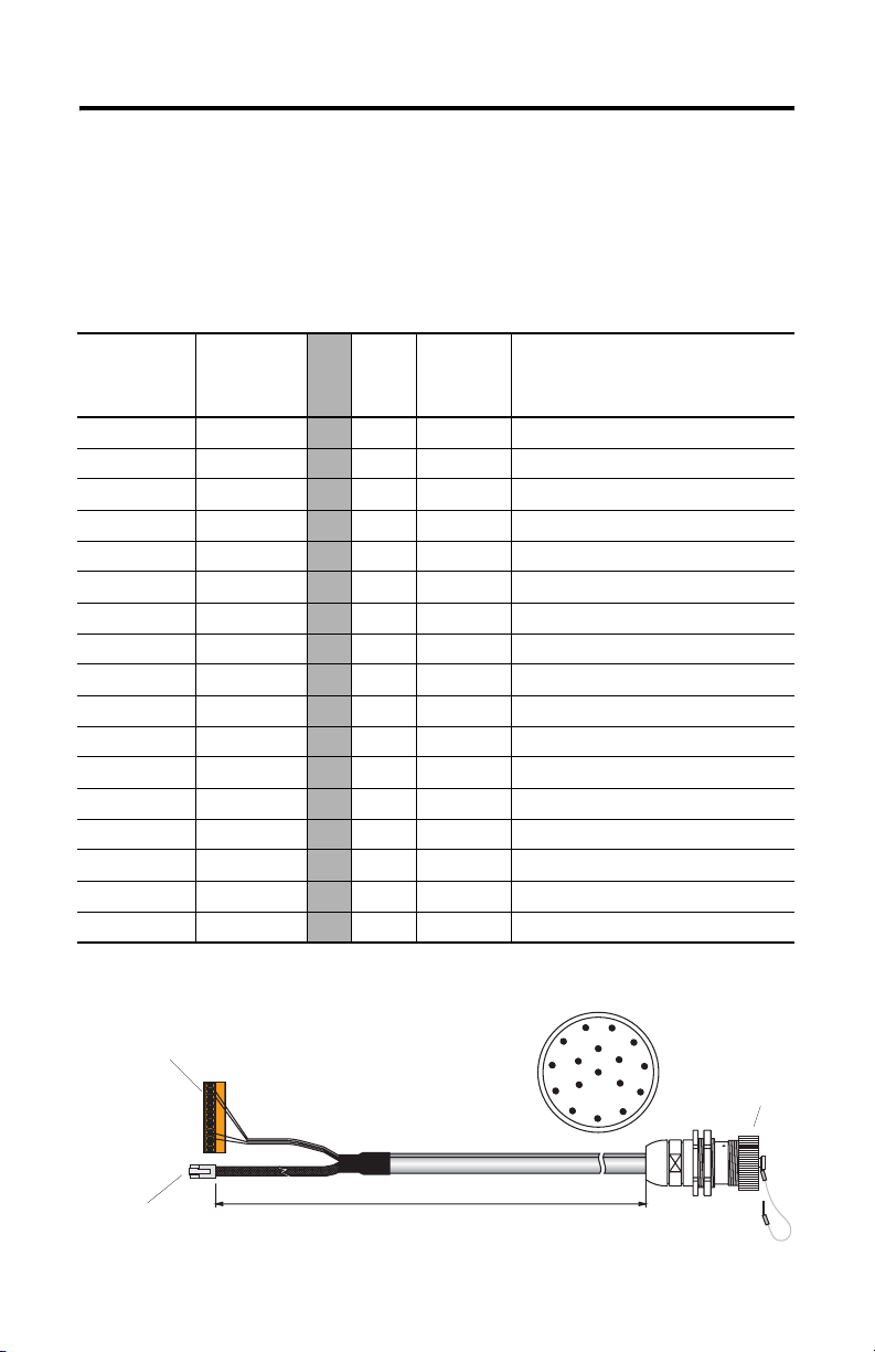
MobileView Guard G750 85
MobileView-Anschlusskabel
Das MobileView-Anschlusskabel (2727-MREX1) verbindet den Anschlusskasten mit
dem runden Steckverbinder in der Gehäusewand. Das Kabel ist 2 Meter lang. Wenn
das MobileView-Terminal nicht mit dem Anschlusskasten verbunden ist, wird der
17-Stift-Steckverbinder durch die Staubabdeckung geschützt.
K1, runder
17-Stift-Steck-
verbinder,
Anschluss-
kabel,
Drahtfarbe
Stift-Nr.
1rosa
2 schwarz
3 grün-braun
4 weiß-grün
5 grau-rosa
6rot-blau
7braun
8gelb
12 grün
17 grau
9–
10 –
11 lila
13 blau
14 weiß
15 orange
16 rot
K3, 12-Stift-Verbindung
für Klemmenleiste X1 am
Anschlusskasten
K2,
8-Stift-
RJ-45
K3, 12-Stift-
Klemmen-
leiste
Signalbeschreibung
-->> – 1 24 V DC
-->> – 2 0 V DC
-->> – 3 Not-Aus, Stromkreis 1, positiv
-->> – 4 Not-Aus, Stromkreis 1, negativ
-->> – 5 Not-Aus, Stromkreis 2, positiv
-->> – 6 Not-Aus, Stromkreis 2, negativ
-->> – 7 Aktivierungsschalter, Stromkreis 1, positiv
-->> – 8 Aktivierungsschalter, Stromkreis 1, negativ
-->> – 9 Aktivierungsschalter, Stromkreis 2, positiv
-->> – 10 Aktivierungsschalter, Stromkreis 2, negativ
-->> – – Nicht verwendet
-->> – 12 Nicht verwendet
-->> – 11 Nicht verwendet
-->> 1 – TD+ (übertragen)
-->> 2 – TD– (übertragen)
-->> 3 – RD+ (empfangen)
-->> 6 – RD– (empfangen)
K1, runder 17-Stift-Steckverbinder,
von der Anschlussseite gesehen
1
11
2
12
10
16
13
3
14
4
5
9
17
15
8
Staubabdeckung
7
6
K2, 8-Stift-RJ-45-Buchse
(Ethernet) für S1 am
Anschlusskasten
2 Meter
K1, runder 17-Stift-Steckverbinder
zur Befestigung am Gehäuse
Publikation 2727-QS002E-MU-P
Page 86

86 MobileView Guard G750
MobileView-Terminal
Dieser Abschnitt enthält Informationen zu folgenden Themen:
• Entfernen der hinteren Abdeckung des MobileView-Terminals
• Ethernet-Verbindung
• Verwenden des PC-Kartensteckplatzes
Entfernen der hinteren Abdeckung
In diesem Abschnitt erfahren Sie, wie Sie die hintere Abdeckung des
MobileView-Terminals entfernen. Wenn die hintere Abdeckung entfernt ist, haben
Sie Zugang zu dem Bereich, in dem sich alle Verbindungen befinden.
ACHTUNG
Schalten Sie die Stromversorgung aus, bevor Sie die hintere
Abdeckung des MobileView-Terminals entfernen.
Wenn die hintere Abdeckung entfernt ist, kann es im
MobileView-Terminal zu elektrostatischer Entladung kommen.
!
1. Stellen Sie das Terminal auf eine feste ebene Oberfläche.
2. Entfernen Sie die 6 Schrauben, mit denen die hintere Abdeckung am
Terminal befestigt ist.
3. Entfernen Sie die hintere Abdeckung vorsichtig, und legen Sie sie beiseite.
Hintere Abdeckung
Publikation 2727-QS002E-MU-P
Page 87

MobileView Guard G750 87
In der folgenden Abbildung ist der Anschlussbereich des MobileView-Terminals bei
entfernter hinterer Abdeckung dargestellt.
Rücksetz-Taste
RS-232-Anschluss
zum Herunterladen von
Software
Haupt-Steckverbinder (S19)
für Spannungsversorgung und
Steuerungsleitungen
Wichtig: Installieren Sie
den Steckverbinder am
unbenutzten Ausgang des
MobileView-Verbindungskabels.
zum Neustarten von Windows CE
Alle Daten, die nicht in die Registry- Datei
ausgelagert oder im Flash-Speicher
abgelegt werden, gehen verloren.
Stift 1
Serial
port
S19
Reset
B5
B4
00:60:B5:06:00:01
AABBCCDDEEFF
S4
Ethernet
Schalterstellung wirkt sich nicht
auf Terminalbetrieb aus (zur
späteren Verwendung)
Ethernet-Steckverbinder (S4)
zum Datenaustausch
Ethernet-Kennzeichnung
Ethernet (Mac)-Adresse
2250-00001
S6,
COM -Modul
B2 B6 B3
Anschluss (nicht verwendet)
Zugentlastung
zum Anschluss des MobileViewVerbindungskabels (links oder rechts)
Kabelbeschriftung
zur eindeutigen
Bestimmung des
Terminals
Umlegen des MobileView-Verbindungskabels
Das MobileView-Verbindungskabel kann für Rechts- und Linkshänder wahlweise an
der rechten oder der linken Seite des Terminals angebracht werden. Um die Seite
zu wechseln, fassen Sie das Kabel an der Zugentlastung und/oder dem Stecker und
ziehen es mit einer ruckelnden Bewegung heraus.
Anschließen des Kabels auf der rechten Seite
Haupt-
Steckver-
binder
S4, Ethernet-Steckverbinder
Kabel nicht über die
T-Stütze führen.
S6,
COM -Modul
Wichtig: Achten Sie darauf, dass die 11-Stift-Anschlussbuchse K3 beim Einstecken vollständig in
den Haupt-Steckverbinder S19 einrastet. Stellen Sie sicher, dass die 8-Stift-RJ-45-Buchse korrekt im
Ethernet-Steckverbinder S4 sitzt. Führen Sie das Kabel nicht über die T-Stützen. Wenn das Kabel verlegt ist,
bringen Sie die Abdeckung wieder an, und sichern Sie sie mit den 6 Schrauben. Ziehen Sie die Schrauben
mit einem Anzugsmoment von 0,5 Nm an, um den Schutzgrad IP54 beizubehalten.
Anschließen des Kabels auf der linken Seite
S19,
Kabel nicht über die
T-Stütze führen.
Publikation 2727-QS002E-MU-P
S6,
COM-Modul
Page 88

88 MobileView Guard G750
Ethernet-Verbindung
Das MobileView-Terminal ist mit einer 10Base-T-Schnittstelle ausgestattet, die das
TCP/IP-Protokoll für die Halbduplex-Kommunikation mit einer Baudrate von
10 MBaud unterstützt.
Der Ethernet-Steckverbinder an S3 am Anschlusskasten ermöglicht die Verbindung
mit einem Ethernet-Netzwerk. Für die Steckverbindung wird eine modulare
8-Stift-Buchse verwendet. Es gibt folgende Kontaktstifte:
Stift-Nr. Ethernet-Signal
1TD+
2TD–
3RD+
4 Nicht verwendet
5 Nicht verwendet
6RD–
7 Nicht verwendet
8 Nicht verwendet
Verwenden des PC-Kartensteckplatzes
Beim PC-Kartensteckplatz handelt es sich um eine werkseitig installierte Option.
Unterstützt werden PC-Karten vom Typ I, II und III. Die folgenden PC-Karten sind
bei Rockwell Automation erhältlich. Das Terminal unterstützt weder SRAM-Karten,
Cardbus-Karten noch Karten, die mit 12 Volt programmiert werden.
Bestell-Nr. Beschreibung
2711-NM28 8-MB-ATA-Flash-Speicherkarte zum Speichern von Anwendungen
2711-NM216 16-MB-ATA-Flash-Speicherkarte zum Speichern von Anwendungen
2711-NM232 32-MB-ATA-Flash-Speicherkarte zum Speichern von Anwendungen
PC-Kartenfach
Publikation 2727-QS002E-MU-P
Page 89

Einsetzen der PC-Karte
MobileView Guard G750 89
Verschlusshebel
PC-Kartenabdeckung
a
c
b
1
a
b
3
1. Entsperren der PC-Kartenabdeckung (siehe Abbildung 1).
a. Legen Sie das MobileView-Terminal mit der Anzeige nach unten auf einen
flachen, sauberen Tisch (vorzugsweise auf eine ESP-Fläche). Achten Sie
darauf, dass Sie das Terminal und seine Komponenten nicht beschädigen.
b. Heben Sie den Verschlusshebel an, sodass sich die PC-Kartenabdeckung
löst.
Auswurftaste
Muss
vollständig
einrasten
2
4
2. Einsetzen einer PC-Karte (siehe Abbildung 2).
a. Heben Sie die Abdeckung an.
b. Setzen Sie die PC-Karte so ein, dass sie einrastet und die Auswurftaste
nach außen gedrückt wird.
ACHTUNG
Vergewissern Sie sich, dass die andere Ecke der PC-Karte (mit
der Einkerbung) sich im Schlitz an der Seite der Auswurftaste
befindet.
Überprüfen Sie den Zustand und die Position der Abdeckungs-
!
dichtung, bevor Sie die PC-Kartenabdeckung schließen.
3. Schließen und Verriegeln der Abdeckung (siehe Abbildung 3).
4. Drücken Sie die Abdeckung nach unten, bis sie vollständig einrastet (siehe
Abbildung 4).
Publikation 2727-QS002E-MU-P
Page 90

90 MobileView Guard G750
Entfernen der PC-Karte
1
1
3
2
1. Öffnen Sie die PC-Kartenabdeckung. Die genaue Vorgehensweise finden Sie
unter „Einsetzen der PC-Karte“ auf Seite 89.
2. Drücken Sie die Auswurftaste am PC-Kartensteckplatz.
3. Entfernen Sie die PC-Karte.
4. Schließen und verriegeln Sie die Abdeckung.
5. Drücken Sie die Abdeckung nach unten, bis sie vollständig einrastet.
Publikation 2727-QS002E-MU-P
Page 91

MobileView Guard G750 91
Einschalten
1. Befestigen Sie das MobileView-Verbindungskabel am Anschlusskasten, wie
auf Seite 81 gezeigt. Ziehen Sie die Schraubkupplung handfest an.
2. Überprüfen Sie, ob am MobileView-Terminal der Start-Bildschirm angezeigt
wird.
Wenn der Start-Bildschirm nicht angezeigt wird, überprüfen Sie die
24-V-DC-Stromzufuhr sowie die Kabelverbindungen am Anschlusskasten
und am MobileView-Monitor.
TIPP
Ein Symbol für die RSView ME-Software erscheint nur auf den
Start-Bildschirmen der MobileView 2727-G7P20D1Q6 und
2727-G7P20D3Q7.
Hardwarekonfiguration
1. Wählen Sie in der Task-Leiste Start > Programs (Programme) >
MobileView > MV Configuration Tool
(MobileView-Konfigurationsprogramm).
Publikation 2727-QS002E-MU-P
Page 92
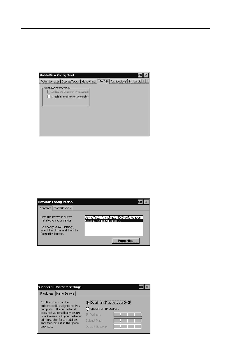
92 MobileView Guard G750
Das Dialogfeld „Config Tool“ wird angezeigt, die Standardregisterkarte ist
ausgewählt. Passen Sie die Touchscreen- und Geräteeinstellungen nach
Bedarf an. Weitere Informationen finden Sie in der Publikation 2727-UM002,
dem Benutzerhandbuch zu MobileView Guard G750.
Ethernet-Netzwerkkonfiguration
So konfigurieren Sie die Ethernet-Kommunikationshardware Ihres
MobileView-Terminals:
1. Tippen Sie auf Start, und wählen Sie Settings (Einstellungen) > Control
Panel (Systemsteuerung).
2. Tippen Sie zweimal kurz auf das Netzwerk-Symbol.
3. Tippen Sie im Dialogfeld für die Netzwerkkonfiguration auf die Registerkarte
Adapters (Netzwerkkarten).
4. Wählen Sie in der Treiberliste den Eintrag CELAN1:Onboard Ethernet, und
tippen Sie anschließend auf die Schaltfläche Properties (Eigenschaften).
Publikation 2727-QS002E-MU-P
Page 93

MobileView Guard G750 93
5. Tippen Sie auf die Registerkarte IP Address (IP-Adresse), und wählen Sie je
nach Ihrer Netzwerkkonfiguration entweder Obtain an IP Address via
DHCP (IP-Adresse über DHCP aufrufen) oder Specify an IP Address
(IP-Adresse angeben) aus. Wenn Sie die Option Specify an IP Address
wählen, geben Sie in den drei Textfeldern die Angaben ein, die Sie von
Ihrem Netzwerkadministrator oder Internet- dienstanbieter erhalten haben.
Geben Sie den Text über das On-Screen- Keyboard ein. Sie können das
Keyboard aufrufen, indem Sie in der Task- Leiste auf das Bleistiftsymbol
tippen.
Bei IP Address (IP-Adresse) muss es
sich um eine eindeutige Adresse im
LAN handeln.
Subnet Mask (Subnet-Maske) muss
mit der Subnet-Maske des Servers
identisch sein.
Die Eingabe bei Default Gateway
(Standard-Gateway) ist optional.
6. Tippen Sie im Dialogfeld mit den Einstellungen auf die Schaltfläche OK. Sie
werden in einem Benachrichtigungsfenster dazu aufgefordert, die Karte
entweder zu entfernen oder neu zu installieren, bzw. das Gerät neu zu
starten, damit die neuen Einstellungen wirksam werden. Tippen Sie im
Benachrichtigungsfenster auf die Schaltfläche OK.
7. Tippen Sie im Dialogfeld “Network Configuration” (Netzwerkkonfiguration)
auf OK, und schließen Sie die Systemsteuerung.
Speichern von Registrierungseinstellungen
ACHTUNG
Alle Änderungen an der Hardwarekonfiguration oder der
Ethernet-Netzwerkkonfiguration müssen in der Registry-Datei
gespeichert werden, da sie sonst beim Aus- und Einschalten der
Versorgungsspannung des MobileView-Terminals verloren gehen.
!
Publikation 2727-QS002E-MU-P
Page 94

94 MobileView Guard G750
So speichern Sie aktuelle Registrierungseinstellungen:
1. Tippen Sie auf Start, und wählen Sie Programs (Programme) >
MobileView > Registry Backup (Registrierungssicherung).
2. Tippen Sie auf die Schaltfläche OK, um die Registrierung zu speichern. Das
Speichern der Registrierung kann bis zu 15 Sekunden dauern. Die Sicherung
der Registrierung wird automatisch beendet.
Publikation 2727-QS002E-MU-P
Page 95

MobileView Guard G750 95
Aufrufen der Terminal-Dienste
So stellen Sie als CE-Client eine Verbindung zum Terminal-Server her:
1. Tippen Sie zweimal kurz auf die Verknüpfung zum Terminal-Server-Client
auf dem Desktop des MobileView-Terminals, oder wählen Sie die TerminalServer-Client-Anwendung über Start > Programs (Programme) > Terminal
Server Client (Terminal-Server-Client) aus.
2. Geben Sie über das On-Screen-Keyboard den Namen des Terminal-Servers
oder eine gültige TCP/IP-Adresse in das Feld Server ein, oder wählen Sie im
Feld Recent Servers (Bisher verwendete Server) einen Servernamen oder
eine Adresse aus.
3. Tippen Sie auf die Schaltfläche Connect (Verbindung herstellen). Daraufhin
wird ein Anmeldungsfenster wie in der nachstehenden Abbildung angezeigt.
4. Geben Sie Ihren Benutzernamen und Ihr Kennwort ein, um sich als aktiver
CE-Client anzumelden.
Publikation 2727-QS002E-MU-P
Page 96

96 MobileView Guard G750
Ausschalten
1. Beenden Sie alle Anwendungen, die auf dem CE-Client ausgeführt werden.
2. Tippen Sie in der Task-Leiste auf Start. Wählen Sie Shutdown
(Herunterfahren) und anschließend Log Off (Abmelden), um die
Verbindung zum Terminal-Server zu trennen.
Trennen Sie das 24-V-DC-Netzteil vom MobileView-Anschlusskasten, oder
ziehen Sie das MobileView-Verbindungskabel vom Anschlusskabel ab.
TIPP
Bei einem Neustart werden Zeit/Datum/Regionale Einstellungen
nicht gespeichert.
Publikation 2727-QS002E-MU-P
Page 97
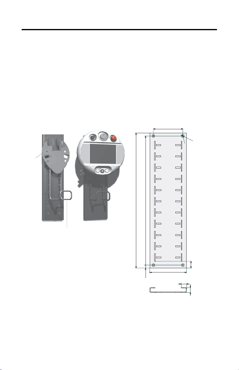
MobileView Guard G750 97
Installation der Montagehalterung
Die MobileView-Montagehalterung (Bestell-Nr. 2727-MRMB1) wird für den
stationären Betrieb sowie die Lagerung des Terminals verwendet. Die folgende
Abbildung zeigt die Montagehalterung mit und ohne montiertes Terminal.
Der Träger kann auf einer Höhe von 320 mm in acht verschiedenen Positionen
angebracht werden. Der Träger muss unbedingt an allen vier Punkten an der Platte
zur Höheneinstellung befestigt werden. Montieren Sie den Kabelhalter mithilfe der
mit der Halterung gelieferten Schrauben am Träger.
Platte zur Höheneinstellung
Träger
Halter für
MobileView-Verbindungskabel
Maße und Befestigungsbohrungen der Platte
550 mm
526 mm
12 mm
120 mm
150 mm
22 mm
D
u
r
c
h
D
m
.
u
6
m
r
c
m
h
m
.
1
2
m
m
28 mm
20 mm
Verwenden Sie geeignete Schrauben (nicht im Lieferumfang enthalten), um die
Platte zu montieren.
Publikation 2727-QS002E-MU-P
Page 98

98 MobileView Guard G750
Konformität mit EU-Richtlinien
Das Produkt trägt ein CE-Zeichen und wurde zur Installation in der Europäischen
Union und in EWR-Gebieten zugelassen. Es wurde gemäß der folgenden Richtlinien
entwickelt und getestet.
EMV-Richtlinie
Dieses Gerät wurde gemäß den Anforderungen der Richtlinie 89/336/EWG des Rats
der Europäischen Union für elektromagnetische Verträglichkeit (EMV) unter
Verwendung der folgenden Normen, ganz oder auszugsweise, und der technischen
Spezifikationen geprüft:
• EN 61000-6-4:2001 EMV – Fachgrundnormen – Fachgrundnorm Störaussendung für Industriebereich
• EN 61000-6-2:2001 EMV – Fachgrundnormen – Störfestigkeit für Industriebereich
• EN 61131-2:1994 – Speicherprogrammierbare Steuerungen, Teil 2 – Betriebsmittelanforderungen und Prüfungen
Dieses Produkt ist für den Einsatz in einer industriellen Umgebung bestimmt.
Maschinenrichtlinie
Das Terminal MobileView Guard G750 wurde gemäß den Anforderungen der
Richtlinie 98/37/EWG des Rats der Europäischen Union zur Sicherheit von
Maschinen unter Verwendung der folgenden Normen geprüft:
• EN 954-1:1996 – Sicherheit von Maschinen – Sicherheitsbezogene Teile von
Steuerungen
• EN 292-1:1991 – Grundbegriffe, allgemeine Gestaltungsleitsätze
• EN 292-2: 1991/A1:1995 – Technische Leitsätze und Spezifikationen
• EN 418:1992 – Sicherheit von Maschinen – NOT-AUS-Einrichtung,
funktionelle Aspekte, Gestaltungsleitsätze
• EN 60204-1:1997 – Sicherheit von Maschinen – Elektrische Ausrüstung von
Maschinen – Allgemeine Anforderungen
Auf Wunsch ist eine Konformitätserklärung erhältlich.
Publikation 2727-QS002E-MU-P
Page 99

MobileView Guard G750 99
Normen und amtliche Zulassungen
Allgemein
UL 508 Industrielles Steuerungsgerät
CSA C22.2 Nr. 14 Industrielles Steuerungsgerät
C-Tick Für alle zutreffenden Bestimmungen gekennzeichnet.
Elektromagnetische Verträglichkeit (EMV)
EN 61000-6-4:2001 EMV – Fachgrundnorm Störaussendung, Industriebereich
EN 61000-6-2:2001 EMV – Fachgrundnorm Störfestigkeit, Industriebereich
IEC 61131-2 entg.
Entwurf Kapitel 7+8
Betriebssicherheit
IEC 61131-2, EN 61131-2:1994+
A11:1996 + A12:2000
IEC 60204-1, EN 60204-1:1997 Sicherheit von Maschinen– Elektrische Ausrüstung von Maschinen –
EN 50178:1997 Ausrüstung von Starkstromanlagen mit elektronischen Betriebsmitteln
Maschinenstandards
EN 614-1: 1995 Ergonomische Gestaltungsgrundsätze
EN 894-1:1997, -2, -3 Ergonomische Anforderungen an die Gestaltung von Anzeigen und
ISO 13849-1:1999, EN 954-1: 1996 Sicherheitsbezogene Teile von Steuerungen
ISO DIS 12100-1, EN 292-1: 1991 Grundbegriffe, allgemeine Gestaltungsleitsätze
ISO DIS 12100-2,
EN 292-2:1991 + A1:1995
ISO 13850:1996, EN 418: 1992 Sicherheit von Maschinen – NOT-AUS – Gestaltungsleitsätze
EN 60204-1: 1997 Sicherheit von Maschinen – Elektrische Ausrüstung von Maschinen –
Programmierbare Steuerungen – Betriebsmittelanforderungen und
Prüfungen
Programmierbare Steuerungen – Betriebsmittelanforderungen und
Prüfungen
Allgemeine Anforderungen
Stellteilen
Technische Leitsätze und Spezifikationen
Allgemeine Anforderungen
Normen für die Verwendung von MobileView in Robotersystemen
EN 775:1992 Industrieroboter
ANSI/RIA R15.06 – 1999 Amerikanische Norm für Industrieroboter und Robotersysteme –
ANSI/RIA R15.02/1 Amerikanische Norm für Industrieroboter und Robotersysteme –
UL 1740 Roboter und Roboterzubehör
Normen für die Verwendung von MobileView in maschinellen Zentren
ISO 11161 Industrielle Automatisierungssysteme – Sicherheit von integrierten
EN 12417:2001 Sicherheit von Werkzeugmaschinen – Bearbeitungszentren
Sicherheitsanforderungen
Montagesteuerung für Roboter – Design-Kriterien für Human
Engineering
Fertigungssystemen
Publikation 2727-QS002E-MU-P
Page 100

100 MobileView Guard G750
Konfiguration des Terminals MobileView Guard G750
Komponenten 2727-G7P20D1P4 2727-G7P20D1P5 2727-G7P20D1Q6
7,7-Zoll-VGA-Anzeige Ja
IrDA-Schnittstelle Ja
Aktivierungsschalter mit
3 Positionen
Not-Aus-Schalter mit
2 Stromkreisen – Position 3
Speicher 16 MB DRAM/32 MB Flash 64 MB DRAM/64 MB Flash
PC-Kartensteckplatz Nein Ja
Kommunikation 10Base-T Ethernet
Betriebselemente Nein Nein
Windows CE Ja
RSView ME Nein Ja
Thin Client-Anwendung Ja
Nein Ja
Ja
Drucktaster mit
AUS- Kennzeichnung
– Position 5
Schlüsselschalter –
Position 6
Drucktaster mit EINKennzeichnung –
Position 7
Potentiometer –
Position 1
Elektronisches
Handrad – Position 2
2727-G7P20D3Q7
Nein
Publikation 2727-QS002E-MU-P
 Loading...