

Page 1

Installation Instructions
Feeder Circuit Breaker Units Secure Support Pan and Change Door Latch
Catalog Numbers
2193F and 2100M
About This Publication
Top ic Pa ge
About This Publication 1
Required Tools 1
Important User Information 2
Before You Begin 4
Secure the Support Pan and Change the Door Latch 4
Remove the Feeder Unit from the Section 4
Remove the Unit Below the Feeder Unit 6
Secure the Support Pans 6
Install Latch Angle Bracket 8
Install Units 9
Install New Door Latch Screw and Label 10
Additional Resources 12
This document provides instructions on how to replace one of the
¼-turn door latches found in the upper right corner of the unit door with a new
screw-type door latch. This document also covers the addition of fasteners to the
support pans for these plug-in units.
Required Tools
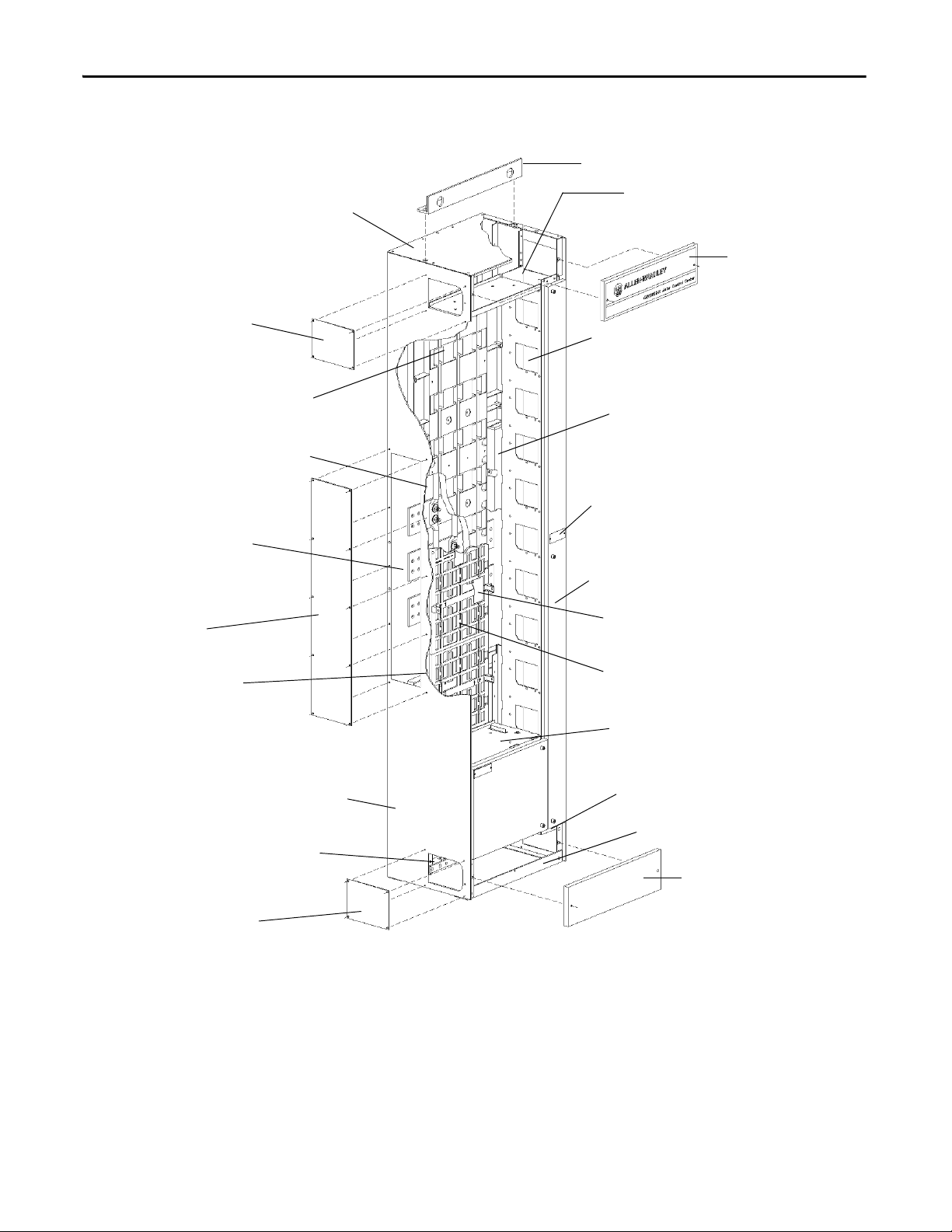
Refer to Figure 1
control center section (MCC).
This document is intended for 1.5 space factor, and larger, plug-in units with a
225/250 A frame circuit breaker, including the following units:
• Bulletin 2193F plug-in units (Feeder unit), circuit breaker
• Bulletin 2100M plug-in units, circuit breaker with catalog code ‘43CT’
through ‘45CT’ and ‘43CM’ through ‘45CM’
You need the following tools:
• Small flat-bladed screwdriver
• 5/16 in. and a 3/8 in. socket wrench
• Optional, battery operated screwdriver
for a description of the parts of a CENTERLINE 2100 motor
Page 2

Feeder Circuit Breaker Units Secure Support Pan and Change Door Latch
IMPORTANT
Important User Information
Solid-state equipment has operational characteristics differing from those of electromechanical equipment. Safety
Guidelines for the Application, Installation and Maintenance of Solid State Controls (publication SGI-1.1
your local Rockwell Automation sales office or online at http://www.rockwellautomation.com/literature/
important differences between solid-state equipment and hard-wired electromechanical devices. Because of this difference,
and also because of the wide variety of uses for solid-state equipment, all persons responsible for applying this equipment
must satisfy themselves that each intended application of this equipment is acceptable.
In no event will Rockwell Automation, Inc. be responsible or liable for indirect or consequential damages resulting from the
use or application of this equipment.
The examples and diagrams in this manual are included solely for illustrative purposes. Because of the many variables and
requirements associated with any particular installation, Rockwell Automation, Inc. cannot assume responsibility or
liability for actual use based on the examples and diagrams.
No patent liability is assumed by Rockwell Automation, Inc. with respect to use of information, circuits, equipment, or
software described in this manual.
Reproduction of the contents of this manual, in whole or in part, without written permission of Rockwell Automation, Inc.,
is prohibited.
available from
) describes some
Throughout this manual, when necessary, we use notes to make you aware of safety considerations.
WARNING: Identifies information about practices or circumstances that can cause an explosion in a hazardous environment,
which may lead to personal injury or death, property damage, or economic loss.
AT TE NT IO N: Identifies information about practices or circumstances that can lead to personal injury or death, property
damage, or economic loss. Attentions help you identify a hazard, avoid a hazard, and recognize the consequence.
SHOCK HAZARD: Labels may be on or inside the equipment, for example, a drive or motor, to alert people that dangerous
voltage may be present.
BURN HAZARD: Labels may be on or inside the equipment, for example, a drive or motor, to alert people that surfaces may
reach dangerous temperatures.
Identifies information that is critical for successful application and understanding of the product.
2 Rockwell Automation Publication 2100-IN091A-EN-P - April 2013
Page 3
Feeder Circuit Breaker Units Secure Support Pan and Change Door Latch
Lifting Angle
Top Horizontal
Wireway Baffle
Top Horizontal
Wireway Cover
Right Hand Unit Support
Vertical Wireway Assembly
Bus Splice Access Cover
Section Nameplate
Vertical Wireway Door
Vertical to Horizontal Bus
Connection Access Cover
Vertical Bus Support Cover
Unit Support Pan
Sealing Strap
Top and Bottom
Bottom Support Angle
Bottom Horizontal
Wireway Cover
Left Hand
Bottom End Closing Plate
Horizontal Ground Bus
Top or Bottom
Left Hand Side Plate Assembly
Vertical Plug-in
Ground Bus
Left Hand
Center End Plate
Horizontal Power Bus
Vertical Power Bus
Horizontal and Vertical
Bus Support
Left Hand
Top End Closing Plate
Removable Top Plate
Figure 1 - Structure Diagram
3 Rockwell Automation Publication 2100-IN091A-EN-P - April 2013
Page 4
Feeder Circuit Breaker Units Secure Support Pan and Change Door Latch
Before You Begin
ATTENTION: De-energize all power sources to the Motor Control Center before
opening any section or unit doors. Verify that all power is OFF, as per NFPA 70E,
Standards for Electrical Safety Requirements. Failure to de-energize all power
sources can result in severe injury or death.
ATT EN TI ON : To prevent personal injury or damage to equipment, make sure
that the unit operator handle is in the OFF/O position before removing plug-in
units.
ATT EN TI ON : De-energize all units before installing or removing.
When installing or removing MCC units, when possible, de-energize, lockout, and
tag-out all sources of power to the MCC. If the MCC units are installed or removed
with power applied to the main power bus, follow established electrical safety
work practices. Refer to the NFPA 70E Standard for Electrical Safety in the
Workplace publication.
Review your company safety lockout and tag-out procedure.
If power sources are connected to the motor control center, use extreme caution
when inserting units. All buses and the line sides of the inserted units are
energized, and contact with these parts can cause injury or death.
All covers and doors must be in place before applying power to the MCC. If units are
removed, they must be replaced with the appropriate items, such as units, doors,
and unit support pans.
Secure the Support Pan and Change the Door Latch
Remove the Feeder Unit from the Section
To secure the support pan and change the door latch, complete these steps.
1. Remove the Feeder Unit from the Section
2. Remove the Unit Below the Feeder Unit
3. Secure the Support Pans
4. Install Latch Angle Bracket
5. Install Units
6. Install New Door Latch Screw and Label
Follow these steps to remove the Feeder unit.
1. Make sure the operator handle is in the OFF/O position.
2. Verify that all control power and other power sources are off in the Motor
Control Center lineup.
3. Open the Feeder unit door completely.
4. Mark the phase on each load wire in the Feeder unit to assist with later
wire connection.
.
.
.
.
.
.
4 Rockwell Automation Publication 2100-IN091A-EN-P - April 2013
Page 5

Feeder Circuit Breaker Units Secure Support Pan and Change Door Latch
IMPORTANT
Top Captive Latch Bottom Captive Latch
5. Disconnect the Feeder unit load wires and pull the load wires away from
the unit so the unit can be removed from the section.
6. Mark and disconnect control circuit wires if they interfere with the
removal of the Feeder unit.
7. Remove other cables or devices that prevent the unit from being
withdrawn.
8. Disengage the captive latches at the front of the unit, one at the top and
one at the bottom of the unit.
Units that are 2.0 space factor and larger have two latches at the top.
Units that are 0.5 space factor do not have captive latches. After you open the
unit door, push the latch mechanism to the left with your right hand and then
remove the unit from the section.
9. Pull the unit forward (outward), approximately 3 in. (7.5 cm) out of the
MCC, by using the handle provided at the lower left of the unit and the
tab in the upper right of the unit as finger holds.
Reposition your hands as necessary to properly support the unit while you
are removing the unit from the MCC.
ATTENTION: Plug-in MCC units can be heavy or awkward to handle.
Use an assistant or a platform lift device if necessary to help you handle
the unit.
10. Remove the unit from the MCC.
11. Carefully install protective caps or close manual shutters after the unit is
removed.
Automatic shutters close as units are removed.
Rockwell Automation Publication 2100-IN091A-EN-P - April 2013 5
Page 6

Feeder Circuit Breaker Units Secure Support Pan and Change Door Latch
IMPORTANT
TIP
Unit Support Pan
10-32 self-tapping
screw
32 lb•in (3.6 N•m)
Unit Support Pan
Right-hand Unit
Support
Pry Bar
Gently apply pry
bar to align holes.
12. If one of the following units is directly above or below the Feeder/Main
unit, verify that the incoming power source is off and that the operator
handle is in the OFF/O position before you open that unit door:
• Main Lug Compartment unit (Bulletin 2191)
• Main Disconnect Switch unit (Bulletin 2192M)
• Main Circuit Breaker unit (Bulletin 2193M)
• Frame mounted unit
• Bottom horizontal wireway
Remove the Unit Below the Feeder Unit
Secure the Support Pans
If the unit below the Feeder unit is a plug-in unit, remove that plug-in unit from
the section. Follow step 1
…11 of Remove the Feeder Unit from the Section to
remove any additional units from the MCC section.
Follow these steps to secure the support pans.
1. Secure the left-rear corner of the unit support pan with a 10-32
self-tapping screw and tighten to 32 lb•in (3.6 N•m) by using a 5/16 in.
socket wrench.
Add the screw to the Feeder unit support pan and the unit support pan above
the Feeder unit, if one is installed.
You can use an industrial, battery-powered screwdriver with a strong magnetic
bit. Use a driver bit extension. We recommend placing a cloth near the work
area to catch the screw if it falls from the driver bit. You can use a small pry bar
between the right-hand edge of the unit support pan and the right-hand unit
support to better align the holes on the left-hand edge of the unit support
pan. Inserting these screws can take more than one attempt.
6 Rockwell Automation Publication 2100-IN091A-EN-P - April 2013
Page 7

Feeder Circuit Breaker Units Secure Support Pan and Change Door Latch
Remove
Retaining Clip
Tighten to 55 lb•in
(6 N•m)
Top Horizontal
Wireway Pan
Tighten to 55 lb•in
(6 N•m)
2. Remove the plastic retaining clip from the unit support pan and secure the
unit support pan to the right-hand unit support with a 1/4-20 bolt, lock
washer, and nut.
3. Tighten to 55 lb•in (6 N•m) with a 3/8 in. socket wrench.
4. If the unit at the top of the section, directly above the Feeder unit, is a
Main Lug Compartment (Bulletin 2191) unit, a Main Disconnect Switch
(Bulletin 2192M) unit, or a Main Circuit Breaker (Bulletin 2193M) unit,
complete these steps:
a. Remove the plastic retaining clip.
b. Secure the top horizontal wireway pan to the right-hand unit support
with a 1/4-20 bolt, lock washer, and nut.
c. Tighten to 55 lb•in (6 N•m) with a 3/8 in. socket wrench.
5. If the unit at the bottom of the section, directly below the Feeder unit, is a
Main Lug Compartment (Bulletin 2191) unit, a Main Disconnect Switch
(Bulletin 2192M) unit, or a Main Circuit Breaker (Bulletin 2193M) unit,
complete these steps:
a. secure the bottom horizontal wireway pan to the right-hand unit
support with a 1/4-20 bolt, lock washer, and nut:
b. Tighten to 55 lb•in (6 N•m) with a 3/8 in. socket wrench.
Rockwell Automation Publication 2100-IN091A-EN-P - April 2013 7
Page 8

Feeder Circuit Breaker Units Secure Support Pan and Change Door Latch
TIP
Latch Angle
Bracket
¼-20 Screw and
Lock Washer
55 lb•in (6 N•m)
Latch Angle
Bracket
Mounting Holes
Install Latch Angle Bracket
The latch angle bracket installs in the top-right corner of the Feeder unit
compartment. Follow these steps to install the latch angle bracket.
1. Remove the plastic retaining clip from the right-hand unit support pan.
2. Secure the latch angle bracket to the right-hand unit support with a ¼-20
screw and lock washer and tighten to 55 lb•in (6 N•m) with a 3/8 in.
socket wrench.
The latch angle bracket has two tapped holes, but only one hole is used for
mounting. The tapped hole used depends on where the Feeder unit was
mounted in the section:
• If the Feeder unit was mounted directly below the top horizontal wireway
pan, then the bottom tapped hole of the latch angle bracket is used to
mount the bracket to the right-hand unit support.
• Otherwise, use the top tapped hole of the latch angle bracket.
8 Rockwell Automation Publication 2100-IN091A-EN-P - April 2013
Page 9

Feeder Circuit Breaker Units Secure Support Pan and Change Door Latch
TIP
TIP
Install Units
Follow these steps to install the units.
ATT EN TI ON : De-energize all units before installing or removing.
When installing or removing MCC units, when possible, de-energize, lockout, and
tag-out all sources of power to the MCC. If the MCC units are installed or removed
with power applied to the main power bus, follow established electrical safety
work practices. Refer to the NFPA 70E Standard for Electrical Safety in the
Workplace publication.
Review your company safety lockout and tag-out procedure.
If power sources are connected to the motor control center, use extreme caution
when inserting units. All buses and the line sides of the inserted units are
energized, and contact with these parts can cause injury or death.
All covers and doors must be in place before applying power to the MCC. If units are
removed, they must be replaced with the appropriate items, such as units, doors,
and unit support pans.
ATT EN TI ON : Plug-in MCC units can be heavy or awkward to handle. Use an
assistant or a platform lift device if necessary to help you handle the unit.
1. Remove the protective caps from the stab openings or open the manual
shutters if present (automatic shutters open as the units are inserted).
2. Place the unit on the unit support pan and slide it into the section until it
is flush with the front of the structure and the power stabs are connected to
the vertical bus.
ATT EN TI ON : For 0.5 space factor units, a style 3 unit-support pan with bushing
must be used below the unit for proper operation of the latch/interlock
mechanism. If the unit support pan with bushing is not used, the unit could be
removed under load, resulting in injury or death.
Reposition your hands as necessary to properly support the unit while you are
installing the unit into the MCC.
For Feeder units, you need to tilt the top of the unit slightly to the rear to avoid
interference with the top angle latch bracket. If you do not have enough
clearance, you need to loosen the angle latch bracket screw (approximately
two turns) to install the unit.
Rockwell Automation Publication 2100-IN091A-EN-P - April 2013 9
Page 10

Feeder Circuit Breaker Units Secure Support Pan and Change Door Latch
IMPORTANT
Unit support pan above the unit not
shown for clarity.
3. For all units 1.0 space factor and larger, secure the unit by tightening the
top and bottom captive latches to 22 lb•in (2.5 N•m).
Units that are 2.0 space factors or larger have two captive latches on the top
of the unit and one on the bottom of the unit.
Top captive latch must be rotated to vertical and engage behind the front
flange of the unit support pan above the unit.
The bottom captive latch must be rotated to vertical and engaged into the slot
of the unit support pan as shown.
Install New Door Latch Screw and Label
4. Connect the marked unit load wires.
5. Connect the marked control wires.
6. Verify that all power and control wires have been connected properly and
to the proper phases.
Follow these steps to install the new door latch.
1. On the Feeder unit door, remove the ¼ turn door latch in the upper righthand corner of the door.
2. Insert the ¼-20 pan-head screw, with the screw head on the outside of the
door, thru the open hole in the upper right-hand corner of the door.
10 Rockwell Automation Publication 2100-IN091A-EN-P - April 2013
Page 11

Feeder Circuit Breaker Units Secure Support Pan and Change Door Latch
¼-20 Pan-head Screw
Screw Retainer
3. Install the screw retainer over the threaded end of the screw.
Leave a slight gap between the screw retainer and the inside of the door so
the screw retainer is not tight against the door. This provides easier
alignment of the Door Screw with the latch angle bracket.
4. Clean the front door surface, just below the pan-head screw, by using
window glass cleaner and a clean cloth.
5. Align the door-screw torque label with the door edges.
6. Gently work out air bubbles from under the label if they are present.
7. Ensure that all tools, hardware, and other debris have been removed from
the units and section.
8. Close and secure all open unit doors.
ATT EN TI ON : All covers and doors must be in place before applying power to the
MCC. If units are removed, they must be replaced with the appropriate items,
such as units, doors, and unit support pans.
9. Power up the equipment in accordance with CENTERLINE 2100 Low
Voltage Motor Control Centers Installation Instructions, publication
2100-IN012
and as per NFPA 70E, Standards for Electrical Safety
Requirements.
Rockwell Automation Publication 2100-IN091A-EN-P - April 2013 11
Page 12

Feeder Circuit Breaker Units Secure Support Pan and Change Door Latch
Additional Resources
These documents contain additional information concerning related products
from Rockwell Automation.
Resource Description
CENTERLINE 2100 Low Voltage Motor Control Centers
Installation Instructions, publication 2100-IN012
CENTERLINE 2100 Motor Control Center (MCC) Units with
Vertical Operating Handles, publication 2100-IN014
CENTERLINE 2100 Motor Control Center (MCC) Units with
Horizontal Operating Handles, publication 2100-IN060
Industrial Automation Wiring and Grounding Guidelines,
publication 1770-4.1
Product Certifications website, http://www.ab.com
Provides additional information on the CENTERLINE
2100 MCC.
Provides information on installing units with vertical
operator handles.
Provides information on installing units with horizontal
operator handles.
Provides general guidelines for installing a Rockwell
Automation industrial system.
Provides declarations of conformity, certificates, and
other certification details.
You can view or download publications at
http:/www.rockwellautomation.com/literature/
. To order paper copies of
technical documentation, contact your local Allen-Bradley distributor or
Rockwell Automation sales representative.
Allen-Bradley, Rockwell Software, Rockwell Automation, CENTERLINE, and TechConnect are trademarks of Rockwell Automation, Inc.
Trademarks not belonging to Rockwell Automation are property of their respec tive companies.
Publication 2100-IN091A-EN-P - April 2013 PN-200223
Copyright © 2013 Rockwell Auto mation, Inc. All rights reserved. Pr inted in the U.S.A.
 Loading...