

Page 1
Installation Instructions
Replacing the Unit Interlock for CENTERLINE
2100 Motor Control Centers
Catalog Numbers 2100H-UNTLK1, 2100H-UNTLK2,
2100H-UNTLK3, 2100H-UNTLK4, 2100H-UNTLK5, 2100H-UNTLK6
Topic Page
About This Publication 1
Replacing the Unit Interlock 2
Remove the Interlock from the Unit 2
About This Publication
Install the Interlock in the Unit 5
Additional Resources 7
This document provides information on how to remove and install the
unit interlock on the following units.
Interlock with Corresponding Units
Kit Cat. No. Used with Unit
2100H-UNTLK1 Plug-in units with 200 A disconnect switch
2100H-UNTLK2 Plug-in units with 400 A disconnect switch
2100H-UNTLK3 Plug-in units with 250 A or 400 A frame circuit breaker and single
stab assembly
2100H-UNTLK4 Plug-in units with 250 A or 400 A frame circuit breaker and
dual-power stab assembly
2100H-UNTLK5 Plug-in units with 600 A frame circuit breaker
2100H-UNTLK6 Plug-in units with 400 A LA-tripac circuit breaker
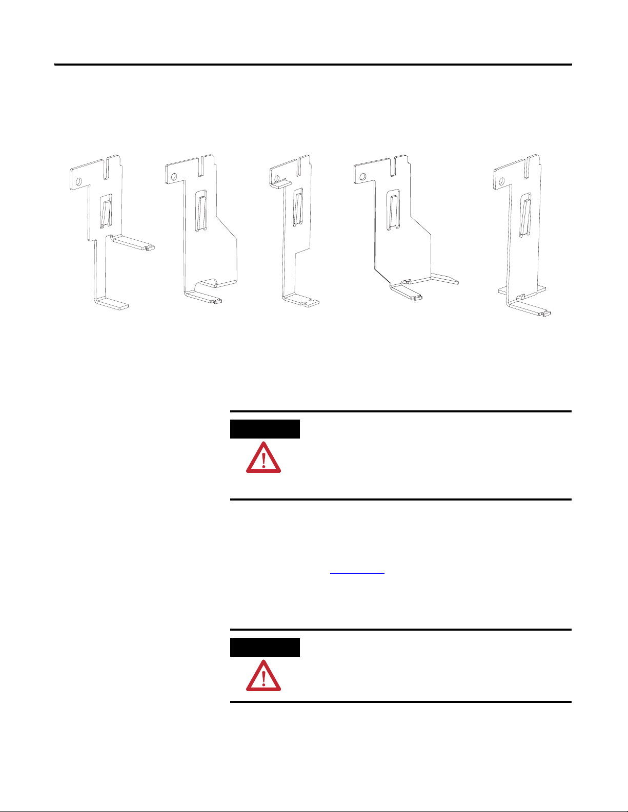
Refer to page 2
for an illustration of the interlocks.
Page 2
2 Replacing the Unit Interlock for CENTERLINE 2100 Motor Control Centers
Interlock Kit
2100H-UNTLK1
Interlock
2100H-UNTLK2
Interlock
2100H-UNTLK3 and
2100H-UNTLK4
Interlock
2100H-UNTLK5
Interlock
2100H-UNTLK6
Interlock
Replacing the Unit Interlock
Remove the Interlock from the Unit
The following sections provide information on how to remove and
install your unit interlock after removing the unit from the
CENTERLINE 2100 Motor Control Center (MCC).
ATTENTION
When working on or near energized electrical equipment, follow
established electrical safety-related work practices. Refer to NFPA
70E Standard for Electrical Safety in the Workplace.
We recommend that maintenance performed on the MCC units be
performed away from the MCC in a suitable work area.
Follow this procedure to remove the interlock from the unit. Refer to
the CENTERLINE 2100 Low Voltage Motor Control Centers Instruction
Manual, publication 2100-IN012
, for information on removing power
and removing the unit from the MCC.
1. Remove power from the unit.
ATTENTION
To prevent personal injury or damage to equipment, make sure the
unit handle is in the OFF/O position before removing the unit. Serious
injury or death can result from working on energized MCCs.
Publication 2100-IN068A-EN-P - July 2009
Page 3
Replacing the Unit Interlock for CENTERLINE 2100 Motor Control Centers 3
2. Remove the unit from the MCC.
ATTENTION
Plug-in MCC units may be heavy or awkward to handle. Use an
assistant or a platform lift device if necessary to help you handle the
unit.
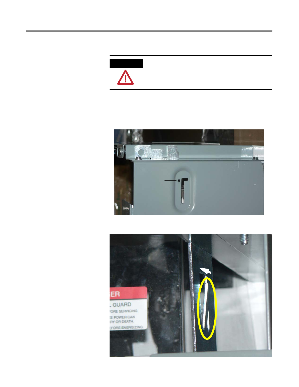
3. Loosen the taptight on the side of the unit, if used, to be able to
remove the interlock from the unit.
A taptight is not required for units that use interlock kit numbers
2100H-UNTLK3 and 2100H-UNTLK4.
Taptight Location
(if used)
4. Compress the tab on the interlock to make the tab flush with the
rest of the interlock.
Interlock Tab
Interlock
Publication 2100-IN068A-EN-P - July 2009
Page 4

4 Replacing the Unit Interlock for CENTERLINE 2100 Motor Control Centers
5. Slide the interlock up until the bottom of the interlock can be
removed from the slot in the side of the operator handle
assembly.
6. Tilt the bottom of the interlock towards the center of the unit.
Interlock
Slot
7. If you have kit numbers 2100H-UNTLK3 and 2100H-UNTLK4,
pull the interlock through the slot on the top of the unit as
shown. For the other units, pull the interlock down to remove it
from the unit.
Publication 2100-IN068A-EN-P - July 2009
Page 5

Replacing the Unit Interlock for CENTERLINE 2100 Motor Control Centers 5
Install the Interlock in the Unit
Follow this procedure to install the unit interlock.
1. Compress the tab on the interlock to make the tab flush with the
rest of the interlock.
Tab Location (for interlock kit number 2100H-UNTLK3)
2. If you have kit numbers 2100H-UNTLK3 and 2100H-UNTLK4,
push the interlock down through the slot on the top of the unit
as shown. For the other units, push the interlock up and through
the top slot to insert it into the unit.
Publication 2100-IN068A-EN-P - July 2009
Page 6

6 Replacing the Unit Interlock for CENTERLINE 2100 Motor Control Centers
3. Move the interlock, if necessary, until the bottom of the interlock
can be inserted into the slot in the side of the operator handle
assembly.
It may be necessary to manipulate the interlock up and down to
position it into the slot. Make sure the tab on the interlock is not
bent away from the interlock. This could affect the interlock
being placed into the slot. In addition, make sure that the
interlock is not caught behind the handle linkage.
4. Slide the interlock down to the bottom of the slot.
Interlock
Slot
Handle
Linkage
5. Move the handle to the ON and OFF position to help ensure that
the interlock is functioning properly.
Refer to the CENTERLINE 2100 Low Voltage Motor Control
Centers Instruction Manual, publication 2100-IN012
, for
information regarding unit interlock functionality.
6. Uncompress the tab on the interlock to the approximate
thickness of the interlock.
Publication 2100-IN068A-EN-P - July 2009
Interlock Tab
7. Tighten the taptight on the side of the unit, if used.
Page 7

Replacing the Unit Interlock for CENTERLINE 2100 Motor Control Centers 7
8. Install the unit into the MCC.
ATTENTION
To prevent personal injury or damage to equipment, make sure the
unit handle is in the OFF/O position before installing the unit. Serious
injury or death can result from working on energized MCCs.
Refer to the CENTERLINE 2100 Low Voltage Motor Control
Centers Instruction Manual, publication 2100-IN012
, for
information regarding installing units with vertical operating
handles.
ATTENTION
Plug-in MCC units may be heavy or awkward to handle. Use an
assistant or a platform lift device if necessary to help you handle the
unit.
9. Apply power to the MCC.
Refer to the CENTERLINE 2100 Low Voltage Motor Control
Centers Instruction Manual, publication 2100-IN012
, for
information for applying power.
Additional Resources
These documents contain additional information concerning MCC
products.
Resource Description
CENTERLINE 2100 Low Voltage Motor
Control Centers Instruction Manual,
publication 2100-IN012
CENTERLINE 2100 Motor Control Center
(MCC) Units with Vertical Operating
Handles Installation Instructions,
publication 2100-IN014
Provides information on installing and using
the CENTERLINE 2100 Motor Control
Center.
Provides information on installing the
CENTERLINE 2100 Motor Control Center
with vertical operating handles.
You can view or download publications at
http://literature.rockwellautomation.com. To order paper copies of
technical documentation, contact your local Rockwell Automation
distributor or sales representative.
Publication 2100-IN068A-EN-P - July 2009
Page 8

Rockwell Automation Support
Rockwell Automation provides technical information on the Web to assist you in using its products. At
http://support.rockwellautomation.com
application notes, sample code and links to software service packs, and a MySupport feature that you can customize
to make the best use of these tools.
For an additional level of technical phone support for installation, configuration, and troubleshooting, we offer
TechConnect support programs. For more information, contact your local distributor or Rockwell Automation
representative, or visit http://support.rockwellautomation.com
Installation Assistance
If you experience a problem within the first 24 hours of installation, please review the information that's contained in
this manual. You can also contact a special Customer Support number for initial help in getting your product up and
running.
United States 1.440.646.3434
Monday – Friday, 8 a.m. – 5 p.m. EST
Outside United States Please contact your local Rockwell Automation representative for any technical support issues.
, you can find technical manuals, a knowledge base of FAQs, technical and
.
New Product Satisfaction Return
Rockwell Automation tests all of its products to ensure that they are fully operational when shipped from the
manufacturing facility. However, if your product is not functioning and needs to be returned, follow these
procedures.
United States Contact your distributor. You must provide a Customer Support case number (call the phone
number above to obtain one) to your distributor to complete the return process.
Outside United States Please contact your local Rockwell Automation representative for the return procedure.
CENTERLINE, CENTERLINE 2100, Allen-Bradley, Rockwell Automation, and TechConnect are trademarks of Rockwell Automation, Inc.
Trademarks not belonging to Rockwell Automation are property of their respective companies.
Publication 2100-IN068A-EN-P - July 2009 8 PN-51577
Copyright © 2009 Rockwell Automation, In c. All rights reserved. Printed in the U.S.A.
 Loading...