

Page 1

DeviceNet To
SCANport
Communication
Module with
Digital Inputs
Catalog Number 2100-GK61
Firmware 2.xxx
User Manual
Page 2

Important User Information Because of the variety of uses for the products described in this
publication, those responsible for the application and use of this
control equipment must satisfy themselves that all necessary steps
have been taken to assure that each application and use meets all
performance and safety requirements, including any applicable laws,
regulations, codes, and standards.
The illustrations, charts, sample programs, and layout examples
shown in this guide are intended solely for purposes of example.
Since there are many variables and requirements associated with any
particular installation, Rockwell Automation does not assume
responsibility or liability (to include intellectual property liability) for
actual use based upon the examples shown in this publication.
Rockwell Automation publication SGI-1.1, Safety Guidelines for the
Application, Installation, and Maintenance of Solid-State Control
(available from your local Rockwell Automation office), describes
some important differences between solid-state equipment and
electromechanical devices that should be taken into consideration
when applying products such as those described in this publication.
Reproduction of the contents of this copyrighted publication, in
whole or in part, without written permission of Rockwell
Automation, is prohibited.
Throughout this manual we use notes to make you aware of safety
considerations:
ATTENTION: Identifies information about practices
or circumstances that can lead to personal injury or
!
Attention statements help you to:
• Identify a hazard.
• Avoid the hazard.
• Recognize the consequences.
IMPORTANT: Identifies information that is critical for successful
application and understanding of the product.
death, property damage, or economic loss.
Publication 2100-UM001B-EN-P – January 2001
Page 3

Preface
Using this Manual
Objectives Read this preface to become familiar with the organization of the
manual. In this preface, you will read about the following:
• Who should use this manual.
• An overview of the DeviceNet to SCANport Communication
Module with Digital Inputs.
• The purpose of this manual.
• Terms and abbreviations.
• Conventions used in this manual.
• Rockwell Automation support.
Who Should Use this Manual? Use this manual if you are responsible for installing, wiring,
programming, or troubleshooting control systems that use th e
DeviceNet to SCANport Communication Module with Digital Inputs.
This manual is intended for qualified service personnel responsible
for setting up and servicing the DeviceNet to SCANport
Communication Module with Digital Inputs. You must have previous
experience with and a basic understanding of electrical terminology,
programming procedures, networking, required equipment and
software, and safety precautions.
Purpose of this Manual This manual is a learning and reference guide for the DeviceNet to
SCANport Communication Module with Digital Inputs. It describes
the procedures needed to install, configure, and troubleshoot th e
adapter.
Related Publications
Title Publication Number
1771-SDN Scanner Configuration Manual 1771-6.5.118
DeviceNet Scanner Configuration Manual 1747-6.5.2
DeviceNet Cable System Planning and Installation
Manual
DN-6.7.2
Publication 2100-UM001B-EN-P – January 2001
Page 4

P-2 Using this Manual
Safety Precautions Please read the following safety precautions carefully.
ATTENTION: Only personnel familiar with
SCANport products and associated machinery should
!
plan or implement the installation, start-up,
configuration, and subsequent maintenance of the
DeviceNet to SCANport Communication Module with
Digital Inputs. Failure to comply may result in personal
injury and/or equipment damage.
Terms and Abbreviations The following terms and abbreviations are specific to this product.
For a complete listing of Allen-Bradley terminology, refer to the
Allen-Bradley Industrial Automation Glossary, Publication AG-7.1.
Terms Definition
DeviceNet An open network that provides probabilistic I/O control
through a managed bit-wise non-destructive multiplexing
scheme.
SCANport A standard peripheral communications interface for various
Allen-Bradley drives and power products.
SCANport
Peripheral
SCANport
Product
Digital Input ON-OFF input voltages of 230Vac, 115Vac, or
RSNetWorx,
RSLinx,
RSLogix,
RSLogix500
A device that provides an interface between SCANport and
a network. It is often referred to as an adapter. For example,
the DeviceNet to SCANport Communication Module with
Digital Inputs is a SCANport peripheral.
A device that uses the SCANport communications interface
to communicate with one or more peripheral devices. For
example, a motor drive such as a 1336 PLUS is a SCANport
product.
24Vdc.
Rockwell Software products which provide communication to
a wide range of applications. Refer to
http://www.software.rockwell.com for more information.
Publication 2100-UM001B-EN-P – January 2001
Page 5

Using this Manual P-3
Conventions Used in this
The following conventions are used throughout this manual:
Manual
• Bulleted lists provide information, not procedural steps.
• Numbered lists provide sequential steps or hierarchical
information.
• Italic type is used for chapter names and for parameter names.
• Bold type is used for names of menus, menu options, screens, and
dialog boxes.
Important: This type of paragraph contains tips or notes that have
been added to call attention to useful information.
Rockwell Automation Support Rockwell Automation offers support services worldwide, with more
than 75 sales/support offices, more than 500 authorized distributors,
and more than 250 authorized systems integrators located throughout
the United States alone. In addition, Rockwell Automation
representatives are in every major country in the world.
Local Product Support
Contact your local Rockwell Automation representative for:
• Sales and order support.
• Product technical training.
• Warranty support.
• Support service agreements.
Technical Product Support
If you need to contact Rockwell Automation for technical assistance,
please call your local Rockwell Automation representative.
Publication 2100-UM001B-EN-P – January 2001
Page 6

P-4 Using this Manual
Publication 2100-UM001B-EN-P – January 2001
Page 7

Table of Contents
Important User Information . . . . . . . . . . . . . . . . . . . . . . . . . . .2
Using this Manual Objectives . . . . . . . . . . . . . . . . . . . . . . . . . . . . . . . . . . . . . .P-1
Who Should Use this Manual? . . . . . . . . . . . . . . . . . . . . . .P-1
Purpose of this Manual. . . . . . . . . . . . . . . . . . . . . . . . . . . . .P-1
Related Publications . . . . . . . . . . . . . . . . . . . . . . . . . . . . P-1
Safety Precautions . . . . . . . . . . . . . . . . . . . . . . . . . . . . . . .P-2
Terms and Abbreviations . . . . . . . . . . . . . . . . . . . . . . . . . . .P-2
Conventions Used in this Manual. . . . . . . . . . . . . . . . . . . . P-3
Rockwell Automation Support . . . . . . . . . . . . . . . . . . . . . . P-3
Local Product Support. . . . . . . . . . . . . . . . . . . . . . . . . . . .P-3
Technical Product Support . . . . . . . . . . . . . . . . . . . . . . . .P-3
Chapter 1
Overview Chapter Objectives . . . . . . . . . . . . . . . . . . . . . . . . . . . . . . . 1-1
Overview of the Communication Adapter. . . . . . . . . . . . . . 1-1
Features of the Communication Adapter . . . . . . . . . . . . . . 1-3
SCANport Products . . . . . . . . . . . . . . . . . . . . . . . . . . . . . . . 1-5
Hardware and Parts Description . . . . . . . . . . . . . . . . . . . . . 1-6
2100-GK61 Module Hardware . . . . . . . . . . . . . . . . . . . . . 1-6
Overview of Setting Up the Adapter. . . . . . . . . . . . . . . . . . 1-7
Required Tools and Equipment . . . . . . . . . . . . . . . . . . . . . . 1-7
Chapter 2
Installation Chapter Objectives . . . . . . . . . . . . . . . . . . . . . . . . . . . . . . . 2-1
Installing a 2100-GK61 Module . . . . . . . . . . . . . . . . . . . . . .2-1
Required Tools and Equipment. . . . . . . . . . . . . . . . . . . . 2-1
Selecting Cables . . . . . . . . . . . . . . . . . . . . . . . . . . . . . . .2-1
Installing the DeviceNet to SCANport Communication
Module with Digital Inputs (2100-GK61). . . . . . . . . . . 2-3
Removing the DeviceNet to SCANport Communication
Module with Digital Inputs (2100-GK61). . . . . . . . . . 2-10
Chapter 3
Configuring the DeviceNet to
SCANport Communication Module
with Digital Inputs
Configuring a Scanner to Communicate with the Adapter
Chapter Objectives. . . . . . . . . . . . . . . . . . . . . . . . . . . . . . . 3-1
Factory Default Settings for the 2100-GK61. . . . . . . . . . . . . 3-1
What is RSNetWorx for DeviceNet? . . . . . . . . . . . . . . . . . . 3-2
Required Equipment and Software. . . . . . . . . . . . . . . . . . . . 3-2
Using RSNetWorx to Edit Your Adapter’s Parameters. . . . 3-3
Chapter 4
Chapter Objectives . . . . . . . . . . . . . . . . . . . . . . . . . . . . . . . 4-1
What is RSNetWorx for DeviceNet?. . . . . . . . . . . . . . . . . . 4-1
Required Equipment and Software. . . . . . . . . . . . . . . . . . . . 4-1
Getting Started . . . . . . . . . . . . . . . . . . . . . . . . . . . . . . . . . .4-2
Using Online Mode in RSNetWorx for DeviceNet . . . . . . . . 4-2
Downloading an EDS File for Your SCANport Product . . . . 4-4
Configuring a Scanner . . . . . . . . . . . . . . . . . . . . . . . . . 4-15
Configuring a PLC Scanner (1771-SDN) to Communicate
with the Adapter. . . . . . . . . . . . . . . . . . . . . . . . . . . . . . . 4-15
Configuring an SLC Scanner (1747-SDN) to Communicate
with the Adapter . . . . . . . . . . . . . . . . . . . . . . . . . . . . . . . 4-23
Configuring an SLC Scanner . . . . . . . . . . . . . . . . . . . . 4-23
Configuring a ControlLogix Scanner (1756-DNB) to
Communicate with the Adapter. . . . . . . . . . . . . . . . . . . . 4-30
Page 8

Chapter 5
Ladder Logic Programming Including Reading Inputs
Chapter Objectives. . . . . . . . . . . . . . . . . . . . . . . . . . . . . . . .5-1
Required Equipment. . . . . . . . . . . . . . . . . . . . . . . . . . . . . . 5-1
What is RSLogix?. . . . . . . . . . . . . . . . . . . . . . . . . . . . . . . . .5-2
What are Ladder Logic Programs?. . . . . . . . . . . . . . . . . . . 5-3
Example Ladder Logic Programs . . . . . . . . . . . . . . . . . . . . 5-4
PLC Ladder Logic Example . . . . . . . . . . . . . . . . . . . . . . . 5-7
SLC Ladder Logic Program Example . . . . . . . . . . . . . . 5-11
ControlLogix Programming Example . . . . . . . . . . . . . . . . 5-15
Chapter 6
Using DeviceNet Explicit
Messaging
Chapter Objectives. . . . . . . . . . . . . . . . . . . . . . . . . . . . . . . 6-1
Required Equipment . . . . . . . . . . . . . . . . . . . . . . . . . . . . . . 6-1
Explicit Message Program Control for PLC-5 . . . . . . . . . . . 6-1
Message Translations . . . . . . . . . . . . . . . . . . . . . . . . . . . . .6-3
Messaging for the 1771-SDN Scanner. . . . . . . . . . . . . . . . . 6-3
Examples . . . . . . . . . . . . . . . . . . . . . . . . . . . . . . . . . . . . . . . 6-6
PLC-5 Ladder Example . . . . . . . . . . . . . . . . . . . . . . . . . . . . 6-6
PLC Messaging. . . . . . . . . . . . . . . . . . . . . . . . . . . . . . . . .6-6
Explicit Messaging Programming Example . . . . . . . . . . . . 6-10
Example Ladder Program Explanation . . . . . . . . . . . . . . . 6-10
Explicit Message Program Control for SLC . . . . . . . . . . . .6-15
Message Translations. . . . . . . . . . . . . . . . . . . . . . . . . . . . 6-16
Examples . . . . . . . . . . . . . . . . . . . . . . . . . . . . . . . . . . . . . . 6-16
Messaging for the 1747-SDN Scanner . . . . . . . . . . . . . . . 6-16
SLC Ladder Example . . . . . . . . . . . . . . . . . . . . . . . . . . . . .6-19
SLC Messaging. . . . . . . . . . . . . . . . . . . . . . . . . . . . . . . .6-19
Using Messages to Control SCANport Products . . . . . . . .6-21
Writing to Register Objects. . . . . . . . . . . . . . . . . . . . . . . . . 6-22
Reading Values from DeviceNet Using Explicit Messaging
and ControlLogix . . . . . . . . . . . . . . . . . . . . . . . . . . . . . .6-23
Configure the I/0 . . . . . . . . . . . . . . . . . . . . . . . . . . . . . . .6-23
Chapter 7
Troubleshooting Chapter Objectives . . . . . . . . . . . . . . . . . . . . . . . . . . . . . . .7-1
LEDs on the 2100-GK61 Module . . . . . . . . . . . . . . . . . . . . .7-1
DeviceNet Network Status LED States . . . . . . . . . . . . . . . .7-2
Module Status LED States . . . . . . . . . . . . . . . . . . . . . . . . . .7-2
SCANport Status LED States . . . . . . . . . . . . . . . . . . . . . . .7-3
Input Status LED States . . . . . . . . . . . . . . . . . . . . . . . . . . . 7-4
Product Specifications Appendix Objectives. . . . . . . . . . . . . . . . . . . . . . . . . . . . . . A-1
2100-GK61 Specifications . . . . . . . . . . . . . . . . . . . . . . . . . .A-1
DeviceNet to SCANport Communication Module with Digital Inputs
Parameters
Appendix Objectives. . . . . . . . . . . . . . . . . . . . . . . . . . . . . . B-1
Setting the Node Address. . . . . . . . . . . . . . . . . . . . . . . . . . B-1
Setting the Data Rate . . . . . . . . . . . . . . . . . . . . . . . . . . . . .B-2
Using Datalinks and Command I/O . . . . . . . . . . . . . . . . . . .B-3
Using Master-Slave Communications. . . . . . . . . . . . . . . . . .B-5
Polled Allocation . . . . . . . . . . . . . . . . . . . . . . . . . . . . . . . .B-5
COS (Change of State) Allocation. . . . . . . . . . . . . . . . . . B-7
Cyclic Allocation . . . . . . . . . . . . . . . . . . . . . . . . . . . . . . . .B-8
Polled and COS Allocation . . . . . . . . . . . . . . . . . . . . . . B-10
Polled and Cyclic Allocation . . . . . . . . . . . . . . . . . . . . . .B-11
Using Peer-to-Peer Communications . . . . . . . . . . . . . . . .B-12
Enabling the Adapter to Receive Peer I/O . . . . . . . . . . .B-13
Enabling the Adapter to Transmit Peer I/O . . . . . . . . . .B-15
Using Fault Configurable Inputs . . . . . . . . . . . . . . . . . . . .B-16
Page 9

DeviceNet to SCANport Communication Module
with Digital Inputs Parameters . . . . . . . . . . . . . . . . . . . .B-17
M-S Input Parameter Configurations . . . . . . . . . . . . . . .B-24
M-S Output Parameter Configurations . . . . . . . . . . . . . .B-26
DeviceNet Objects Appendix Objectives . . . . . . . . . . . . . . . . . . . . . . . . . . . . . .C-1
Object Classes . . . . . . . . . . . . . . . . . . . . . . . . . . . . . . . . . .C-1
Class Code 0x01 — Identity Object . . . . . . . . . . . . . . . . . . .C-2
Class Attributes. . . . . . . . . . . . . . . . . . . . . . . . . . . . . . . . C-2
Instances. . . . . . . . . . . . . . . . . . . . . . . . . . . . . . . . . . . . . C-2
Instance Attributes . . . . . . . . . . . . . . . . . . . . . . . . . . . . . .C-3
Common Services . . . . . . . . . . . . . . . . . . . . . . . . . . . . . .C-3
Get_Attribute_All Response . . . . . . . . . . . . . . . . . . . . . . .C-3
Class Code 0x02 — Message Router Object. . . . . . . . . . . .C-4
Class Attributes. . . . . . . . . . . . . . . . . . . . . . . . . . . . . . . . C-4
Instances. . . . . . . . . . . . . . . . . . . . . . . . . . . . . . . . . . . . . .C-4
Instance Attributes . . . . . . . . . . . . . . . . . . . . . . . . . . . . . .C-4
Common Services. . . . . . . . . . . . . . . . . . . . . . . . . . . . . . .C-4
Class Code 0x03 — DeviceNet Object . . . . . . . . . . . . . . . .C-5
Class Attributes. . . . . . . . . . . . . . . . . . . . . . . . . . . . . . . . C-5
Instances . . . . . . . . . . . . . . . . . . . . . . . . . . . . . . . . . . . . .C-5
Instance Attributes . . . . . . . . . . . . . . . . . . . . . . . . . . . . . C-5
Common Services. . . . . . . . . . . . . . . . . . . . . . . . . . . . . . C-5
Class Code 0x05 — Connection . . . . . . . . . . . . . . . . . . . . C-6
Class Attributes. . . . . . . . . . . . . . . . . . . . . . . . . . . . . . . . C-6
Instances . . . . . . . . . . . . . . . . . . . . . . . . . . . . . . . . . . . . .C-6
Instance Attributes . . . . . . . . . . . . . . . . . . . . . . . . . . . . . C-7
Common Services. . . . . . . . . . . . . . . . . . . . . . . . . . . . . . C-7
Class Code 0x07 — Register Object . . . . . . . . . . . . . . . . . .C-8
Class Attributes . . . . . . . . . . . . . . . . . . . . . . . . . . . . . . . .C-8
Instances. . . . . . . . . . . . . . . . . . . . . . . . . . . . . . . . . . . . . C-8
Instance Attributes . . . . . . . . . . . . . . . . . . . . . . . . . . . . . .C-9
Common Services. . . . . . . . . . . . . . . . . . . . . . . . . . . . . . C-9
Class Code 0x0F — Parameter Object . . . . . . . . . . . . . . .C-10
Class Attributes . . . . . . . . . . . . . . . . . . . . . . . . . . . . . . .C-10
Instances. . . . . . . . . . . . . . . . . . . . . . . . . . . . . . . . . . . . C-10
Instance Attributes . . . . . . . . . . . . . . . . . . . . . . . . . . . . .C-11
Bit Definitions for Instance Attribute 4 . . . . . . . . . . . . . .C-12
Data Types for Instance Attribute 5. . . . . . . . . . . . . . . . C-13
Common Services. . . . . . . . . . . . . . . . . . . . . . . . . . . . . C-14
Get_Attribute_All Response . . . . . . . . . . . . . . . . . . . . . .C-14
Object Specific Services . . . . . . . . . . . . . . . . . . . . . . . . C-15
Class Code 0x10 — Parameter Group Object . . . . . . . . . C-16
Class Attributes . . . . . . . . . . . . . . . . . . . . . . . . . . . . . . .C-16
Instances . . . . . . . . . . . . . . . . . . . . . . . . . . . . . . . . . . . .C-16
Instance Attributes . . . . . . . . . . . . . . . . . . . . . . . . . . . . .C-16
Common Services. . . . . . . . . . . . . . . . . . . . . . . . . . . . . C-17
Get_Attribute_All Response . . . . . . . . . . . . . . . . . . . . . .C-17
Class Code 0x93 — SCANport Pass-Through . . . . . . . . .C-18
Class Attributes . . . . . . . . . . . . . . . . . . . . . . . . . . . . . . .C-18
Instance Attributes . . . . . . . . . . . . . . . . . . . . . . . . . . . . C-18
Common Services . . . . . . . . . . . . . . . . . . . . . . . . . . . . .C-18
Object-Specific Services. . . . . . . . . . . . . . . . . . . . . . . . .C-18
Class Code 0x97 — SCANport Pass-Through
Fault Object . . . . . . . . . . . . . . . . . . . . . . . . . . . . . . . . . .C-19
Class Attributes. . . . . . . . . . . . . . . . . . . . . . . . . . . . . . . .C-19
Instance Attributes . . . . . . . . . . . . . . . . . . . . . . . . . . . . .C-19
Common Services . . . . . . . . . . . . . . . . . . . . . . . . . . . . .C-20
Page 10

Class Code 0x98 — SCANport Pass-Through Warning. . C-21
Class Attributes. . . . . . . . . . . . . . . . . . . . . . . . . . . . . . . C-21
Instance Attributes. . . . . . . . . . . . . . . . . . . . . . . . . . . . . C-21
Common Services . . . . . . . . . . . . . . . . . . . . . . . . . . . . .C-22
Class Code 0x99 — SCANport Pass-Through Link Object C-23
Class Attributes. . . . . . . . . . . . . . . . . . . . . . . . . . . . . . . .C-23
Instance Attributes. . . . . . . . . . . . . . . . . . . . . . . . . . . . . .C-23
Common Services . . . . . . . . . . . . . . . . . . . . . . . . . . . . .C-23
Object-Specific Services. . . . . . . . . . . . . . . . . . . . . . . . C-23
Class Code 0x67 — PCCC Object. . . . . . . . . . . . . . . . . . .C-25
Class Attributes . . . . . . . . . . . . . . . . . . . . . . . . . . . . . . .C-25
Instance Attributes . . . . . . . . . . . . . . . . . . . . . . . . . . . . .C-25
Common Service . . . . . . . . . . . . . . . . . . . . . . . . . . . . . .C-25
Object Specific Services . . . . . . . . . . . . . . . . . . . . . . . . .C-25
Message Structure for Execute_PCCC. . . . . . . . . . . . . C-25
Message Structure for Execute_Local_PCCC . . . . . . . .C-26
N-File Addresses Appendix Objectives. . . . . . . . . . . . . . . . . . . . . . . . . . . . . . D-1
N-File Addresses . . . . . . . . . . . . . . . . . . . . . . . . . . . . . . . . D-1
Supported Emulated Block Transfer Commands
Appendix Objectives . . . . . . . . . . . . . . . . . . . . . . . . . . . . . .E-1
What is Emulated Block Transfer? . . . . . . . . . . . . . . . . . . .E-1
Supported Emulated Block Transfer Commands . . . . . . . . .E-1
Emulated Block Transfer Status Word . . . . . . . . . . . . . . . . .E-2
Parameter Value Read . . . . . . . . . . . . . . . . . . . . . . . . . . . .E-3
PLC Block Transfer Emulation Instruction Data . . . . . . . .E-3
Message Operation . . . . . . . . . . . . . . . . . . . . . . . . . . . . .E-3
Example . . . . . . . . . . . . . . . . . . . . . . . . . . . . . . . . . . . . . . E-3
Parameter Value Write . . . . . . . . . . . . . . . . . . . . . . . . . . . . .E-4
PLC Block Transfer Emulation Instruction Data . . . . . . . .E-4
Message Operation. . . . . . . . . . . . . . . . . . . . . . . . . . . . . E-4
Example . . . . . . . . . . . . . . . . . . . . . . . . . . . . . . . . . . . . . E-4
Parameter Read Full . . . . . . . . . . . . . . . . . . . . . . . . . . . . . .E-5
PLC Block Transfer Emulation Instruction Data . . . . . . . E-5
Message Operation. . . . . . . . . . . . . . . . . . . . . . . . . . . . . E-6
Example . . . . . . . . . . . . . . . . . . . . . . . . . . . . . . . . . . . . . . E-6
Product ID Number Read . . . . . . . . . . . . . . . . . . . . . . . . . .E-8
PLC Block Transfer Emulation Instruction Data . . . . . . . .E-8
Message Operation. . . . . . . . . . . . . . . . . . . . . . . . . . . . . E-9
Example . . . . . . . . . . . . . . . . . . . . . . . . . . . . . . . . . . . . . . E-9
Scattered Parameter Value Read . . . . . . . . . . . . . . . . . . .E-10
PLC Block Transfer Emulation Instruction Data . . . . . . .E-10
Message Operation . . . . . . . . . . . . . . . . . . . . . . . . . . . .E-11
Example . . . . . . . . . . . . . . . . . . . . . . . . . . . . . . . . . . . . .E-11
Scattered Parameter Value Write . . . . . . . . . . . . . . . . . . .E-12
PLC Block Transfer Emulation Instruction Data . . . . . . E-12
Message Operation. . . . . . . . . . . . . . . . . . . . . . . . . . . . E-13
Example . . . . . . . . . . . . . . . . . . . . . . . . . . . . . . . . . . . . . E-13
NVS Functions . . . . . . . . . . . . . . . . . . . . . . . . . . . . . . . . . .E-14
PLC Block Transfer Emulation Instruction Data . . . . . . E-14
Message Operation . . . . . . . . . . . . . . . . . . . . . . . . . . . .E-14
Example . . . . . . . . . . . . . . . . . . . . . . . . . . . . . . . . . . . . E-14
Fault Command Write . . . . . . . . . . . . . . . . . . . . . . . . . . . .E-15
PLC Block Transfer Emulation Instruction Data . . . . . . E-15
Message Operation. . . . . . . . . . . . . . . . . . . . . . . . . . . . .E-15
Fault Queue Entry Read Full . . . . . . . . . . . . . . . . . . . . . . E-16
PLC Block Transfer Emulation Instruction Data . . . . . . .E-16
Message Operation . . . . . . . . . . . . . . . . . . . . . . . . . . . .E-17
Example . . . . . . . . . . . . . . . . . . . . . . . . . . . . . . . . . . . . .E -17
Fault Queue Size . . . . . . . . . . . . . . . . . . . . . . . . . . . . . . . .E-18
PLC Block Transfer Emulation Instruction Data . . . . . . E-18
Message Operation. . . . . . . . . . . . . . . . . . . . . . . . . . . . .E-18
Page 11

Example . . . . . . . . . . . . . . . . . . . . . . . . . . . . . . . . . . . . E-18
Trip Fault Queue Number . . . . . . . . . . . . . . . . . . . . . . . . .E-19
PLC Block Transfer Emulation Instruction Data . . . . . . .E-19
Message Operation . . . . . . . . . . . . . . . . . . . . . . . . . . . .E-19
Example . . . . . . . . . . . . . . . . . . . . . . . . . . . . . . . . . . . . E-19
Digital Input Parameter Read. . . . . . . . . . . . . . . . . . . . . . E-20
PLC Block Transfer Emulation Instructions Data . . . . . E-20
Message Operation. . . . . . . . . . . . . . . . . . . . . . . . . . . . E-21
Example . . . . . . . . . . . . . . . . . . . . . . . . . . . . . . . . . . . . . E-21
Page 12

Page 13
Chapter 1
Overview
Chapter Objectives Chapter 1 provides an overview of your DeviceNet to SCANport
Communication module with Digital Inputs. In this chapter, you will
read about the following:
• Function of the 2100-GK61 module.
• Features of the 2100-GK61 module.
• SCANport products.
• Parts and hardware of the 2100-GK61 module.
• Steps for setting up the adapter.
• Required tools and equipment.
Overview of the
Communication Adapter
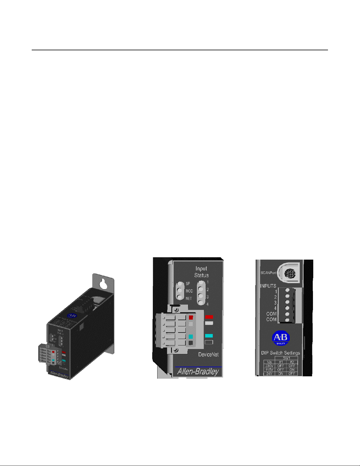
Figure 1.1
2100-GK61 Module
2100-GK61 Module
2100-GK61 Module - Front View
The 2100-GK61 module mounts on a panel and connects to the
SCANport product via a SCANport cable. Digital inputs of 230Vac,
115Vac, or 24Vdc are connected to the adapter via discrete wires. The
voltage level used for the digital inputs is set via a dip switch SW1.
2100-GK61 Module - Top View
Publication 2100-UM001B-EN-P – January 2001
Page 14
1-2 Overview
The communications adapter provides an electronic communications
interface between a DeviceNet network and any single SCANport
product.
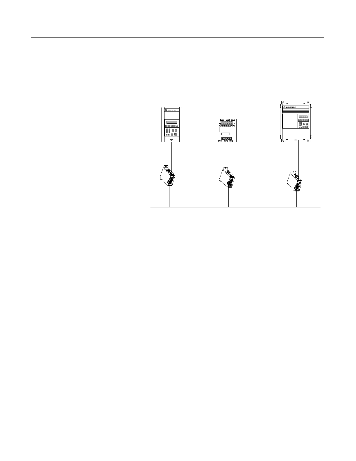
Figure 1.2
Example of 2100-GK61 Modules Connecting SCANport Produ ct s
to DeviceNet
1336 PLUS
1305
SMC Dialog Plus
DeviceNet
In Figure 1.2, a SCANport cable connects a 2100-GK61 module to a
SCANport product through a port on the SCANport product. A
DeviceNet cable co nn ec ts the module to the DeviceNet network. The
module then translates the DeviceNet messages into SCANport
messages that can be understood by the connected product.
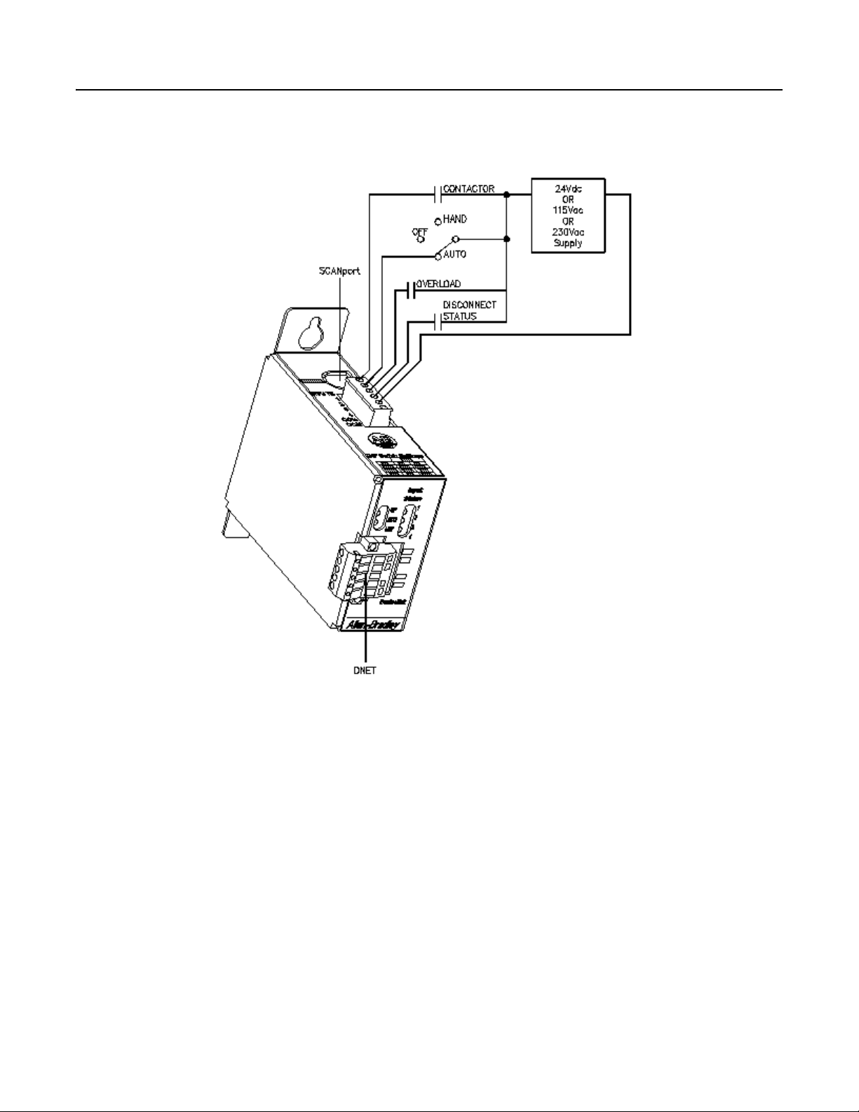
The adapter is also capable of connecting to four (4) common switch
inputs. These inputs can monitor status of disconnect switches, starter
and contactor auxiliary contact, relays, push buttons, or any ON-OFF
device capable of switching 230Vac, 115Vac, or 24Vdc.
Publication 2100-UM001B-EN-P – January 2001
Page 15
Overview 1-3
Figure 1.3
Example of 2100-GK61 Module Connecting Digital Inputs
Features of the Communication
Adapter
In Figure 1.3, discrete wiring connects up to four (4) digital inputs to
the 2100-GK61 module. A DeviceNet cable connects the module to
the DeviceNet network and a SCANport cable connects a SCANport
product to the module. The contact status is then translated into a
DeviceNet message that can be used to control SCANport devices
attached to the module or other devices on the DeviceNet network.
The DeviceNet network is an open, global industry-standard
communication network designed to provide an interface through a
single cable from a programmable controller directly to “smart”
devices such as sensors, push buttons, motor starters, simple operator
interfaces, and drives.
The 2100-GK61 module lets you connect your SCANport products to
a DeviceNet network. This adapter features the following:
• Flash upgradeability allows for field updates in the event of
changes to the adapter’s firmware.
Publication 2100-UM001B-EN-P – January 2001
Page 16

1-4 Overview
• COS (Change of State) capability lets you customize this device’ s
activity on the network by configuring the adapter to report only
new data.
• Cyclic operation lets you customize the devices’s activity on the
network by configuring the adapter to report its data at specific
intervals.
• Polled operation allows you to customize the device’s activity on
the network to respond only after the scanner sends control data.
• Peer I/O capabilities let the drive’s I/O (logic command,
reference, logic status, feedback and datalinks) be broadcast to or
received from other drives connected via 1203-GU6, 1336-GM6
or 2100-GK61 adapters.
• Software configuration lets you configure the adapter using
RSNetWorx for DeviceNet.
• Faulted Node Recovery lets you change an item, such as a node
address of a device, even when it is faulted on the network.
• User-configurable fault response pro vides the ability to customize
the adapter’s actions to communication errors.
• A Module Status LED helps to diagnose network, module, and
SCANport product health.
• Monitor and report status of four (4) individual digital inputs.
Publication 2100-UM001B-EN-P – January 2001
Page 17

Overview 1-5
SCANport Products Some SCANport products support one peripheral; others support up
to six peripherals. The table below lists SCANport products, the
number of peripherals each supports, the minimum and maximum I/O
words, and the type of adapter that can be used.
Number of
Product
1305 AC MICRO Drive 5 0 10 Yes
1336 IMPACT™ Drive 6
1336 PLUS AC Drive 6
1336 PLUS II Drive 6
1336 FORCE™ Drive 6
1394 AC Mult-Axis Motion
Control System
SMC Dialog Plus 1 0 2 Yes
SMP-3 Smart Motor Protector 2 0 2 Yes
1397 Digital DC Drive 5 0 10 Yes
1557 Medium Voltage Drive 5 0 10 Yes
➀ Lower horsepower products may not support a sixth peripheral. Refer to your user manual to verify that your
product supports a sixth peripheral.
Peripherals
Supported
➀ 010Yes
➀ 010Yes
➀ 010Yes
➀ 010Yes
5010Yes
I/O Words Adapter Use
Minimum Maximum 2100-GK61
Important: To connect multiple peripherals to a SCANport product,
a port expander may be required. Refer to your product’s
documentation for more information.
Important: If you intend to use datalinks to communicate with and
control your SCANport product, verify that your SCANport product
supports datalinks before enabling them in the adapter.
Publication 2100-UM001B-EN-P – January 2001
Page 18
1-6 Overview
Hardware and Parts
Description
2100-GK61 Module Hardware
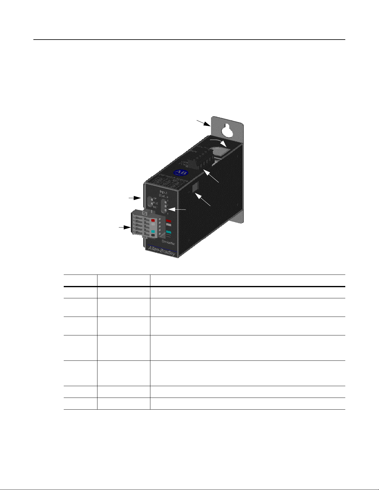
Figure 1.4 illustrates and the following table lists the main parts of the
2100-GK61 DeviceNet to SCANport communication module with
Digital Inputs:
Figure 1.4
Parts of the 2100-GK61 Module
1
2
3
4
6
7
5
Number Part Description
1 Panel mount Attach module to sub-panel through mounting holes.
2 SCANport
Connection
3 Digital Input
Connector
4 Bi-Color LEDs Indicate the status of the DeviceNet media channel, of the SCANport con-
5 DeviceNet Con-
nection
6 Input Status LEDs Indicate the ON-OFF status of the digital inputs.
7 SW1 Set to match the digital input voltage applied of 230Vac, 115Vac, or 24Vdc.
Provides a standard SCANport 8-pin circular mini-DIN connector for the
SCANport cable.
Allows connection of switched 230Vac, 115Vac, or 24Vdc inputs to module.
The 6-pin plug-in connector (PIN 192 929) is supplied with the module.
nection, and of the module. For more information, refer to Chapter 7, Trou-
bleshooting.
Provides a 10-pin Phoenix connector to attach the module to the DeviceNet
network. The 10-pin plug-in connector (PIN 94220605) is supplied with the
module.
Publication 2100-UM001B-EN-P – January 2001
Page 19

Overview 1-7
Overview of Setting Up the
Adapter
To set up the DeviceNet to SCANport Communication Module with
Digital Inputs, you must perform the following tasks:
1. Install the module. Refer to Chapter 2, Installation.
2. Set the adapter’s node address and configure the adapter’s
parameters. Refer to Chapter 3, Configuring the DeviceNet to
SCANport Communication Module with Digital Inputs.
3. Configure a scanner (either PLC or SLC) to communicate with
the Adapter. Refer to Chapter 4 , Configuring a Scanner to
Communicate with the Adapter.
4. If necessary, create a ladder logic program to control the
SCANport product. Refer to Chapter 5, Ladder Logic
Programming—Including Reading Inputs.
Required Tools and Equipment To install and configure a 2100-GK61 module, you need the
following:
• DeviceNet to SCANport Communication Module with Digital
Inputs (2100-GK61).
• 10-pin plug-in DeviceNet connector (supplied with module).
• Appropriate cables for SCANport and DeviceNet connections.
Refer to the Selecting Cables section in Chapter 2, Installation.
• 6-pin plug-in Input connector (supplied with module).
• #10 hardware for attaching module to a panel.
• A PC that is:
– Running RSNetWorx.
– Connected to and communicating with the DeviceNet
network using a 1784-PCD card or a 1770-KFD adapter.
– Running RS Linx.
– Running RSLogix5 (if using PLC) or RSLogix500 (if using
SLC).
Important: Refer to http://www.software.rockwell.com for more
information on these software products.
Publication 2100-UM001B-EN-P – January 2001
Page 20

1-8 Overview
Publication 2100-UM001B-EN-P – January 2001
Page 21

Chapter 2
Installation
Chapter Objectives Chapter 2 provides the information that you need to install the
2100-GK61 module. In this chapter, you will read about the
following:
• Required tools and equipment.
• Selecting cables.
• Installing the adapter.
• Removing the adapter.
Installing a 2100-GK61 Module Follow these procedures to install a 2100-GK61 module.
Required Tools and Equipment
To install your 2100-GK61 module, you will need the following tools
and equipment:
• DeviceNet to SCANport Communication Module with Digital
Inputs(2100-GK61).
• A 6-pin and 10-pin plug-in connector (supplied with module).
• Screwdriver or nutdriver and mounting screws (#10).
• Appropriate cables for SCANport and DeviceNet connections.
Refer to the “Selecting Cables” section below.
Selecting Cables
To connect the 2100-GK61 to the SCANport product and the
DeviceNet network, you must select an appropriate DeviceNet cable
and Allen-Bradley SCANport cable. Use the following information to
select appropriate cables for each connection.
Publication 2100-UM001B-EN-P – January 2001
Page 22

2-2 Installation
SCANport Cables
When selecting the SCANport cable to connect the 2100-GK61
module to the SCANport product, you need to:
• Use an Allen-Bradley SCANport cable. Refer to the table below.
Male to Male Connection Male to Female Connection
Length Catalog Number Length Catalog Number
1/3 m 1202-C03 1/3 m 1202-H03
1 m 1202-C10 1 m 1 202-H10
3 m 1202-C30 3 m 1 202-H30
9 m 1202-C90 9 m 1 202-H90
• Use less than 10 meters (33 feet) of cable between the SCANport
product and adapter.
• Keep SCANport cables away from high power cables to guard
against introducing noise into your system.
DeviceNet Cables
The 2100-GK61 module comes with a 10-pin (dual row 5-pin)
connector. This connector is used to wire the module for both single
drops, when only one side of each terminal is used, or to daisy chain
devices together when both sides of the terminals are used. A drop
line connects a node such as a 2100-GK61 module in the DeviceNet
cable system to the DeviceNet trunk.
Before connecting modules to the network, you must determine if
your network is within limits of the cable system. Class 1 cables are
rated 600 volts, 8 amps. Class 2 cables are rated 300 volts, 4 amps.
The cables in the chart below can be used for Trunk or Drop
applications. When used for Trunk, length limits must be observed.
Cable Type Part Number Dat a Rates
125 Kbps 250 Kbps 500 Kbps
Class 1 Flat 1485C-P1-E75 420m (1378 ft.) 200m (656 ft.) 75m (246 ft.)
Class 2 Thick Round 1485C-P1-A50 500m (1640 ft.) 250m (820 ft.) 100m (328 ft.)
Class 2 Thin Round 1485C-P1-C50 100m (328 ft.) 100m (328 ft.) 100m (328 ft.)
Publication 2100-UM001B-EN-P – January 2001
Class 1 round drop cable is recommended for connections between
devices and Class 1 Trunk. Maximum drop length is 6m (20 ft.)
Cumulative Drop Budget is based on Data Rate.
125 Kbps 250 Kbps 500 Kbps
156m (512 ft.) 78m (256 ft.) 39m (128 ft.)
Page 23

Installation 2-3
Class 1 Drop Cable is available in three spool sizes:
Cable Part Number Spool Size
1485C-P1-B50 50m (164 ft.)
1485C-P1-B150 150m (492 ft.)
1485C-P1-B300 300m (984 ft.)
For more information on DeviceNet cables and cable systems, refer to
the DeviceNet Cable System Planning and Installation Manual,
Publication DN-6.7.2.
Input Wires
Choose a suitable wire to handle 230Vac, 115Vac, or 24Vdc voltage,
depending on installation. The input connector is capable of installing
12-24AWG wire.
Installing the DeviceNet to SCANport Communication
Module with Digital Inputs (2100-GK61)
The following instructions explain how to physically install your
DeviceNet to SCANport Communication Module with Digital Inputs.
ATTENTION: Severe injury or death can result from
electrical shock, burn, or unintended actuation of controlled
!
equipment. Hazardous volta ges may exist in the cabinet even
with the circuit breaker in the off position. Recommended
practice is to disconnect and lock out control equipment from
power sources and discharge stored ener g y in capacitors, if
present. If it is necessary to work in the vicinity of energized
equipment, the safety related work practices of NFPA 70E,
Electrical Safety Requirements for Employee Workplaces,
must be followed.
ATTENTION: DO NOT work alone on energized
equipment!
1. Before installing the module, set the Digital Input selection
switch SW1 to the proper input voltage per the table below.
VIN
#1 #2
230Vac OFF OFF
SW1
115Vac OFF ON
24Vdc ON OFF
Publication 2100-UM001B-EN-P – January 2001
Page 24

2-4 Installation
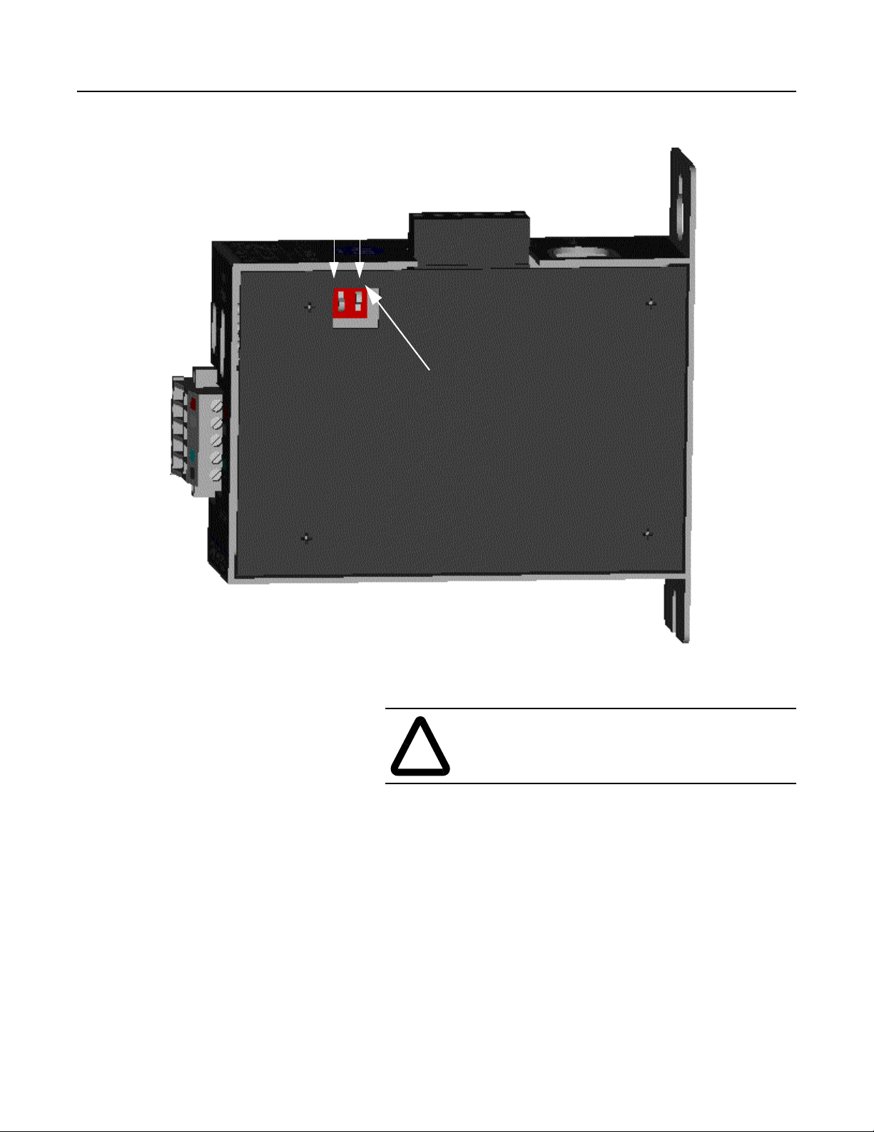
SW1 is accessed through the plastic cover on the 2100-GK61
module as show in Figure 2.1
ATTENTION: To guard against possible
component damage, assure that Dip Switch
!
SW1 is set for the correct input voltage used
in the system before power is applied to the
module.
Publication 2100-UM001B-EN-P – January 2001
Page 25
Installation 2-5
Figure 2.1
Dip Switch Access - Side View of 2100-GK61 Module
1
2
Dip Switch Location
2. Determine a suitable mounting location within a desired location
close to its interconnecting devices and /or components.
A TTENTION: The 2100-GK61 module is an open
panel device and must be mounted inside a suitabl e
!
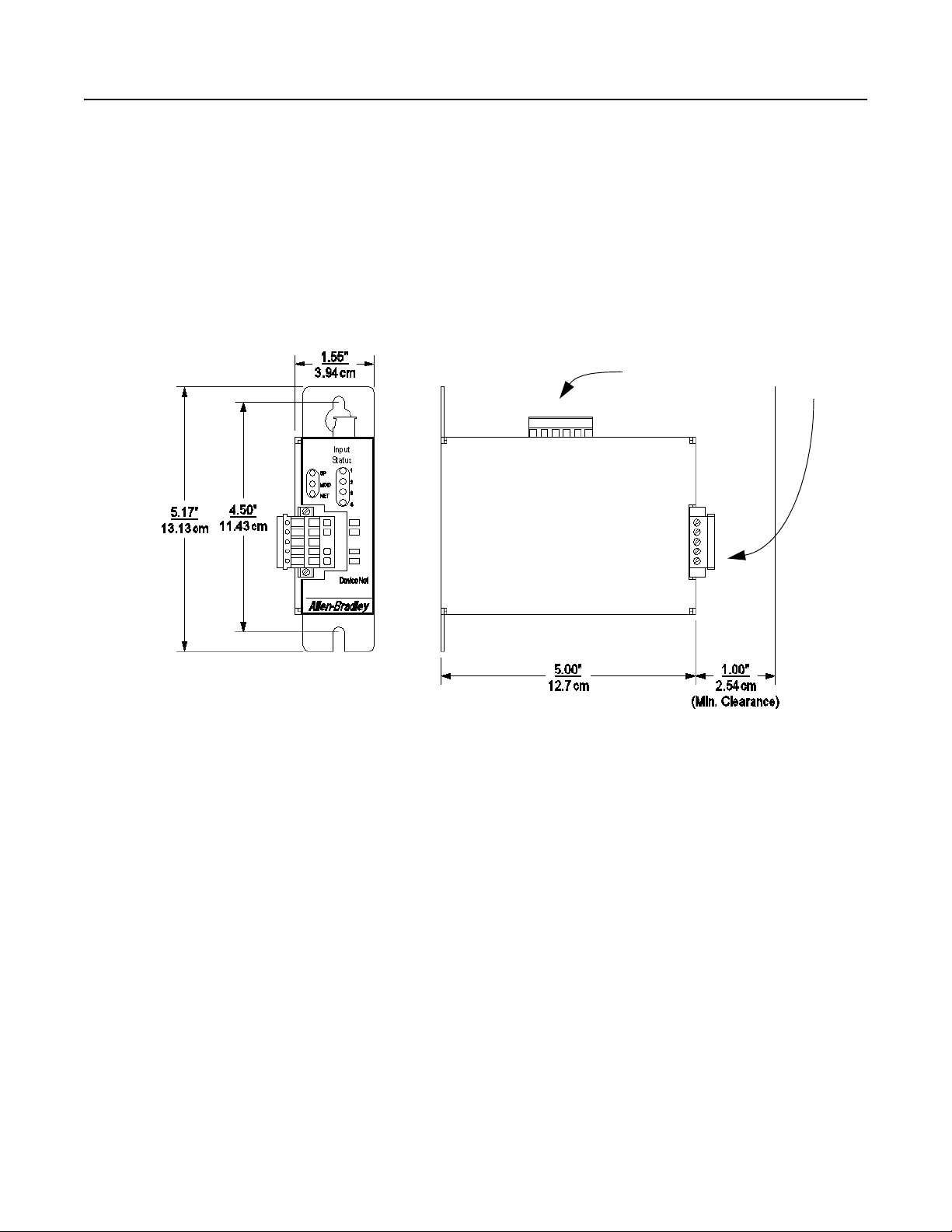
When choosing a suitable mounting location, allo w 1.0” (2.54cm)
clearance from the front of the module to the door of the enclosure or other devices. This clearance is needed for DeviceNet wiring harness/bend radius.
enclosure.
Publication 2100-UM001B-EN-P – January 2001
Page 26
2-6 Installation
Mount the module to the panel with #10 hardware as detailed in
Figure 2.2.
Figure 2.2
Mounting Dimensions
Digital Input
Connector
DeviceNet
Connector
Publication 2100-UM001B-EN-P – January 2001
Page 27
Installation 2-7
3. Remove power from the network.
4. Insert the DeviceNet cable wires into the 10-pin connector . Mak e
sure you follow the color key next to the connector receptacle on
the module.
ATTENTION: If you wire the 10-pin header after
you’ve connected it to the module, static control
!
precautions are required. Device malfunction may occur
if you do not follow ESD control procedures. If yo u are
not familiar with static control procedures, refer to
Allen-Bradley Publication 8000-4.5.2, Guarding
Against Electrostatic Damag e, or other applicable ESD
protection handbook.
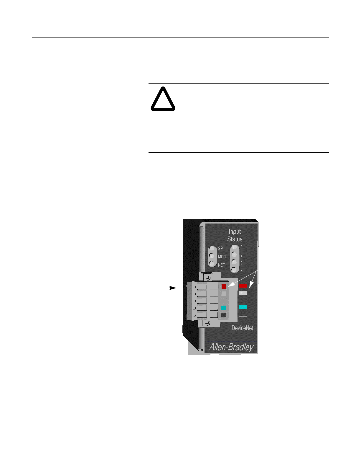
Figure 2.3
DeviceNet Connections
10-pin Dual Row
DeviceNet Connection
Color Key
1 - Red - V+
2 - White-CAN_H
3 - Shield
4 - Blue-CAN_L
5 - Black- V-
Front View of 2100-GK61 Module
Publication 2100-UM001B-EN-P – January 2001
Page 28
2-8 Installation
5. Plug the connector into the module.
A TTENTION: Danger of electrical shock exists if
power is not disconnected to Digital Input Devices.
!
Verify power is removed before proceeding.
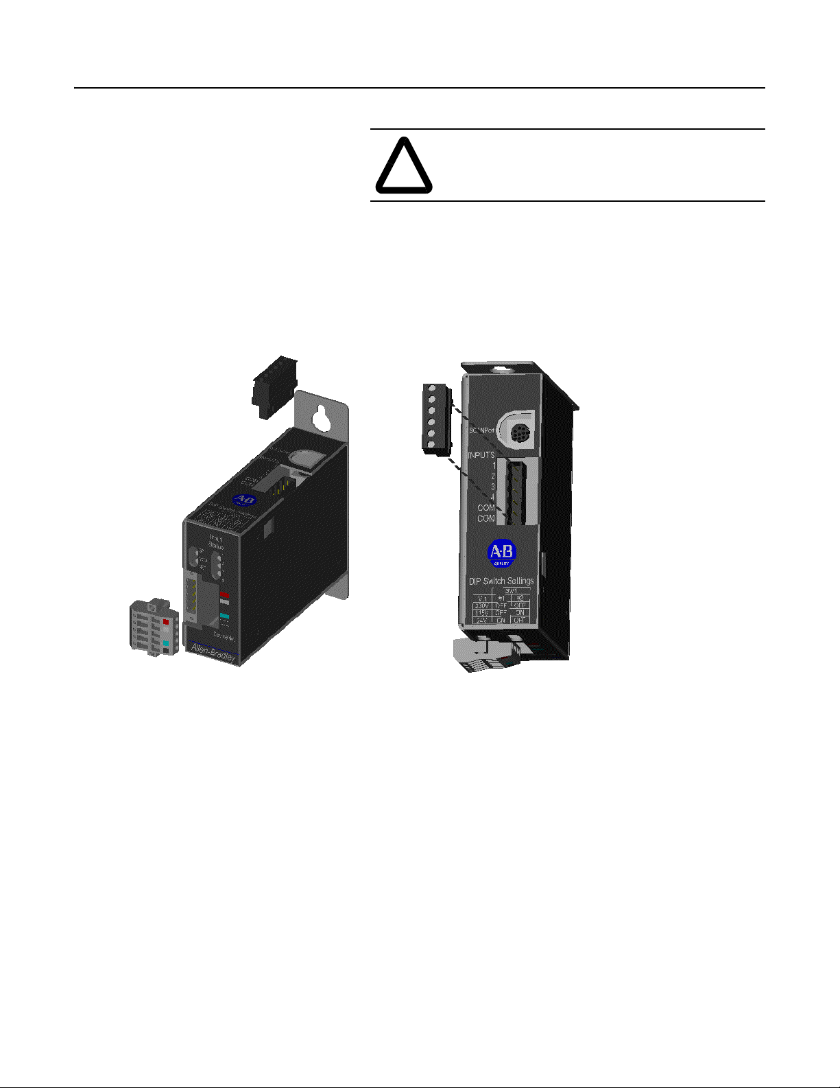
6. Connect the Digital Inputs to the Digital Input six (6) pin connec-
tors. Below is the connection pinout detail.
Figure 2.4
Digital Input Connections
Pin 1 = Input #1
Pin 2 = Input #2
Pin 3 = Input #3
Pin 4 = Input #4
Pin 5 = Input Common
Pin 6 = Input Common
Publication 2100-UM001B-EN-P – January 2001
7. Plug the Input connector into the module.
8. Connect the SCANport cable to the communications adapter and
then to the SCANport product.
Page 29
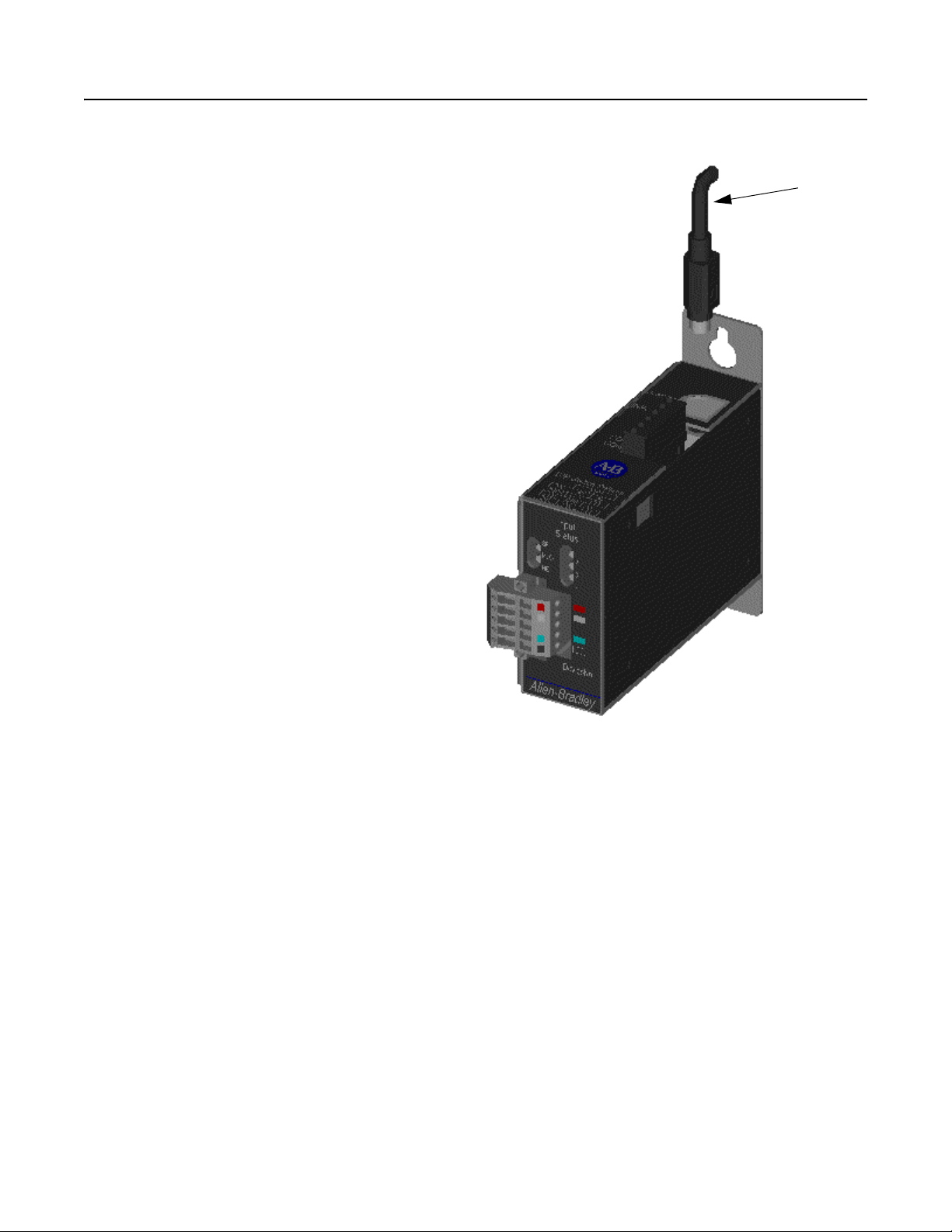
Figure 2.5
SCANport Connection
Installation 2-9
SCANport Cable
9. Reapply power to the DeviceNet network.
10. If necessary, apply power to the connected SCANpo rt product
and to the Digital Inputs.
Publication 2100-UM001B-EN-P – January 2001
Page 30

2-10 Installation
Your 2100-GK61 module is now installed. The SCANport LED is
green. The network and module LEDs are blinking green. If your
module’s LEDs are different, refer to Chapter 7, Troubleshooting, for
more information.
You must now edit the adapter’s node address, and you may want to
edit some of its other parameters. Refer to Chapter 3 for more
information.
Removing the DeviceNet to SCANport
Communication Module with Digital Inputs
(2100-GK61)
T o remo ve the De viceNet to SCANport Communication Module with
Digital Inputs, you need to:
1. Disconnect Input Power from Digital Inputs.
ATTENTION: Electrical shock hazard exists if
power is not disconnected to Digital Input Devices.
!
Verify power is removed before proceeding.
2. Remove the SCANport cable from the SCANport product and
then from the module.
3. Unplug the 10-pin DeviceNet connector from the module.
4. Unplug the 6-pin Digital Input connector from the module.
5. Remove the module from the panel.
Publication 2100-UM001B-EN-P – January 2001
Page 31

Chapter 3
Configuring the DeviceNet to
SCANport Communication Module
with Digital Inputs
Using RSNetWorx for DeviceNet
Chapter Objectives Chapter 3 provides information that you need to configure the
2100-GK61 module over the DeviceNet network. In this chapter, you
will read about the following:
• Factory-default settings for the module.
• RSNetWorx software.
• Equipment necessary to use RSNetWorx software.
• Editing the 2100-GK61 adapter’s parameters using RSNetWorx
software.
Factory Default Settings for the
2100-GK61
This section assumes you have experience using RSNetWorx
software to configure a DeviceNet network.
The factory-default settings of the DeviceNet to SCANport
Communication Module with Digital Inputs include the following:
• 16-bit Logic Command/Status enabled for polling.
• 16-bit Reference/Feedback enabled for polling.
• If the scanner is put into program mode or the network faults, the
SCANport product will be faulted by the module. (Firmware
must be version 2.080 or above. Earlier firmware versions are
flash upgradeable. Consult the factory.)
• A node address of 63.
• DeviceNet autobaud detection enabled.
Publication 2100-UM001B-EN-P – January 2001
Page 32

3-2 Configuring the DeviceNet to SCANport Communication Module with Digital Inputs
You should change the node address by editing the DN Node Address
(2) parameter. Note: The number in ( ) following the parameter name
corresponds to the parameter number as found in Appendix B,
DeviceNet to SCANport Communication Module with Digital Inputs
Parameters. You must change the autobaud detection if no other
devices on your DeviceNet network have a fixed data rate by editing
DN Data Rate (3) parameter in the module.
Important: Refer to Appendix B, DeviceNet to SCANport
Communication Module with Digital Inputs Parameters, for
information on changing the node address or data rate.
If you wish to change other functions (e. g., Fault Con figurable in puts)
or add more functions (e.g., datalinks), you must edit the adapter’s
parameters. To do so, refer to:
• Appendix B, DeviceNet to SCANport Communication Module
with Digital Inputs P arameter s, for detailed information about the
adapter’s parameters.
• Instructions in this chapter on using RSNetW orx for De viceNet to
edit parameters.
What is RSNetWorx for
DeviceNet?
Required Equipment and
Software
RSNetWorx for DeviceNet is a Windows application that lets you
configure DeviceNet networks. Using a graphical representation of
your network, you can configure network-wide parameters and the
network-wide schedule.
After installing or mounting the adapter, you can use RSNetWorx for
DeviceNet to configure or edit the adapter’s parameters.
Before configuring or editing your adapter’s parameters, your PC
must be:
• Running RSNetWorx for DeviceNet. Refer to
http://www.software.rockwell.com for more information on this
product.
• Connected to and communicating with the DeviceNet netw o rk
using a 1784-PCD card, a 1784-PCID card, a 1784-PCID5 card,
or a 1770-KFD adapter running with RSLinx. Refer to
http://www.software.rockwell.com for more information on the
RSLinx product. Refer to http://www.ab.com/products.html for
more information on “DeviceNet Network, ” under “Networks and
Communication Products.”
Publication 2100-UM001B-EN-P – January 2001
Page 33

Configuring the DeviceNet to SCANport Communication Module with Digital Inputs 3-3
Using RSNetWorx to Edit Your
Adapter’s Parameters
The following instructions describe how to use RSNetWorx for
DeviceNet in online mode to edit your adapter’s parameters.
1. Use RSLinx to configure the DeviceNet drivers for your system
using the Configure Drivers option in the Communications
menu.
2. Start RSNetWorx for DeviceNet. The RSNetWorx for DeviceNet
screen appears as seen in Figure 3.1.
Figure 3.1
RSNetWorx for DeviceNet Screen
3. In the Network menu, select Online, or click on the Online icon
as indicated in Figure 3.2.
4. The Browse Network screen appears asking to select which
network you wish to go online with. Select the DeviceNet
network desired and click on OK.
Publication 2100-UM001B-EN-P – January 2001
Page 34

3-4 Configuring the DeviceNet to SCANport Communication Module with Digital Inputs
Figure 3.2
Online Screen
Step #3
Step #4
5. The network will be scanned and the screen will build the online
configuration as shown in Figure 3.3.
Figure 3.3
RSNetWorx Graphical View
Publication 2100-UM001B-EN-P – January 2001
In Figure 3.3, Node 00 is scanner, Node 62 is the PC, and Node 63 is
the module we are configuring.
Your module appears as Node 63 by default. If you have changed its
node address parameter and reset the module, its new node address
will appear on the screen.
Page 35

Configuring the DeviceNet to SCANport Communication Module with Digital Inputs 3-5
Important: If the module does not appear:
– Verify there is an EDS file for the device. Refer to “Creating
an EDS file for your SCANport Product” in Chapter 4,
Configuring a Scanner to Communicate with the
Adapter.
– Verify that the device has a unique node address. Check the
network LED on the module. If it is red, it is not an unique
address. You must configure the module in a point-to-point
connection.
6. Double-click the icon for the 2100-GK61 module. (In our
example, it is node 63 in Figure 3.3.)
The DeviceNet Configuration screen appears for the selected device.
The screen has three tabs to choose from: General, Device
Parameters, and EDS I/O Default.
The General tab allows you to give the device a name and add a
description for the device. These names and descriptions will be used
to represent and describe the product throughout RSNetWorx for
DeviceNet.
Step #7
The DeviceNet Parameters and EDS I/O Default tabs allow you to
see the parameters and configuration of the device selected.
7. Click on the Device Parameters tab . A dialog box req uesting to
upload or download the de vice’s parameters appears. Click on the
Upload button to upload the parameters from the module. The
screen listing all the device’s parameters appears. In this example
the 2100-GK61 is configured with an SMP3 device.
Figure 3.4
Device Parameters, all
Publication 2100-UM001B-EN-P – January 2001
Page 36

3-6 Configuring the DeviceNet to SCANport Communication Module with Digital Inputs
8. Click on the Groups pull-down arrow and select DeviceNet
Module. The display changes, listing only the parameters
associated with the 2100-GK61.
Figure 3.5
Device Parameters, Module Only
Step #8
Step #9
Step #11
Step #10
9. Double click on the parameter(s) you wish to edit. Change the
data to the desired value (refer to Appendix B for acceptable
values for each parameter). A lock icon indicates that the
parameter is read-only and cannot be changed.
10. Click on the Download to Device button to save the changes
made to the module.
Important: It may be necessary to reset the adapter for the changes
to take effect. Refer to Appendix B to see if the parameter you
changed required the module to be reset in order to take effect.
11. Click on the OK button to return to the graph screen.
Publication 2100-UM001B-EN-P – January 2001
Page 37

Chapter 4
Configuring a Scanner to
Communicate with the Adapter
Chapter Objectives Chapter 4 provides instructions for configuring your scanner to
communicate with the 2100-GK61 module. This allows the product
connected to the adapter to be an active node on the DeviceNet
network. In this chapter, you will read about the following:
• RSNetWorx for DeviceNet software.
• Equipment and software needed for the configuration.
• Configuring a PLC, SLC, or ControlLogix scann er to
communicate with the adapter.
This chapter assumes you have experience using RSNetWorx for
DeviceNet to configure a DeviceNet network.
What is RSNetWorx for
DeviceNet?
Required Equipment and
Software
RSNetWorx for DeviceNet is a Windows application that lets you
configure DeviceNet networks. Using a graphical representation of
your network, you can configure network-wide parameters and the
network-wide schedule.
After installing and configuring the DeviceNet to SCANport
Communication Module with Digital Inputs, you can use RSNetW orx
for DeviceNet to configure the scanner to recognize and communicate
with it.
For more information on RSNetWorx for DeviceNet, refer to the
RSNetWorx for DeviceNet online help.
Before configuring the scanner, your PC must be:
• Running RSNetWorx for DeviceNet. Refer to
http://www.software.rockwell.com for more information on this
product.
• Connected to and communicating with the DeviceNet network
using a 1784-PCD card, a 1784-PCID card, a 1784-PCID5 card,
or a 1770-KFD adapter running with RSLinx. Refer to
http://www.software.rockwell.com for more information on the
RSLinx product. Refer to http://www.ab.com/products.html for
more information on “DeviceNet Network” under “Networks an d
Communication Products.”
Publication 2100-UM001B-EN-P – January 2001
Page 38

4-2 Configuring a Scanner to Communicate with the Adapter
Getting Started For the scanner on the DeviceNet network to transmit control I/O
and/or messages to the adapter, you must first configure it to
recognize and communicate with the adapter.
The following instructions describe how to use RSNetWorx for
DeviceNet to configure a new DeviceNet network in online mode.
The main steps in the configuration are:
• Using online mode in RSNetWorx for DeviceNet.
• Downloading an EDS file for your SCANport product (if
necessary).
• Configuring the PLC scanner or SLC scanner.
Using Online Mode in
RSNetWorx for DeviceNet
Although you can configure the DeviceNet network offline, it is
easier to configure the network online because you can see a
graphical representation of your network in RSNetWorx for
DeviceNet. The following directions explain how to use online mode.
1. Start RSLinx to configure the DeviceNet Drivers for your
system, using the Configure Drivers option in the
Communications menu.
2. Start RSNetWorx for DeviceNet. The RSNetW orx for DeviceNet
screen appears.
Figure 4.1
RSNetWorx for DeviceNet Screen
Publication 2100-UM001B-EN-P – January 2001
Page 39

Configuring a Scanner to Communicate with the Adapter 4-3
3. In the Network menu, select Online, or click on the Online icon
as indicated in Figure 4.2.
4. The Browse Netw ork screen appears, requesting specif ication of
which network you wish to go online with. Select the DeviceNet
network desired and click on OK.
Figure 4.2
Online Screen
Step # 3
Step # 4
5. The network will be scanned and the screen will build the online
configuration as shown in Figure 4.3.
Figure 4.3
Online Graphical View
Important: In our example, our module is Node 3. It has a
Unrecognized Device icon, and the error code lists it as an
unregistered device, so we will need to download an EDS file for it.
Publication 2100-UM001B-EN-P – January 2001
Page 40

4-4 Configuring a Scanner to Communicate with the Adapter
You are now in online mode. You must check to see if you need an
EDS file for the device you are adding. Refer to the “Download an
EDS file for Your SCANport product” selection in this chapter.
Downloading an EDS File for
Your SCANport Product
Each DeviceNet product has a unique EDS file based on electrical
ratings, I/O, and DeviceNet-to-SCANPort communication interface
(if used). For IntelliCENTER software or RSNetWorx to function
properly, a matching EDS file must be registered on the PC or laptop
connected to DeviceNet network.
• An Electronic Data Sheet (EDS) is a simple file format that
includes the device’s configurable parameters.
• There is a unique EDS file for each size of E3, each type of DSA,
and every combination of GK61 and connected ScanPort Product
(Drive, SMC, SMP-3).
• EDS files can be used by network tools (such as RSNetworx for
DeviceNet) to read or set device parameters.
• Each vendor is required to supply the configuration information.
The vendor must also supply an EDS file to successfully pass
conformance testing.
1. To get information about an unregistered Device in RSNetworx
for DeviceNet, double-click the icon.
Figure 4.4
Unrecognized Device in RSNetWorx
Publication 2100-UM001B-EN-P – January 2001
Step #1
Page 41

Configuring a Scanner to Communicate with the Adapter 4-5
2. An Unrecognized Device screen appears. The device identity can
be obtained from this screen. Included in the example shown in
Figure 4.4 are Vendor Code (1), Device Code (122), Product
Code (20), and Major Revision Code (1).
RSNetWorx Information Screen for Unrecognized Device
Step #2
3. EDS files are available for download at the Allen-Bradley web
site http://www.ab.com/networks/eds. There is a unique EDS
(Electronic Data Sheet) file for each size of E3, each type of
DSA, and every combination of 2100-GK61 and connected
SCANPort Product (Drive, SMC, or SMP-3).
Publication 2100-UM001B-EN-P – January 2001
Page 42

4-6 Configuring a Scanner to Communicate with the Adapter
4. In the example below, a search is being performed for an EDS file
for a 1336 drive with 2100-GK61. The procedure involves (1)
selecting Smart MCC for the device type 2100-GK61, (2)
entering at least a portion of the catalog numbers, and (3) clicking
on Search.
Figure 4.5
EDS Search for 1336 Drive with 2100-GK61
Step #4
5. The next example displays an EDS search for an SMP-3 SolidState Overload Relay with 2100-GK61. The procedure involves
(1) selecting Smart MCC for the device type 2100-GK61, (2)
entering SMP-3 for the product name, and (3) clicking on
Search.
Figure 4.6
EDS Search for SMP-3 with 2100-GK61
Step #5
Publication 2100-UM001B-EN-P – January 2001
Page 43

Configuring a Scanner to Communicate with the Adapter 4-7
6. The search results display nine different EDS files available for a
combination of an SMP-3 with a 2100-GK61. The correct one
can be selected based on SMP-3 current range.
Figure 4.7
EDS Search Results for SMP-3 with 2100-GK61
7. By clicking on Rockwell Automation/Allen-Bradley next to the
chosen product description in Figure 4.8, an EDS File Details
screen appears (Figure 4.9). The example for a “1336 Drive”
provides file detail and a file download button. After clicking on
the Download File button, do wnload the EDS f ile to a temporary
directory on your PC’s hard drive.
Figure 4.8
EDS File Details and Download Button
Publication 2100-UM001B-EN-P – January 2001
Page 44

4-8 Configuring a Scanner to Communicate with the Adapter
8. To register the EDS file, start EDS Wizard from the toolbar in
RSNetWorx for DeviceNet.
Figure 4.9.
EDS Wizard in RSNetWorx for DeviceNet
Step #8
9. Select Register an EDS file(s).
Figure 4.10
Registering an EDS File
Step #9
Publication 2100-UM001B-EN-P – January 2001
Page 45

Configuring a Scanner to Communicate with the Adapter 4-9
10. A single EDS file or a directory of EDS f iles may be registered as
illustrated here. After selecting file or directory, click Next to
continue.
Figure 4.11
Registering an EDS File
Step #10
11. EDS files are evaluated for errors. Click Next to continue.
Figure 4.12
EDS File Validity Test
Step #11
Publication 2100-UM001B-EN-P – January 2001
Page 46

4-10 Configuring a Scanner to Communicate with the Adapter
12. The Change Icon screen now appears. Here you will be able to
select an icon that best represents the connected devices for the
graph presentation of the network.
13. Select the device description yo u wish to change. In this e xample,
we click on the test “SMP-3 via 2100-GK61.” Click the Change
icon button.
Figure 4.13
Change Icon Screen
Step #13
Publication 2100-UM001B-EN-P – January 2001
Page 47

Configuring a Scanner to Communicate with the Adapter 4-11
14. Pictures of various icons appear. Select the icon by clicking on
the one which best represents your device.
Figure 4.14
Icon Options
15. Click Next to complete EDS file registration.
Figure 4.15
Final Task Summary Screen
Step #15
Publication 2100-UM001B-EN-P – January 2001
Page 48

4-12 Configuring a Scanner to Communicate with the Adapter
16. Click Finish.
Figure 4.16
EDS Installation Complete Screen
Step #16
17. The program updates the EDS directory registry for the computer
and redraws the graphical representation of the device with the
new icon as shown.
Figure 4.17
Updated Online Screen
Step #17
Publication 2100-UM001B-EN-P – January 2001
Page 49

Configuring a Scanner to Communicate with the Adapter 4-13
18. Registered EDS files are stored on a PC’s hard drive under
c:\Program Files\Rockwell Software\RS Common\Eds. A typical
location is shown here.
Figure 4.18
PC Hard Drive Directory Example
tep 18
Additional EDS detail can be viewed by opening the file with a text
editor such as WordPad. EDS identifiers are in decimal within the
body of the EDS document. RSNetWorx for DeviceNet also uses
decimal IDs (1 122 1026 4). (Refer to the example in Figure 4.20.)
The equivalent EDS file name is in hexadecimal
(0001007A04020400.eds).
Figure 4.19
EDS File Detail
Publication 2100-UM001B-EN-P – January 2001
Page 50

4-14 Configuring a Scanner to Communicate with the Adapter
A scientific calculator, such as the one in Windows, can be used to
convert decimal to hexadecimal and v.s. In the example, 122 is
entered in the calculator with Dec button selected. When the Hex
button is chosen, the display changes to 7A.
1 122 1026 4 ID code in decimal = 0001 007A 0402 0400 in
hexadecimal.
Figure 4.20
Windows Scientific Calculator Used for Conversion
Figure 4.21
Device Configuration Screen
Step #19
Important: This screen allows you to edit any of the parameters in
the SMP or adapter itself. Refer to Chapter 3, Configuring the
DeviceNet to SCANport Communication Module with Digital Inputs,
for information on editing parameters.
Publication 2100-UM001B-EN-P – January 2001
19. Click on the Cancel button. The online screen appears.
Once all your devices have registered EDS files for RSNetWorx to
Page 51

Configuring a Scanner to Communicate with the Adapter 4-15
use, do one of the following.
Configuring a Scanner
To configure the scanner, you verify its properties, add d e vi ces on the
network to its scan list, and determine how the scanner will
communicate (e.g., polling) with each device. Follow these
directions:
If Using: Refer To:
PLC Scanner (1771-SDN) Configuring a PLC Scanner (1771-SDN) to
Communicate with the Adapter on page 4-15
SLC Scanner (1747-SDN) Configuring an SLC Scanner (1747-SDN) to
Communicate with the Adapter on page 4-23
ControlLogix Scanner (1756DNB)
RSNetworx for DeviceNet to
edit parameters.
Configuring a PLC Scanner
(1771-SDN) to Communicate
with the Adapter
Configuring a ControlLogix Scanner (1756-DNB) to
Communicate with the Adapter on page 4-30
Chapter 3, Configuring the DeviceNet to SCANport
Communication Module with Digital Inputs
The following instructions describe how to configure a PLC scanner
on a DeviceNet network.
For the PLC to recognize your device, you must do the following:
• Configure the PLC scanner.
• Map your adapter to the PLC scanner (1771-SDN).
1. In the Online screen, double-click on the scanner icon. The
1771-SDN Scanner Module properties and configuration screen
appears.
Publication 2100-UM001B-EN-P – January 2001
Page 52

4-16 Configuring a Scanner to Communicate with the Adapter
Figure 4.22
1771-SDN Configuration Dialog Box
Publication 2100-UM001B-EN-P – January 2001
Page 53

Configuring a Scanner to Communicate with the Adapter 4-17
The dialog box contains 6 data tabs which are used to configure
various portions of the scanner. The General tab allows the user to
edit the name and descriptions of the scanner . The Module tab allo ws
the user to configure the scanner setup properties. The Scanlist tab
allows the user to choose which components the scanner will scan for
data. The Input and Output tab is where the user sets up where the
data from the scanned devices is kept to be used by the PLC
processor. Finally, the Summary tab allows the user to view a concise
summary of how the scanner has been configured.
2. On the General page, place the cursor in the name field and type
the name you want to assign the scanner. If you want to add a
description to the scanner, place the cursor in the description f ield
and enter a description. Click on the Apply button to save the
information.
3. Click on the Module tab. A dialog box will appear requesting to
upload or download information from the scanner. Click on
Upload. All the scanlist information currently stored in the
scanner will be uploaded. Once the upload is complete, the
Module screen will appear.
Figure 4.23
1771 SDN Module Screen
Step #4
Verify the default values listed on this page. Edit them as necessary.
Refer to RSNetworx for DeviceNet online help for more information.
4. Click Apply to save.
Publication 2100-UM001B-EN-P – January 2001
Page 54

4-18 Configuring a Scanner to Communicate with the Adapter
5. Click on the Scanlist tab so that the Scanlist page appears.
Figure 4.24
Scanlist Screen
6. Select the available devices you wish to add to the scan list.
Verify that the Automap on Add box is checked. This will map
the devices into the scanner’ s memory automatically when added.
Refer to the RSNetWorx for DeviceNet help menu for additional
information on automapping. Once a device is selected, click on
the Add (>) or Add All (>>) button.
Step #6
Figure 4.25
Scanlist Configuration Screen
Step #6
Step #7
Publication 2100-UM001B-EN-P – January 2001
Page 55

Configuring a Scanner to Communicate with the Adapter 4-19
7. Modify each device’s I/O parameters if needed. Select the device
and click on the Edit I/O Parameters button. The I/O Parameters
dialog screen appears.
Figure 4.26
I/O Configuration Edit Screen
Publication 2100-UM001B-EN-P – January 2001
Page 56

4-20 Configuring a Scanner to Communicate with the Adapter
8. Make the changes as necessary. You must configure your PLC
based on how your adapter’s parameters are configured and how
you want your module to send and receiv e data from the netw ork.
Refer to the following table:
If Using: Refer To:
Polled Polled Allocation on page B-5.
COS (Change of State) COS (Change of State) Allocation on page B-7.
Cyclic Cyclic Allocation on page B-8.
Polled and COS Polled and COS Allocation on page B-10.
Polled and Cyclic Polled and Cyclic Allocation on page B-11.
9. Click OK to return to the Scanlist screen.
10. Click on the Apply button. A dialog box appears asking if you
wish to download the changes to the device. Click on Yes.
Important: If the processor is not in Program mode, a dialog box
will appear stating which mode the processor is in. Clicking on the
OK button returns the Scanlist screen without
information to the processor. You must now place the processor in
program mode and repeat the apply function.
downloading any
11. Click on the Input tab to view the input table map. From this
screen you can customize the arrangement of the scanner’s data
table. Refer to the RSNetWorx online help for additional
information.
Figure 4.27
Input Data Table Map Screen
Publication 2100-UM001B-EN-P – January 2001
Page 57

Configuring a Scanner to Communicate with the Adapter 4-21
12. Click on the Output tab to view the output table map. From this
screen you can customize the arrangement of the scanner’s data
table. Refer to the RSNetWorx online help for additional
information.
Figure 4.28
Output Data Table Map Screen
Publication 2100-UM001B-EN-P – January 2001
Page 58

4-22 Configuring a Scanner to Communicate with the Adapter
13. Click on the Summary tab. This screen provides the user with a
concise summary of how the scanner has been configured. Note:
all of the information that appears on this page is read-only . If you
want to change any of the parameters, you have to edit them on
the appropriate property page.
Figure 4.29
Summary Screen
14. Click on the OK button. You are returned to the online screen.
15. To save the information just entered to your computer, select
Save As under the File menu.
16. Select a path to store the information.
17. Enter a file name and click on Save.
Figure 4.30
“Save As” Dialog Screen
Step #17
Publication 2100-UM001B-EN-P – January 2001
Page 59

Configuring a Scanner to Communicate with the Adapter 4-23
Your device is now configured on the DeviceNet network. The
network LED on the module is solid green. If it is not, refer to
Chapter 7, Troubleshooting, for more information.
Refer to Chapter 5, Ladder Logic Programming—Including Reading
Inputs, for information on creating a PLC Ladder Logic Program.
Configuring an SLC Scanner
(1747-SDN) to Communicate
with the Adapter
The following instructions describe how to conf igure an SLC scanner
on a DeviceNet network.
For the SLC to recognize your device, you must do the following:
• Configure the SLC Scanner.
• Map your adapter to the SLC (1747-SDN).
Configuring an SLC Scanner
To configure the scanner, you verify its properties, add d e vi ces on the
network to its scan list, and determine how the scanner will
communicate (e.g., polling) with each device. Follow these
directions:
1. In the Online screen, double-click on the scanner icon. The
1747-SDN Scanner Module properties and configuration screen
appears.
Figure 4.31
1747-SDN Configuration Dialog Box
The dialog box contains six data tabs which are used to configure
various portions of the scanner. The General tab allows the user to
edit the name and descriptions of the scanner . The Module tab allo ws
the user to configure the scanner setup properties. The Scanlist tab
Publication 2100-UM001B-EN-P – January 2001
Page 60

4-24 Configuring a Scanner to Communicate with the Adapter
allows the user to choose which components the scanner will scan for
data. The Input and Output tabs are for setting up where the data
from the scanned devices is kept for use by the SLC processor.
Finally , the Summary tab allows the user to view a concise summary
of how the scanner has been configured.
2. On the General page, place the cursor in the name field and type
the name you want to assign the scanner. If you want to add a
description to the scanner, place the cursor in the d escription field
and enter a description. Click on the Apply button to save the
information.
3. Click on the Module tab. A dialog box will appear requesting to
upload or download information from the scanner. Click on
Upload. The scanlist information currently stored in the scanner
will be uploaded. Once the upload is complete, the Module
screen will appear.
Figure 4.32
1747-SDN Module Configuration Screen
Step #4
Verify the default values listed on this page. Edit them as necessary.
Refer to RSNetWorx for DeviceNet online help for more information.
4. Click Apply to save.
5. Click on the Scanlist tab so that the Scanlist page appears.
Publication 2100-UM001B-EN-P – January 2001
Page 61

Configuring a Scanner to Communicate with the Adapter 4-25
Figure 4.33
1747-SDN Scanlist Configuration Screen
Step #6
6. Select the available de vices you wish to add to the Scanlist. Verify
that the Automap on Add box is checked. This will map the
devices into the scanner’s memory automatically when added.
Refer to the RSNetWorx for DeviceNet help menu for additional
information on automapping. Once a device is selected, click on
the Add (>) or Add All (>>) button.
Figure 4.34
Scanlist Configuration Screen
Step #7
Publication 2100-UM001B-EN-P – January 2001
Page 62

4-26 Configuring a Scanner to Communicate with the Adapter
7. Modify each device’s I/O parameters if needed. Select the device
and click on the Edit I/O Parameters button. The I/O Parameters
dialog screen appears.
Figure 4.35
I/O Configuration Edit Screen
8. Make the changes as necessary. You must configure your PLC
based on how your adapter’s parameters are configured and how
you want your module to send and receiv e data from the netw ork.
Refer to the following table.
If Using: Refer To:
Polled Polled Allocation on page B-5.
COS (Change of State) COS (Change of State) Allocation on page B-7.
Cyclic Cyclic Allocation on page B-8.
Polled and COS Polled and COS Allocation on page B-10.
Polled and Cyclic Polled and Cyclic Allocation on page B-11.
9. Click OK to return to the Scanlist screen.
10. Click on the Apply button. A dialog box appears asking if you
wish to download the changes to the device. Click on Yes.
Important: If the processor is not in Program mode, a dialog box
will appear stating which mode the processor is in. Clicking on the
OK button returns you to the Scanlist screen without
downloading
any information to the processor. You must now place the process in
program mode and repeat the apply function.
Publication 2100-UM001B-EN-P – January 2001
Page 63

Configuring a Scanner to Communicate with the Adapter 4-27
11. Click on the Input tab to view the input table map. From this
screen you can customize the arrangement of the scanner’s data
table. Refer to the RSNetWorx online help for additional
information.
Figure 4.36
Input Data Table Mapping Screen
Publication 2100-UM001B-EN-P – January 2001
Page 64

4-28 Configuring a Scanner to Communicate with the Adapter
12. Clicking on the Advanced button moves to the advance memory
mapping screen. From this screen you can specify where to map
the data to.
13. Selecting the Memory Arrow under the Map To: allows you to
select Discrete or M File Memory. This example leaves the
mapping in discrete memory.
Figure 4.37
Advanced Mapping Screen
Step #13
14. Click on the Output tab to view the output table map. From this
screen you can customize the arrangement of the scanner’s data
table. Refer to the RSNetWorx online help for additional
information.
Figure 4.38
Output Data Table Mapping Screen
Publication 2100-UM001B-EN-P – January 2001
Page 65

Configuring a Scanner to Communicate with the Adapter 4-29
15. Click on the Summary tab. This sc reen provides the user with a
concise summary of how the scanner has been configured. Note:
all of the information that appears on this page is read only . If you
want to change any of the parameters, you have to edit them on
the appropriate property page.
Figure 4.39
Summary Screen
16. Click on the OK button. You are returned to the online screen.
17. To save the information just entered, select Sav e As under the
File menu.
18. Select a path to store the information.
19. Enter a file name and click on Save.
Publication 2100-UM001B-EN-P – January 2001
Page 66

4-30 Configuring a Scanner to Communicate with the Adapter
Figure 4.40
“Save As” Dialog Screen
Step #19
Step #19
Configuring a ControlLogix
Scanner (1756-DNB) to
Communicate with the Adapter
Your device is now configured on the DeviceNet network. The
network LED on the module is solid green. If it is not, refer to
Chapter 7, Troubleshooting, for more information.
Refer to Chapter 5, Ladder Logic Programming—Including Reading
Inputs, for information on creating a Ladder Logic Program.
The following instructions describe how to configure a ControlLogix
scanner on a DeviceNet network.
For the ControlLogix to recognize your device, you must do the
following:
• Configure the ControlLogix scanner.
• Map your adapter to the ControlLogix scanner (1756-DBN).
To configure the scanner, you verify its properties, add d e vi ces on the
network to its scan list, and determine how the scanner will
communicate (e.g., polling) with each device. Follow these
directions:
1. In the Online screen, double-click on the scanner icon. The
1756-DBN Scanner Module properties and configuration screen
appears.
Publication 2100-UM001B-EN-P – January 2001
Page 67

Configuring a Scanner to Communicate with the Adapter 4-31
Figure 4.41
1756-DBN Configuration Dialog Box
Publication 2100-UM001B-EN-P – January 2001
Page 68

4-32 Configuring a Scanner to Communicate with the Adapter
The dialog box contains six data tabs which are used to configure
various portions of the scanner. The General tab allows the user to
edit the name and descriptions of the scanner . The Module tab allows
the user to configure the scanner setup properties. The Scanlist tab
allows the user to choose which components the scanner will scan for
data. The Input and Output tab is where the user sets up where the
data from the scanned devices is kept for use by the PLC processor.
Finally , the Summary tab allows the user to view a concise summary
of how the scanner has been configured.
2. On the General page, place the cursor in the name field and type
the name you want to assign the scanner. If you want to add a
description to the scanner, place the cursor in the d escription field
and enter a description. Click on the Apply button to save the
information.
3. Click on the Module tab. A dialog box will appear requesting to
upload or download information from the scanner. Click on
Upload. All the scanlist information currently stored in the
scanner will be uploaded. Once the upload is complete, the
Module screen will appear.
Figure 4.42
1756-DBN Module Screen
Verify the default values listed on this page. Edit them as necessary.
Refer to RSNetworx for DeviceNet online help for more information.
Publication 2100-UM001B-EN-P – January 2001
4. Click Apply to save.
Page 69

Configuring a Scanner to Communicate with the Adapter 4-33
5. Click on the Scanlist tab so that the Scanlist page appears.
Figure 4.43
Scanlist Screen
6. Select the available de vices you wish to add to the scanlist. Verify
that the Automap on Add box is checked. This will map the
devices into the scanner’s memory automatically when added.
Refer to the RSNetWorx for DeviceNet help menu for additional
information on automapping. Once a device is selected, click on
the Add (>) or Add All (>>) button.
Figure 4.44
Scanlist Configuration Screen
Publication 2100-UM001B-EN-P – January 2001
Page 70

4-34 Configuring a Scanner to Communicate with the Adapter
7. Modify each device’s I/O parameters if needed. Select the device
and click on the Edit I/O Parameters button. The I/O Parameters
dialog screen appears.
Figure 4.45
I/O Configuration Edit Screen
Publication 2100-UM001B-EN-P – January 2001
Page 71

Configuring a Scanner to Communicate with the Adapter 4-35
8. Make the changes as necessary. You must configure your PLC
based on how your adapter’s parameters are configured and how
you want your module to send and receiv e data from the netw ork.
Refer to the following table:
If Using: Refer To:
Polled Polled Allocation on page B-5.
COS (Change of State) COS (Change of State) Allocation on page B-7.
Cyclic Cyclic Allocation on page B-8.
Polled and COS Polled and COS Allocation on page B-10.
Polled and Cyclic Polled and Cyclic Allocation on page B-11.
9. Click on OK to return to the Scanlist screen.
10. Click on the Apply button. A dialog box appears asking if you
wish to download the changes to the device. Click on Yes.
Important: If the processor is not in Program mode, a dialog box
will appear stating which mode the processor is in. Clicking on the
OK button returns the Scanlist screen without
downloading any
information to the processor. You must now place the processor in
program mode and repeat the apply function.
11. Click on the Input tab to view the input table map. From this
screen you can customize the arrangement of the scanner’s data
table. Refer to the RSNetWorx online help for additional
information.
Figure 4.46
Input Data Table Map Screen
Publication 2100-UM001B-EN-P – January 2001
Page 72

4-36 Configuring a Scanner to Communicate with the Adapter
12. Click on the Output tab to view the output table map. From this
screen you can customize the arrangement of the scanner’s data
table. Refer to the RSNetWorx online help for additional
information.
Figure 4.47
Output Data Table Map Screen
Publication 2100-UM001B-EN-P – January 2001
Page 73

Configuring a Scanner to Communicate with the Adapter 4-37
13. Click on the Summary tab. This screen provides the user with a
concise summary of how the scanner has been configured. Note:
all of the information that appears on this page is read-only. If you
want to change any of the parameters, you have to edit them on
the appropriate property page.
Figure 4.48
Summary Screen
14. Click on the OK button. You are returned to the online screen.
15. T o sa ve the information just entered to your computer , select Save
As under the File menu.
16. Select a path to store the information.
17. Enter a file name and click on Save.
Figure 4.49
“Save As” Dialog Screen
Publication 2100-UM001B-EN-P – January 2001
Page 74

4-38 Configuring a Scanner to Communicate with the Adapter
Publication 2100-UM001B-EN-P – January 2001
Page 75

Chapter 5
Ladder Logic Programming—
Including Reading Inputs
Chapter Objectives Chapter 5 provides information needed to create the PLC, SLC, or
ControlLogix Ladder Logic program that the controller will use to
transmit control I/O and messages to and from the SCANport
product. In this chapter, you will read about the following:
• Equipment and software needed to create either a PLC or SLC
ladder logic program.
• PLC, SLC, and ControlLogix ladder logic programs.
• Creating a PLC, SLC, or ControlLogix ladder logic program.
This chapter assumes you are familiar with the hardware components
and programming procedures necessary to operate DeviceNet and
SCANport devices, including the following:
• PLC-5, SLC-500, or ControlLogix.
• 1771-SDN, 1747-SDN, or 1756-DNB scanner.
• Ladder programming.
• RSLogix5 (for PLC-5), RSLogix500 (for SLC-5/02 through SLC
5/05), and RSLogix 5000 (for ControlLogix).
You may need to refer to the documentation associated with these
products to create a ladder logic program.
Required Equipment Before creating a ladder logic program for the PLC, SLC, or
ControlLogix, your PC must be:
• Running RSLogix5 and RSLinx if using a PLC. Refer to
http://www .software.rockwell.com for more information on these
products.
• Running RSLogix500 and RSLinx if using an SLC. Refer to
http://www .software.rockwell.com for more information on these
products.
• Running RSLogix5000 and RSLinx if using a ControlLogix.
Refer to http://www .software.rockwell .com for more information
on these products.
• Connected to and communicating with the DeviceNet network
using a 1784-PCD card, 1784-PCID card, 1784-PCID5 card, or a
1770-KFD adapter.
Publication 2100-UM001B-EN-P – January 2001
Page 76

5-2 Ladder Logic Programming—Including Reading Inputs
What is RSLogix? RSLogix5 (for the PLC-5), RSLogix500 (for the SLC-5/03), and
RSLogix5000 (for ControlLogix) software let you create the ladder
logic programs you need and download them to the processor. They
also let you monitor the program as the processor is using it.
For more information on RSLogix5, RSLogix500, or RSLogix5000,
consult the respective software’s documentation.
Publication 2100-UM001B-EN-P – January 2001
Page 77

Ladder Logic Programming—Including Reading Inputs 5-3
What are Ladder Logic
Programs?
PLC,
SLC,
PC
Scanner
Output
Mapping
(Write)
DeviceNet
A PLC, SLC, or ControlLogix ladder logic program lets you control
the drive and the messaging from the processor to the drive. Figure
5.1 shows how the I/O image table for a DeviceNet scanner relat es to
the 1336 PLUS drive when a DeviceNet to SCANport
Communication Module with Digital Inputs is used.
Figure 5.1
I/O Image Table
SCANport
2100-GK61
Enhanced DeviceNet
Word 0 Logic Command
Word 1 Reference
Word 2 Datalink A1
Word 3 Datalink A2
Word 4 Datalink B1
Word 5 Datalink B2
Word 6 Datalink C1
Word 7 Datalink C2
Word 8 Datalink D1
Word 9 Datalink D2
1336 PLUS Drive
Logic Command
Block
Reference
Data In A1
Data In A2
Data In B1
Data In B2
Data In C1
Data In C2
Data In D1
Logic Status
Feedback
Data Out A1
Data Out A2
Data Out B1
Data Out B2
Data Out C1
Data Out C2
Data Out D1
Data Out D2
Message Handler
Input
Mapping
(Read)
Message
Handler
Word 0 Logic Status
Word 1 Feedback
Word 2 Datalink A1
Word 3 Datalink A2
Word 4 Datalink B1
Word 5 Datalink B2
Word 6 Datalink C1
Word 7 Datalink C2
Word 8 Datalink D1
Word 9 Datalink D2
Message
Buffers
Important: Datalinks are optionally enabled in the adapter and configured in the product. Refer to
Chapter 3, Configuring the DeviceNet to SCANport Communication Module with Digital Inputs, and
your product’s user manual for more information.
Publication 2100-UM001B-EN-P – January 2001
Page 78

5-4 Ladder Logic Programming—Including Reading Inputs
Example Ladder Logic
Programs
The following are e xample la dder log ic prog rams for an SMP-3 solid state overload relay.
ATTENTION: The example ladder logic program
shown in this manual is intended solely for purpose of
!
Important: Refer to the user manual for your SCANport product for
specific I/O definitions. Different SCANport products have different
Logic Command, Logic Status, Reference, and Feedback I/O
interpretations.
example. Because there are many variables and
requirements associated with any particular installation,
Rockwell Automation does not assume responsibility or
liability (to include intellectual property liability) for
actual use based upon the example shown in this
publication.
Publication 2100-UM001B-EN-P – January 2001
Page 79

Ladder Logic Programming—Including Reading Inputs 5-5
Drive Status
Structure
This provides the drive status
information that will be sent to
the logic controller’s input image table when the
Communication Module is set
to control the drive.
Bit 15 Bit 13Bit 12Bit 11Bit 10Bit 9 Bit 8 Bit 7 Bit 6 Bit 5 Bit 4 Bit 3 Bit 2 Bit 1 Bit 0
Bit 14
Reference
ID
Reference 15 14 13 12
Freq Select 1 0 0 0 0
Preset Freq 1 0 0 0 1
Preset Freq 2 0 0 1 0
Preset Freq 3 0 0 1 1
Preset Freq 4 0 1 0 0
Preset Freq 5 0 1 0 1
Preset Freq 6 0 1 1 0
Preset Freq 7 0 1 1 1
Freq Select 2 1 0 0 0
Adapter 1 1 0 0 1
Adapter 2 1 0 1 0
Adapter 3 1 0 1 1
Adapter 4 1 1 0 0
Adapter 5 1 1 0 1
Adapter 6 1 1 1 0
Jog Frequency1 1 1 1
Local Adapter
ID
Local 11 10 9
TB3 0 0 0
1001
2010
3011
4100
5101
6110
Unused 1 1 1
Fault
1 = Faulted
0 = Not Faulted
At Speed
1 = At Speed
0 = Not at Speed
Alarm
1 = Alarm
0 = No
Accelerating
1 = Accelerating
0 = Not Accelerat-
Decelerating
1 = Decelerating
0 = Not Decelerat-
Rotating Direction
Enabled
1 = Enabled
0 = Not En-
Running
1 = Running
0 = Not Run-
Command Direction
Logic Control
Structure
This information provides the
control logic information that is
sent to the drive through the
logic controller’s output image
table when the Communication
Module is set to control the
drive.
Bit 15 Bit 13Bit 12Bit 11Bit 10Bit 9 Bit 8 Bit 7 Bit 6 Bit 5 Bit 4 Bit 3 Bit 2 Bit 1 Bit 0Bit 14
Reference Se- Decel Accel
Reference 14 13 12
No Command0 0 0
Freq Select 10 0 1
Freq Select 20 1 0
Preset Freq 30 1 1
Preset Freq 41 0 0
Preset Freq 51 0 1
Preset Freq 61 1 0
Preset Freq 71 1 1
MOP Decrement
1 = Decrement
0 = Not Decrement
Time 9/11 8/10
No Command0 0
Time 1 0 1
Time 2 1 0
Hold Time 1 1
Local
1 = Local Lockout
0 = Not Local
MOP Increment
1 = Increment
0 = Not Increment
Clear Faults
1 = Clear Faults
Direction 5 4
0 = Not Clear
No Command0 0
Forward 0 1
Reverse 1 0
Hold Direction1 1
Jog
1 = Jog
0 = Not Jog
Stop
1 = Stop
0 = Not Stop
Start
1 = Start
0 = Not Start
Publication 2100-UM001B-EN-P – January 2001
Page 80

5-6 Ladder Logic Programming—Including Reading Inputs
For reference, Logic Control Data and Status Data tables from
the SMP-3 manual are included below.
Publication 2100-UM001B-EN-P – January 2001
Page 81

0000
Ladder Logic Programming—Including Reading Inputs 5-7
PLC Ladder Logic Example
The following example uses a PLC-5, a 1771-SDN DeviceNet
scanner, and a 2100-GK61 to control a 1305, 1336 PLUS, or 1336
PLUS II drive.
The example program shows how to obtain status information from
the drive and how to control it (e.g., starting the drive, stopping th e
drive, jogging the dri ve, sending reference, and clearing fa ults). When
you understand this example, you should be able to customize the
program to fit your application needs.
The example assumes that there is an operator’s station wired to an
I/O module in slot zero of module group zero of rack zero.
Important: You may want to verify a device has not failed using
word 0 of block transfer 62 before sending control data. If a device
has failed, use block transfer 52 to find out which device failed. Refer
to the 1771-SDN DeviceNet Scanner Module Manual, Publication
1771-5.14, for more information.
Figure 5.2
Example PLC Ladder Logic Program
The scanner gathers drive status information via DeviceNet.
The Block Transfer Read in this rung then moves the drive status data from the scanner to the PLC’s N9 data file.
BT20:0
EN
BTR
BTR
Block Transfer Read
Module Type Generic Block Transfer
Rack 000
Group 0
Module 0
Control Block BT20:0
Data File N9:0
Length 62
Continuous No
EN
DN
ER
0001
0002
0003
Rungs 0001 through 0003 move the drive status from the Block Transfer Read data file to an operator display.
1305 Drive
RUNNING
Status Bit
N9:1
1
1305 Drive
FAULTED
Status Bit
N9:1
7
Publication 2100-UM001B-EN-P – January 2001
Operator Display
Drive Feedback
Status Word
MOV
MOV
Move
Source N9:2
0<
Dest N21:1
0<
Operator Display
Drive Running
Status Bit
O:000
10
Operator Display
Drive Faulted
Status Bit
O:000
11
Page 82

5-8 Ladder Logic Programming—Including Reading Inputs
Figure 5.3
Example PLC Ladder Logic Program (continued)
This rung enables the scanner.
0004
Rungs 0005 through 0009 move the operator’s inputs from the operator station to the Block Transfer Write data file
where they will be sent to the scanner and out to the drive via DeviceNet.
Operator Input
Drive Start
Command Bit
0005
0006
0007
0008
0009
I:000
10
Operator Input
Drive Stop
Command Bit
I:000
11
Operator Input
Drive Jog
Command Bit
I:000
12
Operator Input
Drive Clear Faults
Command Bit
I:000
13
1771-SDN Scanner
Port A Enable
1305 Drive
CLEAR FAULT
Command Bit
1305 Drive
REFERENCE
Command Word
MOV
MOV
Move
Source N21:0
0<
Dest N10:2
0<
N10:0
0
1305 Drive
START
Command Bit
N10:1
1
1305 Drive
STOP
Command Bit
N10:1
0
1305 Drive
JOG
Command Bit
N10:1
2
N10:1
3
The Block Transfer Write in this rung send the drive command data to the scanner and out to the drive via DeviceNet.
0010
0011
BT20:0
EN
BTW
BTW
Block Transfer Write
Module Type Generic Block Transfer
Rack 000
Group 0
Module 0
Control Block BT20:1
Data File N10:0
Length 62
Continuous No
EN
DN
ER
END
The following table represents the control file for the block transfers.
Offset EN ST DN ER CO EW NR TO RW RLEN DLEN FILE ELEMRGS
BT20:000000000062 0 9 0 0000
BT20:100000000062 0 10 0 0000
Publication 2100-UM001B-EN-P – January 2001
Page 83

Ladder Logic Programming—Including Reading Inputs 5-9
In the following programming example, a PLC is used to read the
inputs of a 2100-GK61 and control the outputs of an SMP-3
electronic overload relay.
PLC Code:
Rung 0 enables scanner; Rungs 1 and 2 are Block
Transfer Read & Write. SMP-3 Output A is turned OFF when I:001/0
in Rung 3 is momentarily turned ON. SMP-3 output B is turned OFF
when I:001/1 in Rung 4 is momentarily turned ON.
Figure 5.4
Publication 2100-UM001B-EN-P – January 2001
Page 84

5-10 Ladder Logic Programming—Inclu ding Reading Inputs
PLC Code: SMP-3 is RESET when I:001/4 in Rung 5 is turned ON.
SMP-3 Output A is turned ON when I:001/3 in Rung 6 is
momentarily turned ON. SMP-3 output B is turned ON when I:001/4
in Rung 7 is momentarily turned ON. Rungs 8-11 read GK61 inputs
and turn on respective LED in SIM card located in PLC Chassis Slot
1.
Figure 5.5
Publication 2100-UM001B-EN-P – January 2001
Page 85

Ladder Logic Programming—Including Reading Inputs 5-11
SLC Ladder Logic Program Example
The following example uses an SLC-5/03, a 1747-SDN DeviceNet
scanner, and a 2100-GK61 to control a 1336 PLUS , 133 6 PLUS II or
1305 drive.
The example assumes that there is an operator’s station wired to an
I/O module in slot one of module group zero of rack zero.
Important: You may want to verify a device has not failed using
word I:S.0. If a device has failed, read the appropriate M1 File to find
out which device failed. Refer to the 1747-SDN DeviceNet Scanner
Module Manual, Publication 1747-5.8, for more information.
Figure 5.6
Example SLC Ladder Logic Program
The scanner gathers drive status information via DeviceNet.
The M-File is copied into the SLC’s N9 data file to move the drive status information into a convenient location.
0000
COP
COP
Copy File
Source #M1:1.0
Dest #N9:0
Length 128
Rungs 0001 through 0003 move the drive status from the N9 data file to an operator display.
1336PLUS
RUNNING
Status Bit
0001
0002
0003
N9:0
1
1336PLUS
FAULTED
Status Bit
N9:0
7
Operator Display
Drive Running
Status B it
Operator Display
Drive Faulted
Status B it
Operator Display
Drive Feedback
Status Word
MOV
MOV
Move
Source N9:2
0<
Dest N21:1
0<
O:3.0
0
1746-O*8
O:3.0
1
1746-O*8
Publication 2100-UM001B-EN-P – January 2001
Page 86

5-12 Ladder Logic Programming—Inclu ding Reading Inputs
Figure 5.7
Example SLC Ladder Logic Program (continued)
Rungs 0004 through 0008 move the operator’s inputs from the operator station to the N9 data file where they will be sent to the scanner
and out to the drive via DeviceNet.
Operator Input
Drive Start
Command Bit
0004
0005
0006
0007
0008
I:2.0
0
1746-I*16
Operator Input
Drive Stop
Command Bit
I:2.0
1
1746-I*16
Operator Input
Drive Jog
Command Bit
I:2.0
2
1746-I*16
Operator Input
Drive Clear Faults
Command Bit
I:2.0
3
1746-I*16
1336PLUS
CLEAR FAULTS
Command Bit
1336PLUS
REFERENCE
Command Word
MOV
MOV
Move
Source N21:0
0<
Dest N10:1
0<
1336PLUS
START
Command Bit
N10:0
1
1336PLUS
STOP
Command Bit
N10:0
0
1336PLUS
JOG
Command Bit
N10:0
2
N10:0
3
0009
0010
0011
This rung enables the scanner (changes the scanner into RUN mode).
This rung copies the drive command data to the scanner and out to the drive via DeviceNet.
1747-SDN
Scanner
Enable
Bit
O:1.0
1747-SDN
COP
COP
Copy File
Source #N10:0
Dest #M0:1.0
Length 128
0
END
Publication 2100-UM001B-EN-P – January 2001
Page 87

Ladder Logic Programming—Including Reading Inputs 5-13
The following programming example shows how to read 2100-GK61
inputs and control SMP-3 outputs with an SLC-500.
SLC Code: Rung 0 enables scanner; Rungs 1 through 4 read 2100GK61 inputs and turn on respective output in Slot 3 I/O Card.
Figure 5.8
Publication 2100-UM001B-EN-P – January 2001
Page 88

5-14 Ladder Logic Programming—Inclu ding Reading Inputs
SLC Code: SMP-3 output A is turned OFF when Slot 3, Input 0 is
true in Rung 5. SMP-3 output B is turned OFF when Slot 3, Input 1 is
true in Rung 6. In Rung 7, SMP-3 is reset when input 2 of Slot 3 input
card is true. Rungs 8 and 9 illustrate how SMP-3 outputs A and B are
respectively turned ON when Inputs 3 and 4 of I/O card in slot 3 are
true.
Figure 5.9
Publication 2100-UM001B-EN-P – January 2001
Page 89

Ladder Logic Programming—Including Reading Inputs 5-15
ControlLogix Programming Example
Unlike PLC and SLC programs, the ControlLogix utilizes a tag-based
technique.
A ControlLogix is used to read 2100-GK61 inputs and control the
outputs of an SMP-3 electronic overload relay.
Rungs 0 through 3 illustrate XIC (Examine if Closed) input
instructions. Each 2100-GK61 input can be read by examining
Scanner in slot 1. Therefore, the first input is Local:1:I.Data[0].0. The
second input is located at Local:1:I.Data[0].1. In this example, status
of each 2100-GK61 input is annunciated by the first four bits of the
output card in slot 2. The first output is addressed as
Local:2:O.Data.0.
Rung 4 enables the Scanner.
Figure 5.10
Publication 2100-UM001B-EN-P – January 2001
Page 90

5-16 Ladder Logic Programming—Inclu ding Reading Inputs
Rungs 5 through 8 also read 2100-GK61 inputs. In this case, ho wev er ,
control information is being sent to an area of the Scanner where
SMP-3 Command W ord is located. Commands pass throug h ScanPort
to SMP-3, where Outputs A and B are turned on or off. For example,
when 2100-GK61 input 3 is momentarily turned on in rung 7, SMP-3
Output A is energized via Local:1:0:Data[0].3.
See Logic Control Data and Status Data tables from the SMP-3
manual on the last page of this Tech Note.
Figure 5.11
Publication 2100-UM001B-EN-P – January 2001
Page 91

Ladder Logic Programming—Including Reading Inputs 5-17
Rungs 9 and 10 show how SMP-3 Status Word information is read.
The Output card in slot 2 shows status at bits 4 and 5.
Figure 5.12
The next word after Status word is analog information from SMP-3.
Average Current, Current Imbalance, Thermal Capacity Utilized, and
Full Load Current Setting can be monitored. The parameter to be
monitored is selected by logic state of bits 13-15 in the Logix Control
Word.
Publication 2100-UM001B-EN-P – January 2001
Page 92

5-18 Ladder Logic Programming—Inclu ding Reading Inputs
Input and Output states can be seen by selecting “Monitor Tag”
Screen shown below.
Figure 5.13
Clicking on the appropriate tag can provide additional bit-level data.
Figure 5.14
Publication 2100-UM001B-EN-P – January 2001
Page 93

Chapter 6
Using DeviceNet Explicit
Messaging
Chapter Objectives Chapter 6 provides information you need to monitor and configure
the SCANport device using explicit messaging on DeviceNet. In this
chapter, you will read about the following:
• Required equipment.
• Message translations.
• Messaging guidelines for the 1771-SDN scanner.
• Messaging guidelines for the 1747-SDN scanner.
• Example messages.
• Using messages to control SCANport products.
• Writing to register objects.
Refer to Appendix C, DeviceNet Objects, for information on object
data support.
Required Equipment Before using messaging, your PC must be:
• Running Logix5 and RSLinx if you are using a PLC. Refer to
http://www .software.rockwell.com for more information on these
products.
-ORRunning RSLogix500 and RSLinx if you are using an SLC. Refer
to http://www.software.rockwell.com for more information on
these products.
• Connected to and communicating with the DeviceNet network
using a 1784-PCD card, 1784-PCID, card or a 1770-KFIO
adapter.
Explicit Message Program
Control for PLC-5
Use the Explicit Message Program Control feature to configure
device parameters on your DeviceNet network via the ladder logic
program in the PLC-5 processor that is controlling these devices.
You can use Explicit Message Program Control only with devices that
are slaves of your 1771-SDN Scanner Module. These slave devices
must be mapped in the scanner module’s scan list.
Use the Explicit Message Program Control feature to:
• Transmit configuration data from your scanner module to its sla ve
devices on your DeviceNet network.
Publication 2100-UM001B-EN-P – January 2001
Page 94

6-2 Using DeviceNet Explicit Messaging
• Receive status and diagnostics from these devices on your
• Make runtime adjustments to device parameters according to
Figure 6.1
How the Explicit Message Program Control Feature Works
DeviceNet network.
changing conditions detected by your processor.
Publication 2100-UM001B-EN-P – January 2001
2100-GK61
Communication Adapter
1. Format a Block Transfer Write file in the process or to s end an
Explicit Message Request to the scanner module (download).
2. The scanner module transmits the Explicit Message Request to
the slave device over the DeviceNet network.
3. The slave device transmits the Explicit Message Response back
to the scanner and is queued into a block transfer buffer.
4. The processor uses a Block Transfer Read file to retrieve the
explicit Message Response from the scanner’s buffer (upload).
5. The Block Transfer Read file is completed. The transaction IDs
are deleted and can be reused.
Page 95

Using DeviceNet Explicit Messaging 6-3
The scanner module requires a precisely-formatted block transfer
read and write size of 64 words. The Explicit Message Control table
in the scanner module is 64 words. The scanner module uses the
block transfer size as an indicator that the content is a client/server
request.
Message Translations The communications adapter provides electronic translations of
DeviceNet explicit messages into SCANport messages and back. The
format of all DeviceNet explicit messages supported by the adapter is
8:16: within an explicit message, the class field is 8 bits long, and the
instance field is 16 bits long.
Messaging for the 1771-SDN
Scanner
The PLC uses a 64-word Block Transfer Write (BTW) to copy an
Explicit Message into the 1771-SDN scanner. Ten explicit message
buffers are available within the 1771-SDN scanner. When the BTW
completes, the scanner executes the message. The PLC must then poll
the scanner by performing a 64-word Block Transfer Read (BTR) to
complete the message. (Note: both the BTW and BTR commands are
of module type “1771-SDN DeviceNet Scanner Module” and of
length “64. ” The PLC can transfer two Explicit Messages per BTW or
BTR and the scanner can have up to ten Explicit Messages active at
any time.)
When the BTR completes, the data received by the PLC will contain
information about the status of the current Explicit Message being
processed by the scanner. If an Explicit Message has completed, the
STATUS code in the Explicit Message Response is set to 1 and the
response message contains the data requested.
If the message status indicates that it is not completed, the BTR
should be repeated until the message is complete.
The format of Request and Response Data File messages is in Figure
6.2.
Publication 2100-UM001B-EN-P – January 2001
Page 96

6-4 Using DeviceNet Explicit Messaging
Figure 6.2
Format of DeviceNet Messages
Transaction #1
Header
(3 words)
Transaction #1
Body (up to
29 words)
Transaction #2
Header
(3 words)
Transaction #2
Body (up to
29 words)
Format of 64-word Block Transfer
Write for Explicit Message Request
15 0 15 0
TXID COMMAND TXID STATUS word 0
PORT SIZE PORT SIZE
SERVICE MAC ID SERVICE MAC ID
CLASS SERVICE RESPONSE DATA
INSTANCE "
ATTRIBUTE "
SERVICE DATA "
""word 31
TXID COMMAND TXID STATUS word 32
PORT SIZE PORT SIZE
SERVICE MAC ID SERVICE MAC ID
CLASS SERVICE RESPONSE DATA
INSTANCE "
ATTRIBUTE "
SERVICE DATA "
""word 63
Format of 64-word Block Transfer
Read for Explicit Message Response
Publication 2100-UM001B-EN-P – January 2001
Page 97

Using DeviceNet Explicit Messaging 6-5
Transaction Blocks are divided into two parts:
• Transaction header — contains information that identifies the
transaction to the scanner and processor.
• Transaction body — in a request, this contains the DeviceNet
Class, Instance, Attribute, and Service Data portion of the
transaction. See Appendix C. In a response, this contains the
Service Data only.
Each of the data attributes in the transaction header is one byte in
length. The table below details the information required:
Data Field Description
TXID Transaction ID — when the processor creates and downloads a request to the scanner, the processor’s
ladder logic program assigns a TXID to the t ransactio n. This is a one-byte integer in word 31, with a range
of 1 to 255. The scanner uses this value to track the transaction to completion, and returns the value with
the response that matches the request downloaded by the processor.
COMMAND In each message request, a command code instructs the scanner how to administer the request:
0 = Ignore transaction block (block empty)
1 = Execute this transaction block
2 = Get status of transaction TXID
3 = Reset all client/server transactions
4-255 = Reserved
STATUS In each message response, the status code provides the processor with status on the device and its
response:
0 = Ignore transaction block (block empty)
1 = Transaction completed successfully
2 = Transaction in progress (not ready)
3 = Error — slave not in scan list
4 = Error — slave off-line
5 = Error — DeviceNet port disabled or off-line
6 = Error — transaction TXID unknown
7 = Unused
8 = Error — Invalid command code
9 = Error — Scanner out of buffers
10 = Error — Other client/server transaction in progress
11 = Error — could not connect to slave device
12 = Error — response data too large for block
13 = Error — invalid port
14 = Error — invalid size specified
15 = Error — connection busy
16-255 = Reserved
Port The DeviceNet port where the transaction is routed. The port can be zero (Channel A) or one (Channel B)
on a 1771-SDN scanner.
Size The size of the transaction body in bytes. The transaction body can be up to 29 words (58 bytes) in length.
If the size exceeds 29 words, an error code will be returned.
SERVICE The service attribute contains the DeviceNet service request and response codes that match the
corresponding request for the TXID. Service codes vary for each DeviceNet object. Appendix C details
available Service Codes referred to as “Common Services” for each object.
MAC ID The DeviceNet network address of the slave device where the transaction is sent. This value can range
from 0 to 63. The port and MAC ID attributes coupled together identify the target slave device. The slave
device must be listed in the scanner module’s scan list and be on-line for the Explicit Message transaction
to be completed.
Publication 2100-UM001B-EN-P – January 2001
Page 98

6-6 Using DeviceNet Explicit Messaging
Examples The following examples show messages used with the ladder logic
programs begun in Chapter 5, Ladder Logic Programming—
Including Reading Inputs.
ATTENTION: The example ladder logic program
shown in this manual is intended solely for purpose of
!
example. Because there are many variables and
requirements associated with any particular installation,
Rockwell Automation does not assume responsibility or
liability (to include intellectual property liability) for
actual use based upon the example shown in this
publication.
PLC-5 Ladder Example PLC Messaging
Figure 6.3, started in Chapter 5, Ladder Logic Programming—
Including Reading Inputs, shows an example PLC ladder logic
program that sends an explicit message. The message sent is
contained in N30, beginning at word 0. The response data will appear
in N30, starting at word 70.
0000
0001
I:000
BT20:2
DN
Figure 6.3
PLC Messaging Example
B3:0
ONS
17
0
CMP
CMP
Comparison
Expression N30:70 <> N30:0
BTW
BTW
Block Transfer Write
Module Type 1771-SDN DeviceNet Scanner Module
Rack 000
Group 0
Module 0
Control Block BT20:2
Data File N30:0
Length 64
Continuous N o
MOV
MOV
Move
Source 0
0<
Dest N30:70
257<
BT20:3
EN
BTR
BTR
Block Transfer Read
Module Type 1771-SDN DeviceNet Scanner Module
Rack 000
Group 0
Module 0
Control Block BT20:3
Data File N30:70
Length 64
Continuous N o
EN
DN
ER
EN
DN
ER
0002
Publication 2100-UM001B-EN-P – January 2001
END
Page 99

Using DeviceNet Explicit Messaging 6-7
I:000/17: When you set this instruction to the true state, the next
instruction, a one-shot block transfer write, sends data to the scanner.
The Move instruction then initializes the first w ord of the data file that
is used by the block transfer read instruction in the next rung.
Instruction BT20:2.DN: This instruction will be true when the block
transfer write has completed. The compare instruction that follows
compares the first word of data sent from the scanner to the first word
of data you send to the scanner. When the messaging function has
completed, these two words will be equal.
Instruction BT20:3.EN: Any time the block transfer read is not
enabled, this instruction causes the block transfer read to be enabled if
the two earlier conditions are true.
BTR: Reads 64 words of data from the scanner.
The following table displays data sent to and received from the
scanner. Values are in hexadecimal.
Offset 01 2 3456789
N30:0 2016E0397010000
N30:10 00 00000000
N30:20 00 00000000
N30:30 00 00000000
N30:40 00 00000000
N30:50 00 00000000
N30:60 00 00000000
N30:70 201 6 8E03 4 0 0 0 0 0 0
N30:80 00 00000000
N30:90 00 00000000
N30:100 00 00000000
N30:110 00 00000000
N30:120 00 00000000
N30:130 0 0 0 0
Publication 2100-UM001B-EN-P – January 2001
Page 100

6-8 Using DeviceNet Explicit Messaging
Using the format of Figure 6.3, the above data would be defined as
follows:
BTW Format BTR Format
Location Value Location Value
N30:0
N30:1
TXID COMMAND
N30:70
02 01 02 01
PORT SIZE
N30:71
00 06 00 06
TXID COMMAND
PORT SIZE
N30:2
N30:3
N30:4
N30:5
SERVICE MAC ID
N30:72
0E 03 8E 03
CLASS
N30:73
0097 0004
INSTANCE
0000
ATTRIBUTE
0001
SERVICE MAC ID
Data
Data in N30:0-5 is data associated with the BTW command. All of
these values are entered into the data table. Data in N30:70-72 is data
associated with the BTR command. All of these values are entered
into the data table. Data at N30:73 is the data read from the
DeviceNet Module as a result of the command’s entered data.
Publication 2100-UM001B-EN-P – January 2001
 Loading...