

Page 1

Installation Instructions
E3 Plus EtherNet/IP Adapter
Catalog Number
Topi c Pag e
Introduction 1
Important User Information 2
Adapter Components 3
Status Indicators 4
Set the IP Network Address 4
Install EDS File 7
Logix Controller I/O Messaging 9
Additional Resources 12
2100-ENET
Introduction
The E3 Plus EtherNet/IP adapter is a linking device that lets users connect an E3 or E3 Plus
Solid State Overload or an 825-P Motor Protection System directly to an EtherNet/IP network.
This document explains the basic steps needed to configure the E3 Plus EtherNet/IP adapter.
Page 2
2 E3 Plus EtherNet/IP Adapter
Important User Information
Solid-state equipment has operational characteristics differing from those of electromechanical equipment. Safety Guidelines for the
Application, Installation and Maintenance of Solid State Controls (Publication SGI-1.1
sales office or online at http://www.rockwellautomation.com/literature/
equipment and hard-wired electromechanical devices. Because of this difference, and also because of the wide variety of uses for
solid-state equipment, all persons responsible for applying this equipment must satisfy themselves that each intended application of
this equipment is acceptable.
In no event will Rockwell Automation, Inc. be responsible or liable for indirect or consequential damages resulting from the use or
application of this equipment.
The examples and diagrams in this manual are included solely for illustrative purposes. Because of the many variables and
requirements associated with any particular installation, Rockwell Automation, Inc. cannot assume responsibility or liability for actual
use based on the examples and diagrams.
No patent liability is assumed by Rockwell Automation, Inc. with respect to use of information, circuits, equipment, or software
described in this manual.
Reproduction of the contents of this manual, in whole or in part, without written permission of Rockwell Automation, Inc., is
prohibited.
Throughout this manual, when necessary, we use notes to make you aware of safety considerations.
WARNIN G: Identifies information about practices or circumstances that can cause an explosion in a hazardous
environment, which may lead to personal injury or death, property damage, or economic loss.
available from your local Rockwell Automation
) describes some important differences between solid-state
ATTENTION: Identifies information about practices or circumstances that can lead to personal injury or death,
property damage, or economic loss. Attentions help you identify a hazard, avoid a hazard and recognize the
consequences.
SHOCK HAZARD: Labels may be on or inside the equipment, for example, drive or motor, to alert people that
dangerous voltage may be present.
BURN HAZARD: Labels may be on or inside the equipment, for example, drive or motor, to alert people that
surfaces may reach dangerous temperatures.
IMPORTANT Identifies information that is critical for successful application and understanding of the product.
Rockwell Automation Publication 2100-IN090A-EN-P - February 2012
Page 3
E3 Plus EtherNet/IP Adapter 3
1
3
2
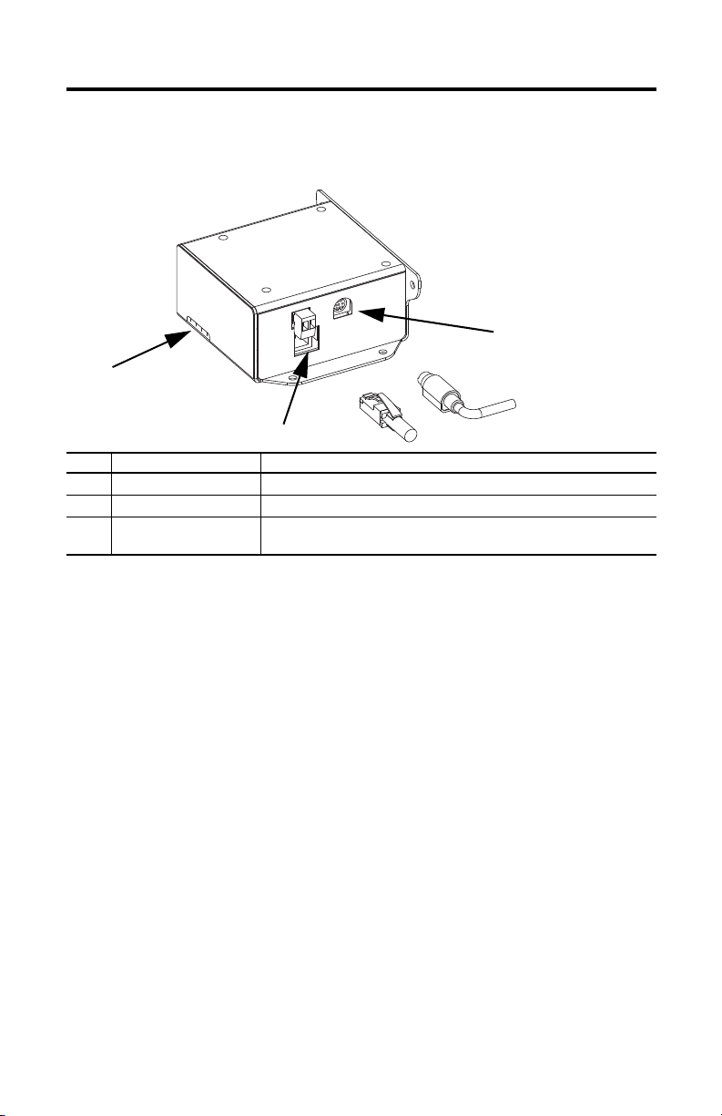
Adapter Components
The adapter has these components.
Item Part Description
1 Status Indicators Four status indicators for the DeviceNet, adapter, and network connection.
2 E3 Connector This connector is provided for the connection to the E3 Plus or the 825-P.
3 Ethernet Connector An RJ-45 connector for the Ethernet cable. The connector is CAT-5 compliant to
The E3+ and 825-P must be set to node 63 and have a communication rate of 500K (or have the
autobaud enabled). This is the default state of each of these devices.
ensure reliable data transfer on 100Base-TX Ethernet connections.
Rockwell Automation Publication 2100-IN090A-EN-P - February 2012
Page 4
4 E3 Plus EtherNet/IP Adapter
Status Indicator s
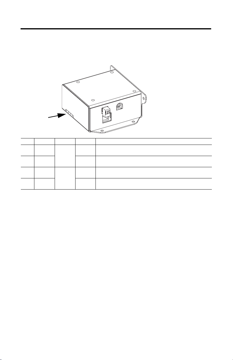
Status Indicators
The adapter uses four status indicators to report its operating status.
Item Name Color State Description
1 PORT Green Flashing Normal Operation. The adapter is establishing an I/O connection to the E3 Plus
2 MOD Steady Normal Operation. The adapter is properly connected and communicating with
3 NET A Green Flashing Normal Operation. The adapter is operating but is not transferring I/O data to a
4 NET B Steady Normal Operation. The adapter is operating and transferring I/O data to a
overload relay. It will turn steady green or red.
the E3 Plus overload relay.
controller.
controller.
Set the IP Network Address
The E3 Plus EtherNet/IP adapter is shipped with Bootstrap Protocol (BOOTP) enabled. You
can set the network Internet Protocol (IP) address by using the BOOTP/DHCP server that is
provided with RSLinx Classic software. This utility recognizes BOOTP-enabled devices and
provides an interface to configure a static IP address for each device.
To assign network parameters via the BOOTP/DHCP utility, perform this procedure.
Rockwell Automation Publication 2100-IN090A-EN-P - February 2012
1. Start the BOOTP/DHCP software.
Page 5

E3 Plus EtherNet/IP Adapter 5
2. Select Tool > Network Settings and enter the subnet mask for the network.
If appropriate for the network, enter the gateway address, primary/secondary server
addresses, and domain name.
3. Click OK.
The Request History panel displays the hardware addresses of devices issuing BOOTP
or DHCP requests.
4. Double-click the MAC address of the adapter to be configured.
The MAC address is printed on the side of the E3 Plus EtherNet/IP adapter. The format
of the hardware address resembles 00:00:BC:59:72:5A. The New Entry dialog box
appears with the module's Ethernet Address (MAC).
Rockwell Automation Publication 2100-IN090A-EN-P - February 2012
Page 6

6 E3 Plus EtherNet/IP Adapter
5. Enter the IP address for the adapter and, if appropriate, enter the host name and an
adapter description.
6. Click OK.
Once the IP address you entered shows up in the Request History panel (you may need
to cycle power to the adapter), this configuration can be permanently assigned to the
adapter.
7. To do so, highlight the adapter in the Relation List panel and click Disable
BOOTP/DHCP.
8. Confirm that the Status panel message reads, ‘[Disable BOOTP] Command successful’.
When the adapter power is recycled, it will use the assigned configuration and will not
issue a BOOTP request. If you do not click Disable BOOTP/DHCP, the adapter clears
the current IP configuration after a power cycle and will again begin sending BOOTP
requests.
Rockwell Automation Publication 2100-IN090A-EN-P - February 2012
Page 7

E3 Plus EtherNet/IP Adapter 7
Install EDS File
Before the E3 Plus EtherNet/IP adapter is configured to communicate on an EtherNet/IP
network, it must be registered to the software that configures the network, for example, RSLinx
Classic software. You can register the adapter by installing an electronic data sheet (EDS file).
For the E3 Plus EtherNet/IP adapter, you will install an EDS file for the device that is connected
to the adapter. Use the following procedure to download and reg ister the EDS file for the E3 Plus
EtherNet/IP adapter.
Download EDS file from the EDS Website
The EDS file for the device connected to the E3 Plus EtherNet/IP adapter can be found at
http://www.rockwellautomation.com/resources/eds/.
1. When the web page for the link above comes up, enter the following information.
E3 Plus Overload 825-P
Network EtherNet/IP EtherNet/IP
Device Type Motor Protector Motor Protector
Bulletin/Catalog No. 2100-ENET 2100-ENET
Major Revision (Leave Blank) (Leave Blank)
Minor Revision (Leave Blank) (Leave Blank)
Keyword (Leave Blank) (Leave Blank)
2. Select the file that relates to the E3 or 825-P module that is connected to the
2100-ENET unit.
3. In the Details & Download column for the device, select Download.
4. Click Save to save the EDS file to your personal computer.
Register the EDS File
After the EDS file has been downloaded, you need to register the EDS file with the software that
configures the EtherNet/IP network. Follow these steps to register an EDS file with RSLinx
Classic software.
1. Start the EDS Hardware Installation Tool at Start->Programs->Rockwell
Software->RSLinx->Tools.
2. Click Add to register a new device.
Rockwell Automation Publication 2100-IN090A-EN-P - February 2012
Page 8

8 E3 Plus EtherNet/IP Adapter
3. Register a single file, browse to the location of the EDS file, and click Next.
4. Click Next to accept the installation test results.
5. Click Next to accept the graphic image.
Rockwell Automation Publication 2100-IN090A-EN-P - February 2012
Page 9

E3 Plus EtherNet/IP Adapter 9
6. Click Next to register the device.
7. Click Finish.
Logix Controller I/O Messaging
RSLogix 5000 software is used to configure I/O messaging between a Logix controller and an E3
Plus EtherNet/IP adapter on an EtherNet/IP network. Follow these steps to configure a Logix
controller for I/O messaging.
1. Right-click on the EtherNet/IP scanner in I/O Configuration and select New Module
to open the Select Module Type dialog box.
2. Select Generic Ethernet Module and click OK.
3. Enter a name for the E3 Plus EtherNet/IP adapter.
The name creates a tag in RSLogix 5000 software that can be used to read and write data
from the E3 Plus EtherNet/IP adapter.
Rockwell Automation Publication 2100-IN090A-EN-P - February 2012
Page 10
10 E3 Plus EtherNet/IP Adapter
IMPORTANT
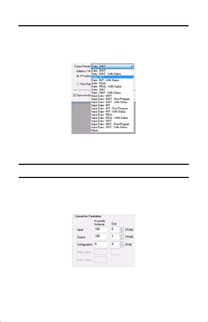
4. Select Data-INT for the Comm Format.
The Comm Format tells RSLogix 5000 software the format of the data. The Data-INT
format represents the data from the E3 Plus EtherNet/IP adapter as a field of 16-bit
values.
5. Set the Connection Parameters.
I/O data is accessed using Input Instance 100 and Output Instance 103 (for E3
standard) or 105 (for E3 Plus) by default.
If you have already changed the Input and Output Assemblies, you will need to enter those
values instead of the default values.
The size of the input connection and the output connection shall correspond to the size
of the chosen instance. For Instance 100, the size is 6. For Instances 103 and 105, the size
is 1. The E3 Plus EtherNet/IP adapter Configuration Assembly Instance is 6. Currently,
the 2100-ENET adapter does not support the configuration assembly.
Rockwell Automation Publication 2100-IN090A-EN-P - February 2012
Page 11

E3 Plus EtherNet/IP Adapter 11
Output Assembly - Instance 105
Bit Contents
0OutA
1OutB
2Fault Reset
3Not Used
4Not Used
5Remote Reset
6Not Used
7Not Used
Input Assembly - Instance 100
Byte Size Contents
2 Bytes Header information (Pad Word)
2 Bytes Header information (Pad Word)
2 Bytes Value of parame ter pointed to by parameter #61
2 Bytes Value of parame ter pointed to by parameter #62
2 Bytes Value of parame ter pointed to by parameter #63
2 Bytes Value of parame ter pointed to by parameter #64
6. Enter the IP address of the E3 Plus EtherNet/IP adapter.
7. Click Next.
Rockwell Automation Publication 2100-IN090A-EN-P - February 2012
Page 12

8. Enter a value for the time between each scan of the adapter.
Make sure Inhibit Module is not checked.
9. Click Finish to add the E3 Plus EtherNet/IP adapter to the I/O Configuration in
RSLogix 5000 software.
Additional Resources
These documents contain additional information concerning related products from Rockwell
Automation.
Resource Description
Ethernet Design Considerations
Reference Manual, publication ENET-RM002
Industrial Automation Wiring and Grounding
Guidelines, publication 1770-4.1
Product Certifications website, http://www.ab.com
You can view or download publications at http://www.rockwellautomation.com/literature/
Provides explanation of the following Ethernet concepts:
• Network Layout and Components
• Network Infrastructure Devices
• Network Infrastructure Features
• Protocol
Provides general guidelines for installing a Rockwell Automation industrial
system.
Provides declarati ons of conformity, cer tificates, and other ce rtification
details.
. To
order paper copies of technical documentation, contact your local Allen-Bradley distributor or
Rockwell Automation sales representative.
Allen-Bradley, Rockwell Software, Rockwell Automation, RSLinx, and RSLo gix 5000 are trademarks of Rockwell Automation, Inc.
Trademarks not belonging to Rockwell Automation are property of their respective companies.
Publication 2100-IN090A-EN-P - February 2012 PN-112789
Copyright © 2012 Rockwell Automation, Inc. All rights reserved. Printed in the U.S.A.
 Loading...