

Page 1

Instructions
CENTERLINE® 2100 Motor Control Centers
Joining and Splicing Vertical Sections
Application
The following instructions illustrate the recommended procedures that should
be used when joining and splicing CENTERLINE
Centers (MCCs).
For more splicing information related to specific MCCs, refer to the bus
splicing drawing included in the documentation shipped with the MCC.
ATTENTION
De-energize all power sources to the motor control center
before joining and splicing vertical sections. Failure to
de-energize all power sources can result in severe injury or
death.
®
2100 Motor Control
!
IMPORTANT
Note for NO-OX-ID - If using corrosion inhibitor on bus
bars do not get any on the bus splicing hardware. It will not
allow the hardware to be properly torqued. Damage may
occur.
Recommended Tools
Joining MCCs
1
Assorted screwdrivers, sockets (including 9/16” deep well and 5/16” sockets),
and torque wrench
NEMA 1, 1G, and 12
Physical restrictions at your installation may not allow the following sequence
to be followed exactly as stated.
1. The splice kit(s), if required, are located within a horizontal wireway or
blank unit space. On six space factor frame-mounted units, the splice kit
is within the unit. A fluorescent pink, removable label (on the outside of
the compartment) designates the location. Locate splice kit(s) and set
aside for later use.
Publication 2100-IN010D-EN-P—February 2007
Page 2

2 CENTERLINE® 2100 Motor Control Centers Joining and Splicing Vertical Sections
2. Remove top and bottom horizontal wireway covers as shown in Figure 2
and Figure 3. Remove the wood shim used in transportation from the
side of the MCC.
3. Remove top, bottom and center end closing plates, if present, exposing
joining holes (referred to as A and B in Figure 2 and Figure 3) of the
MCC. Joining holes not covered by end closing plates may contain
1/4-20 hex head thread-forming screws on the left side and removable
plastic plugs on the right side. These screws and plugs are accessible
both from within the vertical wireway and from the outside surface of
the vertical side plate and must be removed from the side plates to be
joined. See Figure 2 and Figure 3.
4. Remove the vertical wireway cover and horizontal bus splice access
cover from the sections to be joined. See Figure 1 and Figure 7.
5. Pull all “bottom entry” cables, if any are present, through the conduits
to a point where they will be accessible when the center is positioned.
6. NOTE: For NEMA 12 MCCs refer to publication 2100-IN037x-EN-P,
NEMA 12 Sealing Instructions. This publication was shipped with the
splice kit.
7. Slide sections together making sure cabinets are level and holes in side
sheets line-up with adjacent holes. See Figure 2.
NOTE: Make sure cabinets are level and pushed together, tightly. Do
not use hardware to draw cabinets together.
8. Join the two MCCs using the hardware furnished with the splice kit.
• Pass the 1/4-20 hex head thread forming screw from inside the left
MCC through joining holes (A in Figure 2 and Figure 3) and engage
the screws with the holes located in the right center. Refer to Torque
Requirements on page 15
• Pass the 1/4-20 x 5/8 hex screw from inside the left center through
joining hole (B in Figure 2 and Figure 3) and secure with the 1/4-20
steel nut. Refer to Torque Requirements on page 15
9. Secure the MCC to the floor as required by local code.
10. Inspect the interior for dust and dirt; vacuum cleaning is recommended.
Do not clean using compressed air—it contains moisture and may
blow debris into the control equipment.
Publication 2100-IN010D-EN-P—February 2007
Page 3
Removable top plate
3 CENTERLINE® 2100 Motor Control Centers Joining and Splicing Vertical Sections
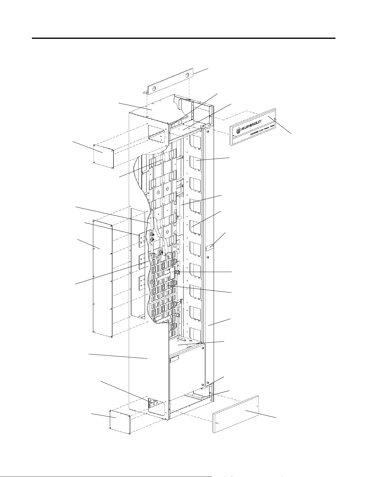
Figure 1 Typical 15” Deep MCC Construction
Lift Angle
Top Horizontal Wireway Baffles
Top Horizontal Wireway Pan
Left Hand Top End Closing Plate
(2 on 20” Deep Sections)
Horizontal and
Vertical Bus
Support
Vertical Power Bus
Horizontal Power Bus
Left Hand Center
End Closing Plate
Vertical Plug-In
Ground Bus
Top Horizontal Wireway Cover
Right Hand Unit Support
(Vertical Wireway)
Bus Splice Access Cover
Vertical Wireway Cover
Section Nameplate
Vertical to Horizontal Bus
Connection Access Cover
Vertical Bus Covers
(3 Piece Assembly)
Left Hand Side Plate Assembly
Horizontal Ground Bus,
Top or Bottom
Left Hand Bottom End Closing Plate
(2 on 20” Deep Sections)
Vertical Wireway Door
Unit Support Pan
Sealing Strap
(Top and Bottom)
Bottom Support Angle
Bottom Horizontal
Wireway Cover
Publication 2100-IN010D-EN-P—February 2007
Page 4
4 CENTERLINE® 2100 Motor Control Centers Joining and Splicing Vertical Sections
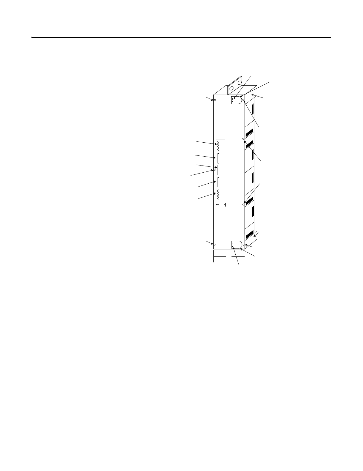
Figure 2 Example of 15” Deep MCC
Ground Bus
(Top Option*)
Top Wireway
A - Use a 1/4-20 hex head thread forming screw
B - Use a 1/4-20 x5/8 hex screw and secure with a
1/4-20 steel nut
Refer to Torque Requirements on page 15
Top Mounted
Neutral (Optional)
Phase 1 Power Bus
Phase 2 Power Bus
Phase 3 Power Bus
Bottom Mounted
Neutral (Optional)
A
Top
Horizontal
Wireway
Cover
A
A
B
7 "
A
Bottom Horizontal
Wireway Cover
A
A
15 "
Bottom Wireway
Ground Bus
(Bottom Option*)
Publication 2100-IN010D-EN-P—February 2007
* Ground bus is required. The ground bus can be in the bottom, top or bottom and top.
Page 5
20” MCC with
Standard Bus
Top Wi rew ay with
closing plate
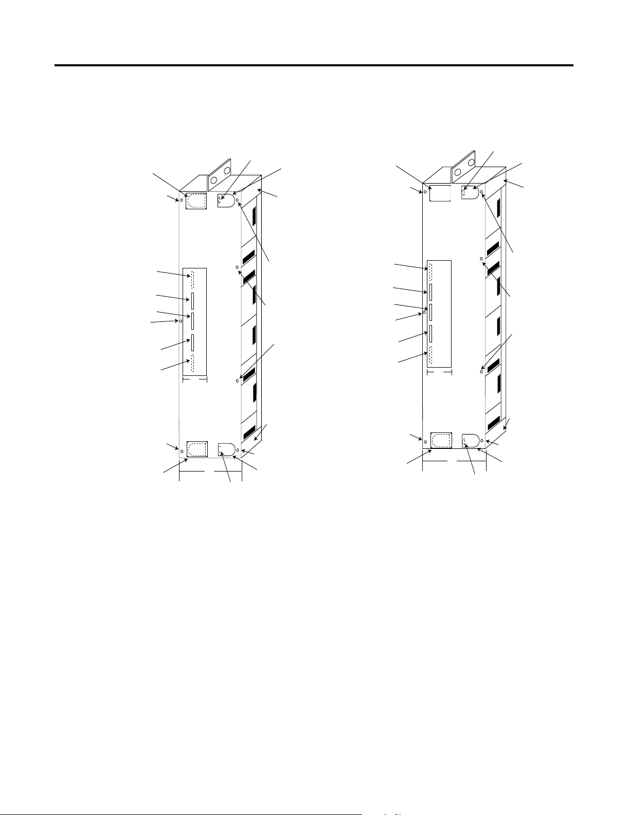
Figure 3 Example of 20” Deep MCCs
Ground Bus
(Top Option*)
Top Wireway
20” MCC with
Bumped Back Bus
Top Wireway with
closing plate
5 CENTERLINE® 2100 Motor Control Centers Joining and Splicing Vertical Sections
Ground Bus
(Top Option*)
Top Wireway
A
Top Mounted
Neutral (Optional)
Phase 1 Power Bus
Phase 2 Power Bus
B
Phase 3 Power Bus
Bottom Mounted
Neutral (Optional)
A
Bottom Wireway
with closing plate
12 "
20 "
Ground Bus
(Bottom Option*)
To p
Horizontal
Wireway
Cover
A
A
A
Bottom Horizontal
Wireway Cover
A
Bottom Wireway
A
Top Mounted
Neutral (Optional)
Phase 1 Power Bus
Phase 2 Power Bus
B
Phase 3 Power Bus
Bottom Mounted
Neutral (Optional)
A
Bottom Wireway
with closing plate
12 "
20 "
Ground Bus
(Bottom Option*)
To p
Horizontal
Wireway
Cover
A
A
A
Bottom Horizontal
Wireway Cover
A
Bottom Wireway
A - Use a 1/4-20 hex head thread forming screw
B - Use a 1/4-20 x5/8 hex screw and secure with a
1/4-20 steel nut
Refer to Torque Requirements on page 15
* Ground bus is required. The ground bus can be in the bottom, top or bottom and top.
Publication 2100-IN010D-EN-P—February 2007
Page 6

6 CENTERLINE® 2100 Motor Control Centers Joining and Splicing Vertical Sections
NEMA 3R and 4
1. Remove 3R/4 side sheet from end of section, being spliced, if present
(3R End Closing Plate). See Figure 5.
Figure 4 NEMA 3R/4 Without Side Sheet.
Holes to Tie Cabinet
Front Together
Holes to Tie
Cabinet Front
Together
Holes to Mount Cabinet Spacer
Holes to Mount Cabinet Spacer
Holes to Tie Cabinet
Front Together
Holes to Tie
Cabinet Front
To ge th er
2. Mount cabinet spacer (supplied with Splice Kit) to right hand shipping
block, using 1/4 - 20 X 3/4” thread-forming screws. (Pass threadforming screws through large hole in cabinet spacer and bolt to cabinet.)
See Figure 4 and Figure 5. Refer to Torque Requirements on page 15.
Publication 2100-IN010D-EN-P—February 2007
Page 7

Figure 5 NEMA 3R/4
Front View
Side Sheet
Drip Hood Angle
Cabinet
Spacer
7 CENTERLINE® 2100 Motor Control Centers Joining and Splicing Vertical Sections
Gasket
Side Sheet
Right Hand
Shipping Block
Gasket to be
installed in the
field
Wireway
Extension
Top View
Left Hand
Shipping Block
Wireway Extension
Cabinet Spacer
3. Remove drip hood angle from shipping block being spliced. See Figure
5.
4. Install gasket (supplied with splice kit) on back plate and top plate (If
not present on cabinet.). See Figure 5.
Publication 2100-IN010D-EN-P—February 2007
Page 8

8 CENTERLINE® 2100 Motor Control Centers Joining and Splicing Vertical Sections
5. Slide sections together making sure cabinets are level and cabinet
spacers and holes in front flange lines-up with adjacent holes. See Figure
5.
6. Install 1/4-20 X 3/4” thread-forming screws through left hand shipping
block side plate into cabinet spacer. These can be accessed through the
top and bottom horizontal wireways. Refer to Torque Requirements on
page 15.
NOTE: Make sure cabinets are level and pushed tight together. Do not
use hardware to draw sections together.
7. Install (6) 1/4-20 X 3/4” thread-forming screws in the front flange to
secure sections together. (Screws must be installed from the left
shipping block through into the right block.) This area can be accessed
by opening the NEMA 3R/4 doors. See Figure 4. Refer to Torque
Requirements on page 15.
8. Replace the drip hood angle removed in Step 3. Make sure hardware is
placed through the drip angle and clearance hole in top plate before
threading into adjacent top plate. Refer to Torque Requirements on
page 15.
Splicing MCCs
9. Install Wireway extensions. From top and bottom wireway in right hand
shipping block, insert extension through wireway opening and hook lip
on wireway opening of left hand section. Install 1/4-20 X 1/2”
thread-forming screw in wireway extension to secure to wireway
opening in right hand section. (This does not bolt into the cabinet, but is
clamped onto the wireway opening.) See Figure 5.
A main horizontal bus splice kit must be added between the horizontal bus
work of the MCCs. In addition, the neutral bus splice kit, if required, and the
ground bus splice kit must be installed to complete the splicing operation.
Refer to Splicing Procedures for instructions.
To gain access to the horizontal bus, remove the plug-in units in front of the
horizontal bus in the first vertical section of the right center.
Publication 2100-IN010D-EN-P—February 2007
Page 9

®
CENTERLINE
2100
Motor Control Centers Joining and Splicing Vertical Sections
Plug-In Unit Removal
To complete plug-in unit removal refer to publication, 2100-IN007x-EN-P,
Installing Units with Horizontal Operating Handles and publication
2100-IN014x-EN-P, Installing Units with Vertical Operating Handles.
The following is an overview of the removal process for a plug-in unit:
1. Open unit door by turning door latch a quarter turn. Door removal is
not necessary when removing a unit; however, if door removal is
desired, follow steps a-d below. Step b may be required even if the door
is not removed.
a. Open the door completely.
b. If present, remove control station housing by loosening the two (2)
captive screws located at the top and bottom of the control station
housing on the front of the unit door.
c. Remove hinge pins by sliding up with screwdriver.
d. Swing door to near closed position and lift off.
9
2. Loosen the screw type latches located at the front of the unit. Most units
have one (1) at the top and one (1) at the bottom, but units two space
factors and larger have two (2) at the top.
3. Detach necessary wiring from unit.
4. Place wire/terminal block in line with wiring clearance tunnel at lower
right of unit. Pull unit forward to unplug from bus, using the upper right
latch assembly and the lower left tab handle.
5. Remove the unit support pan. Refer to Figure 6.
a. Using a screwdriver, pry the plastic retaining clip from the right side
of the support pan. It is visible in the vertical wireway.
b. Lift right side of pan approximately four (4) inches.
c. Pull right side of pan forward to release from left rear slot.
d. Push back on left side of pan until it is free.
Publication 2100-IN010D-EN-P—February 2007
Page 10

10 CENTERLINE® 2100 Motor Control Centers Joining and Splicing Vertical Sections
Figure 6 Removal of Support Pan
Splicing Procedures
1. Remove the horizontal bus splice access cover to expose the horizontal
bus splicing. See Figure 7.
Figure 7 Bus Splice Access Cover
Bus Splice Access Cover In Place
Publication 2100-IN010D-EN-P—February 2007
Bus Splice Access Cover Removed
Page 11

CENTERLINE® 2100 Motor Control Centers Joining and Splicing Vertical Sections 11
2. Assemble splice bars to the bus work of the vertical sections as shown in
figure 8 - 13. If additional access to the splice is desired, loosen the
fastening screws and remove the bus access plate located in the vertical
wireway of the center (to the left of the splice). The horizontal bus now
is exposed to the left and right of the splice for added convenience. The
splicing kit will contain either two or four sets of hardware per splice
bar, depending on the current rating of the horizontal bus.
3. See Table A on page -14 for bus dimensions and mounting holes.
4. Tighten to torque specifications as listed in the Torque Requirements on
page -15 or tighten until the conical spring washer is flattened on the
one-piece nut and washer assembly. Do not grease or lubricate the
hardware.
5. Replace covers and plates and check all bolts and nuts for tightness.
Replace units in their respective stations.
Figure 8 600 - 1200 Amp Main Horizontal (and Neutral) Bus Splicing Detail and
Configuration Example
Main Horizontal Bus
or Neutral Bus
Two Hole Main
Horizontal Splice
One-piece assembly of
nut and conical spring
washer
Front
Splice Kit Configuration Example (Top View - 2 Sections)
Flat Washers
Bus Clamps
Main Horizontal Bus
or Neutral Bus
Refer to Table A for bus size and thickness.
Publication 2100-IN010D-EN-P—February 2007
Page 12

12 CENTERLINE®2100 Motor Control Centers Joining and Splicing Vertical Sections
Figure 9 1600 - 3000 Amp Horizontal (and Neutral) Bus Splicing Detail and
Configuration Example
Four Hole Main Horizontal Splice
Four Hole Main
Horizontal Splice
One-piece assembly of
nut and conical spring
washer
Front
Splice Kit Configuration Example (Top View - 2 Sections)
Bus Clamps
Main Horizontal Bus or
Neutral Bus
Flat Washers
2000A Main Horizontal
Bus or Neutral Bus
Main Horizontal Splice
One-piece assembly of
nut and conical spring
washer
Splice Kit Configuration Example
(Top View - 2 Sections)
Refer to Table A for bus size and thickness.
Figure 10 2000 Amp Main Breaker and 1600 Amp Horizontal Bus Splicing Detail
and Configuration Example
Main Horizontal Splice
Bus Clamps
Splice Spacer Bar
Flat Washers
Front
1600A Main Horizontal
Bus or Neutral Bus
Publication 2100-IN010D-EN-P—February 2007
Refer to Table A for bus size and thickness.
Page 13

CENTERLINE® Motor Control Centers Joining and Splicing Vertical Sections 13
Figure 11 Offset “Z” 600 - 1200 Amp Bus Splicing Detail and Configuration Example
Splice Kit Configuration Example (Top View - 3 Sections)
Refer to Table A for bus size and thickness.
Figure 12 Offset “Z” 1600 - 3000 Amp Bus Splicing Detail and Configuration
Example
Splice Kit Configuration Example (Top View - 3 Sections)
Refer to Table A for bus size and thickness.
Publication 2100-IN010D-EN-P—February 2007
Page 14

14 CENTERLINE® 2100 Motor Control Centers Joining and Splicing Vertical Sections
Figure 13 Insulated “Z” 600 - 1200 Amp Bus Splicing Detail and Configuration
Example
Main Horizontal Bus or
Neutral Bus (5” Deeper)
Main Horizontal Splice
One-piece assembly of
nut and conical spring
washer
Bus Clamps
Insulated
Splice Kit Configuration Example
(Top View - 3 Sections)
STANDARD NEMA 1, 1G, 12 & 3R SPLICE BAR INFORMATION
AMP MATERIAL QTY THICKNESS WIDTH SPLICE MTG. HOLES
Copper/Tin 1 .125”
600
Aluminum/Tin 1 .125” 4”
Copper/Tin 1 .125”
800
Aluminum/Tin 1 .1875”
Copper/Tin 1 .250”
1200
Copper/Silver 1 .250”
Front
Flat Washers
Table A Bus and Splice Bar Dimensions
3”
4” 2Copper/Silver 1 .125”
4” 2
Main Horizontal Splice or Neutral
Bus (standard location)
Refer to Table A for bus size and thickness.
2Copper/Silver 1 .125”
1600
Copper/Tin 2 .250”
Copper/Silver 2 .250”
Copper/Tin 1 .250”
2000
Copper/Silver 1 .250”
2500/
3000
Publication 2100-IN010D-EN-P—February 2007
Copper/Tin 2 .375”
Copper/Silver 2 .375”
4” 4
4” 4
1 .375”
4” 4
1 .375”
4” 4
Page 15

CENTERLINE® 2100 Motor Control Centers Joining and Splicing Vertical Sections 15
“Z” SPLICE BAR
(Used to Splice Standard Depth Bus to Bus 5” Deeper)
Note: 600-1200 AMP Bus is the same thickness as a standard Splice Bar
AMP MATERIAL QTY THICKNESS WIDTH SPLICE MTG. HOLES
1600
2000
DECIMAL FRACTION MILLIMETER DECIMAL FRACTION MILLIMETER
.125” 1/8” 3.175 .375” 3/8” 9.525
.250 1/4” 6.350 .625” 5/8” 15.875
.500” 1/2” 12.700 3” 3” 76.200
.1875” 3/16” 4.763 4” 4” 101.600
Copper/Tin 1 .500”
4” 4
Copper/Silver 1 .500”
Copper/Tin 1 .625”
4” 4
Copper/Silver 1 .625”
Table B Conversions
Torque Specifications and Table
Tighten all bus connections with a torque wrench and socket according to
intervals established by your maintenance policy. If a torque wrench is not
available, tighten until conical spring washer is flat. Do not grease or lubricate
the hardware.
Table C Torque Requirements
Description
Lug attachment bolts
1/2-13 Hardware
Horizontal to vertical bus connection
3/8-16 Hardware
Horizontal splice connection
3/8-16 Hardware
Connecting Hardware
1/4-20 Hardware
10-32 Hardware
Torque in Ft./Lb.
45 lb.-ft. ± 5 lb.-ft.
61 N-m ± 6 N-m
28 lb.-ft. ± 4 lb.-ft.
38 N-m ± 5 N-m
28 lb.-ft. ± 4lb.-ft.
38 N-m ± 5 N-m
55 lb.-in. ± 3lb.-in.
6.2 N-m ± 0.6 N-m
32 lb.-in. ± 3lb.-in.
3.6 N-m ± 0.4 N-m
Publication 2100-IN010D-EN-P—February 2007
Page 16

Supersedes Publication 2100-IN010C-EN-P— September 2006 © 2007 Rockwell International Corporation. Printed in the U.S.A.
6Publication 2100-IN010D-EN-P—February 2007 PN-25157
 Loading...