

Page 1
Installation Instructions
PowerFlex® 700L Frame 3A and 3B Input Filter
Precharge Resistor Kit (20L-RESPRE-A1)
ATTENTION: To avoid an electric shock hazard, ensure that all
power to the complete drive cabinet has been removed before
!
performing any steps of these instructions.
ATTENTION: To avoid an electric shock hazard, verify that the
voltage on the bus capacitors has completely discharged before
!
performing any work on the complete drive cabinet. After
removing power, wait 5 minutes for the power module bus
capacitors to discharge. Remove the lower front cover of the
power module. Measure the DC bus voltage at the DC+
TESTPOINT and DC- TESTPOINT sockets on the front of the
power module. The voltage must be zero.
ATTENTION: HOT surfaces can cause severe burns. Do not
touch the heatsink surface during operation of the power module.
!
After disconnecting power allow time for cooling.
Where This Kit Is Used
Table A Maximum DC Bus Capacitance with Existing Precharge
Input Voltage 400V AC 480V AC 600V AC 690V AC
Frame Size 3A 3B 3A 3B 3A 3B 3A 3B
Drive’s Internal DC Bus Capacitance (µF) 16,200 32,400 16,200 32,400 10,800 21,600 10,800 21,600
Maximum External DC Bus Capacitance (µF) 19,150 38,301 8,349 16,698 4,911 9,823 1,080 2,160
Maximum Total DC Bus Capacitance (µF) 35,350 70,701 24,549 49,098 15,711 31,423 11,880 23,760
Table B Maximum DC Bus Capacitance with Precharge Kit Plus Existing Precharge
Input Voltage 400V AC 480V AC 600V AC 690V AC
Frame Size 3A 3B 3A 3B 3A 3B 3A 3B
Drive’s Internal DC Bus Capacitance (µF) 16,200 32,400 16,200 32,400 10,800 21,600 10,800 21,600
Maximum External DC Bus Capacitance (µF) 89,851 109,002 57,447 65,796 36,334 41,245 24,840 25,920
Maximum Total DC Bus Capacitance (µF) 106,051 141,402 73,647 98,196 47,134 62,845 35,640 47,520
ATTENTION: The complete drive cabinet contains ESD
(Electrostatic Discharge) sensitive parts and assemblies. Static
!
control precautions are required when installing, testing,
servicing or repairing the complete drive. Component damage
may result if ESD control procedures are not followed. If you are
not familiar with static control procedures, refer to Allen-Bradley
publication 8000-4.5.2, “Guarding Against Electrostatic
Damage” or any other applicable ESD protection handbook.
This kit can only be used with PowerFlex 700L Frame 3A and 3B complete
drives. It is used to increase the precharge power capacity of the drive. This
kit may be required when powering another drive from the DC bus of a
Frame 3A or 3B complete drive. Only one kit per drive is permitted. See the
tables below for comparisons of maximum DC bus capacitance.
Page 2

2 PowerFlex® 700L Frame 3A and 3B Input Filter Precharge Resistor Kit (20L-RESPRE-A1)
Parameter 162 - [Capacitance] of the PowerFlex 700L Active Converter
must be set to the total DC bus capacitance of the PowerFlex 700L complete
drive plus the other drives connected to the DC bus.
What This Kit Includes
Tools That You Need
What You Need to Do
• Precharge Resistor Plate Assembly
• Four (4) M6 x 16 mm (0.63 in.) long hex head Taptite
Taptite is a registered trademark of REMINC (Research Engineering & Manufacturing Inc.)
Note: The customer must provide wire, lugs, and hardware.
• 10 mm socket
• Phillips
• Phillips
• Torque wrench
• Wire stripper
Phillips is a registered trademark of Phillips Screw Company.
To install the PowerFlex® 700L Frame 3A and 3B Precharge Resistor Kit:
❐ Step 1: Remove power from the complete drive.
❐ Step 2: Drill installation holes (only required for input filter panel
❐ Step 3: Mount the kit.
®
#1 screwdriver
®
#2 screwdriver
without holes).
®
screws
❐ Step 4: Wire the kit.
Page 3
PowerFlex® 700L Frame 3A and 3B Input Filter Precharge Resistor Kit (20L-RESPRE-A1) 3
Step 1: Removing Power from the Complete Drive
ATTENTION: To avoid an electric shock hazard, verify that the
voltage on the bus capacitors has completely discharged before
!
performing any work on the complete drive cabinet. After
removing power, wait 5 minutes for the power module bus
capacitors to discharge. Remove the lower front cover of the
power module. Measure the DC bus voltage at the DC+
TESTPOINT and DC- TESTPOINT sockets on the front of the
power module. The voltage must be zero.
Remove power before making or breaking cable connections.
When you remove or insert a cable connector with power
applied, an electrical arc may occur, which can cause personal
injury or property damage by:
• sending an erroneous signal to your system’s field devices,
causing unintended machine motion
• causing an explosion in a hazardous environment
Electrical arcing causes excessive wear to contacts on both the
module and its mating connector. Worn contacts may create
electrical resistance.
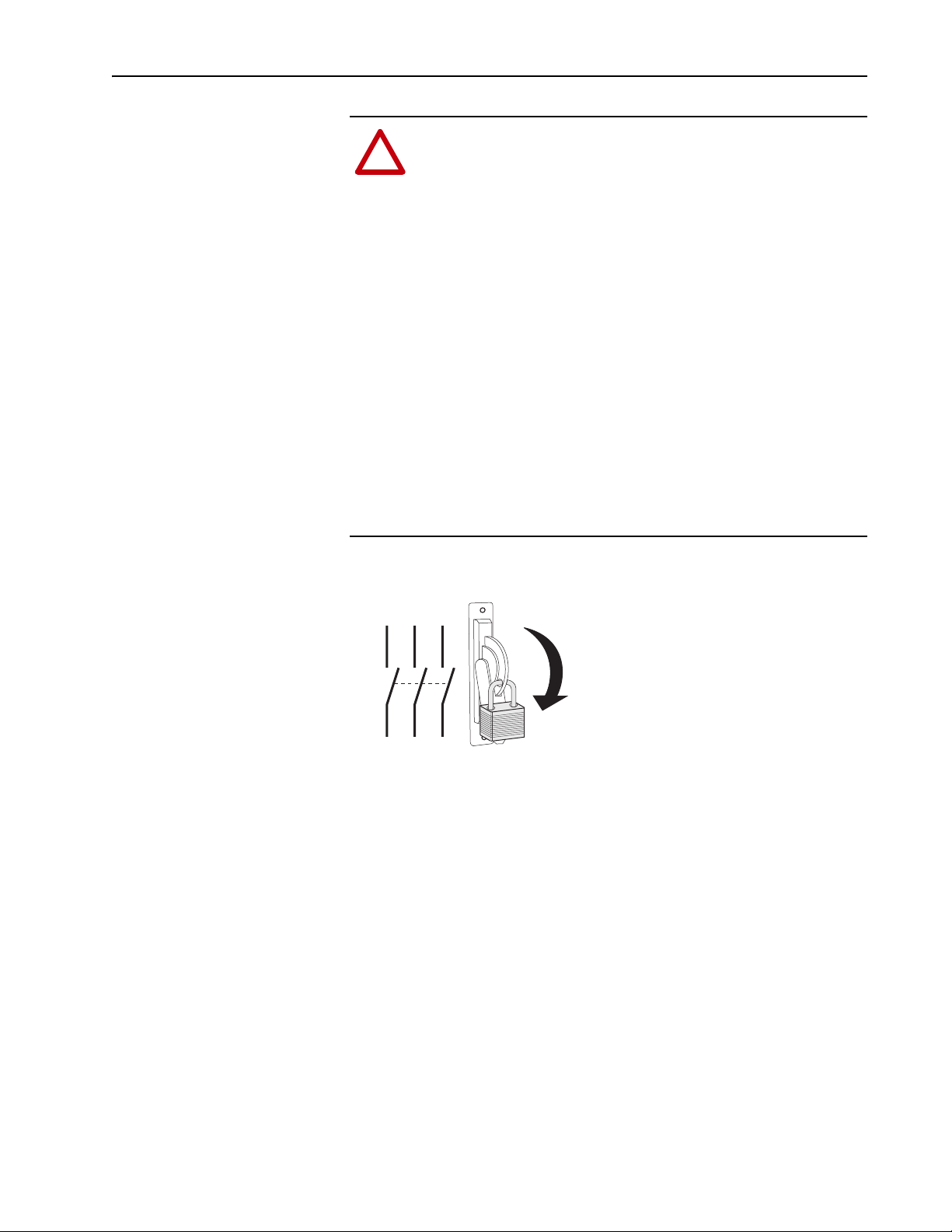
1. Turn off and lock out complete drive input power. Wait 5 minutes.
L1 L2 L3
2. Verify that there is no voltage at the complete drive’s input power
terminals.
3. Remove the lower front cover of the power module. Loosen the two (2)
captive screws and pull the cover off the power module. Set the cover
aside to be reinstalled later.
4. Measure the DC bus voltage at the DC+ TESTPOINT and DC-
TESTPOINT sockets on the front of the power module chassis. The
voltage must be zero.
I
O
Page 4

4 PowerFlex® 700L Frame 3A and 3B Input Filter Precharge Resistor Kit (20L-RESPRE-A1)
Step 2: Drilling Installation Holes (only required for input filter panel without pre-drilled holes)
ATTENTION: To avoid damaging critical electrical
components behind the input filter divider panel when drilling
!
holes, set the drill bit length to a maximum of 25.4 mm (1.0 in.).
If the input filter panel has no pre-drilled holes, drill four (4) mounting
holes at the dimensions shown in the drawings below in the right side panel
of the input filter. Use a #16 (4.5 mm/0.177 inch diameter) twist drill bit to
make the required diameter holes for the M6 x 16 mm (0.63 in.) long Taptite
hex head screws provided in the kit. Take care to prevent metal chips from
entering the enclosure.
Dimensions are in millimeters (inches).
Frame 3A
Right Side View
431.8 (17.00)
Frame 3B
Right Side View
142.9 (5.63)
247.6 (9.75)
166.2
(6.54)
40.0 (1.57)
142.9 (5.63)
232.3
(9.15)
431.8
(17.00)
Page 5

PowerFlex® 700L Frame 3A and 3B Input Filter Precharge Resistor Kit (20L-RESPRE-A1) 5
Step 3: Mounting the Kit
1. Orient the kit vertically (Frame 3A) or horizontally (Frame 3B) on the
right side panel of the input filter as shown in the drawings below.
Right Side View
Grommet for Routing Kit Wiring
Frame 3A Precharge Resistor Kit (shown installed)
Right Side View
Grommet for Routing Kit Wiring
Frame 3B Precharge Resistor Kit (shown installed)
Page 6

6 PowerFlex® 700L Frame 3A and 3B Input Filter Precharge Resistor Kit (20L-RESPRE-A1)
2. Mount the kit using the four (4) new M6 x 16 mm (0.63 in.) long
Screw, Phillips Slot Head
M5, 3 Places
Screw, Phillips Slot Head
#6, 3 Places
Taptite
shown in the drawing below.
®
Phillips #2
3.9 N-m
(35 lb.-in.)
Phillips #1
1.0 N-m
(9 lb.-in.)
hex head screws from the kit. Tighten the screws to the torque
Frame 3A
Screw, Taptite Hex Head
M6 x 16 mm Long
4 Places
10 mm
5.4 N-m
(48 lb.-in.)
Frame 3B
Screw, Phillips Slot Head
M5, 3 Places
Phillips #2
3.9 N-m
(35 lb.-in.)
Screw, Taptite Hex Head
M6 x 16 mm Long
4 Places
10 mm
5.4 N-m
(48 lb.-in.)
Screw, Phillips Slot Head
#6, 3 Places
Phillips #1
1.0 N-m
(9 lb.-in.)
Page 7

PowerFlex® 700L Frame 3A and 3B Input Filter Precharge Resistor Kit (20L-RESPRE-A1) 7
Step 4: Wiring the Kit
Connect the kit’s resistors in parallel with the existing precharge resistors in
the input filter. Wire the kit as follows:
From Kit To Input Filter
TB5-1 K1A-L2
TB5-2 K1B-L2
TB5-4 K1C-L2
FU13 K1A-T2
FU14 K1B-T2
FU15 K1C-T2
On the kit side, tighten the screws to the torque shown in the drawings of
Step 3. Use tie-wraps to bundle the wiring. Route the wiring through the
grommet hole shown in the drawing on page 5. On the input filter side, use
the existing M8 hex head screws on the contactors as shown in the drawings
below and ring lugs (not provided) for wiring connections. Tighten the
screws on the contactors to 14.9 N-m (132 lb.-in.).
L1 L2 L3
To Kit TB5-1 To Kit TB5-2
L1 L2 L3
L1 L2 L3
To Kit TB5-4
Frame 3A
Frame 3B
K1A K1B K1C
T1 T2
T3
To Kit FU13
L1 L2 L3
K1A
T1 T2
T1 T2 T3
To Kit FU14
To Kit TB5-1 To Kit TB5-2 To Kit TB5-4
L1 L2 L3
K1B
T3
T1 T2
T3
L1 L2 L3
T1 T2
T1 T2 T3
To Kit FU15
K1C
T3
To Kit FU13 To Kit FU14 To Kit FU15
Page 8

A
A
U.S. Allen-Bradley Drives Technical Support - Tel: (1) 262.512.8176, Fax: (1) 262.512.2222, Email: support@drives.ra.rockwell.com, Online: www.ab.com/support/abdrives
www.rockwellautomation.com
Power, Control and Information Solutions Headquarters
mericas: Rockwell Automation, 1201 South Second Street, Milwaukee, WI 53204-2496 USA, Tel: (1) 414.382.2000, Fax: (1) 414.382.4444
Europe/Middle East/Africa: Rockwell Automation, Vorstlaan/Boulevard du Souverain 36, 1170 Brussels, Belgium, Tel: (32) 2 663 0600, Fax: (32) 2 663 0640
sia Pacific: Rockwell Automation, Level 14, Core F, Cyberport 3, 100 Cyberport Road, Hong Kong, Tel: (852) 2887 4788, Fax: (852) 2508 1846
Publication 20L-IN010A-EN-P – September, 2007 P/N 367549-P01
Copyright © 2007 Rockwell Automation, Inc. All rights reserved. Printed in USA.
 Loading...