

Page 1
Safety Reference Manual
Kinetix 6200 and Kinetix 6500 Safe Speed Monitoring
Multi-axis Servo Drives
Catalog Numbers 2094-SE02F-M00-S1, 2094-EN02D-M01-S1
Original Instructions
Page 2
Important User Information
IMPORTANT
Solid-state equipment has operational characteristics differing from those of electromechanical equipment. Safety
Guidelines for the Application, Installation and Maintenance of Solid State Controls (publication SGI-1.1
your local Rockwell Automation sales office or online at http://www.rockwellautomation.com/literature/
important differences between solid-state equipment and hard-wired electromechanical devices. Because of this difference,
and also because of the wide variety of uses for solid-state equipment, all persons responsible for applying this equipment
must satisfy themselves that each intended application of this equipment is acceptable.
In no event will Rockwell Automation, Inc. be responsible or liable for indirect or consequential damages resulting from the
use or application of this equipment.
The examples and diagrams in this manual are included solely for illustrative purposes. Because of the many variables and
requirements associated with any particular installation, Rockwell Automation, Inc. cannot assume responsibility or
liability for actual use based on the examples and diagrams.
No patent liability is assumed by Rockwell Automation, Inc. with respect to use of information, circuits, equipment, or
software described in this manual.
Reproduction of the contents of this manual, in whole or in part, without written permission of Rockwell Automation,
Inc., is prohibited.
Throughout this manual, when necessary, we use notes to make you aware of safety considerations.
available from
) describes some
WARNING: Identifies information about practices or circumstances that can cause an explosion in a hazardous environment,
which may lead to personal injury or death, property damage, or economic loss.
ATTENTION: Identifies information about practices or circumstances that can lead to personal injury or death, property
damage, or economic loss. Attentions help you identify a hazard, avoid a hazard, and recognize the consequence.
SHOCK HAZARD: Labels may be on or inside the equipment, for example, a drive or motor, to alert people that dangerous
voltage may be present.
BURN HAZARD: Labels may be on or inside the equipment, for example, a drive or motor, to alert people that surfaces may
reach dangerous temperatures.
Identifies information that is critical for successful application and understanding of the product.
Allen-Bradley, Guardmaster, Kinetix, Logix5000, MP-Series, PowerFlex, RSLogix, Rockwell Software, Rockwell Automation, Studio 5000, and TechConnect are trademarks of Rockwell Automation, Inc.
Trademarks not belonging to Rockwell Automation are property of their respective companies.
Page 3

This manual contains new and updated information.
Summary of Changes
New and Updated Information
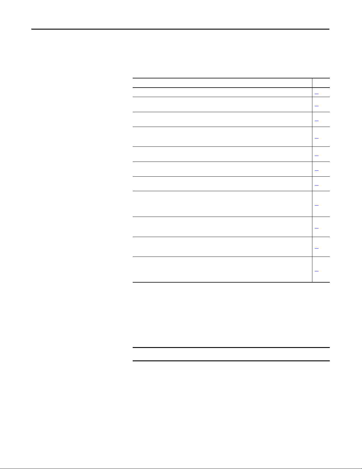
This table contains the changes made to this revision.
Top ic Pa ge
Studio 5000™ Logix Designer application is the rebranding of RSLogix™ 5000 software. References to
RSLogix 5000 software have been replaced by the Logix Designer application.
Updated descriptive text in Safety Certification and Important Safety Considerations for consistency
with the text used in other Kinetix® servo drive safety documentation.
Added European Union Directives
Corrected the IOD-0 pin description and signal name. 27
Added IMPORTANT text and Response Time Settings table 47
Added descriptive text and example formulas to enhance the understanding of Safe Stop 1 and 2. 56…59
Deceleration Rate removed from Safe Stop Parameter tables throughout this publication. –
Corrected wiring to IOD-27 and IOD-28 in Figure 28
Added IMPORTANT text to Editing the Configuration
Added IMPORTANT text to Example Application.121
Replaced the Safe Stop tab screen capture. 129
Added bullet statement to FEEDBACK 1 in the Safe State Faults
to chapter 1. 16
.90
.118
table. 135
12
13 and 14
Rockwell Automation Publication 2094-RM001C-EN-P - May 2013 3
Page 4

Summary of Changes
Notes:
4 Rockwell Automation Publication 2094-RM001C-EN-P - May 2013
Page 5

Table of Contents
Preface
About This Publication. . . . . . . . . . . . . . . . . . . . . . . . . . . . . . . . . . . . . . . . . . . 11
Audience . . . . . . . . . . . . . . . . . . . . . . . . . . . . . . . . . . . . . . . . . . . . . . . . . . . . . . . . 11
Conventions. . . . . . . . . . . . . . . . . . . . . . . . . . . . . . . . . . . . . . . . . . . . . . . . . . . . . 11
Terminology. . . . . . . . . . . . . . . . . . . . . . . . . . . . . . . . . . . . . . . . . . . . . . . . . . . . . 11
Studio 5000 Environment . . . . . . . . . . . . . . . . . . . . . . . . . . . . . . . . . . . . . . . . 12
Additional Resources . . . . . . . . . . . . . . . . . . . . . . . . . . . . . . . . . . . . . . . . . . . . . 12
Chapter 1
Safety Concept
About the Kinetix 6200 and
Kinetix 6500 Safe Speed
Monitoring Features
Safety Certification. . . . . . . . . . . . . . . . . . . . . . . . . . . . . . . . . . . . . . . . . . . . . . . 13
Important Safety Considerations . . . . . . . . . . . . . . . . . . . . . . . . . . . . . . 14
Safety Category 4 Performance Definition. . . . . . . . . . . . . . . . . . . . . . 14
Stop Category Definitions . . . . . . . . . . . . . . . . . . . . . . . . . . . . . . . . . . . . 15
Performance Level and Safety Integrity Level (SIL) CL3 . . . . . . . . . 15
European Union Directives . . . . . . . . . . . . . . . . . . . . . . . . . . . . . . . . . . . . . . . 16
CE Conformity . . . . . . . . . . . . . . . . . . . . . . . . . . . . . . . . . . . . . . . . . . . . . . 16
EMC Directive. . . . . . . . . . . . . . . . . . . . . . . . . . . . . . . . . . . . . . . . . . . . . . . 16
Low Voltage Directive . . . . . . . . . . . . . . . . . . . . . . . . . . . . . . . . . . . . . . . . 16
Functional Proof Tests . . . . . . . . . . . . . . . . . . . . . . . . . . . . . . . . . . . . . . . . . . . 16
PFD and PFH Definitions . . . . . . . . . . . . . . . . . . . . . . . . . . . . . . . . . . . . . . . . 17
PFD and PFH Data . . . . . . . . . . . . . . . . . . . . . . . . . . . . . . . . . . . . . . . . . . . . . . 17
Safe State . . . . . . . . . . . . . . . . . . . . . . . . . . . . . . . . . . . . . . . . . . . . . . . . . . . . . . . . 17
Safety Reaction Time. . . . . . . . . . . . . . . . . . . . . . . . . . . . . . . . . . . . . . . . . . . . . 18
Considerations for Safety Ratings. . . . . . . . . . . . . . . . . . . . . . . . . . . . . . . . . . 18
Considerations for Single-encoder Applications. . . . . . . . . . . . . . . . . 18
Understanding Commutation. . . . . . . . . . . . . . . . . . . . . . . . . . . . . . . . . 19
Chapter 2
Safety Functions . . . . . . . . . . . . . . . . . . . . . . . . . . . . . . . . . . . . . . . . . . . . . . . . . 21
Operation Modes . . . . . . . . . . . . . . . . . . . . . . . . . . . . . . . . . . . . . . . . . . . . 22
Disabled Mode. . . . . . . . . . . . . . . . . . . . . . . . . . . . . . . . . . . . . . . . . . . . . . . 22
Lock Monitoring . . . . . . . . . . . . . . . . . . . . . . . . . . . . . . . . . . . . . . . . . . . . . 23
Safe Maximum Speed, Safe Maximum Acceleration, and
Safe Direction Monitoring . . . . . . . . . . . . . . . . . . . . . . . . . . . . . . . . . . . . 23
Hardware Features . . . . . . . . . . . . . . . . . . . . . . . . . . . . . . . . . . . . . . . . . . . . . . . 24
Installation and Wiring
Chapter 3
General Safety Information . . . . . . . . . . . . . . . . . . . . . . . . . . . . . . . . . . . . . . . 25
Power Supply Requirements . . . . . . . . . . . . . . . . . . . . . . . . . . . . . . . . . . . . . . 26
Wiring the Safety Connections. . . . . . . . . . . . . . . . . . . . . . . . . . . . . . . . . . . . 26
Terminal Connections . . . . . . . . . . . . . . . . . . . . . . . . . . . . . . . . . . . . . . . . . . . 27
Compatible Encoders . . . . . . . . . . . . . . . . . . . . . . . . . . . . . . . . . . . . . . . . . . . . 28
Rockwell Automation Publication 2094-RM001C-EN-P - May 2013 5
Page 6

Table of Contents
Chapter 4
Speed Monitoring I/O Signals
General Device and Feedback
Monitoring Configuration
Inputs . . . . . . . . . . . . . . . . . . . . . . . . . . . . . . . . . . . . . . . . . . . . . . . . . . . . . . . . . . . 29
Safe Stop Input (SS_In) . . . . . . . . . . . . . . . . . . . . . . . . . . . . . . . . . . . . . . . 32
Safe Limited Speed Input (SLS_In) . . . . . . . . . . . . . . . . . . . . . . . . . . . . 32
Door Monitor Input (DM_In) . . . . . . . . . . . . . . . . . . . . . . . . . . . . . . . . 32
Enabling Switch Monitor Input (ESM_In) . . . . . . . . . . . . . . . . . . . . . 33
Lock Monitor Input (LM_In) . . . . . . . . . . . . . . . . . . . . . . . . . . . . . . . . . 33
Reset Input (Reset_In) . . . . . . . . . . . . . . . . . . . . . . . . . . . . . . . . . . . . . . . . 34
Outputs . . . . . . . . . . . . . . . . . . . . . . . . . . . . . . . . . . . . . . . . . . . . . . . . . . . . . . . . . 35
Safe Stop Output (SS_Out) . . . . . . . . . . . . . . . . . . . . . . . . . . . . . . . . . . . 35
Safe Limited Speed Output (SLS_Out). . . . . . . . . . . . . . . . . . . . . . . . . 36
Door Control Output (DC_Out) . . . . . . . . . . . . . . . . . . . . . . . . . . . . . 38
Chapter 5
Cascaded Configuration . . . . . . . . . . . . . . . . . . . . . . . . . . . . . . . . . . . . . . . . . . 41
Operation Mode . . . . . . . . . . . . . . . . . . . . . . . . . . . . . . . . . . . . . . . . . . . . . . . . . 42
Reset Type. . . . . . . . . . . . . . . . . . . . . . . . . . . . . . . . . . . . . . . . . . . . . . . . . . . . . . . 42
Overspeed Response Time . . . . . . . . . . . . . . . . . . . . . . . . . . . . . . . . . . . . . . . . 43
Speed Resolution Accuracy for Rotary Systems . . . . . . . . . . . . . . . . . . 43
Speed Resolution Accuracy for Linear Systems . . . . . . . . . . . . . . . . . . 45
General Parameter List. . . . . . . . . . . . . . . . . . . . . . . . . . . . . . . . . . . . . . . . . . . . 48
Feedback Monitoring. . . . . . . . . . . . . . . . . . . . . . . . . . . . . . . . . . . . . . . . . . . . . 49
Feedback Polarity. . . . . . . . . . . . . . . . . . . . . . . . . . . . . . . . . . . . . . . . . . . . . 49
Single Encoder . . . . . . . . . . . . . . . . . . . . . . . . . . . . . . . . . . . . . . . . . . . . . . . 50
Dual Encoders. . . . . . . . . . . . . . . . . . . . . . . . . . . . . . . . . . . . . . . . . . . . . . . . 50
Feedback Voltage Monitoring Range . . . . . . . . . . . . . . . . . . . . . . . . . . . 53
Feedback Fault . . . . . . . . . . . . . . . . . . . . . . . . . . . . . . . . . . . . . . . . . . . . . . . 53
Feedback Parameter List . . . . . . . . . . . . . . . . . . . . . . . . . . . . . . . . . . . . . . . . . . 54
Chapter 6
Safe Stop and Safe Stop with
Door Monitoring Modes
6 Rockwell Automation Publication 2094-RM001C-EN-P - May 2013
Safe Stop Mode . . . . . . . . . . . . . . . . . . . . . . . . . . . . . . . . . . . . . . . . . . . . . . . . . . 55
Stop Categories. . . . . . . . . . . . . . . . . . . . . . . . . . . . . . . . . . . . . . . . . . . . . . . 56
Standstill Speed and Position Tolerance . . . . . . . . . . . . . . . . . . . . . . . . 61
Deceleration Monitoring. . . . . . . . . . . . . . . . . . . . . . . . . . . . . . . . . . . . . . 62
Safe Stop Reset . . . . . . . . . . . . . . . . . . . . . . . . . . . . . . . . . . . . . . . . . . . . . . . 63
Door Control . . . . . . . . . . . . . . . . . . . . . . . . . . . . . . . . . . . . . . . . . . . . . . . . 64
Lock Monitoring . . . . . . . . . . . . . . . . . . . . . . . . . . . . . . . . . . . . . . . . . . . . . 66
Safe Stop Parameter List . . . . . . . . . . . . . . . . . . . . . . . . . . . . . . . . . . . . . . . . . . 66
Safe Stop Wiring Example. . . . . . . . . . . . . . . . . . . . . . . . . . . . . . . . . . . . . . . . . 68
Safe Stop with Door Monitoring Mode . . . . . . . . . . . . . . . . . . . . . . . . . . . . 68
Lock Monitoring . . . . . . . . . . . . . . . . . . . . . . . . . . . . . . . . . . . . . . . . . . . . . 68
SS Reset. . . . . . . . . . . . . . . . . . . . . . . . . . . . . . . . . . . . . . . . . . . . . . . . . . . . . . 69
Safe Stop with Door Monitoring Parameter List . . . . . . . . . . . . . . . . . . . . 69
Safe Stop with Door Monitoring Wiring Example. . . . . . . . . . . . . . . . . . . 69
Page 7

Chapter 7
Table of Contents
Safe Limited Speed (SLS) Modes
Safe Limited Speed (SLS) Mode . . . . . . . . . . . . . . . . . . . . . . . . . . . . . . . . . . . 71
Safe Limited Speed Reset. . . . . . . . . . . . . . . . . . . . . . . . . . . . . . . . . . . . . . 73
Safe Limited Speed Parameter List. . . . . . . . . . . . . . . . . . . . . . . . . . . . . . . . . 74
Safe Limited Speed Wiring Example . . . . . . . . . . . . . . . . . . . . . . . . . . . . . . . 75
Safe Limited Speed with Door Monitoring Mode . . . . . . . . . . . . . . . . . . . 75
Safe Limited Speed Reset. . . . . . . . . . . . . . . . . . . . . . . . . . . . . . . . . . . . . . 76
SLS with Door Monitoring Parameter List . . . . . . . . . . . . . . . . . . . . . . . . . 77
SLS with Door Monitoring Wiring Example . . . . . . . . . . . . . . . . . . . . . . . 77
Safe Limited Speed with Enabling Switch Monitoring Mode. . . . . . . . . 78
Safe Stop Reset (SS Reset) and Safe Limited Speed Reset
(SLS Reset) . . . . . . . . . . . . . . . . . . . . . . . . . . . . . . . . . . . . . . . . . . . . . . . . . . 78
SLS with Enabling Switch Monitoring Parameter List. . . . . . . . . . . . . . . 79
SLS with Enabling Switch Monitoring Wiring Example . . . . . . . . . . . . . 79
Safe Limited Speed with Door Monitoring and Enabling Switch
Monitoring Mode. . . . . . . . . . . . . . . . . . . . . . . . . . . . . . . . . . . . . . . . . . . . . . . . 80
Behavior During SLS Monitoring. . . . . . . . . . . . . . . . . . . . . . . . . . . . . . 81
Behavior While SLS Monitoring is Inactive. . . . . . . . . . . . . . . . . . . . . 81
Behavior During SLS Monitoring Delay. . . . . . . . . . . . . . . . . . . . . . . . 81
Safe Stop Reset (SS Reset) and Safe Limited Speed Reset
(SLS Reset) . . . . . . . . . . . . . . . . . . . . . . . . . . . . . . . . . . . . . . . . . . . . . . . . . . 82
SLS with Door Monitoring and Enabling Switch Monitoring
Parameter List . . . . . . . . . . . . . . . . . . . . . . . . . . . . . . . . . . . . . . . . . . . . . . . . . . . 82
SLS with Door Monitoring and Enabling Switch Monitoring
Wiring Example . . . . . . . . . . . . . . . . . . . . . . . . . . . . . . . . . . . . . . . . . . . . . . . . . 83
Safe Limited Speed Status Only Mode . . . . . . . . . . . . . . . . . . . . . . . . . . . . . 84
Speed Hysteresis . . . . . . . . . . . . . . . . . . . . . . . . . . . . . . . . . . . . . . . . . . . . . 85
SLS Status Only Parameter List . . . . . . . . . . . . . . . . . . . . . . . . . . . . . . . . . . . 85
SLS Status Only Wiring Examples . . . . . . . . . . . . . . . . . . . . . . . . . . . . . . . . . 86
Slave Modes for Multi-axis Cascaded
Systems
Chapter 8
Cascaded Configurations . . . . . . . . . . . . . . . . . . . . . . . . . . . . . . . . . . . . . . . . . 89
Slave, Safe Stop Mode . . . . . . . . . . . . . . . . . . . . . . . . . . . . . . . . . . . . . . . . . . . . 91
Slave, Safe Stop Parameter List . . . . . . . . . . . . . . . . . . . . . . . . . . . . . . . . . . . . 91
Slave, Safe Stop Wiring Examples. . . . . . . . . . . . . . . . . . . . . . . . . . . . . . . . . . 93
Slave, Safe Limited Speed Mode . . . . . . . . . . . . . . . . . . . . . . . . . . . . . . . . . . . 96
Slave, Safe Limited Speed Parameters . . . . . . . . . . . . . . . . . . . . . . . . . . . . . . 96
Slave, Safe Limited Speed Wiring Examples . . . . . . . . . . . . . . . . . . . . . . . . 97
Slave, Safe Limited Speed Status Only Mode . . . . . . . . . . . . . . . . . . . . . . . 99
Slave, Safe Limited Speed Status Only Parameter List . . . . . . . . . . . . . . . 99
Slave, Safe Limited Speed Status Only Wiring Examples . . . . . . . . . . . . 100
Multi-axis Connections. . . . . . . . . . . . . . . . . . . . . . . . . . . . . . . . . . . . . . . . . . 101
Rockwell Automation Publication 2094-RM001C-EN-P - May 2013 7
Page 8

Table of Contents
Chapter 9
Safe Maximum Speed and Direction
Monitoring
Safety Configuration and Verification
Safe Maximum Speed (SMS) Monitoring. . . . . . . . . . . . . . . . . . . . . . . . . . 103
Safe Maximum Acceleration (SMA) Monitoring . . . . . . . . . . . . . . . . . . . 106
Safe Direction Monitoring (SDM). . . . . . . . . . . . . . . . . . . . . . . . . . . . . . . . 108
Max Speed, Max Accel, and Direction Monitoring Parameter List . . . 110
Chapter 10
Safety Configuration . . . . . . . . . . . . . . . . . . . . . . . . . . . . . . . . . . . . . . . . . . . . 111
Configuration Signature ID . . . . . . . . . . . . . . . . . . . . . . . . . . . . . . . . . . 111
Safety-lock . . . . . . . . . . . . . . . . . . . . . . . . . . . . . . . . . . . . . . . . . . . . . . . . . . 112
Set and Change a Password . . . . . . . . . . . . . . . . . . . . . . . . . . . . . . . . . . . 112
Resetting the Password. . . . . . . . . . . . . . . . . . . . . . . . . . . . . . . . . . . . . . . 113
Resetting the Configuration . . . . . . . . . . . . . . . . . . . . . . . . . . . . . . . . . . 113
Basics of Application Development and Testing . . . . . . . . . . . . . . . . . . . 114
Commissioning the System. . . . . . . . . . . . . . . . . . . . . . . . . . . . . . . . . . . . . . . 114
Specifying the Safety Configuration . . . . . . . . . . . . . . . . . . . . . . . . . . . 115
Configure the Safe Speed Monitoring Drive . . . . . . . . . . . . . . . . . . . 116
Project Verification Test . . . . . . . . . . . . . . . . . . . . . . . . . . . . . . . . . . . . . 116
Confirm the Project . . . . . . . . . . . . . . . . . . . . . . . . . . . . . . . . . . . . . . . . . 117
Safety Validation . . . . . . . . . . . . . . . . . . . . . . . . . . . . . . . . . . . . . . . . . . . . 117
Verifying the Signature and Lock in the Safe Speed Monitor
Drive . . . . . . . . . . . . . . . . . . . . . . . . . . . . . . . . . . . . . . . . . . . . . . . . . . . . . . . 118
Editing the Configuration. . . . . . . . . . . . . . . . . . . . . . . . . . . . . . . . . . . . . . . . 118
Safety Configuration Example
Troubleshooting the Safe Speed
Monitoring Drive
Chapter 11
Example Application . . . . . . . . . . . . . . . . . . . . . . . . . . . . . . . . . . . . . . . . . . . . 121
Use the Initial Safety Main Tab Commands . . . . . . . . . . . . . . . . . . . 123
Configure the Safety Tab Parameters . . . . . . . . . . . . . . . . . . . . . . . . . . 126
Feedback Tab Settings . . . . . . . . . . . . . . . . . . . . . . . . . . . . . . . . . . . . . . . 127
Configure the Input Tab Parameters . . . . . . . . . . . . . . . . . . . . . . . . . . 128
Configure the Safe Stop Tab Parameters. . . . . . . . . . . . . . . . . . . . . . . 129
Configure Safe Limited Speed Tab Parameters . . . . . . . . . . . . . . . . . 130
Configure Safe Max Speed Tab Parameters . . . . . . . . . . . . . . . . . . . . 131
Chapter 12
Status Indicators . . . . . . . . . . . . . . . . . . . . . . . . . . . . . . . . . . . . . . . . . . . . . . . . 133
Nonrecoverable Faults . . . . . . . . . . . . . . . . . . . . . . . . . . . . . . . . . . . . . . . . . . . 133
Fault Recovery . . . . . . . . . . . . . . . . . . . . . . . . . . . . . . . . . . . . . . . . . . . . . . . . . . 133
Input and Output Faults . . . . . . . . . . . . . . . . . . . . . . . . . . . . . . . . . . . . . . . . . 134
Fault Codes and Descriptions . . . . . . . . . . . . . . . . . . . . . . . . . . . . . . . . . . . . 134
Fault Reactions. . . . . . . . . . . . . . . . . . . . . . . . . . . . . . . . . . . . . . . . . . . . . . . . . . 137
Safe State Faults . . . . . . . . . . . . . . . . . . . . . . . . . . . . . . . . . . . . . . . . . . . . . 137
Stop Category Faults and Fault While Stopping Faults. . . . . . . . . . 137
Status Attributes . . . . . . . . . . . . . . . . . . . . . . . . . . . . . . . . . . . . . . . . . . . . . . . . 138
Guard Status Attributes . . . . . . . . . . . . . . . . . . . . . . . . . . . . . . . . . . . . . . 138
8 Rockwell Automation Publication 2094-RM001C-EN-P - May 2013
Page 9

Specifications
Parameter Data
Table of Contents
I/O Diagnostic Status Attributes . . . . . . . . . . . . . . . . . . . . . . . . . . . . . 140
Configuration Fault Codes . . . . . . . . . . . . . . . . . . . . . . . . . . . . . . . . . . . . . . 141
Configuration Fault Example. . . . . . . . . . . . . . . . . . . . . . . . . . . . . . . . . 142
Appendix A
General Specifications . . . . . . . . . . . . . . . . . . . . . . . . . . . . . . . . . . . . . . . . . . . 143
Certifications . . . . . . . . . . . . . . . . . . . . . . . . . . . . . . . . . . . . . . . . . . . . . . . . . . . 144
Encoder Specifications. . . . . . . . . . . . . . . . . . . . . . . . . . . . . . . . . . . . . . . . . . . 144
Appendix B
Parameter Groups. . . . . . . . . . . . . . . . . . . . . . . . . . . . . . . . . . . . . . . . . . . . . . . 145
Parameters and Settings in a Linear List . . . . . . . . . . . . . . . . . . . . . . . . . . . 146
Safety Attributes . . . . . . . . . . . . . . . . . . . . . . . . . . . . . . . . . . . . . . . . . . . . . . . . 150
Index
Rockwell Automation Publication 2094-RM001C-EN-P - May 2013 9
Page 10

Table of Contents
Notes:
10 Rockwell Automation Publication 2094-RM001C-EN-P - May 2013
Page 11

Preface
About This Publication
Audience
Conventions
This manual explains how the Kinetix 6200 and Kinetix 6500 drives can be used
in Safety Integrity Level (SIL) CL3, Performance Level [PLe], or Category
(CAT) 4 applications. It describes the safety requirements, including PFD and
PFH values and application verification information, and provides information
on configuring and troubleshooting the Kinetix 6200 and Kinetix 6500 drives
with safe speed monitoring.
Use this manual if you are responsible for designing, configuring, or
troubleshooting safety applications that use the Kinetix 6200 and Kinetix 6500
drives with safe speed monitoring.
You must have a basic understanding of electrical circuitry and familiarity with
Kinetix 6200 and Kinetix 6500 drives. You must also be trained and experienced
in the creation, operation, and maintenance of safety systems.
In this manual, configuration parameters are in brackets. For example,
[Overspeed Response Time].
Terminology
Abbreviation Full Term Definition
1oo2 One out of Two Refers to the behavioral design of a dual-channel safety system.
CAT Category –
EN European Norm
ESPE Electro-sensitive Protective Equipment
IEC International Electrotechnical Commission
IGBT Insulated Gate Bi-polar Transistors Typical power switch used to control main current.
ISO International Organization for Standardization
OSSD Output Signal Switching Device
PFD Probability of Failure on Demand The average probability of a system to fail to perform its design function on demand.
PFH Probability of Failure per Hour The probability of a system to have a dangerous failure occur per hour.
PL Performance Level EN ISO 13849-1 safety rating
S1 2094-SE02F-M00-S1 and 2094-EN02D-M01-S1 Catalog numbers for Kinetix 6200 and Kinetix 6500 drives with Safe Speed Monitoring functionality.
SFF Safe Failure Fraction The sum of safe failures plus the sum of dangerous detected failures divided by the sum of all failures.
SIL Safety Integrity Level A measure of a products ability to lower the risk that a dangerous failure could occur.
This table defines common safety terms used in this manual.
European Standards (EN specifications) developed by the European Committee for Standardization
for the European Union.
An assembly of devices and/or components working together for protective tripping or presencesensing purposes and compri sing as a minimum:
• Sensing devices
• Controlling/monitoring devices
• Output signal-switching devices (OSSD)
Non-profit, non-governmental international standards organization that prepares and publishes
international standards for all electrical, electronic, and related technologies, collectively known as
electrotechnology.
Voluntary organization whose members are recognized authorities on standards, each one
representing a different country.
The component of the electro-sensitive protective equipment (ESPE) connected to the control system
of a machine responds by going to the OFF-state when the sensing device is actuated during normal
operation.
Rockwell Automation Publication 2094-RM001C-EN-P - May 2013 11
Page 12
Preface
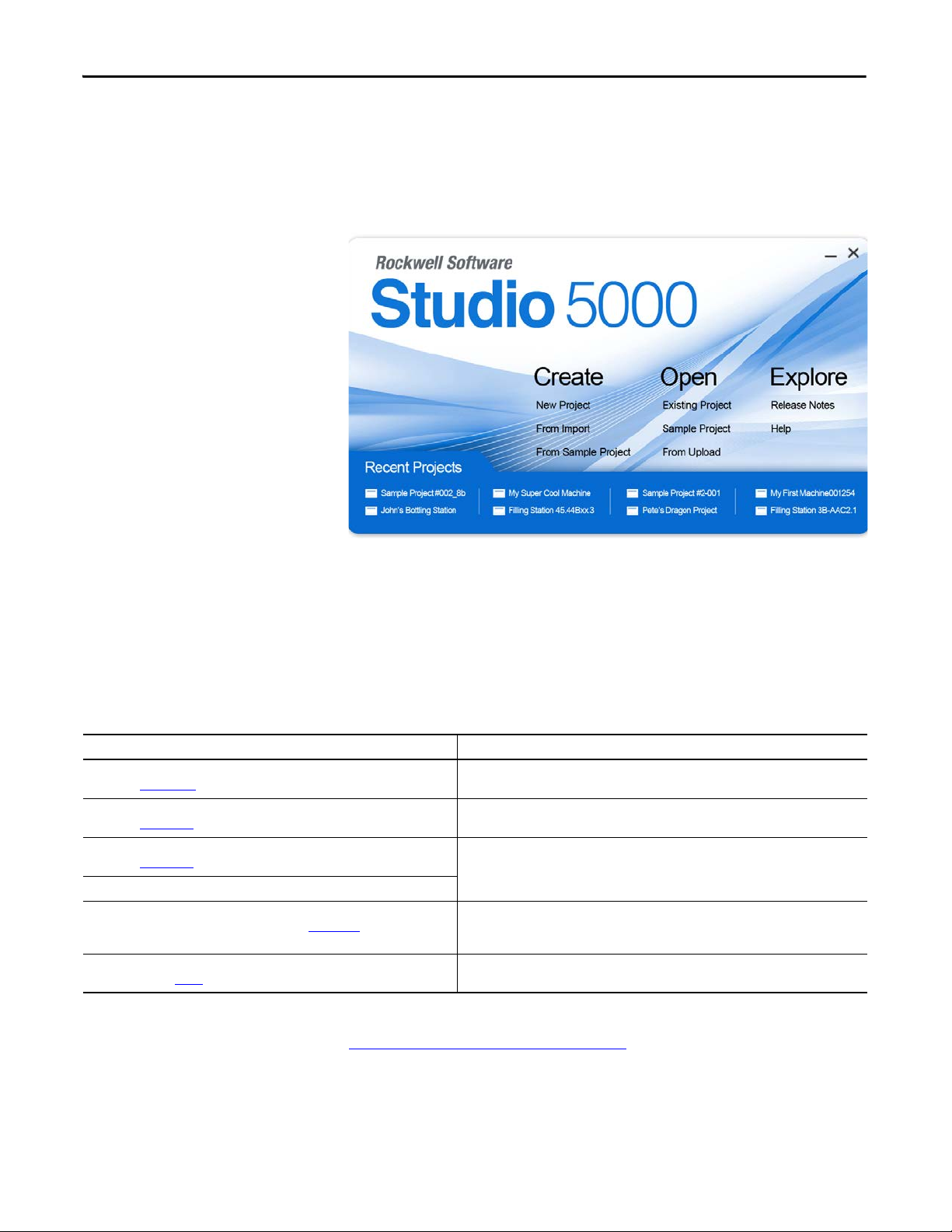
Studio 5000 Environment
The Studio 5000 Engineering and Design Environment combines engineering
and design elements into a common environment. The first element in the
Studio 5000 environment is the Logix Designer application. The Logix Designer
application is the rebranding of RSLogix 5000 software and will continue to be
the product to program Logix5000™ controllers for discrete, process, batch,
motion, safety, and drive-based solutions.
The Studio 5000 environment is the foundation for the future of Rockwell
Automation® engineering design tools and capabilities. It is the one place for
design engineers to develop all the elements of their control system.
Additional Resources
These documents contain additional information concerning related Rockwell
Automation products.
Resource Description
Kinetix 6200 and Kinetix 6500 Modular Multi-axis Servo Drive User Manual,
publication 2094-UM002
Kinetix Safe-off Feature Safety Reference Manual,
publication GMC-RM002
System Design for Control of Electrical Noise Reference Manual,
publication GMC-RM001
EMC Noise Management DVD, publication GMC-SP004
Kinetix Motion Control Selection Guide, publication GMC-SG001
Safety Guidelines for the Ap plication, Installation and Maintenance of Solid State
Control, publication
SGI-1.1
Provides information on installing, configuring, starting up, troubleshooting, and applications
for your Kinetix 6200 or Kinetix 6500 servo drive system.
Provides information on wiring and troubleshooting your Kinetix 5500 servo drives with the
safe-off feature.
Provides information, examples, and techniques designed to minimize system failures caused
by electrical noise.
Overview of Kinetix ser vo drives, motors, actuators, and motion accessories designed to help
make initial decisions for the motion control products best suited for your system
requirements.
Describes important differences between solid state control and hardwired electromechanical
devices.
You can view or download publications at
http://www.rockwellautomation.com/literature
documentation, contact your local Rockwell Automation distributor or sales
representative.
12 Rockwell Automation Publication 2094-RM001C-EN-P - May 2013
. To order paper copies of technical
Page 13

Chapter 1
Safety Concept
This chapter describes the safety performance level concept and how the
Kinetix 6200 and Kinetix 6500 drives can meet the requirements of Performance
Level e (PLe) and safety category 4 (CAT 4) per EN ISO 13849-1 and SIL CL3
per IEC EN 61508, EN 61800-5-2, and EN 62061.
Top ic Pag e
Safety Certification 13
Funct ional Proof Tests 16
PFD and PFH Definitions 17
Safe State 17
Safety Reaction Time 18
Considerations for Safety Ratings 18
Safety Certification
The TÜV Rheinland group has approved the Kinetix 6200 and Kinetix 6500
servo drives for use in safety-related applications up to ISO 13849-1 Performance
Level e (PLe) and category 4, SIL CL3 per IEC EN 61508, EN 61800-5-2 and
EN 62061 where removing the motion producing power is considered to be the
safe state. All of the examples related to I/O included in this manual are based on
achieving de-energization as the safe state for typical Machine Safety and
Emergency Shutdown (ESD) systems.
Rockwell Automation Publication 2094-RM001C-EN-P - May 2013 13
Page 14
Chapter 1 Safety Concept
IMPORTANT
Important Safety Considerations
The system user is responsible for the following:
• Validation of any sensors or actuators connected to the system
• Completing a system-level risk assessment
• Certification of the machine to the desired EN ISO 13849-1 performance
level or EN 62061 SIL level
• Project management and proof testing
• Programming the application software and the drive configurations in
accordance with the information in this manual
• Access control to the system, including password handling
• Analyzing all configuration settings and choosing the proper setting to
achieve the required safety rating
When applying functional safety, restrict access to qualified, authorized
personnel who are trained and experienced.
ATTENTION: When designing your system, consider how personnel exit the
machine if the door locks while they are in the machine. Additional
safeguarding devices can be required for your specific application.
Safety Category 4 Performance Definition
To achieve Safety Category 4 according to EN ISO 13849-1:2006, the safetyrelated parts have to be designed such that:
• the safety-related parts of machine control systems and/or their protective
equipment, as well as their components, shall be designed, constructed,
selected, assembled, and combined in accordance with relevant standards
so that they can withstand expected conditions.
• basic safety principles shall be applied.
• a single fault in any of its parts does not lead to a loss of safety function.
• a single fault is detected at or before the next demand of the safety
function, or, if this detection is not possible, then an accumulation of faults
shall not lead to a loss of the safety function.
• the average diagnostic coverage of the safety-related parts of the control
system shall be high, including the accumulation of faults.
• the mean time to dangerous failure of each of the redundant channels shall
be high.
• measures against common cause failure shall be applied.
14 Rockwell Automation Publication 2094-RM001C-EN-P - May 2013
Page 15

Safety Concept Chapter 1
IMPORTANT
TIP
Stop Category Definitions
The selection of a stop category for each stop function must be determined by a
risk assessment.
• Stop Category 0 is achieved with immediate removal of power to the
actuator, resulting in an uncontrolled coast to stop. Safe Torque Off
accomplishes a Stop Category 0 stop.
• Stop Category 1 is achieved with power available to the machine actuators
to achieve the stop. Power is removed from the actuators when the stop is
achieved.
• Stop Category 2 is a controlled stop with power available to the machine
actuators. The stop is followed by a holding position under power.
Refer to Safe Stop Mode
on page 55 for more information.
When designing the machine application, timing and distance must be
considered for a coast to stop (Stop Category 0 or Safe Torque Off). For more
information regarding stop categories, refer to EN 60204-1.
You can determine the drive/motor Stop Delay characteristics by using
Motion Analyzer software, version 4.7 or later.
Performance Level and Safety Integrity Level (SIL) CL3
For safety-related control systems, Performance Level (PL), according to EN ISO
13849-1, and SIL levels, according to EN 61508 and EN 62061, include a rating
of the system’s ability to perform its safety functions. All of the safety-related
components of the control system must be included in both a risk assessment and
the determination of the achieved levels.
Refer to the EN ISO 13849-1, EN 61508, and EN 62061 standards for complete
information on requirements for PL and SIL determination.
Refer to Chapter
and verification of a safety-related system containing the Kinetix 6200 and
Kinetix 6500 drives.
10 for more information on the requirements for configuration
Rockwell Automation Publication 2094-RM001C-EN-P - May 2013 15
Page 16

Chapter 1 Safety Concept
IMPORTANT
European Union Directives
If this product is installed within the European Union or EEC regions and has
the CE mark, the following regulations apply.
CE Conformity
Conformity with the Low Voltage Directive and Electromagnetic Compatibility
(EMC) Directive is demonstrated by using harmonized European Norm (EN)
standards published in the Official Journal of the European Communities. The
safe torque-off circuit complies with the EN standards when installed according
instructions found in this manual.
EMC Directive
This unit is tested to meet Council Directive 2004/108/EC Electromagnetic
Compatibility (EMC) by using these standards, in whole or in part:
• EN 61800-3 - Adjustable Speed Electrical Power Drive Systems,
Part 3 - EMC Product Standard including specific test methods
• EN 61326-2-1 EMC - Immunity requirements for safety-related systems
The product described in this manual is intended for use in an industrial
environment.
Functional Proof Tests
CE Declarations of Conformity are available online at
go to http://www.rockwellautomation.com/rockwellautomation/certification/
overview.page and in EC Declaration of Conformity on page 178.
Low Voltage Directive
These units are tested to meet Council Directive 2006/95/EC Low Voltage
Directive. The EN 60204-1 Safety of Machinery-Electrical Equipment of
Machines, Part 1-Specification for General Requirements standard applies in
whole or in part. Additionally, the standard EN 50178 Electronic Equipment for
use in Power Installations apply in whole or in part.
Refer to the Kinetix Servo Drives Specifications Technical Data, publication
GMC-TD003
The functional safety standards require that functional proof tests be performed
on the equipment used in the system. Proof tests are performed at user-defined
intervals and are dependent upon PFD and PFH values.
, for environmental and mechanical specifications.
Your specific application determines the time frame for the proof test
interval.
16 Rockwell Automation Publication 2094-RM001C-EN-P - May 2013
Page 17

Safety Concept Chapter 1
PFD and PFH Definitions
PFD and PFH Data
Safety-related systems can be classified as operating in either a Low Demand
mode, or in a High Demand/Continuous mode.
• Low Demand mode: where the frequency of demands for operation made
on a safety-related system is no greater than one per year or no greater than
twice the proof-test frequency.
• High Demand/Continuous mode: where the frequency of demands for
operation made on a safety-related system is greater than once per year or
greater than twice the proof test interval.
The SIL value for a low demand safety-related system is directly related to orderof-magnitude ranges of its average probability of failure to satisfactorily perform
its safety function on demand or, simply, average probability of failure on demand
(PFD). The SIL value for a High Demand/Continuous mode safety-related
system is directly related to the probability of a dangerous failure occurring per
hour (PFH).
These PFD and PFH calculations are based on the equations from IEC 61508
and show worst-case values.
This table provides test data for a 20-year proof test interval and demonstrates
the worst-case effect of various configuration changes on the data.
Safe State
Table 1 - PFD and PFH for 20-year Proof Test Interval
Attribute Single Encoder Dual Encoder
PFH [1e-9] 5.88 2.37
PFD [1e-4] 10.3 4.15
SFF % 99.4% 99.5%
The Safe State encompasses all operation that occurs outside of the other
monitoring and stopping behavior defined as part of the drive. In addition,
configuration takes place in the Safe State. While the drive is in the Safe State, all
safety control outputs, except the Door Control (DC_Out) output, are in their
safe state (de-energized). The Door Control (DC_Out) output is in either the
locked state or in the de-energized state depending upon the condition that
resulted in the safe state.
When you cycle power, the drive enters the Safe State for self-testing. If the selftests pass and there is a valid configuration, the drive remains in the Safe State
until a successful request for safe speed monitoring occurs.
If a Safe State fault is detected, the drive goes to the Safe State. This includes
faults related to integrity of hardware or firmware.
For more information on faults, refer to Chapter
Rockwell Automation Publication 2094-RM001C-EN-P - May 2013 17
12.
Page 18

Chapter 1 Safety Concept
IMPORTANT
Safety Reaction Time
Considerations for Safety Ratings
The safety reaction time is the amount of time from a safety-related event as
input to the system until the system is in the Safe State.
The safety reaction time from an input signal condition that triggers a safe stop,
to the initiation of the configured Stop Type, is 20 ms (maximum).
The safety reaction time from an overspeed event that triggers a safe stop, to the
actual initiation of the configured Stop Type, is equal to the value of the
[Overspeed Response Time] parameter.
For more information on overspeed response time, see Overspeed Response
Time on page 43.
The achievable safety rating of an application that uses safe speed monitoring is
dependent upon many factors, including the encoder setup, drive options, and
the type of motor.
When using two independent encoders to monitor motion and when installed in
a manner to avoid any common cause dangerous failure, the Kinetix 6200 and
Kinetix 6500 drives can be used in applications up to and including SIL CL3,
PLe, and CAT 4.
For applications that rely on commutation to generate torque and motion, a
safety rating up to and including SIL CL3, PLe, and CAT 4 can be achieved.
Some of the diagnostics performed on the encoder signals require motion to
detect faults. You must make sure that motion occurs at least once every six
months.
Considerations for Single-encoder Applications
When configured correctly, the Kinetix 6200 and Kinetix 6500 drive performs
these diagnostics on the encoder:
2
• Sin
• Detection of open or short-circuit
• Encoder supply voltage monitoring
• Detection of illegal quadrature transitions of the sine and cosine signals
+ Cos2 diagnostic
18 Rockwell Automation Publication 2094-RM001C-EN-P - May 2013
Page 19

Safety Concept Chapter 1
A safety rating up to and including SIL CL3, PLe, and CAT 4 can be achieved in
a single-encoder application with these requirements:
• The motor is a permanent magnet (PM) brushless AC motor.
• The motor controller must be configured as a closed-loop application with
field-oriented control by using the single-encoder for commutation.
• The motor-to-encoder coupling is designed to exclude shaft slippage as a
dangerous failure mechanism.
• The encoder is of the Sin/Cos type and is suitable for the desired safety
rating of the application.
An encoder that is suitable for SIL CL3 applications must follow one of
these two conventions:
– Use independent Sine/Cosine signals and be incapable of producing
simulated signals when under an error condition.
– Use simple or discreet circuitry with no complex or programmable
internal devices.
• Encoder voltage monitoring in Kinetix 6200 and Kinetix 6500 drives can
be enabled, depending on the feedback configuration.
• The system design of the motor/encoder-to-load coupling excludes shaft
slippage and breakage as a dangerous failure mechanism.
Understanding Commutation
Permanent magnet (PM), brushless AC motors are a class of synchronous motor
that depends on electronic brushless commutation for their operation. In PM
brushless motors, an electromagnetic field is created by the permanent magnets
on the rotor. A rotating magnetic field is created by a number of electromagnets
commutated electronically with IGBT’s at the right speed, order, and times.
Movement of the electromagnetic field is achieved by switching the currents in
the coils of the stator winding. This process is called commutation. Interaction of
the two electromagnetic fields produces magnetic force or torque.
Rockwell Automation Publication 2094-RM001C-EN-P - May 2013 19
Page 20

Chapter 1 Safety Concept
Notes:
20 Rockwell Automation Publication 2094-RM001C-EN-P - May 2013
Page 21

Chapter 2
About the Kinetix 6200 and Kinetix 6500
Safe Speed Monitoring Features
This chapter describes the safe speed monitoring features of the Kinetix 6200 and
Kinetix 6500 drives.
Top ic Pag e
Safety Functions 21
Hardware Features 24
Safety Functions
The Kinetix 6200 and Kinetix 6500 safe speed-monitoring servo drives feature
five inputs, two sets of safety outputs, and one bipolar safety output. Each of the
inputs and outputs support a specific safety function.
• Safe Stop (SS)
• Safe Limited Speed Monitoring (SLS)
• Door Monitoring (DM)
• Enabling Switch Monitoring (ESM)
• Lock Monitoring (LM)
• Door Control (DC)
An additional reset input provides for reset and monitoring of the safety circuit.
The drive can be used in single-axis or multi-axis applications, and can be
configured as a master or slave based on its location in the system.
Rockwell Automation Publication 2094-RM001C-EN-P - May 2013 21
Page 22
Chapter 2 About the Kinetix 6200 and Kinetix 6500 Safe Speed Monitoring Features
IMPORTANT
Operation Modes
You can configure the drive to operate in one of 11 user-selectable operation
modes, based on combinations of the safety functions listed on the previous page.
Operation Mode Page
Disabled – In this mode, all safety functions are disabled. 22
Safe Stop – The drive activates the configured Stop Category upon deactivation of the S afe Stop input or the
occurrence of a Stop Category fault.
Safe Stop with Door Monitoring – In addition to monitoring for Safe Stop, the drive monitors the status of
the door.
Safe Limited Speed – In addition to monitoring for Safe Stop, the drive monitors the feedback velocity and
compares it to a configurable Safe Speed Limit. If the velocity exceeds the limit, the drive initiates the
configured Stop Category.
Safe Limited Speed with Door Monitoring – In addition to monitoring for Safe Stop and Safe Limited Speed,
the drive monitors the status of the door.
Safe Limited Speed with Enabling Switch Control – In addition to monitoring for Safe Stop and Safe Limited
Speed, the drive monitors the status of the Enabling Switch input.
Safe Limited Speed with Door Monitor and Enabling Switch – In addition to monitoring for Safe Stop and
Safe Limited Speed, the drive monitors the status of the door and the Enabling Switch input.
Safe Limited Speed (status only) – In addition to monitoring for Safe Stop, the drive monitors the feedback
velocity and compares it to a configurable Safe Speed Limit. If the velocity exceeds the limit, the system
status is made available as a safe output intended for a safet y programmable logic controller. No stopping
action takes place.
Slave, Safe Stop – The drive performs the same functions as Safe Stop. However, it regards the Door Monitor
input as a Door Control output from an upstream axis, and performs a logical AND with its internal Door
Control signal to form the cascaded Door Control output.
Slave, Safe Limited Speed – The drive performs the same functions as Safe Limited Speed mode. However, it
regards the Door Monitor input as a Door Control output from an upstream axis, and performs a logical AND
with its internal Door Control signal to form the cascaded Door Control output.
Slave, Safe Limited Speed (status only) – The drive performs the same functions as Safe Limited Speed
Status Only mode. However, it regards the Door Monitor input as a Door Control output from an upstream
axis, and performs a logical AND with its internal Door Control signal to form the cascaded Door Control
output.
55
68
71
75
78
79
84
91
96
99
Disabled Mode
In Disabled mode, all safety functions are disabled. Input, output, or speed
monitoring diagnostics do not take place and all outputs are in their safe state.
Motion power is enabled for drive commissioning in this mode.
The drive monitors motion for Safe Stop in every mode except Disabled.
22 Rockwell Automation Publication 2094-RM001C-EN-P - May 2013
Page 23

About the Kinetix 6200 and Kinetix 6500 Safe Speed Monitoring Features Chapter 2
Lock Monitoring
Lock monitoring helps prevent access to the hazard during motion. In many
applications, it is not sufficient for the machine to initiate a stop command once
the door has been opened, because a high inertia machine can take a long time to
stop. Preventing access to the hazard until a safe speed has been detected can be
the safest condition. The lock monitoring feature is used to verify the operation
of the door locking mechanism.
Lock monitoring can be enabled on single units or on the first unit in a multi-axis
system. If the Lock Monitor input (LM_In) indicates that the door is unlocked
when the Door Control output (DC_Out) is in the locked state, or if the Lock
Monitor input indicates locked when the Door Monitor input (DM_In)
transitions from closed to open, the configured Stop Category is initiated.
Safe Maximum Speed, Safe Maximum Acceleration, and Safe Direction Monitoring
Three additional safety functions, Safe Maximum Speed (SMS), Safe Maximum
Acceleration (SMA) and Safe Direction Monitoring (SDM), operate
independent of the other modes, relying on the Safe Stop function. When you
configure the drive for Safe Maximum Speed, the feedback velocity is monitored
and compared against a user-configurable limit. If the measured velocity is greater
than or equal to the limit, the configured Stop Category is executed.
When Safe Acceleration Monitoring is enabled, the option monitors the
acceleration rate and compares it to a configured Safe Maximum Acceleration
Limit. If acceleration is detected as greater than or equal to the Safe Maximum
Acceleration Limit, an Acceleration fault occurs. If an Acceleration fault is
detected while the option is actively monitoring motion, the configured Stop
Category is initiated.
Safe Direction Monitoring is also activated via option configuration. The option
monitors the feedback direction and executes the configured Stop Category
when motion in the illegal direction is detected.
Refer to Chapter
9 for detailed information on these functions.
Rockwell Automation Publication 2094-RM001C-EN-P - May 2013 23
Page 24
Chapter 2 About the Kinetix 6200 and Kinetix 6500 Safe Speed Monitoring Features
IMPORTANT
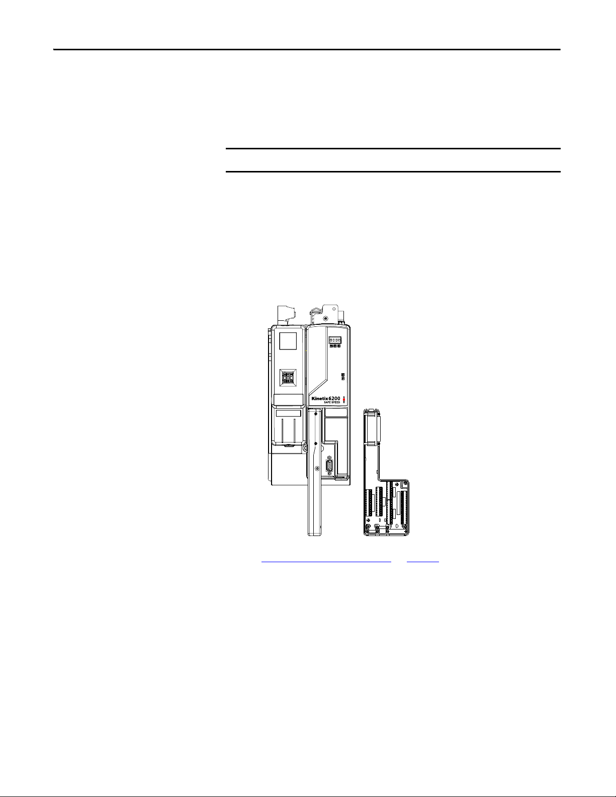
Kinetix 6200 and Kinetix 6500
IAM/AM Power Module
(IAM power module is shown)
Kinetix 6200 and Kinetix 6500 Control Module
(2094-SE02F-M00-S1 is shown)
2090-K6CK-D44M
Low-profile Connector Kit
Auxiliary Feedback, I/O, and Safety
Terminal Blocks
Hardware Features
The drive features five dual-channel inputs, two sets of sourcing safety outputs,
and one bipolar safety output. You can configure dual-channel inputs to accept a
following-contact configuration with two normally closed contacts, or one
normally closed and one normally open contact. They can also be configured for
single channel operation.
Single-channel operation does not meet SIL CL3, PLe, Cat 4 safety integrity.
These inputs also support output signal switching devices (OSSD). Each output
has integral pulse-test checking circuitry.
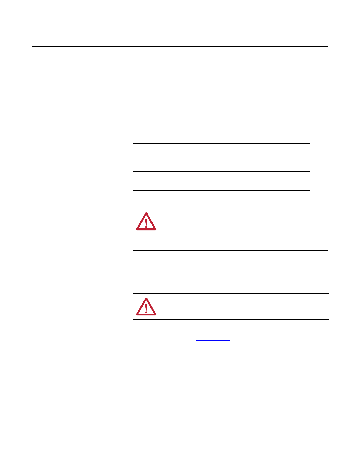
The 2090-K6CK-D44M (44-pin) low-profile connector kit is designed
specifically for use with the Kinetix 6200 and Kinetix 6500 modular drives.
Safety connections are made by using this connector kit.
Figure 1 - 44-pin Low-profile Connector Kit
INPUTS
AUX FEEDBACK
0 11 10 9 8 7 6 5 4 3 2 1
0 39 41 40 39 42 40 39 43 40 39 44 40
0 38 37 36 35 34 33 32 31 30 29 28 27 28 27 28 27 28 27
Refer to Wiring the Safety Connections on page 26 for the connector pinouts.
24 Rockwell Automation Publication 2094-RM001C-EN-P - May 2013
28 27 26 25 24 23 22 21 20 19 18 17 15 14 0
S0&S1 W/S0 DISABLED
S1 ONLY
S1 ONLY
Page 25
Chapter 3
Installation and Wiring
This chapter provides details on connecting devices and wiring the 2090-K6CKD44M Low-profile connector kit.
Top ic Pag e
General Safety Information 25
Power Supply Require ments 26
Wiring the Safety Connections 26
Terminal Connections 27
Compatible Encoders 28
General Safety Information
ATTENTION: The drive is intended to be part of the safety-related control
system of a machine. Before installation, a risk assessment must be performed
to determine whether the specifications of this safety option are suitable for all
foreseeable operational and environmental characteristics for the system being
installed.
Observe all electrical safety regulations stipulated by the appropriate technical
authorities.
ATTENTION: Make sure that the electrical power supplied to the drive is
switched off before making connections.
Refer to the Kinetix 6200 and Kinetix 6500 Modular Multi-axis Servo Drive
User Manual, publication 2094-UM002
, for more information.
Rockwell Automation Publication 2094-RM001C-EN-P - May 2013 25
Page 26
Chapter 3 Installation and Wiring
28 27 26 25 24 23 22 21 20 19 18 17 15 14 0
AUX FEEDBACK
0 11 10 9 8 7 6 5 4 3 2 1
0 39 41 40 39 42 40 39 43 40 39 44 40
INPUTS
0 38 37 36 35 34 33 32 31 30 29 28 27 28 27 28 27 28 27
S1 ONLY
S1 ONLY
S0&S1 W/S0 DISABLED
28 27 26 25 24 23 22 21 20 19 18 17 15 14 0
AUX FEEDBACK
0 11 10 9 8 7 6 5 4 3 2 1
0 39 41 40 39 42 40 39 43 40 39 44 40
INPUTS
0 38 37 36 35 34 33 32 31 30 29
28 27 28 27 28 27 28 27
S1 ONLY
S1 ONLY
S0&S1 W/S0 DISABLED
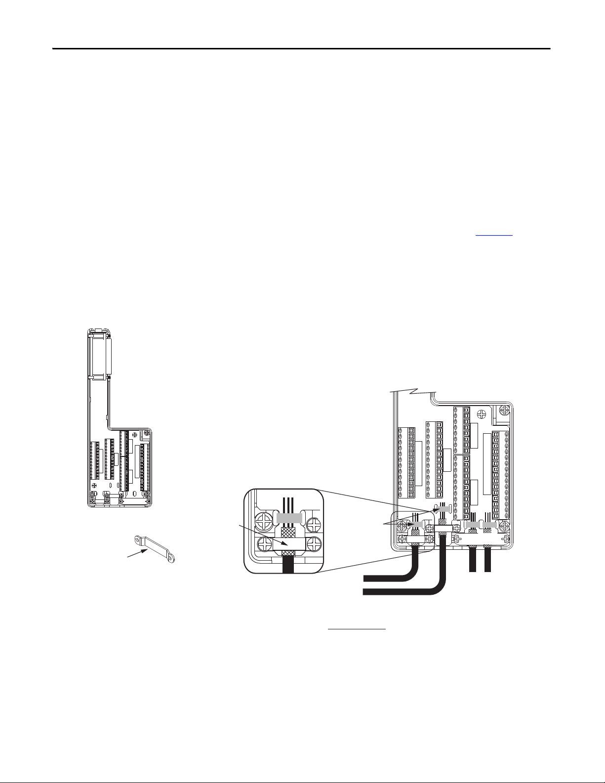
Clamp
2090-K6CK-D44M
Low-profile Connector Kit
Use tie wraps (4x)
for stress relief.
Turn clamps over for smaller
diameter cables.
Aux Feedback and I/O
Wires and Cables
Safety Wires
and Cables
Use shield clamps (3x) for
high-frequency bonding.
Kit pin numbering corresponds to the IOD
connector. Pins 27, 28, 39, and 40 are
given multiple terminals to
accommodate additional connections.
Power Supply Requirements
Wiring the Safety Connections
The external power supply must conform to the Directive 2006/95/EC Low
Voltage, by applying the requirements of EN61131-2 Programmable Controllers,
Part 2 - Equipment Requirements and Tests and one of the following:
• EN60950 - SELV (Safety Extra Low Voltage)
• EN60204 - PELV (Protective Extra Low Voltage)
• IEC 60536 Safety Class III (SELV or PELV)
• UL 508 Limited Voltage Circuit
• 21.6…28.8V DC must be supplied by a power supply that complies with
IEC/EN60204 and IEC/EN 61558-1.
For planning information, refer to the guidelines in Industrial Automation
Wiring and Grounding Guidelines, Allen-Bradley publication 1770-4.1
.
Safety connections are made by using the 2090-K6CK-D44M low-profile
connector kit.
Figure 2 - Making Safety Connections
Refer to the Kinetix 6200 and Kinetix 6500 Modular Multi-axis Servo Drive
User Manual, publication 2094-UM002
signal descriptions and wiring examples when using the 2090-K6CK-D44M
connector kit.
26 Rockwell Automation Publication 2094-RM001C-EN-P - May 2013
, for safety, auxiliary feedback, and I/O
Page 27

Installation and Wiring Chapter 3
Terminal Connections
Prepare wires for termination on the IOD connector with a 5 mm (0.2 in.) strip
length. Tighten all terminal screws firmly and recheck them after all connections
have been made. Recommended terminal screw torque is 0.4 N•m (3.5 lb•in).
Refer to page 143
Table 2 - IOD Connector Pinouts
(1)
IOD Pin
0 Chassis Ground Shield
1
2
3
4
5
6
7 Clock Output + AUX_CLK+ 29 (68) Safe Limited Speed Output 0 SLS_OUT_CH0
8 Clock Output - AUX_CLK- 30 (78) Safe Limited Speed Output 1 SLS_OUT_CH1
9 Encoder 5V Power Output EPWR_5V 31 (S32) Door Monitor Input 0 DM_IN_CH0
10 Encoder Common ECOM 32 (S42) Door Monitor Input 1 DM_IN_CH1
11 Encoder 9V Power Output EPWR_9V 33 (X32) Lock Monitor Input 0 LM_IN_CH0
12 Reserved – 34 (X42) Lock Monitor Input 1 LM_IN_CH1
13 Reserved – 35 (51) Door Control Channel Output- DC_OUT_CH0
14 24V Power Out 24VPWR
15 24V Common 24VCOM 37 (S72) Enabling Sw. Mon. Input 0 ESM_IN_CH0
16 Reserved – 38 (S82) Enabling Sw. Mon. Input 1 ESM_IN_CH1
17 (A1) Safety 24V Power Input SPWR 39 24V Power Out 24VPWR
18 (A2) Safety 24V Common SCOM 40 24V Common 24VCOM
19 (S12) Safe Stop Input 0 SS_IN_CH0 41 Digital Input 1 INPUT1
20 (S22) Safe Stop Input 1 SS_IN_CH1 42 Digital Input 2 INPUT2
21 (34) Safe Stop Output 0 SS_OUT_CH0 43 Digital Input 3 INPUT3
22 (44) Safe Stop Output 1 SS_OUT_CH1 44 Digital Input 4 INPUT4
Description Signal IOD Pin
Sine Differential Input +
A Differential Input +
Sine Differential Input A Differential Input -
Cosine Differential Input +
B Differential Input +
Cosine Differential Input B Differential Input -
Data Differential Input +
Index Differential Input +
Data Differential Input Index Differential Input -
AUX_S IN+
AUX_A +
AUX_S INAUX_A -
AUX_CO S+
AUX_B +
AUX_CO SAUX_B -
AUX_DATA+
AUX_I +
AUX_DATAAUX_I -
(2)
for the I/O signal electrical specifications.
(1)
Description Signal
23 (S52) Safe Limited Speed Input 0 SLS_IN_CH0
24 (S62) Safe Limited Speed Input 1 SLS_IN_CH1
25 Reset Reference RESET_REF
26 (S34) Reset Input RESET_IN
27 (S11) Pulse Test Output 0 TEST_OUT_0
28 (S21) Pulse Test Output 1 TEST_OUT_1
36 (52) Door Control Channel Output+ DC_OUT_CH1
(3)
(1) Designators in parenthe sis refer to the Guardmaster® MSR57P safety relay and PowerFlex® 750-Series safety option terminals.
(2) Signals 24VPWR and 24VCOM (IOD-14 and IOD-15) do not apply to 2094-xx02x-M0x-S1 control modules.
(3) Use signals 24VPWR and 24VCOM (IOD-39 and IOD-40) as a 24V DC source to operate the digital inputs (50 mA maximum per input).
Rockwell Automation Publication 2094-RM001C-EN-P - May 2013 27
Page 28

Chapter 3 Installation and Wiring
Compatible Encoders
Cat. No. and Description Additional Resources
Sin/Cos Encoders
Incremental Encoders
Rotary Motors
(1) Maximum cable length for sin/cos encoder s is 90 m (295 ft).
(2) Maximum cable length for incremental encoders is 30.5 m (100 ft) when using 5V.
(1)
842HR-xJxxx15FWYx
845T-xx12xxx-x and 845T-xx13xxx-x
845T-xx42xxx and 845T-xx43xxx-x
(2)
845T-xx52xxx and 845T-xx53xxx-x
845H-SJxxx4xxYxx
1326AB-Bxxxx-M2L/S2L
MP-Series™ motors with embedded Sin/Cos or incremental encoders
Any motor with SRS-60 Stegmann encoder
Any motor with SRM -60 Stegmann encoder
These feedback devices are supported.
Refer to the Bulletin 842HR Sin/Cosine Encoders product profile, publication
842HR-PP001, for more information on these encoders.
Refer to the Sensors Reference Catalog, publication C116
number, dimensions, and specifications for Bulletin 845T and 845H
Incremental Encoders.
Refer to the Kinetix Motion Control Select ion Guide, publication GMC-SG001
for more information on these motors.
Refer to the produ ct documentation for your s pecific motor to determine t he
encoder type.
, for catalog
,
28 Rockwell Automation Publication 2094-RM001C-EN-P - May 2013
Page 29

Chapter 4
IMPORTANT
Speed Monitoring I/O Signals
This chapter describes the safe-speed monitoring input and output signals of the
Kinetix 6200 and Kinetix 6500 drives.
Top ic Pag e
Inputs 29
Outputs 35
Inputs
The Kinetix 6200 and Kinetix 6500 drives have five inputs capable of safetycertified dual-channel support. Each dual-channel input supports a specific safety
function of the drive: Safe Stop, Safe Limited Speed, Door Monitoring, Enabling
Switch Monitoring, and Lock Monitoring.
All five inputs are electrically identical and rely on the same pair of pulse test
outputs, Test_Out_0 and Test_Out_1, when not using the OSSD configuration.
The inputs can be configured for one of the following settings:
• Not used
• Dual-channel equivalent
• Dual-channel equivalent 3 s
• Dual-channel complementary
• Dual-channel complementary 3 s
• Dual-channel SS equivalent 3 s
• Single channel
Single-channel configuration is not SIL CL3, PLe, Cat 4.
When configured for dual-channel operation, the consistency between the two
channels is evaluated. For dual-channel equivalent configurations, the active state
for both channel 0 and channel 1 is ON. For dual-channel complementary
configurations, the active state for channel 0 is ON and the active state for
channel 1 is OFF. Any time both channels are not active, the input pair is
evaluated as OFF.
Rockwell Automation Publication 2094-RM001C-EN-P - May 2013 29
Page 30
Chapter 4 Speed Monitoring I/O Signals
Channel 0
Active
Inactive
Channel 1
Active
Inactive
Evaluated Status
ON
OFF
Cycle Inputs Required
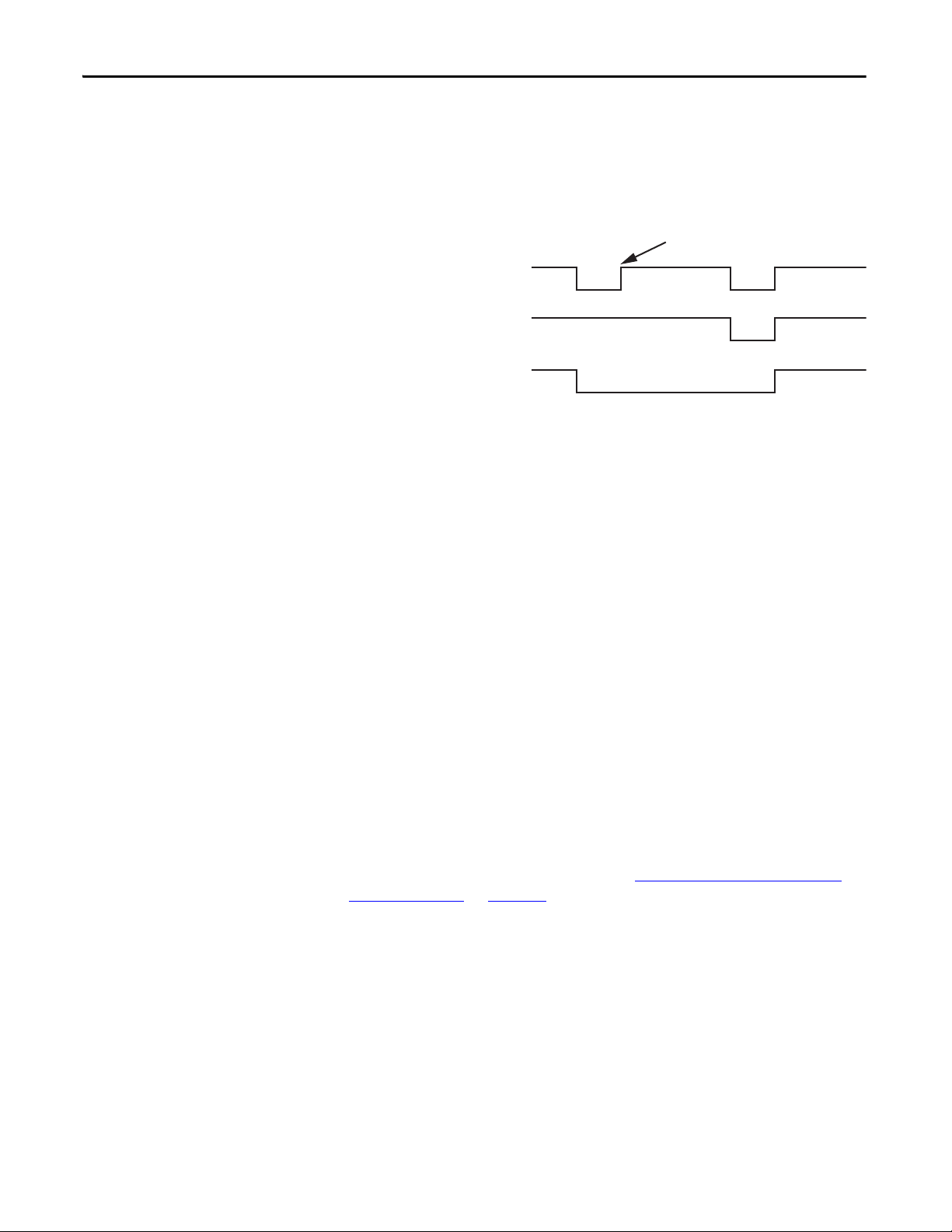
When both channels are active, if one channel’s input terminal transitions from
active to inactive and back to active, while the other channel’s input terminal
remains active, both channels must go inactive at the same time before the
evaluated status can return to ON. This condition is called ‘cycle inputs required’.
Figure 3 - Cycle Inputs Required
If inputs are configured with the following dual channel settings, an Input fault
occurs if the inputs are discrepant for longer than 3 seconds or if a ‘cycle inputs
required’ condition exists lor longer than 3 seconds.
• Dual-channel equivalent 3 s
• Dual-channel complementary 3 s
• Dual-channel SS equivalent 3 s
If inputs are configured with one of the following dual channel settings, which
have no limit on the length of time that inputs can be discrepant, an Input fault
does not occur for any discrepant condition or for any ‘cycle inputs required’
condition.
• Dual-channel equivalent
• Dual-channel complementary
For all input settings except Dual-channel SS equivalent 3 s, if one or two
channels are connected to a 24V DC source other than terminals IOD-27 and
IOD-28, a fault occurs.
I/O faults are Stop Category faults that initiate the configured Stop Category.
I/O faults are latched until the drive is successfully reset.
For more information on I/O faults, refer to Troubleshooting the
Safe Speed
Monitoring Drive on page 133.
30 Rockwell Automation Publication 2094-RM001C-EN-P - May 2013
Page 31

Speed Monitoring I/O Signals Chapter 4
Test_Out_0 (IOD-27)
Test_Out_1 (IOD-28)
Dual-channel
Equivalent
Safety Device
Dual-channel
Complementary
Safety Device
Single
Channel
Safety Device
Solid State
Safety Device
Drive
N/C
N/C
Input 1
Input 0
GND
OSSD2
OSSD1
Drive
Drive
Drive
Input 1
Input 0
Input 1
Input 0
24V_COM (IOD-18)
Input 1
Input 0
Test_Out_0 (IOD-27)
Test_Out_1 (IOD-28)
Test_Out_0 (IOD-27)
Test_Out_1 (IOD-28)
Test_Out_0 (IOD-27)
Test_Out_1 (IOD-28)
IMPORTANT
When using a dual-channel complementary device, the normally-open input
must be connected to the second input, as shown in the illustration. For example,
if the door is open when the input is ON, the normally-open contact must be the
second input (Input 1).
Figure 4 - Safety Input Wiring Examples
Cross wiring of Test Outputs to Inputs is not allowed. For example, do not
connect TEST_OUT_0 to Input 1 or TEST_OUT_1 to Input 0.
Table 3 - IOD Connector Input Terminals
Function
Input 0 = Channel 0 IOD-19 IOD-23 IOD-31 IOD-37 IOD-33
Input 1 = Channel 1 IOD-20 IOD-24 IOD-32 IOD-38 IOD-34
Safe Stop
(SS_In)
Safe Limited
Speed
(SLS_In)
Door Monitoring
(DM_In)
Enabling Switch
Monitoring
(ESM_In)
Lock
Monitoring
(LM_In)
Short-circuits of the input loop to ground or 24V are detected. For dual-channel
inputs, cross loops are also detected.
Rockwell Automation Publication 2094-RM001C-EN-P - May 2013 31
Page 32

Chapter 4 Speed Monitoring I/O Signals
Safe Stop Input (SS_In)
The SS_In input is intended for connection to an E-Stop device.
The SS_In input must be active to initiate Safe Stop monitoring. If the SS_In
input is being monitored, a transition from ON to OFF (closed to open) is used
to request the configured Stop Category.
In a cascaded configuration, the SS_In inputs of the middle and last drives are
connected to the Safe Stop (SS_Out) output of an upstream drive.
Safe Limited Speed Input (SLS_In)
The SLS_In input is used to connect to a switch whose OFF state requests Safe
Limited Speed monitoring.
If Safe Limited Speed monitoring is configured, the SLS_In input is monitored
from the time of a successful Safe Stop Reset or Safe Limited Speed Reset, until
the time that the configured Stop Category is initiated or the Safe State is
entered.
If the SLS_In input is being monitored, the OFF state is used to request the Safe
Limited Speed monitoring functionality of the drive.
In a cascaded configuration, the SLS_In inputs of the middle and last drives are
connected to the Safe Limited Speed (SLS_Out) output of an upstream drive.
Door Monitor Input (DM_In)
This input monitors the status of the door to indicate if it is open or closed. The
DM_In input can be connected to a non-guardlocking switch if the door does
not need to be locked. The door status is monitored by the first unit in multi-axis
systems.
The DM_In input is intended for connection to a guardlocking switch when the
drive is configured as a master device with door monitoring. When the drive is
configured as a slave in a cascaded system, its DM_In input is connected to the
Door Control output (DC_Out) of the upstream drive.
Refer to Door Control Output (DC_Out)
on page 38 for more information.
32 Rockwell Automation Publication 2094-RM001C-EN-P - May 2013
Page 33

Speed Monitoring I/O Signals Chapter 4
Enabling Switch Monitor Input (ESM_In)
The ESM_In input is intended to be connected to an enabling switch. The drive
uses the ESM_In input only as a safety enable, not for control. The ESM_In
inputs function and monitoring is performed by the first unit in multi-axis
systems.
The ESM_In input ON state is used to enable motion under mode-specific
conditions in the Safety Limited Speed with Enabling Switch and Safe Limited
Speed with Door Monitoring and Enabling Switch Monitoring modes.
Refer to Safe Limited Speed with Door Monitoring Mode
Limited Speed with Enabling Switch Monitoring Mode on page 78 for the
conditions that must be true to start monitoring the ESM_In input.
If the ESM_In input is OFF while it is being monitored, an ESM Monitoring
fault occurs and the drive initiates the configured Stop Category.
Refer to Chapter
12 for information on faults and how to recover from them.
on page 75 and Safe
Lock Monitor Input (LM_In)
The LM_In input verifies that the guardlocking solenoid switch is locked. It is
intended to confirm the door control function.
The LM_In input is monitored by the first unit in multi-axis systems.
Rockwell Automation Publication 2094-RM001C-EN-P - May 2013 33
Page 34

Chapter 4 Speed Monitoring I/O Signals
Manual
Manual
Monitored
Reset
Reset
RESET_IN
RESET_IN
IOD-25
IOD-26
IOD-25
IOD-26
IMPORTANT
Reset Input (Reset_In)
The Reset input is for reset and monitoring of the safety circuit. The reset input
can be configured for automatic, manual, or manual monitored reset types.
Wire the reset input terminal (IOD-26) to the 24V DC input terminal,
(IOD-25), depending on the configured reset type, as shown.
Figure 5 - Reset Input Configurations
If you configure the drive for automatic reset, wiring of the reset input
terminal (IOD-26) is not required.
34 Rockwell Automation Publication 2094-RM001C-EN-P - May 2013
Page 35

Speed Monitoring I/O Signals Chapter 4
Drive (Master)
SS_OUT_CH0
SS_OUT_CH1
Drive (Slave)
SS_IN_CH0
SS_IN_CH1
IOD-19 and IOD-20 are configured
as 2 OSSD 3s inputs.
IOD-21
IOD-19
IOD-22
IOD-20
Outputs
The drive has three safety control outputs. The outputs have various output
current capabilities, depending on function.
See the specifications in Appendix
A to verify your power requirements.
Safe Stop Output (SS_Out)
The safe state for this signal is OFF.
These outputs are typically used in multi-axis applications. In multi-axis
applications, you can use these outputs to daisy-chain the master drive to a slave.
For SS_Out to SS_In cascaded signals, the interface is a dual-channel sourcing
solid-state safety output connected to a dual-channel safety input configured as
OSSD. The outputs are pulse-tested.
Figure 6 - SS_Out to SS_In Connections for Multi-axis Applications
For more information on multi-axis configurations, see Cascaded Configurations
starting on page 89
Rockwell Automation Publication 2094-RM001C-EN-P - May 2013 35
.
Page 36

Chapter 4 Speed Monitoring I/O Signals
Alternately, the first SS_Out output can be used to signal a programmable logic
controller (PLC) that a Safe Stop has been requested.
If the SS_In is ON (closed) and a successful Safe Stop Reset is performed, the
SS_Out output is turned ON. If Lock Monitoring is not enabled or the door
control logic state is Unlock, the SS_Out signal turns ON immediately when the
SS_In turns ON. If Lock Monitoring is enabled, and the door control logic state
is Lock, the SS_Out signal is not turned ON until the door has been locked by
using the DC_Out signal and the LM_In input has been verified as ON.
If the Stop Category is initiated or if a Safe Stop is initiated due to a fault, the
SS_Out output is turned OFF.
If an error is detected on either channel of the dual-channel output, a fault occurs.
I/O faults are Stop Category faults that initiate the configured Stop Category.
The fault is latched until the drive is successfully reset.
For more information on faults, refer to Chapter
12.
Safe Limited Speed Output (SLS_Out)
The safe state for this signal in all cases is OFF.
The SLS_Out output functionality is determined by the configured Operation
mode. If the SLS_In is ON and a successful Safe Stop or Safe Limited Speed reset
is performed, the SLS_Out turns ON in all Safe Limited Speed modes except
Safe Limited Speed Status Only.
For the Safe Limited Speed modes (SLS), the SLS_Out is used to interconnect
speed monitoring drives in multi-axis applications. For SLS_Out to SLS_In
cascaded signals, the interface is a dual-channel sourcing solid state safety output
connected to a dual-channel safety input configured as OSSD.
36 Rockwell Automation Publication 2094-RM001C-EN-P - May 2013
Page 37

Speed Monitoring I/O Signals Chapter 4
Drive (Master)
SLS_OUT_CH0
SLS_OUT_CH1
Drive (Slave)
SLS_IN_CH0
SLS_IN_CH1
IOD-29
IOD-30
IOD-24
IOD-23
For a single unit system or the last unit in a cascaded system, the SLS_Out is
intended to be connected to an input of a safety programmable logic controller
(PLC). The same PLC could also control the Safe Stop function with a safe PLC
output connected to the Safe Stop input (SS_In).
For the first or middle units in a cascaded system, the SLS_Out is intended to be
connected to the Safe Limited Speed input (SLS_In) of the next drive in the
cascaded system. This lets one SLS switch enable Safe Limited Speed on all axes
at the same time.
Figure 7 - SLS_Out to SLS_In Connections for Multi-axis Applications
For more information on multi-axis configurations, see Cascaded Configurations
starting on page 89
.
For Safe Limited Speed Status Only modes, the SLS_Out output is used as an
indication that the Safe Limited Speed monitoring is active and the monitored
speed is less than the configured Safe Speed Limit. If the speed is greater than or
equal to the Safe Speed Limit, the SLS_Out is turned OFF. When Safe Limited
Speed monitoring is not active or the drive is in a SLS Monitoring Delay, the
SLS_Out output is OFF. The SLS_Out output is turned OFF when a Safe Stop
has been initiated, a fault has occurred, or the drive is in the safe state.
See Safe Limited Speed Status Only Mode
on page 84 for more information.
If an error is detected on either channel of the dual-channel output, a fault occurs.
I/O faults are Stop Category faults that initiate the configured Stop Category.
The fault is latched until the drive is successfully reset.
For more information on faults, refer to Chapter
12.
Rockwell Automation Publication 2094-RM001C-EN-P - May 2013 37
Page 38

Chapter 4 Speed Monitoring I/O Signals
TEST_OUT_CH0
DM_IN_CH0
DM_IN_CH1
LM_IN_CH0
LM_IN_CH1
DC_OUT_CH1
DC_OUT_CH0
Door Status Locking Mechanism Status
TEST_OUT_CH1 TEST_OUT_CH0 TEST_OUT_CH1
IOD-27 IOD-28
IOD-27
IOD-28
IOD-31
IOD-32
IOD-33
IOD-34
IOD-36
IOD-35
TIP
Door Control Output (DC_Out)
You can use this output for door control in single-axis and multi-axis systems.
This output attempts to maintain last state when a fault occurs.
The DC_Out output is updated based on door control logic status, the [Door
Control Output] parameter setting, and any Safe State faults that can be
detected.
This output is Unlocked only when motion is verified to be at Standstill Speed or
Safe Limited Speed.
Figure 8 - Door Control and Lock Monitoring
Check your interlock switch for internal jumpers before installation.
If an error is detected on either channel of the dual-channel output, a fault occurs.
I/O faults are Stop Category faults that initiate the configured Stop Category.
The fault is latched until the drive is successfully reset.
For more information on faults, refer to Chapter
The DC_Out output can be used as a bipolar output in Power to Release or
Power to Lock configurations, or it can be configured as Cascading (2Ch
Sourcing).
12.
38 Rockwell Automation Publication 2094-RM001C-EN-P - May 2013
Page 39

Speed Monitoring I/O Signals Chapter 4
DM_IN_CH0 DM_IN_CH1
DC_OUT_CH0
DC_OUT_CH1
Drive (Master)
Drive (Slave)
IOD-36
IOD-35
IOD-31
IOD-32
+
-
+
-
+
+
-
No
Load
Bi-polar
Load
Single-ended
Load
Door Status 2-Channel
Source
(1)
+24V DC
Door Control
Sourcing Output
Door Control
Sinking Output
+24V DC Common
Load
Load
Input Circuit
Input Circuit
IOD-35
IOD-35
IOD-36
IOD-36
IOD-35
IOD-35
IOD-36
IOD-36
(2)
When the Door Control output is configured as cascading (2Ch Sourcing), the
dual-channel bipolar output acts as two sourcing outputs capable of driving the
OSSD Door Monitor input (DM_In) of the next speed monitoring drive in the
cascaded chain. The DC_out output can also be used as a source for general
purpose inputs. In this configuration, the current is limited to 20 mA.
Figure 9 - Door Control Cascading Outputs
Only the wiring configurations shown below are supported for the Door Control
output.
Figure 10 - Door Control Output Wiring
(1) When wired as a source for a safety input, current is limited to 20 mA per output.
(2) For example, SmartGuard 600 controller, Guard I/O module.
Short-circuits of the output loop to ground or 24V are detected. For cascaded
outputs, cross loops are also detected.
Rockwell Automation Publication 2094-RM001C-EN-P - May 2013 39
Page 40

Chapter 4 Speed Monitoring I/O Signals
Notes:
40 Rockwell Automation Publication 2094-RM001C-EN-P - May 2013
Page 41

Chapter 5
General Device and Feedback Monitoring
Configuration
This chapter describes the general and feedback configuration settings that must
be configured to operate the safe speed monitoring features.
Top ic Pag e
Cascaded Configuration 41
Operation Mode 42
Reset Type 42
Overspeed Response Time 43
General Parameter List 48
Feedback Monitoring 49
Feedback Parameter List 54
Cascaded Configuration
The drive can be used in single-axis or multi-axis applications. The [System
Configuration] parameter indicates the drive’s location in the system: Single Unit
(Single), Cascaded First Unit (Multi First), Cascaded Middle Unit (Multi Mid),
or Cascaded Last Unit (Multi Last). Single unit and cascaded first options are
system masters.
Refer to Chapter
8 for more information on cascaded configurations.
Rockwell Automation Publication 2094-RM001C-EN-P - May 2013 41
Page 42

Chapter 5 General Device and Feedback Monitoring Configuration
TIP
Operation Mode
Reset Type
You can configure the drive to operate in one of 11 user-selectable Operation
modes, based on combinations of the safety functions the drive supports. The
modes, except for Disabled, are described in detail in subsequent chapters of this
manual.
Table 4 - Safety Function Combinations
For these modes See
Master, Safe Stop Chapter
Master, Safe Stop - Door Monitor
Master, Safe Stop - Safe Limited Speed Chapter 7
Master, Safe Stop - Safe Limited Speed - Door Monitor
Master, Safe Stop - Safe Limited Speed - Enable Switch
Master, Safe Stop - Safe Limited Speed - Door Monitor - Enable Switch
Master, Safe Stop - Safe Limited Speed Status Only
Slave, Safe Stop Chapter
Slave, Safe Limited Speed
Slave, Safe Limited Speed Status Only
6
8
You can configure the [Reset Type] parameter as automatic, manual, or manual
monitored. The default is manual monitored. The configured Reset Type applies
to both Safe Stop and Safe Limited Speed Resets.
The Reset input does not require wiring for automatic reset configurations.
See Safe Stop Reset
page 73
, page 76, and page 78 for details on how the [Reset Type] parameter
on page 63 and page 69, and Safe Limited Speed Reset on
affects Safe Stop and Safe Limited Speed operation.
ATTENTION: For all types of reset (automatic, manual, or manual monitored),
if a reset of the Safe Stop or Safe Limited Speed functions can result in machine
operation, the other speed monitoring functions must be configured to detect
and prevent dangerous motion.
ATTENTION: The Safe Stop Reset does not provide safety-related restart
according to EN 60204-1. Restart must be performed by external measures if
automatic restart could result in a hazardous situation. You are responsible for
determining whether automatic restart could pose a hazard.
42 Rockwell Automation Publication 2094-RM001C-EN-P - May 2013
Page 43

General Device and Feedback Monitoring Configuration Chapter 5
Overspeed Response Time
The [Overspeed Response Time] parameter setting determines the maximum
reaction time from an overspeed event to the initiation of the configured [Stop
Category]. The safety reaction time from an overspeed event that triggers a Stop
Category, to the actual initiation of that Stop Category, is equal to the value of
the [Overspeed Response Time] parameter. The configurable options are 42, 48,
60, 84, 132, 228, and 420 ms.
The [Overspeed Response Time] parameter setting also determines the speed
resolution that can be achieved. The Overspeed Response Time and the encoder
resolution affect the speed resolution accuracy as shown in the tables on the
following pages.
Speed Resolution Accuracy for Rotary Systems
Table 5 - En coder Res olution 16 lines/rev
Overspeed Response Time
Setting
42 156.253 156.283 156.583 159.583 189.583 489.583
48 78.127 78.142 78.292 79.792 94.792 244.792
60 39.063 39.071 39.146 39.896 47.396 122.396
84 19.532 19.535 19.573 19.948 23.698 61.198
132 9.766 9.768 9.786 9.974 11.849 30.599
228 4.883 4.884 4.893 4.987 5.924 15.299
420 2.441 2.442 2.447 2.493 2.962 7.650
1 10 100 1000 10,000 100,000
Speed (RPM)
Table 6 - Encoder Resolution 128 lines/rev
Overspeed Response Time
Setting
42 19.535 19.565 19.865 22.865 52.865 332.031
48 9.767 9.782 9.932 11.432 26.432 166.016
60 4.884 4.891 4.966 5.716 13.216 83.008
84 2.442 2.446 2.483 2.858 6.608 41.504
132 1.221 1.223 1.242 1.429 3.304 20.752
228 0.610 0.611 0.621 0.715 1.652 10.376
420 0.305 0.306 0.310 0.357 0.826 5.188
1 10 100 1000 10,000 93,750
Speed (RPM)
Rockwell Automation Publication 2094-RM001C-EN-P - May 2013 43
Page 44

Chapter 5 General Device and Feedback Monitoring Configuration
Table 7 - Encoder Resolution 1000 lines/rev
Overspeed Response Time
Setting
42 2.503 2.533 2.833 5.833 35.833 42.500
48 1.252 1.267 1.417 2.917 17.917 21.250
60 0.626 0.633 0.708 1.458 8.958 10.625
84 0.313 0.317 0.354 0.729 4.479 5.313
132 0.156 0.158 0.177 0.365 2.240 2.656
228 0.078 0.079 0.089 0.182 1.120 1.328
420 0.039 0.040 0.044 0.091 0.560 0.664
1 10 100 1000 10,000 12,000
Speed (RPM)
Table 8 - Encoder Resolution 1024 lines/rev
Overspeed Response Time
Setting
42 2.445 2.475 2.775 5.775 35.775 41.504
48 1.222 1.237 1.387 2.887 17.887 20.752
60 0.611 0.619 0.694 1.444 8.944 10.376
84 0.306 0.309 0.347 0.722 4.472 5.188
132 0.153 0.155 0.173 0.361 2.236 2.594
228 0.076 0.077 0.087 0.180 1.118 1.297
420 0.038 0.039 0.043 0.090 0.559 0.648
1 10 100 1000 10,000 11,718.75
Speed (RPM)
Table 9 - Encoder Resolution 3000 lines/rev
Overspeed Response Time
Setting
42 0.837 0.867 1.167 4.167 14.167
48 0.418 0.433 0.583 2.083 7.083
60 0.209 0.217 0.292 1.042 3.542
84 0.105 0.108 0.146 0.521 1.771
132 0.052 0.054 0.073 0.260 0.885
228 0.026 0.027 0.036 0.130 0.443
420 0.013 0.014 0.018 0.065 0.221
1 10 100 1000 4000
Speed (RPM)
44 Rockwell Automation Publication 2094-RM001C-EN-P - May 2013
Page 45

General Device and Feedback Monitoring Configuration Chapter 5
Table 10 - Encoder Resolution 5000 lines/rev
Overspeed Response Time
Setting
42 0.503 0.533 0.833 3.833 8.500
48 0.252 0.267 0.417 1.917 4.250
60 0.126 0.133 0.208 0.958 2.125
84 0.063 0.067 0.104 0.479 1.063
132 0.031 0.033 0.052 0.240 0.531
228 0.016 0.017 0.026 0.120 0.266
420 0.008 0.008 0.013 0.060 0.133
1 10 100 1000 2400
Speed (RPM)
Speed Resolution Accuracy for Linear Systems
Table 11 - Encoder Resolution 500 lines/mm
Overspeed Response Time
Setting
42 0.083 0.084 0.087 0.117 0.417 1.417
48 0.042 0.042 0.043 0.058 0.208 0.708
60 0.021 0.021 0.022 0.029 0.104 0.354
84 0.010 0.010 0.011 0.015 0.052 0.177
132 0.005 0.005 0.005 0.007 0.026 0.089
228 0.003 0.003 0.003 0.004 0.013 0.044
420 0.001 0.001 0.001 0.002 0.007 0.022
0.01 0.1 1 10 100 400
Speed (mm/s)
Table 12 - Encoder Resolution 1000 lines/mm
Overspeed Response Time
Setting
42 0.042 0.042 0.045 0.075 0.375 0.708
48 0.021 0.021 0.023 0.038 0.188 0.354
60 0.010 0.011 0.011 0.019 0.094 0.177
84 0.005 0.005 0.006 0.009 0.047 0.089
132 0.003 0.003 0.003 0.005 0.023 0.044
228 0.001 0.001 0.001 0.002 0.012 0.022
420 0.001 0.001 0.001 0.001 0.006 0.011
0.01 0.1 1 10 100 200
Speed (mm/s)
Rockwell Automation Publication 2094-RM001C-EN-P - May 2013 45
Page 46

Chapter 5 General Device and Feedback Monitoring Configuration
Tri p Zo ne
Can Trip
No Trip
Table 13 - Encoder Resolution 5000 lines/mm
Overspeed Response Time
Setting
42 0.008367 0.008667 0.011667 0.041667 0.141667
48 0.004183 0.004333 0.005833 0.020833 0.070833
60 0.002092 0.002167 0.002917 0.010417 0.035417
84 0.001046 0.001083 0.001458 0.005208 0.017708
132 0.000523 0.000542 0.000729 0.002604 0.008854
228 0.000261 0.000271 0.000365 0.001302 0.004427
420 0.000131 0.000135 0.000182 0.000651 0.002214
0.01 0.1 1 10 40
Speed (mm/s)
Table 14 - Encoder Resolution 20,000 lines/mm
Overspeed Response Time
Setting
42 0.002117 0.002417 0.005417 0.035417
48 0.001058 0.011208 0.002708 0.017708
60 0.000529 0.000604 0.001354 0.008854
84 0.000265 0.000302 0.000677 0.004427
132 0.000132 0.000151 0.000339 0.002214
228 0.000066 0.000076 0.000169 0.001107
420 0.000033 0.000038 0.000085 0.000553
0.01 0.1 1 10
Speed (mm/s)
For example, an encoder resolution of 128 and Overspeed Response Time of
42 ms results in a speed resolution accuracy of ±19.865 RPM if your Safe
Maximum Speed is configured for 100.0 RPM. An SMS Speed fault can occur
when encoder 1 is at 80.135 RPM. However, the SMS Speed fault cannot occur
until encoder 1 reaches 119.865 RPM.
Figure 11 - Need Figure Title Here
80.135
100
119.865
RPM
46 Rockwell Automation Publication 2094-RM001C-EN-P - May 2013
Page 47

General Device and Feedback Monitoring Configuration Chapter 5
Speed Resolution =
(RPM)
15000
(Overspeed Response Time - 36) x Feedback Resolution
+
Speed (RPM) x 0.02
(Overspeed Response Time - 36)
Speed Resolution =
(mm/s)
250
(Overspeed Response Time - 36) x Feedback Resolution
+
Speed (RPM) x 0.02
(Overspeed Response Time - 36)
IMPORTANT
If your encoder resolution is not listed in the tables, use these equations.
For rotary systems, the conversion from [Overspeed Response Time] to Speed
Resolution in revolutions per minute is:
For linear systems, the conversion from [Overspeed Response Time] to mm/s is:
To avoid nuisance FEEDBACK 1 faults, do not configure Overspeed Response
Time in the shaded area of Tab le 15
Table 15 - Allowable Overspeed Response/Encoder Resolution Setting
.
Encoder Resolution
Lines/Rev
16 156.250 78.125 39.063 19.531 9.766 4.883 2.441
32 78.125 39.063 19.531 9.766 4.883 2.441 1.221
64
128 19.531 9.766 4.883 2.441 1.221 0.610 0.305
256 9.766 4.883 2.441 1.221 0.610 0.305 0.153
512 4.883 2.441 1.221 0.610 0.305 0.153 0.076
1024 2.441 1.221 0.610 0.305 0.153 0.076 0.038
2048 1.221 0.610 0.305 0.153 0.076 0.038 0.019
4096 0.610 0.305 0.153 0.076 0.038 0.019 0.010
8192 0.305 0.153 0.076 0.038 0.019 0.010 0.005
16,384 0.153 0.076 0.038 0.019 0.010 0.005 0.002
32,768 0.076 0.038 0.019 0.010 0.005 0.002 0.001
42 48 60 84 132 228 420
39.063 19.531 9.766 4.883 2.441 1.221 0.610
Overspeed Response Time (ms)
Rockwell Automation Publication 2094-RM001C-EN-P - May 2013 47
Page 48

Chapter 5 General Device and Feedback Monitoring Configuration
General Parameter List
Tab Parameter Name Description
Safety
Change System
Configurat ion
System Configuration Defines whether the drive is a single unit or if it occupies
Operation Mode Defines the primary operating mode of the speed
Reset Type Defines the type of reset used by the drive. Default: Manual Monitored
Overspeed Response
Time
a first, middle, or last position in a multi-axis cascaded
system.
monitoring safety functions.
Configuration for the feedback interface sampling rate. Default: 42 ms
Set these parameters to configure general operation of the drive.
Table 16 - General Parameters
Value s
(Safety Configuration Tool)
Default: Single Unit
Options: Single Unit
Cascaded First Unit
Cascaded Middle Unit
Cascaded Last Unit
Default: SafeStop
Options: Disabled
SafeStop
SafeStop-DoorMonitor
SafeStop-SafeLimitedSpeed
SafeStop-SafeL imitedSpeed-DoorMonitor
SafeStop-SafeLimitedSpeed-EnableSwitch
SafeStop-SafeLimitedSpeed-DoorMonitor-EnableSwitch
SafeStop-SafeLimitedSpeedStatusOnly
Options: Au tomatic
Manual
Manual Monitored
Options: 42 ms
48 ms
60 ms
84 ms
132 ms
228 ms
420 ms
48 Rockwell Automation Publication 2094-RM001C-EN-P - May 2013
Page 49

General Device and Feedback Monitoring Configuration Chapter 5
IMPORTANT
IMPORTANT
Feedback Monitoring
The [Feedback Mode] parameter defines whether the feedback monitoring
devices are configured as a single encoder or as dual encoders. When two
encoders are used, the [Feedback Mode] parameter also defines the type of
discrepancy checking that is performed between the two encoders.
Feedback devices can be a Sin/Cos or incremental feedback device.
You choose the type of feedback device, either sine/cosine or incremental for
encoder 1 by using the [Primary Feedback Type] parameter. You also choose the
feedback type, resolution, and polarity of both encoders.
Configure the feedback type as rotary or linear by using the [Primary Feedback
Units] parameter. Configure the resolution in lines per revolution or lines per
millimeter by using the [Primary Feedback Cycles] parameter.
For dual encoder configurations, the resolution of the first encoder can be
different than the resolution of the second encoder. After discrepancy testing has
passed, the speed, relative position, and direction used by the drive are based on
encoder 1.
For dual-encoder configurations, the resolution of the first encoder can be
different than the resolution of the second encoder, but it must be equal to or
higher than the resolution of the second encoder.
Feedback Polarity
Configure the direction of polarity to be the same as the encoder or reversed by
using the [Primary Feedback Polarity] parameter. The drive defines the normal
positive direction for encoders as A leading B. To use encoders where B leads A,
you must choose Negative for the [Primary Feedback Polarity] parameter. Set the
[Secondary Feedback Polarity] parameter so that the resulting speed direction is
of the same polarity as encoder 1.
Rockwell Automation Publication 2094-RM001C-EN-P - May 2013 49
Page 50

Chapter 5 General Device and Feedback Monitoring Configuration
TIP
TIP
IMPORTANT
Single Encoder
If the [Feedback Mode] parameter is set to Single Encoder, the single encoder
input is processed redundantly and cross-checked in a 1oo2 architecture. The
speed, direction, and stopped status are derived from the single encoder by the
1oo2 architecture.
If the [Feedback Mode] parameter is set to Single Encoder, the single encoder
input corresponds to the Kinetix 6200 motor feedback (MF connector)
connections.
Refer to Considerations for Safety Ratings
, on page 18, for more information.
Dual Encoders
If the [Feedback Mode] parameter is set to Dual Encoders, each encoder input is
processed by a single channel and cross-checked in a 1oo2 architecture.
Discrepancy checking is performed between the two encoders. After the
discrepancy checks have passed, the speed, direction, and stopped status are
derived from encoder 1.
If the [Feedback Mode] parameter is set to Dual Encoders, the encoder 1 input
corresponds to the Kinetix 6200 motor feedback (MF) connector and the
encoder 2 input corresponds to Kinetix 6200 auxiliary feedback (IOD)
connector.
All monitoring functions are based on the speed of encoder 1. The encoder 2
signal is used for fault diagnostics.
Speed and direction checks are affected by these parameters:
• Dual Feedback Speed Ratio, [Velocity Ratio]
• Dual Feedback Position Tolerance, [Position Discrepancy Tolerance]
• Dual Feedback Speed Discrepancy Tolerance, [Velocity Discrepancy
Tolerance]
50 Rockwell Automation Publication 2094-RM001C-EN-P - May 2013
Page 51

General Device and Feedback Monitoring Configuration Chapter 5
IMPORTANT
Expected Speed of Encoder 2
Expected Speed of Encoder 1
=
Dual Feedback Speed Ratio
[Velocity Ratio] Parameter
Dual Feedback Speed Ratio
The Dual Feedback Speed Ratio, [Velocity Ratio] parameter, is defined as the
ratio of the expected speed of encoder 2 divided by the expected speed of encoder
1. This parameter configures the anticipated gearing between encoder 1 and
encoder 2.
If [Feedback Mode] equals Single Encoder, the only legal value for [Velocity
Ratio] parameter is 0.0.
If [Feedback Mode] is any Dual Encoder configuration, the range of legal values
for [Velocity Ratio] is from 0.0001…10,000.0.
For example, if encoder 2’s speed is expected to be 1000 revolutions per second
while encoder 1’s speed is expected to be 100 revolutions per second, then
configure the [Velocity Ratio] as 10.0.
The units used to measure encoder speed are configurable as either rotary (rev) or
linear (mm) units. Any combination of rotary and linear units for the two
encoders is allowed.
Dual Feedback Position Discrepancy Tolerance
The Dual Feedback Position Discrepancy Tolerance, [Position Discrepancy
Tolerance] parameter, defines the cumulative position discrepancy that is
tolerated between encoder 1 and encoder 2. The position discrepancy is defined
as position change relative to encoder 1.
The relative position discrepancy difference is reset to zero at each Safe Stop
Reset.
This discrepancy checking is performed only while the [Feedback Mode]
parameter is equal to one of these values.
[Feedback Mode] Parameter Settings
Dual encoder with speed and position discrepancy checking
Dual encoder with position discrepancy checking
Rockwell Automation Publication 2094-RM001C-EN-P - May 2013 51
Page 52

Chapter 5 General Device and Feedback Monitoring Configuration
IMPORTANT
This table defines the legal values for each Feedback mode value.
[Feedback Mode] Parameter Settings
One encoder 0
Dual encoder with speed and position discrepancy 1…65,535 in degrees (rotary encoders) or mm (linear encoders)
Dual encoder with speed discrepancy checking 0
Dual encoder with position discrepancy checking 1…65,535 in degrees (rotary encoders) or mm (linear encoders)
Dual Feedback Position Discrepancy Tolerance, [Position
Discrepancy Tolerance] Legal Values
relative to the resolution of encoder 1
relative to the resolution of encoder 1
If an illegal value is detected, an Invalid Configuration fault occurs and the drive
remains in the Safe State.
When setting discrepancy tolerances, consider that configuring a high gear
ratio between encoder 1 and encoder 2 can lead to unexpected dual feedback
position faults. This is because a very large encoder 1 movement translates
into a very small encoder 2 movement.
Dual Feedback Speed Discrepancy Tolerance
The Dual Feedback Speed Discrepancy Tolerance [Velocity Discrepancy
Tolerance] parameter, defines the discrepancy that is tolerated for a difference in
speed between encoder 1 and encoder 2. This speed is relative to encoder 1. This
discrepancy checking is performed only while the Feedback mode is equal to one
of these values.
[Feedback Mode] Parameter Settings
Dual encoder with speed and position discrepancy checking
Dual encoder with speed discrepancy checking
For rotary systems, the value is specified in revolutions per minute. For linear
systems, the value is specified in mm per second.
[Feedback Mode] Parameter Settings
One encoder 0
Dual encoder with speed and position discrepancy
checking
Dual encoder with speed discrepancy checking 0.1…6553.5 in rev/min (rotary encoders) or mm/s (linear
Dual encoder with position discrepancy checking 0
Dual Feedback Speed Discrepancy Tolerance, [Velocity
Discrepancy Tolerance] Values
0.1…6553.5 in rev/min (rotary encoders) or mm/s (linear
encoders)
encoders)
If an illegal value is detected, an Invalid Configuration fault occurs and the drive
remains in the Safe State.
52 Rockwell Automation Publication 2094-RM001C-EN-P - May 2013
Page 53

General Device and Feedback Monitoring Configuration Chapter 5
Feedback Voltage Monitoring Range
Use the [5V Monitoring] and [9V Monitoring] parameters to set the feedback
voltage monitoring range. The monitoring ranges help define the trip zone for
encoder 1 and encoder 2, respectively.
Table 17 - Feedback Voltage Monitoring Range
5/9V Monitoring
Setting
Range 4.5…5.5V 7…12V
Tri p Zo ne < 4.5V < 7V
The encoder must be specified Can Trip 4.5…4.62V 7…7.4V
to operate across this complete No Trip 4.62…5.38V 7.4…11.4V
range or larger. Can Trip 5.38…5.5V 11.4…12.0V
Tri p Zo ne >5.5V > 12.0V
59
Your power supply must stay within the No Trip range.
Feedback Fault
The allowable frequency of feedback input signals is limited. The drive monitors
feedback signals whenever its configuration is valid and the Operation mode is
not configured as Disabled.
Table 18 - Maximum Encoder Frequency
Encoder Type Frequency, max
Sine/cosine ≤ 100 kHz
Incremental ≤ 200 kHz
If the feedback signals indicate greater-than or equal-to the maximum value, a
Feedback_x fault (Safe State fault) occurs (x equals 1 or 2 depending upon the
encoder that has the fault).
Diagnostics are performed on the encoder input signals. If the encoder diagnostic
tests fail, a Feedback_x fault (Safe State fault) occurs.
Rockwell Automation Publication 2094-RM001C-EN-P - May 2013 53
Page 54

Chapter 5 General Device and Feedback Monitoring Configuration
TIP
Feedback Parameter List
Tab Parameter Name Description
Feedba ck
Change Feedback
Configurat ion
Feedba ck
Primary Feedback
Feedba ck
Secondary Feedback
Feedba ck
Dual Feedback
Feedback Mode Selects the number of feedback devices and the type of
5V Monitoring Enable 5V monitoring. Default: Voltage not monitored
9V Monitoring Enable 9V monitoring. Default: Voltage not monitored
Type Selects the type of feedback for encoder 1. Default: Sin/Cos
Cycles Defines counts (linear) or revolutions (rotary) for
Units Selects millimeters or revolutions for encoder 1. Default: Revolutions (per Rev)
Feedback Polarity Defines the direction polarity for encoder 1. Default: Positive
Cycles Defines counts (linear) or revolutions (rotary) for
Units Selects millimeters or revolutions for encoder 2. Options: Revolutions (per Rev)
Feedback Polarity Defines the direction polarity for encoder 2. Options: Positive
Velocity Ratio Defines the ratio of the expected speed of encoder 2
Vel ocit y Di scre panc y
Tol e ra nc e
Posit ion Discre pancy
Tol e ra nc e
discrepancy checking.
encoder 1.
encoder 2.
divided by the expected speed of encoder 1.
Not valid when Feedback Mode = Single Encoder.
Dual Feedback Speed Discrepancy Tolerance. Range: 0…6553.5 rpm or mm/s
Acceptable difference in position between encoder 1
and encoder 2.
To define the type of feedback used by the drive, set these parameters.
Secondary feedback parameter settings are not required when the [Feedback
Mode] parameter setting is single encoder.
Table 19 - Feedback Parameters
Value s
(Safety Configuration Tool)
Default: Single Encoder
Options: Single Encoder
Dual Encoders w/speed and position discrepancy
Dual Encoders w/speed discrepancy
Dual Encoders w/position discrepancy
Options: Voltage not monitored
Voltage monitored
Options: Voltage not monitored
Voltage monitored
Options: Sin/Cos
TTL (incremental)
Default: 1024
Range: 1…65,535 pulses/revolution or pulses/mm based on the
[Primary Feedback Units] parameter
Options: Revolutions (per Rev)
Millimeters (per mm)
Options: Positive
Negative
Range: 1…65,535 pulses/revolution or pulses/mm based on the
[Secondary Feedback Units] parameter
Millimeters (per mm)
Negative
Range: 0.0001…10,000.0
ratio based on revolutions or millimeters configuration
defined by the [Primary Feedback Units] parameter
ratio based on revolutions or millimeters configuration
defined by the [Primary Feedback Units] parameter
Range: 0…65,535 deg or mm
ratio based on revolutions or millimeters configuration
defined by the [Primary Feedback Units] parameter
54 Rockwell Automation Publication 2094-RM001C-EN-P - May 2013
Page 55

Chapter 6
Safe Stop and Safe Stop with
Door Monitoring Modes
This chapter describes the Safe Stop modes of safety operation and provides a list
of configuration parameters as well as wiring examples for each Safe Stop mode.
Top ic Pag e
Safe Stop Mode 55
Safe Stop Parameter List 66
Safe Stop Wiring Example 68
Safe Stop with Door Monitoring Mode 68
Safe Stop with Door Monitoring Parameter List 69
Safe Stop with Door Monitoring Wiring Example 69
Safe Stop Mode
When properly configured for Safe Stop, the drive monitors the Safe Stop input
(SS_In) and initiates the configured Stop Category upon deactivation of the
input. The Stop Category is configurable as either Safe Torque Off with or
without Standstill Checking, Safe Stop 1, or Safe Stop 2. The drive recognizes
motion as stopped when encoder 1 feedback signals indicate the system has
reached the configured Standstill Speed. Once Standstill Speed has been reached,
the Door Control output (DC_Out) is set to Unlock.
In addition to setting the Standstill Speed, you configure the Stop Delay
[Maximum Stop Time], the period where deceleration occurs after a Safe Stop is
initiated, and an optional Stop Monitoring Delay [Safe Stop Monitor Delay] that
is a delay between the action that requests the Safe Stop and the initiation of the
configured Stop Category. A [Safe Stop Monitor Delay] can be configured only
for Safe Stop 1 or Safe Stop 2.
When properly configured for Safe Stop mode, the drive also monitors for faults
and initiates the appropriate reaction. If the fault is a Safe State fault, the drive
enters the Safe State. If the fault is a Stop Category fault, the drive initiates the
configured Stop Category.
Rockwell Automation Publication 2094-RM001C-EN-P - May 2013 55
Page 56

Chapter 6 Safe Stop and Safe Stop with Door Monitoring Modes
IMPORTANT
Stop Request
Stop Delay
Safe Torque-off
Active
Door Control
Output Unlock
Standstill Speed
SS_Out Output
Motion Power
(1)
DC_Out Output
(2)
Speed
Time
SS_In Input
Stop Categories
Use the [Stop Category] parameter to configure the type of stop that the system
executes when a Safe Stop is initiated. A Safe Stop can be initiated by a transition
of the SS_In input from ON to OFF or by the occurrence of a Stop Category
fault.
While the drive executes the configured Stop Category, it continues to monitor
the system. If a Stop Category fault is detected, the drive sets the outputs to a
faulted state, but allows for the door control logic to be set to Unlock if the
feedback signals indicate Standstill Speed has been reached.
Safe torque-off, with or without standstill checking, opens the Guard Gate drive
output (status = 0) when the Safe Stop is executed. This is commonly known as
coast-to-stop.
Safe Torque Off with Standstill Checking
This Stop Category lets you access the hazard area immediately after motion is
detected as stopped rather than waiting until a specific time has elapsed.
When Safe Torque Off with Standstill Checking is initiated, motion power is
removed immediately and the configured Stop Delay [Maximum Stop Time]
begins. If the configured Standstill Speed is detected any time after the Safe Stop
has been initiated and before the end of the configured Stop Delay, door control
logic is set to Unlock.
If the Standstill Speed is not detected by the end of the configured Stop Delay, a
Stop Speed fault occurs and the door control logic remains set to Lock until
Standstill Speed is detected.
After successful SS_Reset, the Logix Designer application must issue an MSF
instruction prior to restarting the machine.
Figure 12 - Timing Diagram for Safe Torque-off with Standstill Checking
56 Rockwell Automation Publication 2094-RM001C-EN-P - May 2013
(1) This signal is internal to the drive.
(2) DC_Out output shown configured as Power to Release. See Door Control
on page 64 for more information.
Page 57

Safe Stop and Safe Stop with Door Monitoring Modes Chapter 6
IMPORTANT
EXAMPLE
Safe Decel Rate, rev/s 2=
(Decel Ref Speed, rpm)/60, s
Max Stop Time, s
Stop Time, s =
Actual Speed, rev/s
Safe Decel Rate, rev/s
2
Safe Decel Rate =
2400/60
10
Deceleration Reference Speed = 2400 rpm
Maximum Stop Time = 10 seconds
Actual Speed (when stop occurs) = 1200 rpm
=
4 rev/s
2
Stop Time =
1200/60
=
4
5 s
Safe Stop 1 and 2
When Safe Stop 1 or 2 is initiated by a transition of the SS_In input from ON to
OFF, the drive does not initiate the configured Stop Delay [Maximum Stop
Time] until after the optional Stop Monitoring Delay [Safe Stop Monitor Delay]
expires, unless a Stop Category fault occurs during the Stop Monitoring Delay.
When Safe Stop 1 or 2 is initiated by a Stop Category fault, the Stop Delay
[Maximum Stop Time] begins immediately, regardless of whether a Stop
Monitoring Delay [Safe Stop Monitor Delay] is configured.
During a Safe Stop 1 and 2, the drive decelerates at a rate calculated by using the
[Deceleration Reference Speed] and [Maximum Stop Time] parameters. When
Safe Stop 1 or 2 is initiated, the drive decelerates at the calculated rate. Follow
these calculations, depending on the conditions of your application.
Use these formulas if the actual speed of the drive is ≤ the Decel Reference Speed.
Deceleration Reference Speed must be the application’s actual maximum
motor speed. If the actual motor speed is greater than the Deceleration
Reference Speed, then the Actual Stop Time equals the Maximum Stop Time.
Use this formula if the actual speed of the drive is ≥ the Decel Reference Speed.
Max Stop Time, sStop Time, s =
Rockwell Automation Publication 2094-RM001C-EN-P - May 2013 57
Page 58

Chapter 6 Safe Stop and Safe Stop with Door Monitoring Modes
TIP
IMPORTANT
IMPORTANT
Stop Request
Stop Delay
Safe Torque-off
Active
Deceleration
Tol e ra nc e
Standstill Speed
Speed
Stop Monitoring
Delay
SS_Out Signal
SS_In Signal
Time
Motion Power
(1)
DC_Out Output
(2)
Deceleration monitoring takes place during the Stop Delay [Maximum Stop
Time]. These three configurable parameters define the deceleration profile that is
used:
If Standstill Speed is detected any time after the Safe Stop has been initiated and
before the Stop Delay [Maximum Stop Time] expires, door control logic is set to
Unlock. If the Standstill Speed is not detected by the end of the configured Stop
Delay [Maximum Stop Time], a Stop Speed fault occurs.
When Safe Stop 1 is executed, the Guard Gate drive output is on (status = 1)
until standstill speed is reached or a fault occurs. This safe stop is commonly
known as a controlled, monitor stop.
• [Deceleration Reference Speed]
• [Deceleration Tolerance]
• Stop Delay, [Maximum Stop Time]
You can determine the drive/motor Stop Delay characteristics by using
Motion Analyzer software, version 4.7 or later.
Do not use Safe Stop 1 for vertical axis applications because the Guard Gate
output is off (status = 0) when below standstill speed.
For Safe Stop 1, motion power is removed when Standstill Speed is reached.
For Safe Stop 1, after a successful SS_Reset, the Logix Designer application
must issue an MSF instruction prior to restarting the machine.
Figure 13 - Timing Diagram for Safe Stop 1
58 Rockwell Automation Publication 2094-RM001C-EN-P - May 2013
(1) This signal is internal to the drive.
(2) DC_Out output shown configured as Power to Release. See Door Control
on page 64 for more information.
Page 59

Safe Stop and Safe Stop with Door Monitoring Modes Chapter 6
IMPORTANT
SS_Out Output
SS_In Input
Stop Request
Stop Delay
Standstill Position and Standstill
Speed Monitoring
(drive remains enabled)
Deceleration
Tol e ra nc e
Standstill Speed
Speed
Stop Monitoring
Delay
Time
Motion Power
(1)
DC_Out Output
(2)
When Safe Stop 2 is executed, the Guard Gate drive output is on (status = 1)
until after standstill speed is reached or a fault occurs. Use this safe stop for
vertical load applications. The IGBT remains active, therefore follow the
examples on page 57
to MAS before SS_Reset.
For Safe Stop 2, motion power is not removed when Standstill Speed is reached.
For Safe Stop 2, the Logix Designer application must monitor the state of the
Axis.GuardStopRequestStatus tag. After the tag becomes active and stop
monitoring expires, the program must issue an MAS instruction. Successful
SS_Reset is required prior to restarting the machine.
Figure 14 - Timing Diagram for Safe Stop 2
(1) This signal is internal to the drive.
(2) DC_Out output shown configured as Power to Release. See Door Control
on page 64 for more information.
Rockwell Automation Publication 2094-RM001C-EN-P - May 2013 59
Page 60

Chapter 6 Safe Stop and Safe Stop with Door Monitoring Modes
Stop Request
Stop Delay
Safe Torque-off
Active
Door Control
Output Unlock
Time
SS_Out Output
SS_In Input
Speed
Motion Power
(1)
DC_Out Output
(2)
TIP
Safe Torque Off without Standstill Checking
When Safe Torque Off without Standstill Checking is initiated, motion power is
removed immediately and the configured Stop Delay [Maximum Stop Time]
begins. Door control logic is set to Unlock when the Stop Delay [Maximum Stop
Time] expires, regardless of speed.
Figure 15 - Timing Diagram for Safe Torque Off without Standstill Checking
(1) This signal is internal to the drive.
(2) DC_Out output shown configured as Power to Release. See Door Control
All Stop Types require an encoder to be connected.
on page 64 for more information.
60 Rockwell Automation Publication 2094-RM001C-EN-P - May 2013
Page 61

Safe Stop and Safe Stop with Door Monitoring Modes Chapter 6
IMPORTANT
IMPORTANT
Standstill Speed and Position Tolerance
For Stop Categories that include Standstill Checking, you set the Standstill
Speed and Standstill Position Tolerance.
The [Standstill Speed] and [Standstill Position Window] parameters are not
used for Safe Torque Off without Standstill Checking configurations. Set these
parameters to zero.
Standstill Speed is used to declare motion as stopped. The system is at standstill
when the speed detected is less than or equal to the configured Standstill Speed.
The [Standstill Speed] parameter defines the speed limit before the drive
determines standstill has been reached and the door control logic is set to
Unlo ck .
Standstill detection relies on the encoder 1 signal. The encoder 2 signal is
used for fault diagnostics.
The [Standstill Position Window] parameter defines the position limit in
encoder 1 units that is tolerated after standstill has been reached. If the position
changes by more than the amount specified by the Standstill Position Tolerance,
after standstill has been reached and the door is unlocked, a Motion After
Stopped fault occurs. This type of fault results in the drive entering the safe state.
Rockwell Automation Publication 2094-RM001C-EN-P - May 2013 61
Page 62

Chapter 6 Safe Stop and Safe Stop with Door Monitoring Modes
Standstill Speed
Time
Stop Delay
(∆v) = Deceleration Tolerance %
x Deceleration Reference Speed
Actual speed measured at the start of the Stop
Delay [Maximum Stop Time].
Stop Request
Speed
TIP
The time required to verify that the Standstill Speed has been reached can be
considerable when a very small Standstill Speed is configured and the encoder
resolution of encoder 1 is very low.
Deceleration Monitoring
Deceleration monitoring takes place during the configured Stop Delay
[Maximum Stop Time], when the Stop Category is configured as Safe Stop 1 or
Safe Stop 2. The deceleration start speed is captured at the beginning of the Stop
Delay [Maximum Stop Time] and used to calculate the deceleration profile.
These parameters define the deceleration profile:
• For rotary systems, the time (in seconds) exceeds
15 / [Standstill Speed (RPM) x Encoder 1 Resolution].
• For linear systems, the time (in seconds) exceeds
0.25 / [Standstill Speed (mm/s) x Encoder 1 Resolution].
• Deceleration Reference Speed, [Deceleration Reference Speed]
• Deceleration Tolerance, [Deceleration Tolerance]
• Stop Delay, [Maximum Stop Time]
The Deceleration Reference Speed is relative to encoder 1. The [Deceleration
Tolerance] parameter defines the percentage of the Deceleration Reference Speed
that is tolerated above the calculated deceleration profile.
Figure 16 - Deceleration Monitoring
When deceleration monitoring is being performed, the speed limit monitored
during the Stop Delay [Maximum Stop Time] must be less than the Deceleration
Monitoring Value or a Deceleration fault occurs. A Deceleration fault places
outputs in the faulted state, but allows the door to be unlocked when the
feedback signals indicate Standstill Speed has been reached.
To account for system overshoot and drive delay, choose ∆v and set
[Deceleration Reference Speed] to the highest normal operating speed to
calculate the Deceleration Tolerance. Remember that [Deceleration
Tolerance] parameter is a percentage.
62 Rockwell Automation Publication 2094-RM001C-EN-P - May 2013
Page 63

Safe Stop and Safe Stop with Door Monitoring Modes Chapter 6
IMPORTANT
Safe Stop Reset
The Safe Stop Reset (SS Reset) is a reset from the Safe State or from a stopping
condition to actively monitoring motion. The reset is successful if the SS_In
input is ON and no faults are present.
ATTENTION: For all types of reset (automatic, manual, or manual monitored),
if a reset of the Safe Stop or Safe Limited Speed functions can result in machine
operation, the other speed monitoring functions must be configured to detect
and prevent dangerous motion.
ATTENTION: The Safe Stop Reset does not provide safety-related restart
according to EN 60204-1. Restart must be performed by external measures if
automatic restart could result in a hazardous situation. You are responsible for
determining whether automatic restart could pose a hazard.
When an SS Reset is requested, all diagnostic tests that can be performed prior to
outputs being energized are performed prior to a successful SS Reset. If a
diagnostic test can be performed only when outputs are energized, the test is
performed immediately following the SS Reset.
An SS Reset is not attempted if the GuardStopInputCycleRequiredStatus
attribute is set (1), indicating that an error, other than an invalid
configuration fault or ESM_In input fault, occurred.
The GuardStopInputCycleRequiredStatus attribute is bit 25 of the [Guard
Status] parameter.
Rockwell Automation Publication 2094-RM001C-EN-P - May 2013 63
Page 64

Chapter 6 Safe Stop and Safe Stop with Door Monitoring Modes
Automatic
If the SS Reset is configured as automatic, the drive always attempts a reset if it is
in the Safe State or has initiated a Stop Category. The reset is attempted when the
SS_In input transitions from OFF to ON or if SS_In is ON at powerup.
Manual
If the SS Reset is configured as manual, the reset is attempted when the SS_In
input is ON and the Reset_In input is ON.
Manual Monitored
A manual monitored reset requires an OFF to ON to OFF transition of the
Reset_In input.
If at any time before the closing and opening of the Reset_In input, the SS_In
input transitions from ON to OFF, the reset is aborted.
Faults
If a fault occurs, other than an Invalid Configuration fault or an ESM
Monitoring fault, the SS_In input must turn OFF and ON again to reset the
GuardStopInputCycleRequiredStatus bit before a successful SS Reset can occur.
Door Control
The status of door control logic (Lock or Unlock) and the Door Monitor Input
(DM_In), along with the drive’s location in the system [System Configuration]
and Door Control Output Type [Door Control Output] determine whether the
Door Control output (DC_Out) is locked or unlocked during normal operation.
When the DC_Out output has no faults, the drive is configured for Safe Stop,
and the drive is monitoring motion, the door control logic state is Locked. It
remains locked while a Safe Stop is being executed. For all Stop Categories except
Safe Torque Off without Standstill Checking, door control logic is set to Unlock
only when Standstill Speed has been reached. If the Stop Category is Safe Torque
Off without Standstill Checking, door control logic is set to Unlock when the
Stop Delay [Maximum Stop Time] has elapsed, regardless of speed.
64 Rockwell Automation Publication 2094-RM001C-EN-P - May 2013
Page 65

Safe Stop and Safe Stop with Door Monitoring Modes Chapter 6
Configuration
You configure the type of door control for each Safe Speed Monitor Option
module in the system.
[Door Control Output] Settings
Single and Last Units First and Middle Units
Power to Release Not valid ON = Door is unlocked.
Power to Lock Not valid ON = Door is locked.
Cascadi ng
(2 Ch Sourcing)
Cascading
(2 Ch Sourcing)
DC_Out Status and Lock State
OFF = Door is locked.
OFF = Door is unlocked.
ON = Door is unlocked.
OFF = Door is locked.
A single or last drive in a cascaded system can be configured for any Door Output
Type setting. For example, choose 2 Ch Sourcing to connect to a safety
programmable controller input. The first or middle drive in a cascaded system
must be configured as 2 Ch Sourcing.
ATTENTION: When the DC_Out output is configured as Power to Lock, the safe
state and faulted state is Unlocked. Make sure that this possibility does not
create a hazard.
Effect of Faults
These fault conditions affect the integrity of the DC_Out output and force the
DC_Out output to its safe state (OFF) regardless of the status of door control
logic:
• DC Out fault
• Invalid Configuration fault
• Internal Power Supply or MPU faults
ATTENTION: If a fault occurs after Standstill Speed has been reached, door
control remains unlocked.
For fault conditions where the DC_Out output can maintain its integrity, both
door control logic and the DC_Out output hold last state. If hold last state
cannot be maintained, faults can turn the DC_Out output OFF.
ATTENTION: If a fault occurs while the door is unlocked, it can remain
unlocked. Make sure that this possibility does not create a hazard.
Rockwell Automation Publication 2094-RM001C-EN-P - May 2013 65
Page 66

Chapter 6 Safe Stop and Safe Stop with Door Monitoring Modes
TIP
Lock Monitoring
If Lock Monitoring is enabled, the Lock Monitoring input (LM_In) must be in
the ON state any time the Door Control output (DC_Out) is in the Lock state,
except for the 5 seconds following the DC_Out output’s transition from the
Unlocked state to the Locked state. If the LM_In input is not ON during this
time, a Lock Monitoring fault occurs. The LM_In input must be OFF when the
DM_In input transitions from ON to OFF (the door opens).
A Lock Monitoring fault is a Stop Category fault that initiates the configured
Stop Category.
Safe Stop Parameter List
Table 20 - Safe Stop Parameters
Tab Parameter Name Description
Safety
Change System
Configurat ion
Input
Change Input
Configuration Type
Operation Mode Defines the primary operating mode of the speed
monitoring safety functions.
Safe Stop Configuration for Safe Stop input (SS_In). Default: Dual Channel Equivalent
To configure the drive for Safe Stop mode, set these parameters in addition to the
General and Feedback parameters listed on page 48
and page 54.
Not all Safe Stop configuration parameters require configuring for each Safe
Stop category.
Value s
(Safety Configuration Tool)
Setting: SafeStop
Options: Not Used
Dual Channel Equivalent
Dual Channel Equivalent 3 s
Dual Channel Complementary
Dual Channel Complementary 3 s
Solid State Device Equivalent 3 s
Single Channel
66 Rockwell Automation Publication 2094-RM001C-EN-P - May 2013
Page 67

Table 20 - Safe Stop Parameters (continued)
Safe Stop and Safe Stop with Door Monitoring Modes Chapter 6
Tab Parameter Name Description
Safe Stop
Change Safe Stop
Configurat ion
Safe Stop
Change Safe Stop
Configurat ion
Safety
Change System
Configurat ion
Input
Change Input
Configuration Type
Stop Category Safe operating stop type se lection. This defines the type
Safe Stop Monitor
Delay
Deceleration
Reference Speed
Maximum Stop Time Defines the maximum stop dela y time that is us ed wh en
Deceleration
Tol e ra nc e
Standstill Speed Defines the speed limit that is used to declare motion as
Standstill Position
Wind ow
Door Control Output Defines the lock and unlock state for door control output
Enable Lock
Monitoring
Lock Monitor Configuration for the Lock Monitor input (LM_In). Default: Not Used
of Safe Stop that is performed if the Safe Stop function
is initiated by a stop type condition.
Enable Standstill Checking.
Automatically enabled for Safe Stop 1 and Safe Stop 2.
Defines the monitoring delay between the request and
the Maximum Stop Time when the request for a Safe
Stop 1 or a Safe Stop 2 is initiated by an SS_In input ON
to OFF transition.
If the Stop Category is Safe Torque-Off with or without
Standstill Speed Checking, the Safe Stop Monitor Delay
must be 0 or an Invalid Configuration fault occurs.
Determines deceleration rate to monitor for Safe Stop 1
or Safe Stop 2.
the Safe Stop function is initiated by a stop type
condition.
This is the acceptable tolerance above the deceleration
rate set by the [Deceleration Reference Speed]
parameter.
stopped.
Not valid for Safe Torque-Off without Standstill
Checking.
Defines the position limit window in encoder 1 degrees
or mm that are tolerated after a safe stop condition has
been detected.
Not valid for Safe Torque-Off without Standstill
Checking.
(DC_Out).
Any Door Control Output option can be used for a
single-axis system or for the last unit in a multi-axis
system. The first and middle units of a mult i-axis system
must be configured as 2 Channel Sourcing.
Lock Monitoring can be enabled only when the drive is a
single unit or the first unit in a multi-axis system as set
in [System Configuration].
Value s
(Safety Configuration Tool)
Default: Safe Torque-Off
Options: Safe Torque-Off
Safe Stop 1
Safe Stop 2
Default: Standstill Checking Enabled
Options: Standstill Checking Enabled
Standstill Checking Not Enabled
Default: 0
Range: 0…6553.5 s
Default: 0
Range: 0…65,535 rpm or mm/s
ratio based on revolutions or millimeters configuration
defined by the [Primary Feedback Units] parameter
Default: 0
Range: 0…6553.5 s
Default: 0
Range: 0…100% of Deceleration Reference Speed
Default: 0.001
Range: 0.001…65.535 rpm or mm/s
ratio based on revolutions or millimeters configuration
defined by the [Primary Feedback Units] parameter
Default: 10
Range: 0…65,535 degrees (360° = 1 revolution) or mm
ratio based on revolutions or millimeters configuration
defined by the [Primary Feedback Units] parameter
Default: Power to Release
Options: Power to Release
Power to Lock
2 Channel Sourcing
Default: Lock Monitoring Not Enabled
Options: Lock Monitoring Not Enabled
Lock Monitoring Enabled
Options: Not Used
Dual Channel Equivalent
Dual Channel Equivalent 3 s
Dual Channel Complementary
Dual Channel Complementary 3 s
Solid State Device Equivalent 3 s
Single Channel
Rockwell Automation Publication 2094-RM001C-EN-P - May 2013 67
Page 68

Chapter 6 Safe Stop and Safe Stop with Door Monitoring Modes
GND
+24V DC
IOD Connector
TEST_OUT_1
TEST_OUT_0
RESET_IN
RESET_REF
28
27
26
25
24
23
22
21
20
19
18
17
28
27
26
25
24
23
22
21
20
19
18
17
SLS_IN_CH1
SLS_IN_CH0
SS_OUT_CH1
SS_OUT_CH0
SS_IN_CH1
SS_IN_CH0
SCOM
SPWR
(1)
Kinetix 6200 and Kinetix 6500 Control Module
Safety Connections
IOD (44-pin) Connector
SS
Request
Reset
Safe Stop
to Next Axis
(option al)
IMPORTANT
Safe Stop Wiring Example
Safe Stop with Door Monitoring Mode
This example illustrates safe stop wiring.
Figure 17 - Master, Safe Stop (First or Single Unit)
(1) SCOM must be at the same potential as the drive common because of the encoder signal.
When properly configured for Safe Stop with Door Monitoring, the drive
monitors the Safe Stop input (SS_In) and initiates the configured Stop Category
upon deactivation of the input as described in Safe Stop Mode
on page 55.
In addition, the drive verifies through monitoring the Door Monitor input
(DM_In) that the door interlock solenoid controlled by the Door Control
output (DC_Out) is in an expected state. The DM_In input is ON when the
door is closed and OFF when the door is open. If the door is monitored as
opened during Safe Stop monitoring, a Door Monitoring fault occurs and the
drive initiates the configured Stop Category.
You can monitor the door’s status with or without using the Door Control (lock/
unlock) function. When door control logic is set to Lock, the drive puts the
solenoid into the locked state when the machine is not at a safe speed or at
Standstill Speed.
Lock Monitoring
If an Operaton mode that includes Door Monitoring is selected and Lock
Monitoring is enabled, the Lock Monitor input (LM_In) signal must be OFF
68 Rockwell Automation Publication 2094-RM001C-EN-P - May 2013
any time that the Door Monitor input (DM_In) transitions from ON to OFF.
If your application uses Lock Monitoring without Door Monitoring, you must
use some means to make sure that the Lock Monitor is not stuck at Lock
indication.
Page 69

Safe Stop and Safe Stop with Door Monitoring Modes Chapter 6
GND
+24V DC
12
22
34
11
21
33
A1
A2
424152
51
IOD Connector
28
27
TEST_OUT_0
TEST_OUT_1
28
27
28
27
TEST_OUT_0
TEST_OUT_1
28
27
28
27
TEST_OUT_0
TEST_OUT_1
28
27
28
27
TEST_OUT_0
TEST_OUT_1
28
27
SLS_OUT_CH0
SLS_OUT_CH1
DM_IN_CH0
DM_IN_CH1
LM_IN_CH0
LM_IN_CH1
DC_OUT_CH0
DC_OUT_CH1
ESM_IN_CH0
ESM_IN_CH1
29
30
31
32
33
34
35
36
37
38
29
30
31
32
33
34
35
36
37
38
IOD Connector
TEST_OUT_1
TEST_OUT_0
RESET_IN
RESET_REF
28
27
26
25
24
23
22
21
20
19
18
17
28
27
26
25
24
23
22
21
20
19
18
17
SLS_IN_CH1
SLS_IN_CH0
SS_OUT_CH1
SS_OUT_CH0
SS_IN_CH1
SS_IN_CH0
SCOM
SPWR
(2)
Kinetix 6200 and Kinetix 6500 Control Module
Safety Connections
IOD (44-pin) Connector
SS
Request
Reset
Remove (2)
Internal
Jumpers
TLS3 GD2
440G-T27260
Safety Switch
(1)
Safe Stop
to Next Axis
(optional)
SS Reset
If the Door Monitor input (DM_In) is OFF when a Safe Stop (SS) Reset is
attempted in any state other than actively monitoring Safe Limited Speed, a Door
Monitoring fault occurs and the drive initiates the configured Stop Category.
Safe Stop with Door Monitoring Parameter List
To configure the drive for Safe Stop with Door Monitoring, set the DM Input
parameter in addition to the Safe Stop parameters listed on page 66
Table 21 - Safe Stop with Door Monitoring Parameters
Tab Parameter Name Description
Safety
Change System
Configuration
Input
Change Input
Configuration Type
(1) You must configure this parameter with a non-zero value in this mode.
Safe Stop with Door Monitoring Wiring Example
Operation Mode Defines the primary operating mode of the speed monitoring
Door Monitor Configuration for the Door Monitor input (DM_In). Default: Not Used
safety functions.
This example illustrates wiring for safe stop with door monitoring.
Figure 18 - Master, Safe Stop with Door Monitoring (First or Single Unit)
Values
(Safety Configuration Tool)
Setting: SafeStop-Door Monitor
(1)
Options: Not Used
Dual Channel Equivalent
Dual Channel Equivalent 3 s
Dual Channel Complementary
Dual Channel Complementary 3 s
Solid State Device Equivalent 3 s
Single Channel
.
Rockwell Automation Publication 2094-RM001C-EN-P - May 2013 69
(1) Lock monitoring connections are not required for Safe Limited Speed with Door Monitoring mode operation.
(2) SCOM must be at the same potential as the drive common because of the encoder signal.
Page 70

Chapter 6 Safe Stop and Safe Stop with Door Monitoring Modes
Notes:
70 Rockwell Automation Publication 2094-RM001C-EN-P - May 2013
Page 71

Chapter 7
Safe Limited Speed (SLS) Modes
This chapter describes the Safe Limited Speed (SLS) modes of safety operation
and provides a list of configuration parameters along with wiring examples for
each mode.
Top ic Pag e
Safe Limited Speed (SLS) Mode 71
Safe Limited Speed Parameter List 74
Safe Limited Speed Wiring Example 75
Safe Limited Speed with Door Monitoring Mode 75
SLS with Door Monitoring Parameter List 77
SLS with Door Monitoring Wiring Example 77
Safe Limited Speed with Enabling Switch Monitoring Mode 78
SLS with Enabling Switch Monitoring Parameter List 79
SLS with Enabling Switch Monitoring Wiring Example 79
Safe Limited Speed with Door Monitoring and Enabling Switch Monitoring Mode 80
SLS with Door Monitoring and Enabling Switch Monitoring Parameter List 82
SLS with Door Monitoring and Enabling Switch Monitoring Wiring Example 83
Safe Limited Speed Status Only Mode 84
SLS Status Only Parameter List 85
SLS Status Only Wiring Examples 86
Safe Limited Speed (SLS) Mode
When properly configured for Safe Limited Speed, the drive performs Safe
Limited Speed (SLS) monitoring functions in addition to the Safe Stop function
described in Safe Stop Mode
on page 55. When the Safe Limited Speed input
(SLS_In) is OFF, feedback velocity is monitored and compared against a
configurable Safe Speed Limit.
Rockwell Automation Publication 2094-RM001C-EN-P - May 2013 71
Page 72

Chapter 7 Safe Limited Speed (SLS) Modes
SLS
Request
Safe Speed Limit
Speed
Time
SLS Monitoring
Delay
Safe Limited Speed
Active
SLS Fault
Acceptable Speed Range
SLS Request
Removed
If the feedback velocity is below the Safe Speed Limit during Safe Limited Speed
monitoring, the Door Control output (DC_Out) is unlocked after the [Safe
Limited Speed Monitor Delay], if configured, has expired.
ATTENTION: Make sure that an unlocked door does not result in a hazardous
situation.
If a Stop Category is initiated or a fault occurs while the drive is actively
monitoring Safe Limited Speed, door control remains unlocked. The safe state
of the SLS_In input can result in the door being unlocked.
If the measured velocity exceeds the Safe Speed Limit, an SLS fault occurs and
the configured [Stop Category] is initiated. An optional [Safe Limited Speed
Monitor Delay] can be configured to delay the start of Safe Limited Speed
monitoring.
Safe Limited Speed monitoring is requested by a transition of the Safe Limited
Speed input (SLS_In) from ON to OFF. When the SLS_In input is ON, the
drive does not monitor for Safe Limited Speed and the measured velocity can be
above or below the Safe Speed Limit.
If the Reset Type is configured as Automatic, Safe Limited Speed monitoring is
disabled when the SLS_In input is turned ON and the machine operates at its
normal run speed. Make sure that the SLS_In input cannot transition to ON while
someone is in the hazardous area.
If you configure a [Safe Limited Speed Monitor Delay], the delay begins when
Safe Limited Speed monitoring is requested by the SLS_In transition from ON
to OFF. The drive begins monitoring for Safe Limited Speed when the delay
times out. If system speed is greater than or equal to the configured Safe Speed
Limit during Safe Limited Speed monitoring, an SLS fault occurs and the drive
initiates the configured Stop Category.
Figure 19 - Timing Diagram for Safe Limited Speed (SLS)
72 Rockwell Automation Publication 2094-RM001C-EN-P - May 2013
Page 73

Safe Limited Speed (SLS) Modes Chapter 7
Safe Limited Speed Reset
A Safe Limited Speed (SLS) Reset is a transition out of actively monitoring safe
limited speed. It can also occur during a [Safe Limited Speed Monitor Delay], if
one is configured. When an SLS Reset occurs, the drive no longer monitors for
safe limited speed and the door is locked. Speed is no longer restricted to the
configured Safe Speed Limit.
The SLS Reset function monitors the SLS_In input. If an SLS Reset is requested,
the drive checks that no faults are present and verifies that the SLS_In input is
ON (closed circuit) before the reset is performed.
When the input is OFF, Safe Limited Speed monitoring takes place, after the
[Safe Limited Speed Monitor Delay], if one is configured. An SLS Reset can be
requested during active Safe Limited Speed monitoring or during a Safe Limited
Speed Monitoring Delay. If a reset is requested during a Safe Limited Speed
Monitoring Delay, the reset does not wait for the delay to time out.
Automatic
Once the SLS_In input is ON (closed), the drive lets the drive resume normal
operating speed. No reset button is required to re-enter the normal run state.
Manual
When the SLS_In input transitions from OFF to ON and the Reset_In input is
ON, an SLS_Reset is attempted.
If the SLS_In transitions from OFF to ON and the Reset_In input is OFF, the
drive stays in its current state, whether it is actively monitoring Safe Limited
Speed or is in a Safe Limited Speed Monitoring Delay, and waits for the Reset_In
input to transition to ON, before attempting the SLS_Reset. If at any time, the
SLS_In input transitions back to OFF, the SLS_Reset is aborted.
Manual Monitored
When the SLS_In input transitions from OFF to ON, the drive waits for an OFF
to ON to OFF transition of the Reset_In input before an SLS_Reset is
attempted. If at any time during this period, the SLS_In input transitions back to
OFF, the SLS_Reset is aborted.
Rockwell Automation Publication 2094-RM001C-EN-P - May 2013 73
Page 74

Chapter 7 Safe Limited Speed (SLS) Modes
Safe Limited Speed Parameter List
To configure the drive for Safe Limited Speed monitoring, set these parameters
in addition to the Safe Stop parameters listed beginning on page 66
Table 22 - Safe Limited Speed Parameters
Tab Parameter Name Description
Safety
Change System
Configurat ion
Input
Change Input
Configuration Type
Safe Limited Speed
Change Safe Limited
Speed Configuration
(1) You must configure this parameter with a non-zero value in this mode.
Operation Mode Defines the primary operating mode of the speed
Safe Limited Speed Configuration for the Safe Limited Speed input
Safe Limited Speed
Monitor Delay
Safe Speed Limit Defines the speed limit that is monitored in Safe Limited
monitoring safety functions.
(SLS_In).
Defines the Safe Limited Speed Monitoring Delay
between the SLS_In ON to OFF transition and the
initiation of the Safe Limited Speed (SLS) monitoring.
Speed (SLS) mode.
Value s
(Safety Configuration Tool)
Setting: SafeStop-Safe Limited Speed
Default: Not Used
Options: Not Used
Default: 0
Range: 0…6553.5 s
Default: 0
Range: 0…65,535 rpm or mm/s
(1)
Dual Channel Equivalent
Dual Channel Equivalent 3 s
Dual Channel Complementary
Dual Channel Complementary 3 s
Solid State Device Equivalent 3 s
Single Channel
(1)
ratio based on revolutions or millimeters configuration
defined by the [Primary Feedback Units] parameter
.
74 Rockwell Automation Publication 2094-RM001C-EN-P - May 2013
Page 75

Safe Limited Speed (SLS) Modes Chapter 7
GND
+24V DC
IOD Connector
27
28
27
28
27
28
27
28
27
28
27
28
27
28
27
28
TEST_OUT_0
TEST_OUT_1
TEST_OUT_0
TEST_OUT_1
TEST_OUT_0
TEST_OUT_1
TEST_OUT_0
TEST_OUT_1
SLS_OUT_CH0
SLS_OUT_CH1
DM_IN_CH0
DM_IN_CH1
LM_IN_CH0
LM_IN_CH1
DC_OUT_CH0
DC_OUT_CH1
ESM_IN_CH0
ESM_IN_CH1
29
30
31
32
33
34
35
36
37
38
29
30
31
32
33
34
35
36
37
38
IOD Connector
TEST_OUT_1
TEST_OUT_0
RESET_IN
RESET_REF
28
27
26
25
24
23
22
21
20
19
18
17
28
27
26
25
24
23
22
21
20
19
18
17
SLS_IN_CH1
SLS_IN_CH0
SS_OUT_CH1
SS_OUT_CH0
SS_IN_CH1
SS_IN_CH0
SCOM
SPWR
Kinetix 6200 and Kinetix 6500 Control Module
Safety Connections
IOD (44-pin) Connector
SLS
Request
SS
Request
Reset
Safe Stop
to Next Axis
(optional)
Safe Limited Speed Wiring Example
This example illustrates wiring for safe limited speed.
Figure 20 - Master, Safe Limited Speed (First or Single Unit)
Safe Limited Speed with Door Monitoring Mode
When properly configured for Safe Limited Speed with Door Monitoring, the
drive performs Safe Limited Speed (SLS) monitoring functions as described in
Safe Limited Speed (SLS) Mode
functions as described in Safe Stop Mode
on page 71 in addition to the Safe Stop
on page 55.
In addition, the drive verifies through monitoring the Door Monitor input
(DM_In) that the drive controlled by the Door Control output (DC_Out) is in
the expected state. If the door is monitored as opened when it should be closed,
the drive initiates the configured Stop Category.
The Door Monitor input (DM_In) is ON when the door is closed and OFF
when the door is open. The DM_In input must be ON (door closed) whenever
Safe Limited Speed monitoring is inactive (SLS_In is ON, meaning the circuit is
closed). The DM_In input must also be ON (door closed) during a Safe Limited
Speed Monitor Delay. A Door Monitor fault is a Stop Category fault that
initiates the configured Stop Category.
Rockwell Automation Publication 2094-RM001C-EN-P - May 2013 75
Page 76

Chapter 7 Safe Limited Speed (SLS) Modes
If Safe Limited Speed Monitoring is active (SLS_In input is OFF) and the drive
has verified a safe speed condition, the door can be unlocked and opened.
ATTENTION: Make sure that an open door does not result in a
hazardous situation.
If a Stop Category is initiated or a fault occurs while the drive is actively
monitoring Safe Limited Speed, door control remains unlocked. The safe
state of the SLS_In input can result in the door being unlocked.
You can monitor the door’s status with or without the door control (lock/
unlock) function. When door control logic is set to lock, it prevents personnel
from entering the hazardous area when the machine is not at a safe speed or at
Standstill Speed.
Safe Limited Speed Reset
When properly configured for Safe Limited Speed with Door Monitoring, the
drive must be monitoring motion (SLS_In input is OFF) if the door is open
(DM_In is OFF). Make sure the door is closed before requesting an SLS Reset.
A Safe Limited Speed Reset results in a Door Monitoring fault if the door is open
(DM_In is OFF) when the reset is requested by a transition of the SLS_In input
from OFF to ON. A Door Monitor fault is a Stop Category fault that initiates
the configured Stop Category.
76 Rockwell Automation Publication 2094-RM001C-EN-P - May 2013
Page 77

Safe Limited Speed (SLS) Modes Chapter 7
12
22
34
11
21
33
A1
A2
424152
51
GND
+24V DC
IOD Connector
27
28
27
28
27
28
27
28
27
28
27
28
27
28
27
28
TEST_OUT_0
TEST_OUT_1
TEST_OUT_0
TEST_OUT_1
TEST_OUT_0
TEST_OUT_1
TEST_OUT_0
TEST_OUT_1
SLS_OUT_CH0
SLS_OUT_CH1
DM_IN_CH0
DM_IN_CH1
LM_IN_CH0
LM_IN_CH1
DC_OUT_CH0
DC_OUT_CH1
ESM_IN_CH0
ESM_IN_CH1
29
30
31
32
33
34
35
36
37
38
29
30
31
32
33
34
35
36
37
38
IOD Connector
TEST_OUT_1
TEST_OUT_0
RESET_IN
RESET_REF
28
27
26
25
24
23
22
21
20
19
18
17
28
27
26
25
24
23
22
21
20
19
18
17
SLS_IN_CH1
SLS_IN_CH0
SS_OUT_CH1
SS_OUT_CH0
SS_IN_CH1
SS_IN_CH0
SCOM
SPWR
Kinetix 6200 and Kinetix 6500 Control Module
Safety Connections
IOD (44-pin) Connector
SLS
Request
SS
Request
Reset
Safe Stop
to Next Axis
(option al)
Remove (2)
Internal
Jumpers
TLS3 GD2
440G-T27260
Safety Switch
(1)
SLS with Door Monitoring Parameter List
To configure the drive for Safe Limited Speed with Door Monitoring, set the
DM Input parameter in addition to the Safe Stop parameters listed on page 66
and the Safe Limited Speed parameters listed on page 74
Table 23 - SLS with Door Monitoring Parameters
Tab Parameter Name Description
Safety
Change System
Configurat ion
Input
Change Input
Configuration Type
(1) You must configure this parameter with a non-zero value in this mode.
SLS with Door Monitoring Wiring Example
Operation Mode Defines the primary operating mode of the speed
monitoring safety functions.
Door Monitor Configuration for the Door Monitor input (DM_In). Default: Not Used
This example illustrates wiring for SLS with door monitoring.
Figure 21 - Master, Safe Limited Speed with Door Monitoring (First or Single Unit)
.
Value s
(Safety Configuration Tool)
Setting: SafeStop-Safe Limited Speed with Door Monitoring
(1)
Options: Not Used
Dual Channel Equivalent
Dual Channel Equivalent 3 s
Dual Channel Complementary
Dual Channel Complementary 3 s
Solid State Device Equivalent 3 s
Single Channel
(1) Lock monitoring connections are not required for Safe Limited Speed with Door Monitoring mode operation.
Rockwell Automation Publication 2094-RM001C-EN-P - May 2013 77
Page 78

Chapter 7 Safe Limited Speed (SLS) Modes
IMPORTANT
Safe Limited Speed with Enabling Switch Monitoring Mode
When properly configured for Safe Limited Speed with Enabling Switch
Monitoring, the drive performs Safe Limited Speed (SLS) monitoring functions
as described in Safe Limited Speed (SLS) Mode
Safe Stop functions as described in Safe Stop Mode
In addition, the drive monitors the Enabling Switch Monitor input (ESM_In)
after the Safe Limited Speed Monitoring Delay times out. Once the enabling
switch is activated, the ESM_In input must remain ON while Safe Limited
Speed monitoring is active or an ESM Monitoring fault occurs. An ESM
Monitoring fault is a Stop Category fault that initiates the configured Stop
Category.
When Safe Limited Speed Monitoring is inactive, the ESM_In input is not
monitored.
on page 71 in addition to the
on page 55.
Safe Stop Reset (SS Reset) and Safe Limited Speed Reset (SLS Reset)
If an ESM Monitoring Fault occurs due to the ESM_In input turning OFF
(enabling switch is released), the drive can be reset without cycling the SS_In
input. To perform an SLS Reset, first return the ESM_In input to ON (grip the
enabling switch in the middle position). Then, press and release the reset button.
In this case, only the SS_In input does not need to be cycled to reset the drive
following a fault.
While Safe Limited Speed is being monitored after the [Safe Limited Speed
Monitor Delay] times out, if the SLS_In input is ON and an SLS Reset occurs,
the ESM_In is not monitored.
ATTENTION: Make sure that the SLS_In input cannot transition to ON while
someone is in the hazard area.
Use appropriate procedures when selecting safe limited speed to prevent other
users from changing the mode while personnel are in the machine area.
If you attempt an SS Reset when the SLS_In input is OFF and the ESM_In input
is OFF, an ESM Monitoring fault occurs. An ESM Monitoring fault is a Stop
Category fault that initiates the configured Stop Category.
78 Rockwell Automation Publication 2094-RM001C-EN-P - May 2013
Page 79

Safe Limited Speed (SLS) Modes Chapter 7
Kinetix 6200 and Kinetix 6500 Control Module
Safety Connections
IOD (44-pin) Connector
SLS
Request
SS
Request
Reset
Safe Stop
to Next Axis
(option al)
Remove (2)
Internal
Jumpers
440J-N21TNPM Enabling Switch
TLS3 GD2
440G-T27260
Safety Switch
SLS with Enabling Switch Monitoring Parameter List
To configure the drive for Safe Limited Speed with Enabling Switch Monitoring,
set the [Enabling Switch Monitor] parameter in addition to the Safe Stop
parameters listed on page 66
page 74
Table 24 - SLS with Enabling Switch Monitoring Parameters
Tab Parameter Name Description
Safety
Change System
Configurat ion
Input
Change Input
Configuration Type
(1) You must configure this parameter with a non-zero value in this mode.
SLS with Enabling Switch Monitoring Wiring Example
Operation Mode Defines the primary operating mode of the speed
Enabling Switch
Monitor
monitoring safety functions.
Configuration for the Enabling Switch input (ESM_In). Default: Not Used
This example illustrates wiring for SLS with enabling switch monitoring.
Figure 22 - Master, Safe Limited Speed with Enabling Switch Monitoring (First or Single Unit)
and the Safe Limited Speed parameters listed on
.
Value s
(Safety Configuration Tool)
Setting: SafeStop-Safe Limited Speed with Enabling Switch Control
(1)
Options: Not Used
Dual Channel Equivalent
Dual Channel Equivalent 3 s
Dual Channel Complementary
Dual Channel Complementary 3 s
Solid State Device Equivalent 3 s
Single Channel
11
21
A1
A2
51
22
12
424152
IOD Connector
TEST_OUT_0
27
TEST_OUT_1
28
TEST_OUT_0
27
TEST_OUT_1
28
TEST_OUT_0
33
34
27
28
27
28
29
30
31
32
33
34
35
36
37
38
TEST_OUT_1
TEST_OUT_0
TEST_OUT_1
SLS_OUT_CH0
SLS_OUT_CH1
DM_IN_CH0
DM_IN_CH1
LM_IN_CH0
LM_IN_CH1
DC_OUT_CH0
DC_OUT_CH1
ESM_IN_CH0
ESM_IN_CH1
(1)
27
28
27
28
27
28
27
28
29
30
31
32
33
34
35
36
37
38
4
3
2
1
IOD Connector
28
27
26
25
24
23
22
21
20
19
18
17
TEST_OUT_1
TEST_OUT_0
RESET_IN
RESET_REF
SLS_IN_CH1
SLS_IN_CH0
SS_OUT_CH1
SS_OUT_CH0
SS_IN_CH1
SS_IN_CH0
SCOM
SPWR
28
27
26
25
24
23
22
21
20
19
18
17
GND
+24V DC
(1) Lock monitoring connections are not required for Safe Limited Speed with Enabling Switch Monitoring mode operation.
Rockwell Automation Publication 2094-RM001C-EN-P - May 2013 79
Page 80

Chapter 7 Safe Limited Speed (SLS) Modes
Safe Limited Speed with Door Monitoring and Enabling Switch Monitoring Mode
When properly configured for Safe Limited Speed with Door Monitoring and
Enabling Switch Monitoring, the drive performs Safe Limited Speed (SLS)
monitoring functions as described on page 71
functions as described in Safe Stop Mode
The drive also monitors both the Enabling Switch Monitor input (ESM_In) and
the Door Monitor input (DM_In). This mode lets you access the hazardous area
when the machine is under a Safe Limited Speed condition. The following is a
typical procedure for accessing the hazardous area by using this mode.
1. Set the SLS_In input to OFF.
The Safe Speed Limit must not be exceeded after the [Safe Limited Speed
Monitor Delay], if configured, times out.
2. After the Safe Limited Speed Monitoring Delay has timed out, hold the
enabling switch in the middle position
Once a safe speed is detected and the enabling switch is in the middle
position, the drive unlocks the door.
3. Continue to hold the enabling switch while you open the door, enter the
hazard area, and perform the required maintenance.
, in addition to the Safe Stop
on page 55.
Follow these steps to remove the safe speed condition and resume normal run
operation.
1. Leave the hazard area while holding the enabling switch.
2. Hold the enabling switch until the door is closed and you have disabled the
SLS_In input by setting it to the ON or closed position.
3. Press the reset button, if manual reset is configured.
4. Release the enabling switch.
The machine resumes normal run operation.
ATTENTION: Make sure that the SLS_In input cannot transition to ON while
someone is in the hazard area.
Use appropriate procedures when selecting safe limited speed to prevent other
users from changing the mode while personnel are in the machine area.
80 Rockwell Automation Publication 2094-RM001C-EN-P - May 2013
Page 81

Safe Limited Speed (SLS) Modes Chapter 7
Behavior During SLS Monitoring
When Safe Limited Speed monitoring is active, door control logic is set to
Unlock if the ESM_In input is ON and the speed is detected at below the Safe
Speed Limit.
If the ESM_In input is ON, the door can be opened (DM_In transitions from
ON to OFF). However, if the ESM_In input transitions to OFF after the door
has been opened, an ESM Monitoring fault occurs. An ESM Monitoring fault is
a Stop Category fault that initiates the configured [Stop Category].
If the DM_In input transitions from ON to OFF (door is opened), while the
ESM_In input is OFF, a Door Monitoring fault occurs. A Door Monitoring fault
is a Stop Category fault that initiates the configured [Stop Category].
ATTENTION: While Safe Limited Speed Monitoring is active, the ESM_In input
is not monitored until the DM_In input is detected as OFF.
Make sure that the ESM_In input is not relied upon for safety until the DM_In
input has transitioned to OFF.
After the DM_In input turns OFF, it could turn back ON again if the door is
closed behind the operator but the ESM_In input is still monitored.
Behavior While SLS Monitoring is Inactive
If Safe Limited Speed monitoring is inactive, the DM_In input must be ON
(door closed) or a Door Monitoring fault occurs and the drive initiates the
configured [Stop Category]. The ESM_In input can be ON or OFF.
Behavior During SLS Monitoring Delay
The status of the ESM_In input does not affect the operation of the system
during a [Safe Limited Speed Monitor Delay]. However, the DM_In input must
be ON (door closed) during the delay or a Door Monitoring fault occurs and the
drive initiates the configured [Stop Category].
Rockwell Automation Publication 2094-RM001C-EN-P - May 2013 81
Page 82

Chapter 7 Safe Limited Speed (SLS) Modes
Safe Stop Reset (SS Reset) and Safe Limited Speed Reset (SLS Reset)
The door must be closed when an SS Reset or SLS Reset is requested. An SS
Reset results in a Door Monitoring fault if the door is open when the reset is
requested by a transition of the SS_In input from OFF to ON. An SLS Reset also
results in a Door Monitoring fault if the door is open when the reset is requested
by a transition of the SLS_In input from OFF to ON. A Door Monitor fault is a
Stop Category fault that initiates the configured [Stop Category].
If an SS Reset is attempted while the SLS_In input is OFF, an ESM Monitoring
fault occurs. An ESM Monitoring fault is a Stop Category fault that initiates the
configured [Stop Category].
SLS with Door Monitoring and Enabling Switch Monitoring Parameter List
Tab Parameter Name Description
Safety
Change System
Configurat ion
Input
Change Input
Configuration Type
Operation Mode Defines the primary operating mode of the speed
Door Monitor Configuration for the Door Monitor input (DM_In). Default: Not Used
Enabling Switch
Monitor
monitoring safety functions.
Configuration for the Enabling Switch input (ESM_In). Default: Not Used
To configure the drive for Safe Limited Speed with Door Monitoring and
Enabling Switch Monitoring, set the [Door Monitor] and [Enable Switch
Monitor] parameters in addition to the Safe Stop parameters listed on page 66
and the Safe Limited Speed parameters listed on page 74
Table 25 - SLS with Door Monitoring and Enabling Switch Monitoring Parameters
Value s
(Safety Configuration Tool)
Setting: SafeSto p-Safe Limited Speed with Door Monitor and
Enabling Switch
(1)
Options: Not Used
Dual Channel Equivalent
Dual Channel Equivalent 3 s
Dual Channel Complementary
Dual Channel Complementary 3 s
Solid State Device Equivalent 3 s
Single Channel
(1)
Options: Not Used
Dual Channel Equivalent
Dual Channel Equivalent 3 s
Dual Channel Complementary
Dual Channel Complementary 3 s
Solid State Device Equivalent 3 s
Single Channel
.
(1) You must configure this parameter with a non-zero value in this mode.
82 Rockwell Automation Publication 2094-RM001C-EN-P - May 2013
Page 83

Safe Limited Speed (SLS) Modes Chapter 7
12
22
34
11
21
33
A1
A2
424152
51
GND
+24V DC
IOD Connector
27
28
27
28
27
28
27
28
27
28
27
28
27
28
27
28
TEST_OUT_0
TEST_OUT_1
TEST_OUT_0
TEST_OUT_1
TEST_OUT_0
TEST_OUT_1
TEST_OUT_0
TEST_OUT_1
1
2
3
4
SLS_OUT_CH0
SLS_OUT_CH1
DM_IN_CH0
DM_IN_CH1
LM_IN_CH0
LM_IN_CH1
DC_OUT_CH0
DC_OUT_CH1
ESM_IN_CH0
ESM_IN_CH1
29
30
31
32
33
34
35
36
37
38
29
30
31
32
33
34
35
36
37
38
IOD Connector
TEST_OUT_1
TEST_OUT_0
RESET_IN
RESET_REF
28
27
26
25
24
23
22
21
20
19
18
17
28
27
26
25
24
23
22
21
20
19
18
17
SLS_IN_CH1
SLS_IN_CH0
SS_OUT_CH1
SS_OUT_CH0
SS_IN_CH1
SS_IN_CH0
SCOM
SPWR
(1)
Kinetix 6200 and Kinetix 6500 Control Module
Safety Connections
IOD (44-pin) Connector
SLS
Request
SS
Request
Reset
Safe Stop
to Next Axis
(option al)
Remove (2)
Internal
Jumpers
440J-N21TNPM
Enabling Switch
TLS3 GD2
440G-T27260
Safety Switch
SLS with Door Monitoring and Enabling Switch Monitoring Wiring Example
This example illustrates wiring for SLS with door monitoring and enabling
switch monitoring.
Figure 23 - Master, Safe Limited Speed with Door Monitoring and Enabling Switch Monitoring
(First or Single Unit)
(1) Lock monitoring connections are not required for Safe Limited Speed with Door Monitoring and Enabling Switch Monitoring mode operation.
Rockwell Automation Publication 2094-RM001C-EN-P - May 2013 83
Page 84

Chapter 7 Safe Limited Speed (SLS) Modes
TIP
Low
Threshol d
(1)
SLS_In
SLS_Out
SLS
Request
Safe Speed
Limit
Speed
Time
SLS Monitoring Delay
Safe Limited Speed
Active
SLS Request
Removed
(1) Low Threshold = (Speed Hysteresis/100) x Safe Speed Limit
Safe Limited Speed Status Only Mode
When properly configured for Safe Limited Speed Status Only, the drive
provides Safe Limited Speed status information in addition to the Safe Stop
functions as described in Safe Stop Mode
on page 55.
When the Safe Limited Speed input (SLS_In) is OFF, the feedback velocity is
monitored and compared against a configurable Safe Speed Limit. If the
measured velocity exceeds the limit, no stopping action takes place. Instead, the
system status is made available as a safe output intended for a safety
programmable logic controller (PLC).
You can program an optional [Safe Limited Speed Monitor Delay] to delay the
start of Safe Limited Speed monitoring.
In Safe Limited Speed Status Only mode, Door Monitoring and Enabling
Switch Monitoring are not available.
ATTENTION: When the drive is properly configured for Safe Limited Speed
Status Only mode, it does not automatically initiate a Safe Stop in the event of
an overspeed condition.
Safe Limited Speed monitoring is requested by a transition of the SLS_In input
from ON to OFF. If you configure a [Safe Limited Speed Monitor Delay], the
delay begins when Safe Limited Speed monitoring is requested by the SLS_In
input transition from ON to OFF. The drive begins monitoring for Safe Limited
Speed when the delay times out. The SLS_Out output is ON if Safe Limited
Speed monitoring is active and the speed is below the configured Safe Speed
Limit, considering hysteresis.
Figure 24 - Timing Diagram for Safe Limited Speed Status Only
84 Rockwell Automation Publication 2094-RM001C-EN-P - May 2013
Page 85

Safe Limited Speed (SLS) Modes Chapter 7
Speed Hysteresis
The [Safe Limited Speed Hysteresis] parameter provides hysteresis for the
SLS_Out output when the drive is configured for SLS Status Only and Safe
Limited Speed monitoring is active. The SLS_Out output is turned ON if the
speed is less than the Low Threshold [(Speed Hysteresis/100) x Safe Speed
Limit]. The SLS_Out output is turned OFF when the speed is greater than or
equal to the configured [Safe Speed Limit].
The SLS_Out output remains OFF if Safe Limited Speed monitoring begins
when the detected speed is less than the configured Safe Speed Limit but greater
than or equal to the Low Threshold [(Speed Hysteresis/100) x Safe Speed
Limit].
The SLS_Out output is held in its last state when the speed is less than the
configured Safe Speed Limit and the speed is greater than or equal to the Low
Threshold [(Speed Hysteresis/100) x Safe Speed Limit].
SLS Status Only Parameter List
Tab Parameter Name Description
Safety
Change System
Configurat ion
Input
Change Input
Configuration Type
Safe Limited Speed
Change Safe Limited
Speed Configuration
Operation Mode Defines the primary operating mode of the speed
Safe Limited Speed Configuration for the Safe Limited Speed input
Safe Limited Speed
Monitor Delay
Safe Speed Limit Defines the speed limit that is monitored in Safe Limited
Safe Limited Speed
Hysteresis
monitoring safety functions.
(SLS_In).
Defines the Safe Limited Speed Monitoring Delay
between the SLS_In ON to OFF transition and the
initiation of the Safe Limited Speed (SLS) monitoring.
Speed (SLS) mode.
Provides hysteresis for SLS_Out output when Safe
Limited Speed monitoring is active.
To configure the drive for Safe Limited Speed Status Only monitoring, set these
parameters in addition to the Safe Stop parameters listed on page 66
Table 26 - SLS Status Only Parameters
Value s
(Safety Configuration Tool)
Setting: SafeStop-Safe Limited Speed Status Only
Default: Not Used
Options: Not Used
Default: 0
Range: 0…6553.5 s
Default: 0
Range: 0…65,535 rpm or mm/s
Default: 0
Range: 10…100% when [Operation Mode] =
(1)
Dual Channel Equivalent
Dual Channel Equivalent 3 s
Dual Channel Complementary
Dual Channel Complementary 3 s
Solid State Device Equivalent 3 s
Single Channel
ratio based on revolutions or millimeters configuration
defined by the [Primary Feedback Units] parameter
SafeStop-SafeLimitedSpeedStatusOnly
.
(1) You must configure this parameter with a non-zero value in this mode.
Rockwell Automation Publication 2094-RM001C-EN-P - May 2013 85
Page 86

Chapter 7 Safe Limited Speed (SLS) Modes
GND
+24V DC
IOD Connector
27
28
27
28
27
28
27
28
27
28
27
28
27
28
27
28
TEST_OUT_0
TEST_OUT_1
TEST_OUT_0
TEST_OUT_1
TEST_OUT_0
TEST_OUT_1
TEST_OUT_0
TEST_OUT_1
SLS_OUT_CH0
SLS_OUT_CH1
DM_IN_CH0
DM_IN_CH1
LM_IN_CH0
LM_IN_CH1
DC_OUT_CH0
DC_OUT_CH1
ESM_IN_CH0
ESM_IN_CH1
29
30
31
32
33
34
35
36
37
38
29
30
31
32
33
34
35
36
37
38
IOD Connector
TEST_OUT_1
TEST_OUT_0
RESET_IN
RESET_REF
28
27
26
25
24
23
22
21
20
19
18
17
28
27
26
25
24
23
22
21
20
19
18
17
SLS_IN_CH1
SLS_IN_CH0
SS_OUT_CH1
SS_OUT_CH0
SS_IN_CH1
SS_IN_CH0
SCOM
SPWR
In 7
In 6
In 5
In 4
In 3
In 2
In 1
In 0
V0
V1
G0
G1
Out 0
Out 1
Out 2
Out 3
Out 4
Out 5
Out 6
Out 7
1791DS-IB8XOB8
GND
SLS
Request
SS
Request
Reset
Kinetix 6200 and Kinetix 6500 Control Module
Safety Connections
IOD (44-pin) Connector
SLS Status Only Wiring Examples
These examples illustrate wiring for SLS status only operation.
Figure 25 - Master, Safe Limited Speed Status Only (Single Unit)
86 Rockwell Automation Publication 2094-RM001C-EN-P - May 2013
Page 87

GND
+24V DC
IOD Connector
27
28
27
28
27
28
27
28
27
28
27
28
27
28
27
28
TEST_OUT_0
TEST_OUT_1
TEST_OUT_0
TEST_OUT_1
TEST_OUT_0
TEST_OUT_1
TEST_OUT_0
TEST_OUT_1
In 7
In 6
In 5
In 4
In 3
In 2
In 1
In 0
V0
V1
G0
G1
Out 0
Out 1
Out 2
Out 3
Out 4
Out 5
Out 6
Out 7
1791DS-IB8XOB8
GND
SLS_OUT_CH0
SLS_OUT_CH1
DM_IN_CH0
DM_IN_CH1
LM_IN_CH0
LM_IN_CH1
DC_OUT_CH0
DC_OUT_CH1
ESM_IN_CH0
ESM_IN_CH1
29
30
31
32
33
34
35
36
37
38
29
30
31
32
33
34
35
36
37
38
IOD Connector
TEST_OUT_1
TEST_OUT_0
RESET_IN
RST_REF
28
27
26
25
24
23
22
21
20
19
18
17
28
27
26
25
24
23
22
21
20
19
18
17
SLS_IN_CH1
SLS_IN_CH0
SS_OUT_CH1
SS_OUT_CH0
SS_IN_CH1
SS_IN_CH0
SCOM
SPWR
IOD Connector
TEST_OUT_1
TEST_OUT_0
RESET_IN
RESET_REF
28
27
26
25
24
23
22
21
20
19
18
17
28
27
26
25
24
23
22
21
20
19
18
17
SLS_IN_CH1
SLS_IN_CH0
SS_OUT_CH1
SS_OUT_CH0
SS_IN_CH1
SS_IN_CH0
SCOM
SPWR
First Axis
Safety Option Terminals
SLS
Request
SS
Request
Reset
Next Downstream Axis
Safety Option Terminals
Kinetix 6200 and Kinetix 6500 Control Module
Safety Connections
IOD (44-pin) Connector
Figure 26 - Master, Safe Limited Speed Status Only (First Unit)
Safe Limited Speed (SLS) Modes Chapter 7
Rockwell Automation Publication 2094-RM001C-EN-P - May 2013 87
Page 88

Chapter 7 Safe Limited Speed (SLS) Modes
Reset
Kinetix 6200 and Kinetix 6500
Control Module
Safety Connections
IOD (44-pin) Connector
This example assumes that a programmable safety controller is monitoring all
drive functions and controlling the drive. The SS_In and SLS_In inputs are
connected to the I/O module; however, standard safety component inputs could
also be used.
These functions are not performed by the drive in this scenario:
• Guardlocking switch inputs
• Door locking
• Door status (open or closed)
• Enabling switch
Figure 27 - Safe Limited Speed Status Only with Programmable Controller Monitoring
In 7
In 6
In 5
In 4
IOD Connector
TEST_OUT_0
27
TEST_OUT_1
28
TEST_OUT_0
27
TEST_OUT_1
28
TEST_OUT_0
27
TEST_OUT_1
28
27
28
SLS_OUT_CH0
29
SLS_OUT_CH1
30
31
32
33
34
DC_OUT_CH0
35
DC_OUT_CH1
36
ESM_IN_CH0
37
ESM_IN_CH1
38
TEST_OUT_0
TEST_OUT_1
DM_IN_CH0
DM_IN_CH1
LM_IN_CH0
LM_IN_CH1
In 3
27
28
27
28
27
28
27
28
29
30
31
32
33
34
35
36
37
38
GND
+24V DC
28
27
26
25
24
23
22
21
20
19
18
17
IOD Connector
TEST_OUT_1
TEST_OUT_0
RESET_IN
RESET_REF
SLS_IN_CH1
SLS_IN_CH0
SS_OUT_CH1
SS_OUT_CH0
SS_IN_CH1
SS_IN_CH0
SCOM
SPWR
28
27
26
25
24
23
22
21
20
19
18
17
In 2
In 1
In 0
1791DS-IB8XOB8
Out 0
Out 1
Out 2
Out 3
Out 4
Out 5
Out 6
Out 7
V0
V1
G0
G1
GND
88 Rockwell Automation Publication 2094-RM001C-EN-P - May 2013
Page 89

Chapter 8
Slave Modes for Multi-axis Cascaded Systems
This chapter describes the slave modes of safety operation and wiring examples of
cascaded multi-axis configurations.
Top ic Pag e
Cascaded Configurations 89
Slave, Safe Stop Mode 91
Slave, Safe Stop Parameter List 91
Slave, Safe Stop Wiring Examples 93
Slave, Safe Limited Speed Mode 96
Slave, Safe Limited Speed Parameters 96
Slave, Safe Limited Speed Wiring Examples 97
Slave, Safe Limited Speed Status Only Mode 99
Slave, Safe Limited Speed Status Only Parameter List 99
Slave, Safe Limited Speed Status Only Wiring Examples 100
Multi-axis Connections 101
Cascaded Configurations
Use the [System Configuration] parameter to define the drive’s position in the
system as Single Unit, Cascaded First Unit, Cascaded Middle Unit, or Cascaded
Last Unit. Only the middle or last drive in a multi-axis system can be configured
for slave modes.
For cascaded drives, connect the safety switches to the safety inputs (SS_In,
SLS_In, DM_In, ESM_In, and LM_In) of only the first (master) axis. Each
feedback for Safe Stop functions are connected to their respective axis. The
inputs are cascaded from one drive to the next by connecting the outputs from
the previous drive to the inputs of the next drive.
Rockwell Automation Publication 2094-RM001C-EN-P - May 2013 89
Page 90

Chapter 8 Slave Modes for Multi-axis Cascaded Systems
SLS_OUT_CH1 IOD-30
SLS_OUT_CH0 IOD-29
SS_OUT_CH1 IOD-22
SS_OUT_CH0 IOD-21
SLS_OUT_CH1 IOD-30
SLS_OUT_CH0 IOD-29
SS_OUT_CH1 IOD-22
SS_OUT_CH0 IOD-21
SLS_OUT_CH1 IOD-30
SLS_OUT_CH0 IOD-29
SS_OUT_CH1 IOD-22
SS_OUT_CH0 IOD-21
IOD-20 SS_IN_CH1
IOD-19 SS_IN_CH0
IOD-20 SS_IN_CH1
IOD-19 SS_IN_CH0
IOD-20 SS_IN_CH1
IOD-19 SS_IN_CH0
IOD-24 SLS_IN_CH1
IOD-23 SLS_IN_CH0
IOD-24 SLS_IN_CH1
IOD-23 SLS_IN_CH0
IOD-24 SLS_IN_CH1
IOD-23 SLS_IN_CH0
IOD-38 ESM_IN_CH1
IOD-37 ESM_IN_CH0
IOD-38 ESM_IN_CH1
IOD-37 ESM_IN_CH0
IOD-38 ESM_IN_CH1
IOD-37 ESM_IN_CH0
IOD-28 TEST_OUT_CH1
IOD-27 TEST_OUT_CH0
IOD-28 TEST_OUT_CH1
IOD-27 TEST_OUT_CH0
IOD-28 TEST_OUT_CH1
IOD-27 TEST_OUT_CH0
IOD-32 DM_IN_CH1
IOD-31 DM_IN_CH0
IOD-32 DM_IN_CH1
IOD-31 DM_IN_CH0
IOD-32 DM_IN_CH1
IOD-31 DM_IN_CH0
DM_OUT_CH1 IOD-36
DM_OUT_CH0 IOD-35
DM_OUT_CH1 IOD-36
DM_OUT_CH0 IOD-35
DM_OUT_CH1 IOD-36
DM_OUT_CH0 IOD-35
IOD-34 LM_IN_CH1
IOD-33 LM_IN_CH0
IOD-25 RESET_REF
IOD-26 RESET_IN IOD-26 RESET_IN
IOD-26 RESET_IN
IOD-18
IOD-18
IOD-18
IOD-17 IOD-17
IOD-17
12
22
34
11
21
33
A1
A2
42
41
52
51
Safe Stop Input
Safe Limited Speed Input
Enabling Switch Monitor Input
Manual Reset
First Axis
Feedba ck
Second Axis
Feedba ck
Third Axis
Feedback
Middle Axis
(Slave)
Axis 2
First Axis
(Master)
Axis 1
To D oo r
Control
Solenoid
(3)
Auto Reset
(1)
Last Axis
(Slave)
Axis 3
Lock Monitor Input
(2)
Door Monitor Input
TLS3-GD2
440G-T27260
Power to Release
24V DC
Common
24V DC
(1) Automatic reset is selected for middle and last cascaded units if a single reset input to the master unit is used. A single reset by the first unit resets all following units in the cascaded system. If a
fault occurs after the first axis in the cascaded chain, only the subsequent axes enter the safe state. Reset is accomplished either manual or manual monitored by applying IOD-25 RESET_Ref to
IOD-26 RESET_In. To reset all axes, you must c ycle the SS_Input on the first axis.
(2) The Enabling Switch Monitor Input and Lock Monitor Input are connected to only the master axis.
(3) The Cascaded Last Unit DC output is conected to the door control solenoid to indicate that the door monitor output is terminated and encompasses the master, middle, and last units in the chain.
Auto Reset
(1)
IMPORTANT
IMPORTANT
Figure 28 - Cascaded Connections
The inputs from the safety switches are monitored by the first (master) drive. A
Safe Limited Speed Reset detected by the first drive is cascaded to the subsequent
drives via the SLS_Out to SLS_In chain. Although all units can be configured for
any reset type, we recommend using automatic reset in all slave units to follow the
master units reset type.
90 Rockwell Automation Publication 2094-RM001C-EN-P - May 2013
Any fault or transition of the SS_In input to OFF is detected by the first drive
and initiates the configured [Stop Category] to all of the drives via the SS_Out to
SS_In chain.
Any fault in a slave drive initiates the configured [Stop Category] only to that
drive and to slave drives further down the chain.
Safe Stop monitoring is not initiated for non-faulted units earlier in the
cascaded chain.
The safety reaction time for a cascaded system includes the sum of the
reaction times of each drive in the chain.
Page 91

Slave Modes for Multi-axis Cascaded Systems Chapter 8
Slave, Safe Stop Mode
Slave, Safe Stop Parameter List
Table 27 - Slave, Safe Stop Parameters
Tab Parameter Name Description
Safety
Change System
Configurat ion
Input
Change Input
Configuration Type
System Configuration Defines whether the drive is a single unit or if it occupies
a first, middle, or last position in a multi-axis cascaded
system.
Operation Mode Defines the primary operating mode of the speed
monitoring safety functions.
Safe Stop Configuration for Safe Stop input (SS_In). Option: Solid State Device Equivalent 3 s
When properly configured for Slave, Safe Stop mode, the drive performs the same
functions as Safe Stop except that the drive regards the Door Monitor input as a
Door Control output from an upstream axis, and performs a logical AND with
its internal Door Control signal to form the cascaded Door Control output. This
makes sure that the Door Control output commands the door to unlock only if
all units command the door to unlock.
To configure the drive for a Slave, Safe Stop mode, set these parameters. See
Multi-axis Connections
on page 101 for details on configuring slave drives.
Value s
(Safety Configuration Tool)
Options: Cascaded Middle Unit
Cascaded Last Unit
Default: SafeStop
Rockwell Automation Publication 2094-RM001C-EN-P - May 2013 91
Page 92

Chapter 8 Slave Modes for Multi-axis Cascaded Systems
Table 27 - Slave, Safe Stop Parameters (continued)
Tab Parameter Name Description
Safe Stop
Change Safe Stop
Configurat ion
Safety
Change System
Configurat ion
Input
Stop Category Safe operating stop type selec tion. This defines the type
Safe Stop Monitor
Delay
Deceleration
Reference Speed
Maximum Stop Time Defines the maximum stop delay time that is used when
Deceleration
Tol e ra nc e
Standstill Speed De fines the speed limit that is used to declare motion as
Standstill Position
Wind ow
Door Control Output Defines the lock and unlock state for door control output
Door Monitor Configuration for the Door Monitor input (DM_In). Option: Solid State Device Equivalent 3 s
of Safe Stop that is performed if the Safe Stop function
is initiated by a stop type condition.
Enable Standstill Checking
Automatically enabled for Safe Stop 1 and Safe Stop 2.
Defines the monitoring delay between the request and
the Maximum Stop Time when the request for a Safe
Stop 1 or a Safe Stop 2 is initiated by an SS_In input ON
to OFF transitio n.
If the Stop Category is Safe Torque-Off with or without
Standstill Speed Checking, the Safe Stop Monitor Delay
must be 0 or an Invalid Configuration fault occurs.
Determines deceleration rate to monitor for Safe Stop 1
or Safe Stop 2.
the Safe Stop function is initiated by a stop type
condition.
This is the acceptable tolerance above the deceleration
rate set by the [Deceleration Reference Speed]
parameter.
stopped.
Not valid for Safe Torque-Off without Standstill
Checking.
Defines the position limit window in encoder 1 degrees
or mm that is tolerated after a safe stop condition has
been detected.
Not valid for Safe Torque-Off without Standstill
Checking.
(DC_Out).
Any Door Control Output option can be used for a
single-axis system or for the last unit in a multi-axis
system. The first and middle units of a multi-axis system
must be configured as 2 Channel Sourcing.
Value s
(Safety Configuration Tool)
Default: Safe Torque-Off
Options: Safe Torque-Off
Safe Stop 1
Safe Stop 2
Default: Standstill Checking Enabled
Options: Standstill Checking Enabled
Standstill Checking Not Enabled
Default: 0
Range: 0…6553.5 s
Default: 0
Range: 0…65,535 rpm or mm/s
ratio based on revolutions or millimeters configuration
defined by the [Primary Feedback Units] parameter
Default: 0
Range: 0…6553.5 s
Default: 0
Range: 0…100% of Deceleration Reference Speed
Default: 0.001
Range: 0.001…65.535 rpm or mm/s
ratio based on revolutions or millimeters configuration
defined by the [Primary Feedback Units] parameter
Default: 10
Range: 0…65,535 degrees (360° = 1 revolution) or mm
ratio based on revolutions or millimeters configuration
defined by the [Primary Feedback Units] parameter
Default: Power to Release
Options: Power to Release
Power to Lock
2 Channel Sourcing
Change Input
Configuration Type
92 Rockwell Automation Publication 2094-RM001C-EN-P - May 2013
Page 93

Slave Modes for Multi-axis Cascaded Systems Chapter 8
+24V DC
GND
SLS_OUT_CH0
SLS_OUT_CH1
DM_IN_CH0
DM_IN_CH1
LM_IN_CH0
LM_IN_CH1
DC_OUT_CH0
DC_OUT_CH1
ESM_IN_CH0
ESM_IN_CH1
29
30
31
32
33
34
35
36
37
38
29
30
31
32
33
34
35
36
37
38
IOD Connector
TEST_OUT_1
TEST_OUT_0
RESET_IN
RESET_REF
28
27
26
25
24
23
22
21
20
19
18
17
28
27
26
25
24
23
22
21
20
19
18
17
SLS_IN_CH1
SLS_IN_CH0
SS_OUT_CH1
SS_OUT_CH0
SS_IN_CH1
SS_IN_CH0
SCOM
SPWR
Previous Upstream Axis
IOD Connector Terminals
Next Downstream Axis
IOD Connector Terminals
Middle Axis
IOD Connector Terminals
Slave, Safe Stop Wiring Examples
These examples show two different Slave, Safe Stop configurations.
The first example shows the drive configured as a cascaded middle unit via the
[System Configuration] parameter. It has SS_In and DM_In input connections
from the previous upstream drive, as well as SS_Out and DC_Out output
connections to the next downstream drive. This unit is configured with
automatic reset so it follows the function of the previous axis.
See Safe Stop with Door Monitoring Wiring Example
on page 69 for an example
of a first (master) unit.
Figure 29 - Slave, Safe Stop, Middle Unit
Rockwell Automation Publication 2094-RM001C-EN-P - May 2013 93
Page 94

Chapter 8 Slave Modes for Multi-axis Cascaded Systems
+24V DC
GND
12
22
34
11
21
33
A1
A2
424152
51
IOD
27 28
IOD
34 33
IOD
32 31
SLS_OUT_CH0
SLS_OUT_CH1
DM_IN_CH0
DM_IN_CH1
LM_IN_CH0
LM_IN_CH1
DC_OUT_CH0
DC_OUT_CH1
ESM_IN_CH0
ESM_IN_CH1
29
30
31
32
33
34
35
36
37
38
29
30
31
32
33
34
35
36
37
38
IOD Connector
TEST_OUT_1
TEST_OUT_0
RESET_IN
RESET_REF
28
27
26
25
24
23
22
21
20
19
18
17
28
27
26
25
24
23
22
21
20
19
18
17
SLS_IN_CH1
SLS_IN_CH0
SS_OUT_CH1
SS_OUT_CH0
SS_IN_CH1
SS_IN_CH0
SCOM
SPWR
Previous Upstream Axis
IOD Connector Terminals
Last Axis
IOD Connector Terminals
First Axis
IOD Connector Terminals
TLS3 GD2
440G-T27260
Safety Switch
This example shows the last cascaded slave drive in the system. It has SS_In and
DM_In inputs from the previous upstream drive, but its DC_Out output is
connected to a guardlocking interlock switch. This unit is configured with
automatic reset so it follows the function of the previous axis.
Figure 30 - Slave, Safe Stop, Last Unit
94 Rockwell Automation Publication 2094-RM001C-EN-P - May 2013
Page 95

Slave Modes for Multi-axis Cascaded Systems Chapter 8
IMPORTANT
12
22
34
11
21
33
A1
A2
424152
51
+24V DC
GND
SLS_OUT_CH0
SLS_OUT_CH1
DM_IN_CH0
DM_IN_CH1
LM_IN_CH0
LM_IN_CH1
DC_OUT_CH0
DC_OUT_CH1
ESM_IN_CH0
ESM_IN_CH1
29
30
31
32
33
34
35
36
37
38
29
30
31
32
33
34
35
36
37
38
IOD Connector
TEST_OUT_1
TEST_OUT_0
RESET_IN
RESET_REF
28
27
26
25
24
23
22
21
20
19
18
17
28
27
26
25
24
23
22
21
20
19
18
17
SLS_IN_CH1
SLS_IN_CH0
SS_OUT_CH1
SS_OUT_CH0
SS_IN_CH1
SS_IN_CH0
SCOM
SPWR
Middle Axis
Safety Option Terminals
Last Axis
Safety Option Terminals
First Axis
Safety Option Terminals
TLS3 GD2
440G-T27260
Safety Switch
This example shows three drives connected together in a cascaded system.
All drive modules must share a common ground.
Figure 31 - First, Middle, and Last Drives in a Cascaded System with
Door Control and Lock Monitoring
Rockwell Automation Publication 2094-RM001C-EN-P - May 2013 95
Page 96

Chapter 8 Slave Modes for Multi-axis Cascaded Systems
TIP
Slave, Safe Limited Speed Mode
Slave, Safe Limited Speed Parameters
Tab Parameter Name Description
Safety
Change System
Configurat ion
Input
Change Input
Configuration Type
Safe Limited Speed
Change Safe Limited
Speed Configuration
System Configuration Defines whether the drive is a single unit or if it occupies
Operation Mode Defines the primary operating mode of the speed
Safe Limited Speed Configuration for the Safe Limited Speed input
Safe Limited Speed
Monitor Delay
Safe Speed Limit Defines the speed limit that is monitored in Safe Limited
a first, middle, or last position in a multi-axis cascaded
system.
monitoring safety functions.
(SLS_In).
Defines the Safe Limited Speed Monitoring Delay
between the SLS_In ON to OFF transition and the
initiation of the Safe Limited Speed (SLS) monitoring.
Speed (SLS) mode.
When properly configured for Slave, Safe Limited Speed mode, the drive
performs the same functions as Safe Limited Speed mode as described on
page 71
.
However, the drive regards the Door Monitor input as a Door Control output
from an upstream axis, and performs a logical AND with its internal Door
Control signal to form the cascaded Door Control output. Door Monitoring,
Enabling Switch Monitoring, and Lock Monitoring functions are not allowed in
this mode.
For the door to unlock, all axes must be below safe limited speed.
Only the middle and last drive in a multi-axis system can be configured for
slave modes.
To configure the drive for Slave, Safe Limited Speed monitoring, set these
parameters in addition to the Slave, Safe Stop parameters listed on page 91
Multi-axis Connections
on page 101 for details on configuring slave drives.
Value s
(Safety Configuration Tool)
Options: Cascaded Middle Unit
Default: SafeStop-Safe Limited Speed
Default: Solid State Device Equivalent 3 s
Default: 0
Range: 0…6553.5 s
Default: 0
Range: 0…65,535 rpm or mm/s
Cascaded Last Unit
(1)
ratio based on revolutions or millimeters configuration
defined by the [Primary Feedback Units] parameter
. See
(1) You must configure this parameter with a non-zero value in this mode.
96 Rockwell Automation Publication 2094-RM001C-EN-P - May 2013
Page 97

Slave Modes for Multi-axis Cascaded Systems Chapter 8
+24V DC
GND
SLS_OUT_CH0
SLS_OUT_CH1
DM_IN_CH0
DM_IN_CH1
LM_IN_CH0
LM_IN_CH1
DC_OUT_CH0
DC_OUT_CH1
ESM_IN_CH0
ESM_IN_CH1
29
30
31
32
33
34
35
36
37
38
29
30
31
32
33
34
35
36
37
38
IOD Connector
TEST_OUT_1
TEST_OUT_0
RESET_IN
RESET_REF
28
27
26
25
24
23
22
21
20
19
18
17
28
27
26
25
24
23
22
21
20
19
18
17
SLS_IN_CH1
SLS_IN_CH0
SS_OUT_CH1
SS_OUT_CH0
SS_IN_CH1
SS_IN_CH0
SCOM
SPWR
SLS_OUT_CH0
SLS_OUT_CH1
DM_IN_CH0
DM_IN_CH1
LM_IN_CH0
LM_IN_CH1
DC_OUT_CH0
DC_OUT_CH1
ESM_IN_CH0
ESM_IN_CH1
29
30
31
32
33
34
35
36
37
38
29
30
31
32
33
34
35
36
37
38
IOD Connector
TEST_OUT_1
TEST_OUT_0
RESET_IN
RESET_REF
28
27
26
25
24
23
22
21
20
19
18
17
28
27
26
25
24
23
22
21
20
19
18
17
SLS_IN_CH1
SLS_IN_CH0
SS_OUT_CH1
SS_OUT_CH0
SS_IN_CH1
SS_IN_CH0
SCOM
SPWR
SLS_OUT_CH0
SLS_OUT_CH1
DM_IN_CH0
DM_IN_CH1
LM_IN_CH0
LM_IN_CH1
DC_OUT_CH0
DC_OUT_CH1
ESM_IN_CH0
ESM_IN_CH1
29
30
31
32
33
34
35
36
37
38
29
30
31
32
33
34
35
36
37
38
IOD Connector
TEST_OUT_1
TEST_OUT_0
RESET_IN
RESET_REF
28
27
26
25
24
23
22
21
20
19
18
17
28
27
26
25
24
23
22
21
20
19
18
17
SLS_IN_CH1
SLS_IN_CH0
SS_OUT_CH1
SS_OUT_CH0
SS_IN_CH1
SS_IN_CH0
SCOM
SPWR
Middle Axis
IOD Connector Terminals
Next Downstream Axis
IOD Connector Terminals
Previous Upstream Axis
IOD Connector Terminals
Slave, Safe Limited Speed Wiring Examples
These examples show two different Slave, Safe Limited Speed configurations.
The first example is configured as a cascaded middle unit via the [System
Configuration] parameter. It has SS_In, SLS_In, and DM_In input connections
from the previous upstream drive, as well as SS_Out, SLS_Out, and DC_Out
output connections to the next downstream drive.
See SLS with Door Monitoring Wiring Example
on page 77 for an example of a
first (master) unit.
Figure 32 - Slave, Safe Limited Speed, Middle Unit
Rockwell Automation Publication 2094-RM001C-EN-P - May 2013 97
Page 98

Chapter 8 Slave Modes for Multi-axis Cascaded Systems
12
22
34
11
21
33
A1
A2
424152
51
IOD
27 28
IOD
34 33
IOD
32 31
+24V DC
GND
SLS_OUT_CH0
SLS_OUT_CH1
DM_IN_CH0
DM_IN_CH1
LM_IN_CH0
LM_IN_CH1
DC_OUT_CH0
DC_OUT_CH1
ESM_IN_CH0
ESM_IN_CH1
29
30
31
32
33
34
35
36
37
38
29
30
31
32
33
34
35
36
37
38
IOD Connector
TEST_OUT_1
TEST_OUT_0
RESET_IN
RESET_REF
28
27
26
25
24
23
22
21
20
19
18
17
28
27
26
25
24
23
22
21
20
19
18
17
SLS_IN_CH1
SLS_IN_CH0
SS_OUT_CH1
SS_OUT_CH0
SS_IN_CH1
SS_IN_CH0
SCOM
SPWR
SLS_OUT_CH0
SLS_OUT_CH1
DM_IN_CH0
DM_IN_CH1
LM_IN_CH0
LM_IN_CH1
DC_OUT_CH0
DC_OUT_CH1
ESM_IN_CH0
ESM_IN_CH1
29
30
31
32
33
34
35
36
37
38
29
30
31
32
33
34
35
36
37
38
IOD Connector
TEST_OUT_1
TEST_OUT_0
RESET_IN
RESET_REF
28
27
26
25
24
23
22
21
20
19
18
17
28
27
26
25
24
23
22
21
20
19
18
17
SLS_IN_CH1
SLS_IN_CH0
SS_OUT_CH1
SS_OUT_CH0
SS_IN_CH1
SS_IN_CH0
SCOM
SPWR
Previous Upstream Axis
IOD Connector Terminals
Last Axis
IOD Connector Terminals
First Axis
IOD Connector Terminals
TLS3 GD2
440G-T27260
Safety Switch
This second example is configured as a cascaded last unit via the [System
Configuration] parameter. It has SS_In, SLS_In, and DM_In input connections
from the previous upstream drive, but its DC_Out output is connected to a
guardlocking interlock switch.
Figure 33 - Slave, Safe Limited Speed, Last Unit
98 Rockwell Automation Publication 2094-RM001C-EN-P - May 2013
Page 99

Slave Modes for Multi-axis Cascaded Systems Chapter 8
TIP
Slave, Safe Limited Speed Status Only Mode
Slave, Safe Limited Speed Status Only Parameter List
When properly configured for Slave, Safe Limited Speed Status Only mode, the
Safe Speed Monitor Option module performs the same functions as Safe Limited
Speed Status Only mode as described on page 84
. However, the drive regards the
Door Monitor input as a Door Control output from an upstream axis, and
performs a logical AND with its internal Door Control signal to form the
cascaded Door Control output.
The SLS_Out output of the last drive in a cascaded chain goes high only when all
axes are below the Safe Speed Limit. In Safe Limited Speed Status Only mode,
each subsequent unit does not enable Safe Limited Speed until the previous unit
has reached the Safe Speed Limit.
Door Monitoring and Enabling Switch Monitoring functions are not allowed in
this mode.
Only the middle and last drive in a multi-axis system can be configured for
slave modes.
To configure the drive for Slave, Safe Limited Speed Status Only monitoring, set
these parameters in addition to the Slave, Safe Stop parameters listed on page 91
and the Slave, Safe Limited Speed parameters listed on page 96
. See Multi-axis
Connections on page 101 for details on configuring slave drives.
Tab Parameter Name Description
Safety
Change System
Configurat ion
Safe Limited Speed
Change Safe Limited
Speed Configuration
System Configuration Defines whether the drive is a single unit or if it occupies
Operation Mode Defines the primary operating mode of the speed
Safe Limited Speed
Hysteresis
a first, middle, or last position in a multi-axis cascaded
system.
monitoring safety functions.
Provides hysteresis for SLS_Out output when Safe
Limited Speed monitoring is active.
Table 28 - Slave, Safe Limited Speed Status Only Parameters
Value s
(Safety Configuration Tool)
Options: Cascaded Middle Unit
Cascaded Last Unit
Option: S afeStop-Safe Limited Speed Status O nly
Default: 0
Range: 10…100% when [Operation Mode] =
SafeStop-SafeLimitedSpeedStatusOnly
Rockwell Automation Publication 2094-RM001C-EN-P - May 2013 99
Page 100

Chapter 8 Slave Modes for Multi-axis Cascaded Systems
IMPORTANT
+24V DC
GND
SLS_OUT_CH0
SLS_OUT_CH1
DM_IN_CH0
DM_IN_CH1
LM_IN_CH0
LM_IN_CH1
DC_OUT_CH0
DC_OUT_CH1
ESM_IN_CH0
ESM_IN_CH1
29
30
31
32
33
34
35
36
37
38
29
30
31
32
33
34
35
36
37
38
IOD Connector
TEST_OUT_1
TEST_OUT_0
RESET_IN
RESET_REF
28
27
26
25
24
23
22
21
20
19
18
17
28
27
26
25
24
23
22
21
20
19
18
17
SLS_IN_CH1
SLS_IN_CH0
SS_OUT_CH1
SS_OUT_CH0
SS_IN_CH1
SS_IN_CH0
SCOM
SPWR
SLS_OUT_CH0
SLS_OUT_CH1
DM_IN_CH0
DM_IN_CH1
LM_IN_CH0
LM_IN_CH1
DC_OUT_CH0
DC_OUT_CH1
ESM_IN_CH0
ESM_IN_CH1
29
30
31
32
33
34
35
36
37
38
29
30
31
32
33
34
35
36
37
38
IOD Connector
TEST_OUT_1
TEST_OUT_0
RESET_IN
RESET_REF
28
27
26
25
24
23
22
21
20
19
18
17
28
27
26
25
24
23
22
21
20
19
18
17
SLS_IN_CH1
SLS_IN_CH0
SS_OUT_CH1
SS_OUT_CH0
SS_IN_CH1
SS_IN_CH0
SCOM
SPWR
Previous Upstream Axis
IOD Connector Terminals
Next Downstream Axis
IOD Connector Terminals
Safe Stop
to Next Axis
SLS to
Next Axis
Slave, Safe Limited Speed Status Only Wiring Examples
These examples show two different Slave, Safe Limited Speed Status Only
configurations.
The first example is configured as a cascaded middle unit via the [System
Configuration] parameter. It has SS_In, SLS_In, and DM_In input connections
from the previous upstream drive, as well as SS_Out, SLS_Out, and DC_Out
output connections to the next downstream drive.
The SLS_Out signals change state immediately based on the speed relative to
the Safe Speed Limit if the Safe Limited Speed Monitoring Delay is set to zero.
See SLS Status Only Wiring Examples
starting on page 86 for an example of a
first (master) unit.
Figure 34 - Slave, Safe Limited Speed Status Only, Middle Drive
100 Rockwell Automation Publication 2094-RM001C-EN-P - May 2013
 Loading...