

Page 1

Installation Instructions
Kinetix 6200 and Kinetix 6500
IAM and AM Power Modules
Catalog Numbers 2094-BC01-MP5-M, 2094-BC01-M01-M, 2094-BC02-M02-M,
2094-BC04-M03-M, 2094-BC07-M05-M,
2094-BMP5-M, 2094-BM01-M, 2094-BM02-M, 2094-BM03-M, 2094-BM05-M
Topi c Pag e
About the IAM and AM Power Modules 1
Important User Information 2
Catalog Number Explanation 3
Before You Begin 3
Setting the Ground Jumper in Ungrounded Power Configurations 4
Install the IAM/AM Power Modules 7
Connector Data 12
Power Wiring Requirements 15
Motor Overload Protection 17
Additional Resources 18
About the IAM and AM Power Modules
The Kinetix® 6200 or Kinetix 6500 modular drives consist of an integrated axis (IAM) power
module and up to seven axis (AM) power modules each coupled with a Kinetix 6200 or
Kinetix 6500 control module. The IAM and AM power modules provide power for up to eight
servo motors or actuators.
Refer to the Kinetix 6200 and Kinetix 6500 Modular Servo Drives User Manual, publication
2094-UM002
integration with ControlLogix®, CompactLogix™, or SoftLogix™ controller platforms.
, for detailed information on wiring, applying power, troubleshooting, and
Page 2
2 Kinetix 6200 and Kinetix 6500 IAM and AM Power Modules
IMPORTANT
Important User Information
Read this document and the documents listed in the additional resources section about installation, configuration, and operation of
this equipment before you install, configure, operate, or maintain this product. Users are required to familiarize themselves with
installation and wiring instructions in addition to requirements of all applicable codes, laws, and standards.
Activities including installation, adjustments, putting into service, use, assembly, disassembly, and maintenance are required to be
carried out by suitably trained personnel in accordance with applicable code of practice.
If this equipment is used in a manner not specified by the manufacturer, the protection provided by the equipment may be impaired.
In no event will Rockwell Automation, Inc. be responsible or liable for indirect or consequential damages resulting from the use or
application of this equipment.
The examples and diagrams in this manual are included solely for illustrative purposes. Because of the many variables and
requi rements associ ated wit h any pa rticu lar ins tallat ion, Roc kwell Au tomati on, Inc. cannot assume respon sibili ty or li abilit y for actual
use based on the examples and diagrams.
No patent liability is assumed by Rockwell Automation, Inc. with respect to use of information, circuits, equipment, or software
described in this manual.
Reproduction of the contents of this manual, in whole or in part, without written permission of Rockwell Automation, Inc., is
prohibited.
Throughout this manual, when necessary, we use notes to make you aware of safety considerations.
WARNIN G: Identifies information about practices or circumstances that can cause an explosion in a hazardous
environment, which may lead to personal injury or death, property damage, or economic loss.
ATTENTION: Identifies information about practices or circumstances that can lead to personal injury or death,
property damage, or economic loss. Attentions help you identify a hazard, avoid a hazard, and recognize the
consequence.
Identifies information that is critical for successful application and understanding of the product.
Labels may also be on or inside the equipment to provide specific precautions.
SHOCK HAZARD: Labels may be on or inside the equipment, for example, a drive or motor, to alert people that
dangerous voltage may be present.
BURN HAZARD: Labels may be on or inside the equipment, for example, a drive or motor, to alert people that
surfaces may reach dangerous temperatures.
ARC FLASH HAZARD: Labels may be on or inside the equipment, for exampl e, a motor control center, to alert
people to potential Arc Flash. Arc Flash will cause severe injury or death. Wear proper Personal Protective
Equipment (PPE). Follow ALL Regulatory requirements for safe work practices and for Personal Protective
Equipment (PPE).
Rockwell Automation Publication 2094-IN011D-EN-P - August 2013
Page 3

Kinetix 6200 and Kinetix 6500 IAM and AM Power Modules 3
TIP
Catalog Number Explanation
This publication applies to the following Kinetix 6200 and Kinetix 6500 modular drive
components.
IAM and AM Power Module Catalog Numbers
Cat. No. Description
2094-BC01-MP5-M IAM power module, 460V, 6 kW converter, 4 A (0-pk) inverter
2094-BC01-M01-M IAM power module, 460V, 6 kW converter, 9 A (0-pk) inverter
2094-BC02-M02-M IAM power module, 460V, 15 kW converter, 15 A (0-pk) inverter
2094-BC04-M03-M IAM power module, 460V, 28 kW converter, 30 A (0-pk) inverter
2094-BC07-M05-M IAM power module, 460V, 45 kW converter, 49 A (0-pk) inverter
2094-BMP5-M AM power module, 460V, 4 A (0-pk) inverter
2094-BM01-M AM power module, 460V, 9 A (0-pk) inverter
2094-BM02-M AM power module, 460V, 15 A (0-pk) inverter
2094-BM03-M AM power module, 460V, 30 A (0-pk) inverter
2094-BM05-M AM power module, 460V, 49 A (0-pk) inverter
Before You Begin
Remove all packing material, wedges, and braces from within and around the components. After
unpacking, check the item nameplate catalog number against the purchase order.
Parts List
Drive Component Ships With
• Wiring plug connector set for main VAC input power (IPD), control VAC input power (CPD), contactor
IAM Power Module
enable relay (CED), motor power (MP), and motor/resistive brake power (BC).
• These installation instructions, publication 2094-IN011.
AM Power Module
• Wiring plug connector set for motor power (MP) and motor/resistive brake power (BC).
• These installation instructions, publication 2094-IN011.
Connector kits for user I/O, safety, and auxiliary feedback (catalog numbers 2090-K6CK-D44M
and 2090-K6CK-D44S0) and motor feedback (catalog number 2090-K6CK-D15M) are not
provided. Replacement connector sets, as described in the Parts List
the Kinetix Motion Accessories Technical Data, publication GMC-TD004
on connector kits and replacement connector sets.
Rockwell Automation Publication 2094-IN011D-EN-P - August 2013
, are available. Refer to
, for more information
Page 4
4 Kinetix 6200 and Kinetix 6500 IAM and AM Power Modules
IMPORTANT
Setting the Ground Jumper in Ungrounded Power Configurations
Setting the ground jumper is necessary only when using an ungrounded or high-impedance
grounded power configuration. Setting the jumper involves removing the IAM power module
from the power rail, opening the IAM module, and moving the jumper.
If you have grounded power distribution, you do not need to set the ground jumper. Go to
Install the IAM/AM Power Modules
Setting the ground jumper is best done when the IAM power module is removed from the power
rail and placed face-up on a solid surface equipped as a grounded static-safe workstation.
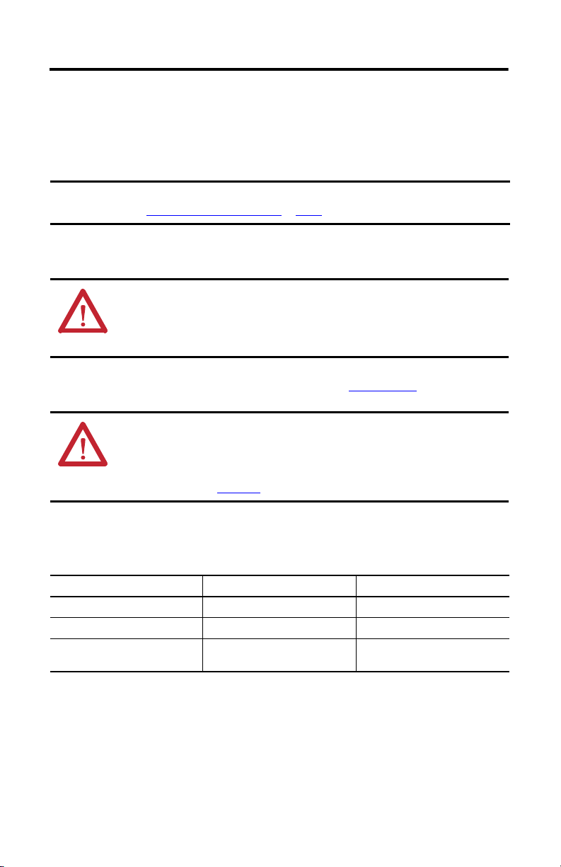
ATT EN TI ON : To avoid personal injury and/or damage to equipment, remove the IAM power
module from the power rail before setting the ground jumper.
By setting the ground jumper for ungrounded power configurations, you no longer maintain
line-to-neutral voltage protection.
To remove the IAM power module from the power rail, refer to the Kinetix 6200 and
Kinetix 6500 Modular Servo Drives User Manual, publication 2094-UM002
ATT EN TI ON : This drive contains electrostatic discharge (ESD) sensitive parts and assemblies.
You are required to follow static-control precautions when you install, test, service, or repair
this assembly. If you do not follow ESD control procedures, components can be damaged. If
you are not familiar with static control procedures, refer to Guarding Against Electrostatic
Damage, publication 8000-4.5.2
on page 7.
.
, or any other applicable ESD awareness handbook.
When using ungrounded input power in common-bus configurations, use this table to
determine where to set the ground jumper.
Ground Jumper to Set
Leader Drive Follower Drive Set the Jumper in This Drive
Kinetix 6200\6500 IAM module Kinetix 6200\6500 IAM module Leader drive
Kinetix 6200\6500 IAM module Non-Kinetix 6200\6500 drive Leader drive
Non-Kinetix 6200\6500 drive Kinetix 6200\6500 IAM module
Rockwell Automation Publication 2094-IN011D-EN-P - August 2013
Follower drive (if no setting exists in the
leader drive)
Page 5

Kinetix 6200 and Kinetix 6500 IAM and AM Power Modules 5
TIP
Set the Ground Jumper
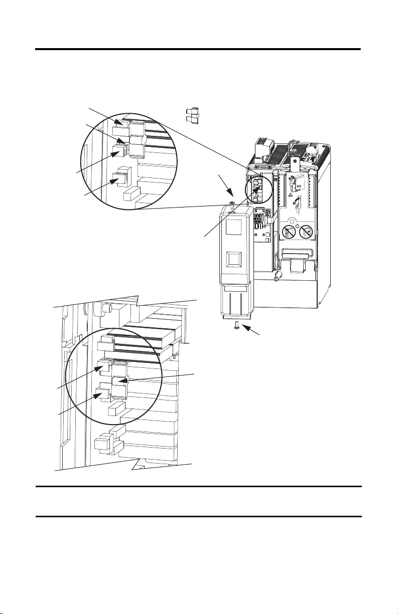
Follow these steps to set the ground jumper for ungrounded power.
1. Remove the top and bottom front-panel cover screws.
Refer to the figure on page 6
2. Pull the front panel cover straight out, as shown, and locate the ground jumper.
3. Move the ground jumper.
for an illustration of your actual hardware.
Access to the jumper improves when the Bulletin 2094 control module is removed
from the IAM power module.
To remove the control module from the IAM power module, refer to the Kinetix 6200
and Kinetix 6500 Modular Servo Drives User Manual, publication 2094-UM002.
IAM Power Module
2094-BC01-MP5-M (460V)
2094-BC01-M01-M (460V)
2094-BC02-M02-M (460V)
2094-BC04-M03-M (460V)
2094-BC07-M05-M (460V)
Configuration
Grounded (default) Ungrounded
P16 and P17 P18 and P19
4. Replace the IAM power module front panel cover and two screws.
Apply 1.6 N•m (14 lb•in) torque.
5. Mount the IAM power module back on the power rail.
Refer to Mount the IAM/AM Power Modules
on page 9 for help mounting your IAM
module.
Rockwell Automation Publication 2094-IN011D-EN-P - August 2013
Page 6
6 Kinetix 6200 and Kinetix 6500 IAM and AM Power Modules
IMPORTANT
Bottom Screw
Front Panel Cover
(removed)
Ground jumper set
for grounded configuration
(default setting).
Ground jumper set for
ungrounded configuration.
Top Sc rew
Removable Jumper
2094-BC01-MP5-M,
2094-BC01-M01-M,
2094-BC02-M02-M,
2094-BC04-M03-M, or
2094-BC07-M05-M
IAM (460V) Power Modules
Setting the IAM Power Module Ground Jumper (460V)
P16
P17
(behind P18)
P18
P19
P18
P19
Use the default jumper setting for grounded power configurations. Move the jumper, as
shown above, for ungrounded power.
Rockwell Automation Publication 2094-IN011D-EN-P - August 2013
Page 7

Kinetix 6200 and Kinetix 6500 IAM and AM Power Modules 7
Install the IAM/AM Power Modules
This procedure assumes you have prepared your panel, mounted your Bulletin 2094 power rail,
and understand how to bond your system. For installation instructions regarding equipment and
accessories not included here, refer to the instructions that came with those products.
SHOCK HAZARD: To avoid hazard of electrical shock, perform all mounting and wiring of the
Bulletin 2094 power rail and drive modules prior to applying power. Once power is applied,
connector terminals can have voltage present even when not in use.
ATT EN TI ON : Plan the installation of your system so that you can perform all cutting, drilling,
tapping, and welding with the system removed from the enclosure. Because the system is of
the open type construction, be careful to keep any metal debris from falling into it. Metal
debris or other foreign matter can become lodged in the circuitry and result in damage to
components.
You can use Bulletin 2094 mounting brackets to mount the power rail or line interface module
(LIM) over the AC line filter. Refer to the 2094 Mounting Brackets Installation Instructions,
publication 2094-IN008
Kinetix 6500 drive system.
The Bulletin 2094 power rail comes in lengths to support one IAM module and up to seven
additional AM/IPIM modules, or up to six additional AM/IPIM modules and one shunt
module. The connector pins for each slot are covered by a protective cover. The cover is designed
to protect the pins from damage and make sure that no foreign objects lodge between the pins
during installation. Refer to the Kinetix 6000 Power Rail Installation Instructions, publication
2094-IN003
, when installing your power rail.
, when using mounting brackets with your Kinetix 6200 and
ATT EN TI ON : To avoid damage to the power rail during installation, do not remove the
protective covers until the module for each slot is ready for mounting.
Rockwell Automation Publication 2094-IN011D-EN-P - August 2013
Page 8

8 Kinetix 6200 and Kinetix 6500 IAM and AM Power Modules
Highest Power Utilization
Lowest Power Utilizat ion
Integrated Axis Module
2094-BC01-MP5-M
IPIM Module
2094-SEPM-B24-S
Axis Module
2094-BMP5-M
Axis Module
2094-BMP5-M
Axis Module
2094-BMP5-M
Axis Module
2094-BMP5-M
Shunt Module
2094-BSP2
Slot Filler Module
2094-PRF
Determine Mounting Order
Mount the IAM, AM/IPIM, shunt, and slot-filler modules in the order (left to right) as shown.
Mount the axis modules and IPIM modules according to power utilization (highest to lowest)
from left to right starting with the highest power utilization. If power utilization is unknown,
position axis modules (highest to lowest) from left to right based on amp rating.
Power utilization is the average power (kW) consumed by a servo axis. If Motion Analyzer
software was used to size the axis, the calculated axis power required can be used for the power
utilization value. If Motion Analyzer software was not used, you can use the continuous power
value (kW) for each module to determine mounting order.
Kinetix 6200/6500 (400V-class) Axis Modules
Attribute 2094-BMP5-M 2094-BM01-M 2094-BM02-M 2094-BM03-M 2094-BM05-M
Continuous Power Output,
nom
Kinetix 6000M (400V-class) IPIM Module
Attribute 2094-SEPM-B24-S
Continuous Power Output, nom 15.0 kW
Module Mounting Order Example
1.8 kW 3.9 kW 6.6 kW 13.5 kW 22.0 kW
Rockwell Automation Publication 2094-IN011D-EN-P - August 2013
Page 9

Kinetix 6200 and Kinetix 6500 IAM and AM Power Modules 9
IMPORTANT
TIP
IMPORTANT
The IAM power module must be positioned in the leftmost slot of the power rail. Position your
AM/IPIM modules, shunt module, and slot-filler modules to the right of the IAM module.
The shunt module must be installed to the right of the last AM/IPIM module. Only slot-filler
modules can be installed to the right of the shunt module.
Do not mount the shunt module on power rails with a follower IAM module. Common-bus
follower IAM modules disable the internal, rail mounted, and external shunt modules.
SHOCK HAZARD: To avoid personal injury due to electrical shock, place a 2094-PRF slot-filler
module in all empty slots on the power rail.
Any power rail connector without a module installed disables the drive system; however, control
power is still present.
Mount the IAM/AM Power Modules
Follow these steps to mount the IAM, AM, IPIM, shunt, and slot-filler modules.
All modules mount to the power rail by using the same technique; however, only the IAM
module is shown.
1. Remove the protective covers from the power rail connectors.
The IAM module must be positioned in the leftmost slot of the power rail. Position
your axis modules, shunt module, and slot-filler modules to the right of the IAM
module.
2. Determine the next available slot and module for mounting.
ATT EN TI ON : To avoid damage to pins on the back of each IAM, AM, IPIM, shunt,
and slot-filler module, and to make sure that module pins mate properly with the
power rail, hang modules as shown in step 3
The power rail must be mounted vertically on the panel before hanging modules on
the power rail. Do not mount modules if the power rail is horizontal.
Rockwell Automation Publication 2094-IN011D-EN-P - August 2013
through step 6.
Page 10

10 Kinetix 6200 and Kinetix 6500 IAM and AM Power Modules
TIP
Slots for additional axis modules,
shunt module, or slot-filler modules.
Power R ail Slo t
Mounting Bracket
Power R ail
IAM or AM Power Module, IPIM,
Shunt, or Slot-filler Module
(IAM power module is shown)
Guide Pin
Holes
Power rail (side view)
in upright vertical position.
Guide Pins
Pivot module downward
and align with guide pins.
IAM or AM Power Module, IPIM,
Shunt, or Slot-filler Module, Rear View
(IAM power module is shown)
IAM or AM Power Module, IPIM,
Shunt, or Slot-filler Module, Side View
(IAM power module is shown)
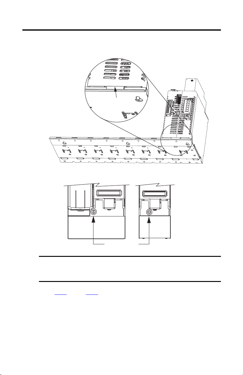
3. Hang the mounting bracket from the slot on the power rail.
4. Pivot module downward and align the guide pins on the power rail with the guide pin
holes in the back of the module.
Rockwell Automation Publication 2094-IN011D-EN-P - August 2013
The IAM module can have two or three power rail connectors and guide pins. The AM module
can have one or two, all other modules have one.
Page 11
Kinetix 6200 and Kinetix 6500 IAM and AM Power Modules 11
IMPORTANT
Power R ail
Bracket secured in slot.
IAM or AM Power Module, IPIM,
Shunt, or Slot-filler Module
(IAM power module is shown)
Mounting Screws
Bottom front view of
IAM module.
Bottom front view of
AM, shunt, or
slot-filler module
(AM modul e is shown).
5. Gently push the module against the power rail connectors and into the final mounting
position.
6. Use 2.26 N•m (20 lb•in) torque to tighten the mounting screws.
7. Repeat step 1
through step 6 for each AM, IPIM, shunt, or slot-filler module in your
Bulletin 2094 drive system.
There are two mounting screws when mounting 2094-BC04-M03-M, and
2094-BC07-M05-M (double-wide) IAM modules, and 2094-BM03-M and
2094-BM05-M (double-wide) AM modules.
Rockwell Automation Publication 2094-IN011D-EN-P - August 2013
Page 12

12 Kinetix 6200 and Kinetix 6500 IAM and AM Power Modules
1 2
DCDC+
L3
L2
L1
CONT EN-
CONT EN+
CTRL 2
CTRL 1
1 2
1 2 3 4 5 6
W
V
U
MBRK -
MBRK +
COM
PWR
DBRK -
DBRK +
1 2 3 4
1 2 3 4 5 6
1
4
5
2
3
6
7
9
8
IAM Power Module, Top View
(2094-BC01-MP5-M is shown)
IAM Power Module, Front View
(2094-BC01-MP5-M is shown)
Connector Data
Use these illustrations to identify the IAM and AM power module features and indicators.
IAM Power Module Features and Indicators
Item Description Item Description
1 Control power (CPD) connector 6 Motor/resistive brake (BC) connector
2 DC bus/AC input power (IPD) connector 7 Node address switch
3 Contactor Enable (CED) connector 8 Power-applied indicator
4 Motor cable shield clamp 9 Mounting screw
5 Motor power (MP) connector
ATT EN TI ON : To avoid damage to equipment, do not mount your Bulletin 2094 control
module to the power module when the Power-applied indicator is on. Remove all input
power from the IAM power module before mounting the control module.
Rockwell Automation Publication 2094-IN011D-EN-P - August 2013
Page 13

AM Power Module Features and Indicators
Item Description
1 Motor cable shield clamp
2 Motor power (MP) connector
3 Motor/resistive brake (BC) connector
4Power-applied indicator
5 Mounting screw
AM Power Module, Top View
(2094-BMP5-M is shown)
AM Power Module, Front View
(2094-BMP5-M is shown)
Kinetix 6200 and Kinetix 6500 IAM and AM Power Modules 13
MBRK -
MBRK +
DBRK DBRK +
W
V
U
COM
PWR
1 2 3 4
1 2 3 4 5 6
1
ATT EN TI ON : To avoid damage to equipment, do not mount your Bulletin 2094 control
module to the power module when the Power-applied indicator is on. Remove all input
power from the IAM power module before mounting the control module.
IAM/AM Module Connectors
Designator Description Connector Module
CPD Control input power (drive) 2-position plug/header IAM
IPD VAC input power (drive) and DC bus 6-position plug/header IAM
CED Contactor enable 2-position plug/header IAM
MP Motor power 4-position plug/header IAM/AM
BC Motor/resistive brake 6-position plug/header IAM/AM
2
4
3
5
Rockwell Automation Publication 2094-IN011D-EN-P - August 2013
Page 14

14 Kinetix 6200 and Kinetix 6500 IAM and AM Power Modules
IMPORTANT
IAM Input Connector Pinouts
Control Power Connector
CPD Pin Description Signal
1
2 CTRL 1
Control power VAC input
DC Bus and Input Power Connector
IPD Pin Description Signal
1
2 DC+
3 Chassis ground
An integral, unregulated power supply, consisting of AC line input, three-phase bridge
rectifier, and filter capacitors
CTRL 2
DC-
4
5 L2
6 L1
Three-phase input power
L3
Contactor Enable Connector
CED Pin Description Signal
1
2 CONT EN+
Relay-driven dry contact used in the safety string for a three-phase power contactor
CONT EN-
IAM /AM Motor Power and Brake Connector Pinouts
Motor Power Connector
MP Pin Descripti on S ignal
4 Chassis ground
3
2 V
1 U
Three-p hase motor power
To meet CE requirements, combined motor-power cable length for all axes on the same DC bus
must not exceed 240 m (787 ft) with 460V systems. Drive-to-motor power cables must not
exceed 90 m (295.5 ft).
W
Rockwell Automation Publication 2094-IN011D-EN-P - August 2013
Page 15

Kinetix 6200 and Kinetix 6500 IAM and AM Power Modules 15
IMPORTANT
L3
L2
L1
DCDC+
Motor Brake/Resistive Brake Connector
BC Pin Description Signal
6
5 MBRK+
Motor brake connections
MBRK-
4 Motor brake common COM
3 +24V brake input power (from LIM module or customer supplied) PWR
2
1 DBRK+
RBM module connections (from RBM module and safety string)
DBRK-
Power Wiring Requirements
Wire must be copper with 75 °C (167 °F) minimum rating. Phasing of main AC power is
arbitrary and earth ground connection is required for safe and proper operation.
The National Electrical Code and local electrical codes take precedence over the values and
methods provided.
IAM Module Power Wiring Requirements
Terminals Recommended
Pin Signal
IPD-1
IPD-2
IPD-3
IPD-4
IPD-5
IPD-6
CPD-1 CTRL 2
CPD-2 CTRL 1
CED-1 CONT EN-
CED-2 CONT EN+
Wire Size
2
mm
(AWG)
10…2.5
(8…14)
10…6
(8…10)
4…2.5
(12…14)
4…2.5
(12…14)
(2)
Rockwell Automation Publication 2094-IN011D-EN-P - August 2013
codes.
IAM Module
Cat. No.
2094-BC01-Mxx2094-BC02-M02-M
2094-BC04-M03-
2094-BC07-M05-
2094-BCxx-Mxx-
Module
IAM
(460V)
(1) Keep DC common-bus connections (le ader IAM to follower IAM module) as short as possib le.
(2) The actual gauge of the contactor enable wiring depends on the system configuration. Consult your machine builder, the NEC, and applicable loca l
Description
M
(1)
DC bus
and
M
VAC input power
M 30 (3)
Control i nput
power
M
Contac tor Enab le
Strip
Length
mm (in.)
10
(0.38)
16
(0.63)
10
(0.38)
Tor que V alu e
N•m (lb•in)
1.2…1.5
(10.6…13.2)
2.4…3.0
(21.6…26.5)
0.5…0.6
(4.4…5.3)
0.5…0.6
(4.4…5.3)
Page 16

16 Kinetix 6200 and Kinetix 6500 IAM and AM Power Modules
W
V
U
ATT EN TI ON : To avoid personal injury and/or equipment damage, make sure installation
complies with specifications regarding wire types, conductor sizes, branch circuit protection,
and disconnect devices. The National Electrical Code (NEC) and local codes outline provisions
for safely installing electrical equipment.
ATT EN TI ON : To avoid personal injury and/or equipment damage, make sure motor power
connectors are used only for connection purposes. Do not use them to turn the unit on and
off.
ATT EN TI ON : To avoid personal injury and/or equipment damage, make sure shielded power
cables are grounded to prevent potentially high voltages on the shield.
IAM/AM Module Power Wiring Requirements
IAM/AM Module
Cat. No.
2094-BC01-Mxx2094-BC02-M02-M
2094-BMP5-M
M
2094-BM01-
M
2094-BM02-
2094-BC04-M032094-BM03-M
2094-BC07-M052094-BM05-M
2094-BCxx-Mxx-
M
2094-BMxx-
M
M
M
M and
Description
Motor power
Brake power
Terminals Recommended
Pin Signal
MP-4
MP-3
MP-2
MP-1
BC-6
MBRK-
BC-5
MBRK+
BC-4
COM
BC-3
PWR
BC-2
DBRK-
BC-1
DBRK+
Strip
Wire Size
2
(AWG)
mm
Motor power cable depends on
motor/drive combination.
6…1.5
(10…16)
10…1.5
(8…16)
30…2.5
(3…14)
0.75 (18) 10 (0.38)
Length
mm (in.)
10 (0.38)
10 (0.38)
16 (0.63)
Torque Value
N•m (lb•in)
0.5…0.6
(4.4…5.3)
1.2…1.5
(10.6…13.2)
2.4…3.0
(21.6…26.5)
0.22…0.25
(1.9…2.2)
Rockwell Automation Publication 2094-IN011D-EN-P - August 2013
Page 17

Kinetix 6200 and Kinetix 6500 IAM and AM Power Modules 17
Motor Overload Protection
This servo drive uses solid-state motor overload protection that operates in accordance with
UL 508C. Motor overload protection is provided by algorithms (thermal memory) that predict
actual motor temperature based on operating conditions as long as control power is continuously
applied. However, when control power is removed, thermal memory is not retained.
In addition to thermal memory protection, this drive provides an input for an external
temperature sensor/thermistor device, embedded in the motor, to support the UL requirement
for motor overload protection.
Some motors supported by this drive do not contain temperature sensors/thermistors; therefore,
motor overload protection against excessive consecutive motor overloads with power cycling is
not supported.
This servo drive meets the following UL 508C requirements for solid-state overload protection.
Motor Overload Protection Trip Point Value
Ultimately 100% overload
Withi n 8 minute s 200% overloa d
Withi n 20 seco nds 600% overloa d
ATT EN TI ON : To avoid damage to your motor due to overheating caused by excessive,
successive motor overload trips, follow the wiring diagram provided in the user manual for
your motor and drive combination.
Refer to your servo drive user manual for the interconnect diagram that illustrates the wiring
between your motor and drive.
Rockwell Automation Publication 2094-IN011D-EN-P - August 2013
Page 18

18 Kinetix 6200 and Kinetix 6500 IAM and AM Power Modules
Additional Resources
These documents contain additional information concerning related products from
Rockwell Automation.
Resource Description
Kinetix 6200 and Kinetix 6500 Modular Multi-axis Ser vo Drive
User Manual, publication 2094-UM002
Kinetix 6000M Integrated Drive-Motor System User Manual,
publication 2094-UM003
Kinetix 6000 Power Rail Installation Instructions,
publication 2094-IN003
Kinetix 6000 Shunt Module Installation Instructions,
publication 2094-IN004
Line Interface Module Installation Instructions,
publication 2094-IN005
2094 Mounting Bracket Installation Instructions,
publication 2094-IN008
System Design for Control of Electrical Noise Reference Manual,
publication GMC-RM001
EMC Noise Management DVD, publication GMC-SP001
Kinetix Motion Control Selection Guide, publication GMC-SG001
Kinetix Servo Drives Specifications Technical Data,
publication GMC-TD003
Kinetix Motion Accessories Specifications Technical Data,
publication GMC-TD004
Rockwell Automation Configuration and Selection Tools,
websit e http://rockwellautomation.com/en/e-tools
Rockwell Automation Product Certification,
websit e http://rockwellautomation.com/products/certification
National Electrical Code, published by the National Fire
Protection Association of Boston, MA
Rockwell Automation Industri al Automation Glossary,
publication AG-7.1
Provides information on installing, configuring, startup,
troubleshooting, and applications for your Kinetix 6200 or
Kinetix 6500 servo drive system.
Provides information on installing, configuring, startup,
troubleshooting, and applications for your Kinetix 6000M
integrated drive-motor (IDM) system.
Provides information on the installation of your Bulletin 2094
Power R ail.
Provides information on the installation of your Bulletin 2094
Shunt Module.
Provides information on the installation and troubleshooting of
your Bulletin 2094 Line Interface Module (LIM).
Provides information on the installation of Bulletin 2094
Mounting Brackets.
Provides information, examples, and techniques designed to
minimize system failures caused by electrical noise.
Specifications, motor/servo- drive system combinations, and
accessories for Kinetix motion control products.
Provides product specifications for Kinetix Integrated Motion
over EtherNet/IP, Integrated Motion over sercos interface,
EtherNet/IP networking, and component servo drive families.
Provides product specifications for Bulletin 2090 motor and
interface cables, low-profile connector kits, drive power
components, and other servo drive accessory items.
Online product selection and system configuration tools,
including AutoCAD (DXF) drawings.
For declarations of conformity (DoC) currently available from
Rockwell Automation.
An article on wire sizes and types for grounding electrical
equipment.
A glossary of industrial automation terms and abbreviations.
You can view or download publications at http://www.rockwellautomation.com/literature
. To
order paper copies of technical documentation, contact your local Allen-Bradley distributor or
Rockwell Automation sales representative.
Rockwell Automation Publication 2094-IN011D-EN-P - August 2013
Page 19

Notes:
Kinetix 6200 and Kinetix 6500 IAM and AM Power Modules 19
Rockwell Automation Publication 2094-IN011D-EN-P - August 2013
Page 20

Rockwell Automation Support
Rockwell Automation provides tec hnical information on the Web to assist you in using its products.
At http://www.rockwellautomation.com/support
service packs. You can also visit our Support Center at https://rockwellautomation.custhelp.com/
and forums, technical information, FAQs, and to sign up for product notification updates.
In addition, we offer multiple support programs for installation, configuration, and troubleshooting. For more information, contact
your local distributor or Rockwell Automation representative, or visit http://www.rockwellautomation.com/services/online-phone
Installation Assistance
If you experience a problem within the first 24 hours of installation, please review the information that's contained in this manual.
You can also contact a special Customer Support number for initial help in getting your product up and running.
United States or Canada 1.440.646.3434
Outside United States or
Canada
Use the Wor ldwi de Loc ator
http://www.rockwellautomation.com/rockwellautomation/support/overview.page
local Rockwell Automation representative.
New Product Satisfaction Return
Rockwell Automation tests all of its products to help ensure that they are fully operational when shipped from the manufacturing
facility. However, if your product is not functioning and needs to be returned, follow these procedures.
you can find technical and application notes, sample code, and links to software
for software updates, support chats
at
, or contact your
.
United States
Outside United States Please contact your local Rockwell Automation representative for the return procedure.
Contact your distributor. You must provide a Customer Support case number (call the phone number
above to obtain one) to your distributor to complete the return process.
Documentation Feedback
Your comments will help us serve your documentation needs better. If you have any suggestions on how to improve this document,
complete this form, publication RA-DU002
Allen-Bradley, CompactLogix, ControlLogix, Kinetix, Rockwell Sof tware, Rockwell Automation, and SoftLogix are trademarks of
Rockwell Automation, Inc.
Trademarks not belonging to Rockwell Automation are property of their respective companies.
Rockwell Otomasyon Ticaret A.Ş., Kar Plaza İş Merkezi E Blok Kat:6 34752 İçerenköy, İstanbul, Tel: +90 (216) 5698400
Publication 2094-IN011D-EN-P - August 2013 PN-215235
Supersedes Publication 2094-IN011C-EN-P - March 2010 Copyright © 2013 Rock well Automation, Inc. All rights reserved. Printed in the U.S.A.
, available at http://www.rockwellautomation.com/literature/.
 Loading...