

Page 1

Installation Instructions
Kinetix 6000 Axis Module and Shunt Module
Catalog Numbers
2094-AMxx, 2094-BMxx
2094-AMxx-S, 2094-BMxx-S
2094-BSP2
Topic Page
About This Publication 1
Important User Information 2
Before You Begin 3
Installing the Kinetix 6000 Drive Modules 4
Additional Resources 8
About This Publication
This publication provides installation instructions for modules that
mount to the Kinetix 6000 power rail. These include the axis module
(AM), shunt module (SM).
For the slot filler module installation instructions, refer to the
Kinetix 6000 Slot Filler Module Installation Instructions, publication
2094-IN006.
For information on installing the Kinetix 6000 drive system, refer to
the Kinetix 6000 Multi-axis Servo Drive User Manual, publication
2094-UM001.
For installation information regarding equipment and accessories not
included here, refer to Additional Resources on page 8 or the
information available for those products.
1 Publication 2094-IN004D-EN-P — September 2006
Page 2
2 Kinetix 6000 Axis Module and Shunt Module
T
SHOCK HAZARD
D
Important User Information
Solid state equipment has operational characteristics differing from those of
electromechanical equipment. Safety Guidelines for the Application, Installation and
Maintenance of Solid State Controls (publication SGI-1.1 available from your local Rockwell
Automation sales office or online at http://literature.rockwellautomation.com
) describes
some important differences between solid state equipment and hard-wired
electromechanical devices. Because of this difference, and also because of the wide variety
of uses for solid state equipment, all persons responsible for applying this equipment must
satisfy themselves that each intended application of this equipment is acceptable.
In no event will Rockwell Automation, Inc. be responsible or liable for indirect or
consequential damages resulting from the use or application of this equipment.
The examples and diagrams in this manual are included solely for illustrative purposes.
Because of the many variables and requirements associated with any particular installation,
Rockwell Automation, Inc. cannot assume responsibility or liability for actual use based on
the examples and diagrams.
No patent liability is assumed by Rockwell Automation, Inc. with respect to use of
information, circuits, equipment, or software described in this manual.
Reproduction of the contents of this manual, in whole or in part, without written permission
of Rockwell Automation, Inc., is prohibited.
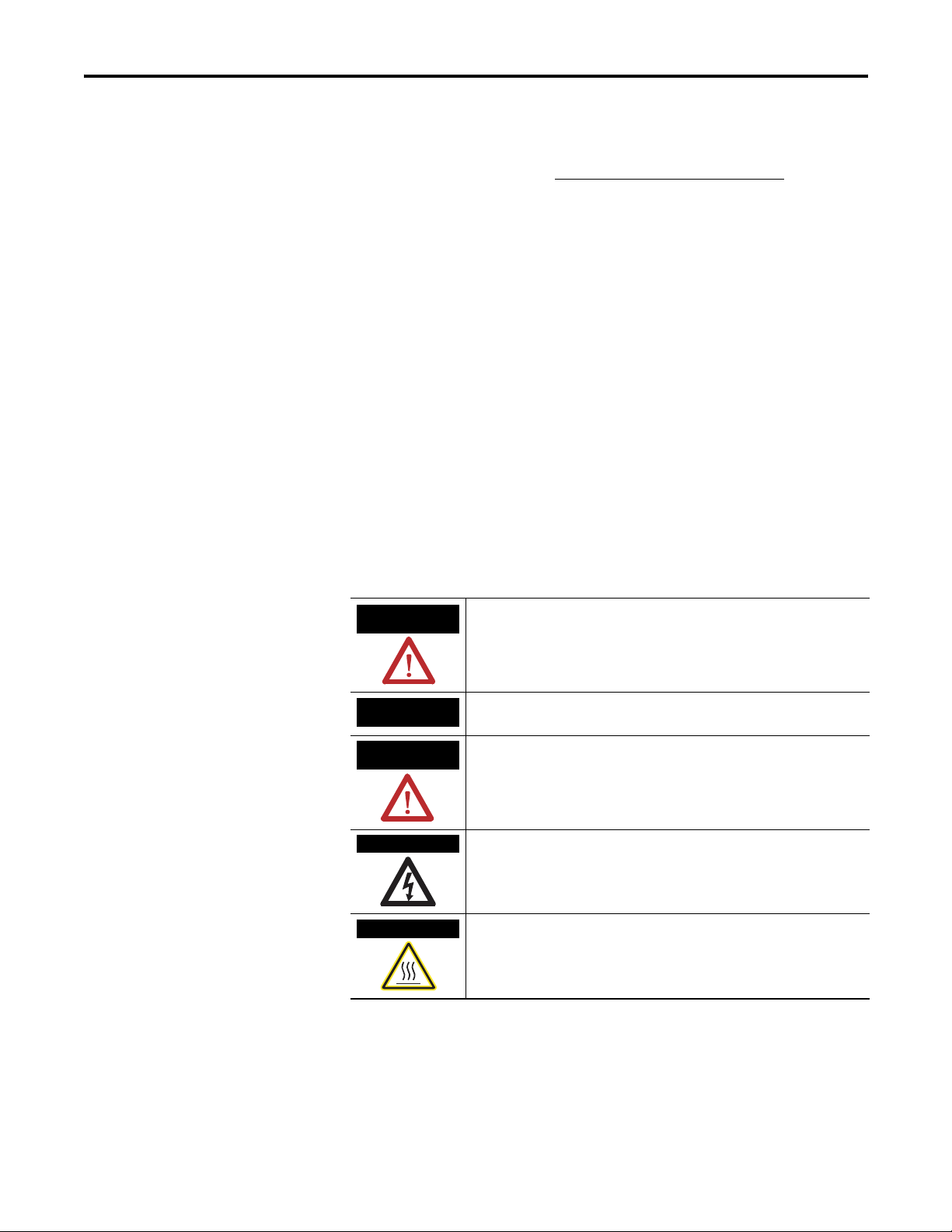
Throughout this manual, when necessary, we use notes to make you aware of safety
considerations.
WARNING
Identifies information about practices or circumstances that can cause
an explosion in a hazardous environment, which may lead to personal
injury or death, property damage, or economic loss.
IMPORTAN
ATTENTION
Identifies information that is critical for successful application and
understanding of the product.
Identifies information about practices or circumstances that can lead
to personal injury or death, property damage, or economic loss.
Attentions help you to identify a hazard, avoid a hazard, and recognize
the consequences.
Labels may be located on or inside the equipment, for example, a
drive or motor, to alert people that dangerous voltage may be present.
BURN HAZAR
Labels may be located on or inside the equipment, for example, a
drive or motor, to alert people that surfaces may be at dangerous
temperatures.
Allen-Bradley, Kinetix, and Rockwell Automation are trademarks of Rockwell Automation, Inc.
Trademarks not belonging to Rockwell Automation are property of their respective companies.
Publication 2094-IN004D-EN-P — September 2006
Page 3
Kinetix 6000 Axis Module and Shunt Module 3
Before You Begin
Remove all packing material, wedges, and braces from within and
around the components. After unpacking, check the item name-plate
catalog number against the purchase order.
Drive Component Box C ontents
Drive Component Ships With
• Wiring plugs for motor power (MP) and motor/resistive brake
power (BC).
Axis Module (AM)
Shunt Module (SM)
• Wiring plug header for safe-off (SO) connector and motion
allowed jumper.
• Installation Instructions, publication 2094-IN004.
• Wiring plug for an external shunt resistor (RC).
• Wiring plug for the thermal switch (TS).
• Installation Instructions, publication 2094-IN004.
Motor and auxiliary feedback and I/O connectors are not provided.
Refer to the Kinetix Motion Control Selection Guide, publication
GMC-SG001, for connector kit catalog numbers.
IMPORTANT
The integrated axis module (IAM) must be positioned in the
leftmost slot of the power rail. Position your axis modules (AM),
shunt module (SM), and slot filler modules (PRF) to the right of
the IAM.
ATTENTION
The SM must be installed to the right of the last AM. Only slot
filler modules may be installed to the right of the SM.
Do not mount the SM on power rails with a follower IAM.
Common-bus follower IAMs will disable the internal, rail
mounted, and external shunt modules.
This drive contains ESD (Electrostatic Discharge) sensitive parts
and assemblies. You are required to follow static control
precautions when you install, test, service, or repair this
assembly. If you do not follow ESD control procedures,
components can be damaged. If you are not familiar with static
control procedures, refer to Allen-Bradley publication
8000-4.5.2, Guarding Against Electrostatic Damage or any other
applicable ESD Protection Handbook.
Publication 2094-IN004D-EN-P — September 2006
Page 4

4 Kinetix 6000 Axis Module and Shunt Module
SHOCK HAZARD
Installing the Kinetix 6000 Drive Modules
These procedures assume you have mounted your power rail and
integrated axis module (IAM). Each power rail accommodates one
IAM and up to seven additional modules (either axis or shunt). You
must mount a slot filler in any slot not occupied by another module.
To avoid personal injury due to electrical shock, place a slot
filler module (catalog number 2094-PRF) in any empty slot on
the power rail.
Any power rail connector without a module installed will
disable the Kinetix 6000 system, however control power will
still be present.
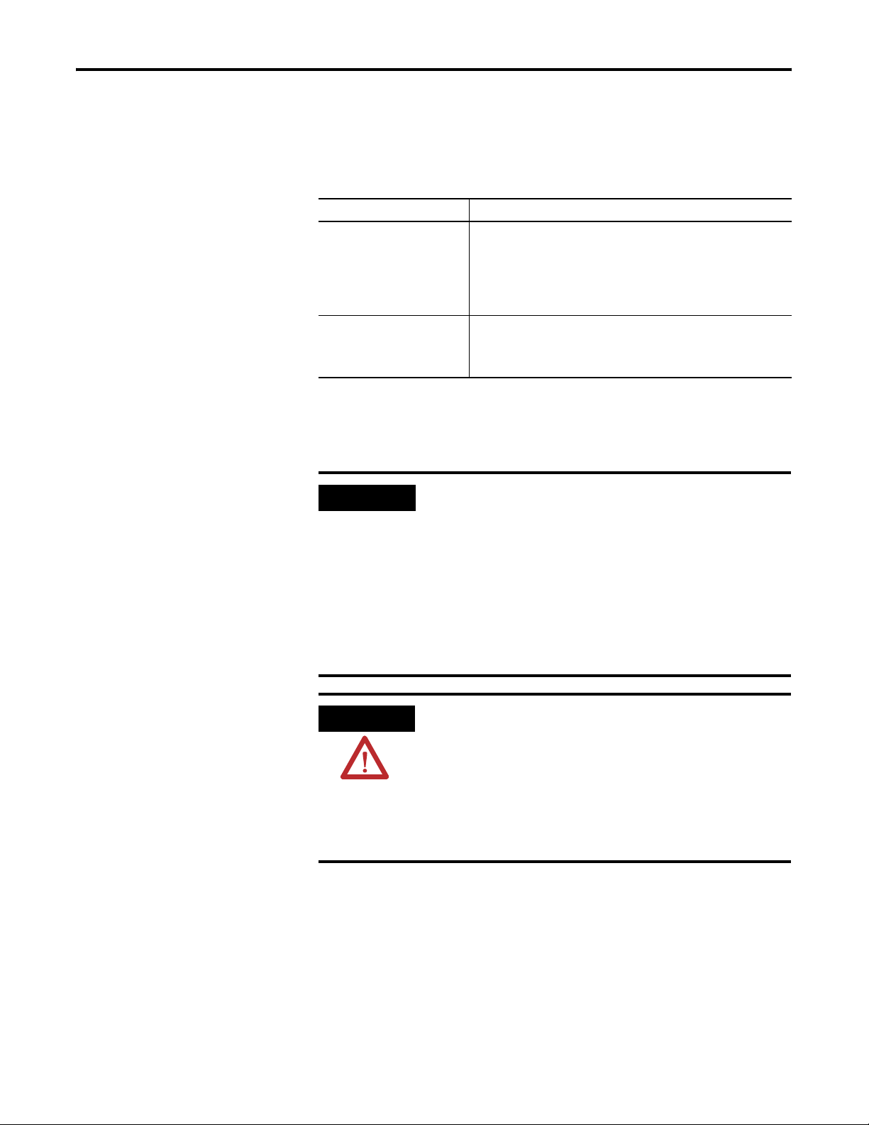
Determining Mounting Order
IMPORTANT
Mount axis modules according to ampere rating (highest to
lowest) from left to right starting with the highest ampere
rating.
Integrated Axis Module
2094-AC09-M02
Module Mounting Order
Highest Power Utilization or Amp Rating
Axis Module
2094-AM02
Axis Module
2094-AM02
Axis Module
Lowest Power Utilization or Amp Rating
2094-AM02
Axis Module
2094-AM01
Axis Module
2094-AM01
Shunt Module
2094-BSP2
Slot Filler Module
2094-PRF
Publication 2094-IN004D-EN-P — September 2006
ATTENTION
To avoid damage to the power rail during installation, do not
remove the protective boots until the module for each slot is
ready for mounting.
Page 5

Kinetix 6000 Axis Module and Shunt Module 5
Mounting the Modules
Follow these steps to mount the IAM, AM, SM, and PRF modules. All
modules mount to the power rail using the same technique
(integrated axis module is shown).
1. Remove the protective boots from the power rail connectors.
IMPORTANT
The IAM must be positioned in the leftmost slot of the
power rail. Position your axis modules, shunt module, and
slot filler modules to the right of the IAM.
2. Determine the next available slot and module for mounting.
3. Remove the label (applied to back and side of module) covering
the pins that mate with the power rail.
ATTENTION
To avoid damage to the pins located on the back of each
module (IAM, AM, SM, and PRF) and to make sure that
module pins mate properly with the power rail, hang
modules as shown in Steps 4...7.
The power rail must be mounted vertically on the panel
before hanging modules on the power rail. Do not mount
modules if the power rail is horizontal.
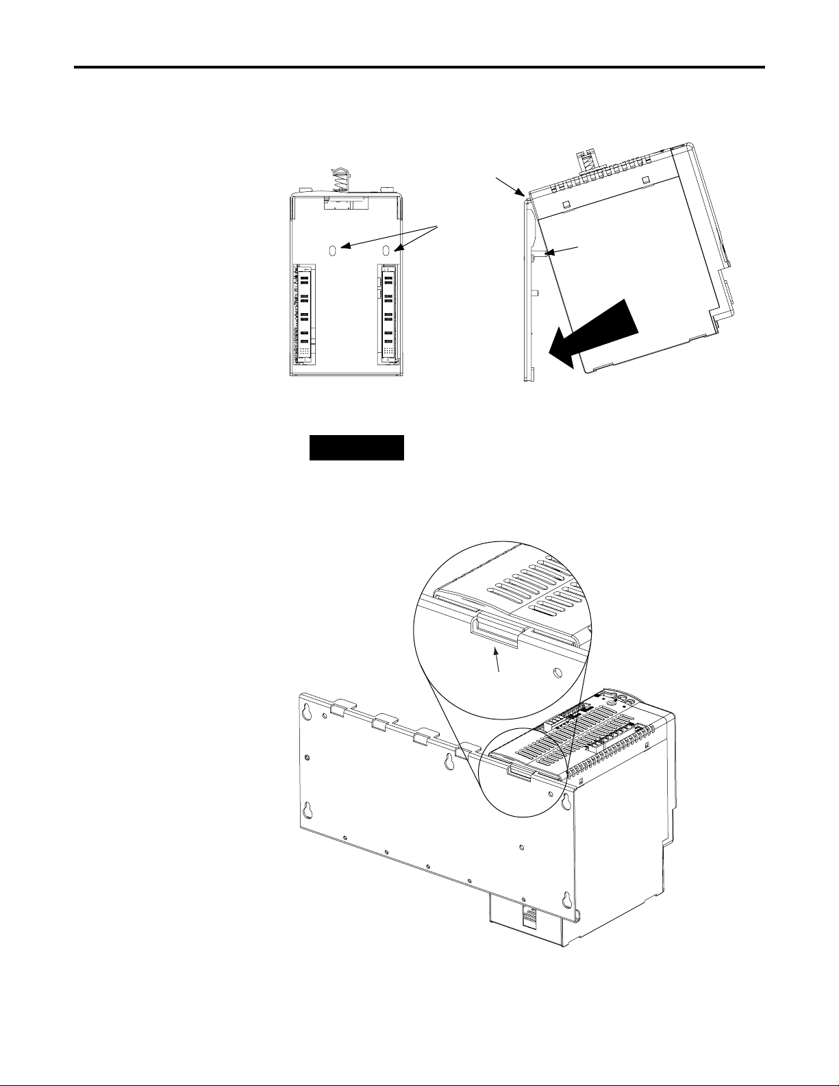
4. Hang the mounting bracket from the slot on the power rail.
Slots for additional axis modules,
shunt module, or slot filler.
Power Rail
Mounting Bracket
Power Rail Slot
Integrated Axis Module
Publication 2094-IN004D-EN-P — September 2006
Page 6
6 Kinetix 6000 Axis Module and Shunt Module
5. Pivot module downward and align the guide pins on the power
rail with the guide pin holes in the back of the module.
Integrated Axis Module
(rear view)
Pivot module downward
and align with guide pins.
Guide Pin
Holes
Power rail
(side view)
in upright
vertical position.
Guide Pins
Integrated Axis Module
(side view)
Power Rail
TIP
The IAM can have two or three power rail connectors and guide
pins, the AM can have one or two, all other modules have one.
6. Gently push the module against the power rail connectors and
into the final mounting position.
Bracket secured in slot.
Publication 2094-IN004D-EN-P — September 2006
Integrated Axis Module
Page 7

Kinetix 6000 Axis Module and Shunt Module 7
7. Use 2.26 Nm (20 lb-in) torque to tighten the mounting screws.
Bottom front view of
double-wide IAM or AM
(AM is shown).
Bottom front view of
single-wide AM, SM, or PRF
(AM is shown).
Mounting Screws
IMPORTANT
There are two mounting screws when mounting
2094-AC32-M05, -BC04-M03, and -BC07-M05 (double-wide)
IAMs and 2094-AM05, -BM03, and -BM05 (double-wide) AMs.
8. Repeat Steps 1...7 for each AM, SM, or PRF module
.
Replacing Kinetix 6000 Drive Components
For Kinetix 6000 drive component removal and replacement
procedures, refer to the Kinetix 6000 Multi-axis Servo Drive User
Manual, publication number 2094-UM001.
Publication 2094-IN004D-EN-P — September 2006
Page 8

Additional Resources
The following documents contain additional information concerning
related Allen-Bradley products.
For Read This Document Publication Number
Information on installing, configuring, startup, troubleshooting,
and applications for your Kinetix 6000 servo drive system
Information on the installation of your Kinetix 6000 power rail Kinetix 6000 Power Rail Installation Instructions 2094-IN003
Information on the installation of your Kinetix 6000 slot filler
module
Information, examples, and techniques designed to minimize
system failures caused by electrical noise
Specifications, motor/servo-drive system combinations, and
accessories for Kinetix motion control products
Online product selection and system configuration tools,
including AutoCAD (DXF) drawings
For declarations of conformity (DoC) currently available from
Rockwell Automation
A glossary of industrial automation terms and abbreviations Rockwell Automation Industrial Automation Glossary AG-7.1
Kinetix 6000 User Manual 2094-UM001
Kinetix 6000 Slot Filler Module Installation Instructions 2094-IN006
System Design for Control of Electrical Noise Reference
Manual
EMC Noise Management DVD GMC-SP001
Kinetix Motion Control Selection Guide GMC-SG001
Rockwell Automation Configuration and Selection Tools
website
Rockwell Automation Product Certification website
GMC-RM001
http://www.ab.com/
e-tools
http://
www.rockwellautomation.
com/products/certification
You can view or download publications at
http://literature.rockwellautomation.com
. To order paper copies of
technical documentation, contact your local Rockwell Automation
distributor or sales representative.
Publication 2094-IN004D-EN-P — September 20068 PN 313666-P04
Supersedes Publication 2094-IN004C-EN -P — September 2005 Copyright © 2006 Rockwell Automatio n, Inc. All rights reserved. Printed in the U.S.A.
 Loading...