

Page 1
Kinetix 2000 Multi-axis
Servo Drive
Catalog Numbers
2093-AC05-MP1, 2093-AC05-MP2,
2093-AC05-MP5
2093-AM01, 2093-AM02
2093-AMP1, 2093-AMP2, 2093-AMP5
2093-PRS1, 2093-PRS2, 2093-PRS3,
2093-PRS4, 2093-PRS5, 2093-PRS7,
2093-PRS8S
2093-ASP06
2093-PRF
User Manual
Page 2
Important User Information
Solid state equipment has operational characteristics differing from those of
electromechanical equipment. Safety Guidelines for the Application,
Installation and Maintenance of Solid State Controls (publication SGI-1.1
available from your local Rockwell Automation sales office or online at
http://literature.rockwellautomation.com
) describes some important
differences between solid state equipment and hard-wired electromechanical
devices. Because of this difference, and also because of the wide variety of uses
for solid state equipment, all persons responsible for applying this equipment
must satisfy themselves that each intended application of this equipment is
acceptable.
In no event will Rockwell Automation, Inc. be responsible or liable for indirect
or consequential damages resulting from the use or application of this
equipment.
The examples and diagrams in this manual are included solely for illustrative
purposes. Because of the many variables and requirements associated with any
particular installation, Rockwell Automation, Inc. cannot assume responsibility
or liability for actual use based on the examples and diagrams.
No patent liability is assumed by Rockwell Automation, Inc. with respect to
use of information, circuits, equipment, or software described in this manual.
Reproduction of the contents of this manual, in whole or in part, without
written permission of Rockwell Automation, Inc., is prohibited.
Throughout this manual, when necessary, we use notes to make you aware of
safety considerations.
WARNING
IMPORTANT
ATTENTION
WARNING
BURN HAZ-
Identifies information about practices or circumstances that can cause
an explosion in a hazardous environment, which may lead to personal
injury or death, property damage, or economic loss.
Identifies information that is critical for successful application and
understanding of the product.
Identifies information about practices or circumstances that can lead to
personal injury or death, property damage, or economic loss. Attentions
help you identify a hazard, avoid a hazard, and recognize the
consequence
Labels may be on or inside the equipment, for example, a drive or motor,
to alert people that dangerous voltage may be present.
Labels may be on or inside the equipment, for example, a drive or motor,
to alert people that surfaces may reach dangerous temperatures.
Allen-Bradley, CompactLogix, ControlFlash, ControlLogix, DriveExplorer, Kinetix, Logix5000, RSLogix, RSLogix 5000, SoftLogix, SCANport,
Rockwell Automation, and TechConnect are trademarks of Rockwell Automation, Inc.
Trademarks not belonging to Rockwell Automation are the property of their respective companies.
Page 3

Start
Planning the Kinetix 2000 Drive
System Installation
Table of Contents
Preface
About This Publication . . . . . . . . . . . . . . . . . . . . . . . . . . . . . . . . . . . . . . 9
Who Should Use This Manual . . . . . . . . . . . . . . . . . . . . . . . . . . . . . . . . 9
Conventions Used in This Manual . . . . . . . . . . . . . . . . . . . . . . . . . . . . . 9
Additional Resources. . . . . . . . . . . . . . . . . . . . . . . . . . . . . . . . . . . . . . . 10
Chapter 1
Introduction. . . . . . . . . . . . . . . . . . . . . . . . . . . . . . . . . . . . . . . . . . . . . . 11
About the Kinetix 2000 Drive System . . . . . . . . . . . . . . . . . . . . . . . . . 12
Catalog Number Explanation . . . . . . . . . . . . . . . . . . . . . . . . . . . . . . . . 16
Agency Compliance. . . . . . . . . . . . . . . . . . . . . . . . . . . . . . . . . . . . . . . . 17
CE Requirements (System without LIM). . . . . . . . . . . . . . . . . . . . 17
CE Requirements (System with LIM) . . . . . . . . . . . . . . . . . . . . . . 18
Chapter 2
Introduction. . . . . . . . . . . . . . . . . . . . . . . . . . . . . . . . . . . . . . . . . . . . . . 19
System Design Guidelines. . . . . . . . . . . . . . . . . . . . . . . . . . . . . . . . . . . 19
System Mounting Requirements. . . . . . . . . . . . . . . . . . . . . . . . . . . 19
Transformer Selection. . . . . . . . . . . . . . . . . . . . . . . . . . . . . . . . . . . 20
Circuit Breaker/Fuse Selection. . . . . . . . . . . . . . . . . . . . . . . . . . . . 21
Enclosure Selection. . . . . . . . . . . . . . . . . . . . . . . . . . . . . . . . . . . . . 21
Minimum Clearance Requirements . . . . . . . . . . . . . . . . . . . . . . . . 24
Minimizing Electrical Noise . . . . . . . . . . . . . . . . . . . . . . . . . . . . . . . . . 26
Bonding Modules . . . . . . . . . . . . . . . . . . . . . . . . . . . . . . . . . . . . . . 26
Bonding Multiple Subpanels. . . . . . . . . . . . . . . . . . . . . . . . . . . . . . 27
Establishing Noise Zones. . . . . . . . . . . . . . . . . . . . . . . . . . . . . . . . 28
Cable Categories for Kinetix 2000 Systems . . . . . . . . . . . . . . . . . . 34
Noise Reduction Guidelines for Drive Accessories . . . . . . . . . . . 36
Chapter 3
Mounting the Kinetix 2000 Drive
System
Introduction. . . . . . . . . . . . . . . . . . . . . . . . . . . . . . . . . . . . . . . . . . . . . . 37
Installing the 2093 Power Rail . . . . . . . . . . . . . . . . . . . . . . . . . . . . . . . 37
Determining Mounting Order . . . . . . . . . . . . . . . . . . . . . . . . . . . . . . . 38
2093-PRS8S Module Configuration . . . . . . . . . . . . . . . . . . . . . . . . 39
Mount the Modules . . . . . . . . . . . . . . . . . . . . . . . . . . . . . . . . . . . . . . . . 40
Mounting the Line Interface Module . . . . . . . . . . . . . . . . . . . . . . . . . . 41
Segregating Power and Logic Wires . . . . . . . . . . . . . . . . . . . . . . . . . . . 42
Chapter 4
Kinetix 2000 Connector Data
3 Publication 2093-UM001A-EN-P — March 2007
Introduction. . . . . . . . . . . . . . . . . . . . . . . . . . . . . . . . . . . . . . . . . . . . . . 43
Locating IAM/AM Connectors and Indicators . . . . . . . . . . . . . . . . . 43
I/O Connector Pinouts . . . . . . . . . . . . . . . . . . . . . . . . . . . . . . . . . 46
Motor Feedback Connector Pinouts . . . . . . . . . . . . . . . . . . . . . . . 48
IAM Input Connector Pinouts . . . . . . . . . . . . . . . . . . . . . . . . . . . . 49
IAM and AM Motor Power and Brake Connector Pinouts . . . . . 50
IAM/AM Signal Specifications Explained. . . . . . . . . . . . . . . . . . . . . . 51
Page 4

4
Connecting the Kinetix 2000 Drive
System
Digital Inputs . . . . . . . . . . . . . . . . . . . . . . . . . . . . . . . . . . . . . . . . . . 51
SERCOS Connections. . . . . . . . . . . . . . . . . . . . . . . . . . . . . . . . . . . 53
Contactor Enable Relay . . . . . . . . . . . . . . . . . . . . . . . . . . . . . . . . . . 53
Motor Brake Relay . . . . . . . . . . . . . . . . . . . . . . . . . . . . . . . . . . . . . . 54
Control Power Input . . . . . . . . . . . . . . . . . . . . . . . . . . . . . . . . . . . . 55
Feedback Specifications Explained . . . . . . . . . . . . . . . . . . . . . . . . . . . . 57
Motor and Auxiliary Feedback Specifications . . . . . . . . . . . . . . . . 57
Motor Encoder Feedback Specifications . . . . . . . . . . . . . . . . . . . . 58
Feedback Power Supply. . . . . . . . . . . . . . . . . . . . . . . . . . . . . . . . . . 59
Locating Shunt Module Connectors and Indicators. . . . . . . . . . . . . . . 60
Chapter 5
Introduction . . . . . . . . . . . . . . . . . . . . . . . . . . . . . . . . . . . . . . . . . . . . . . 61
Basic Wiring Requirements . . . . . . . . . . . . . . . . . . . . . . . . . . . . . . . . . . 61
Building Your Own Cables . . . . . . . . . . . . . . . . . . . . . . . . . . . . . . . 62
Routing Power and Signal Wiring . . . . . . . . . . . . . . . . . . . . . . . . . . 62
Determining Your Type of Input Power . . . . . . . . . . . . . . . . . . . . . . . 63
Grounded Three-phase Power Configurations . . . . . . . . . . . . . . . 63
Ungrounded Three-phase Power Configurations . . . . . . . . . . . . . 65
Grounded Single-phase Power Configurations . . . . . . . . . . . . . . . 66
DC Common Bus Configurations. . . . . . . . . . . . . . . . . . . . . . . . . . . . . 67
Common Bus Fusing Requirements . . . . . . . . . . . . . . . . . . . . . . . . 68
Setting the Ground Jumper in Ungrounded Power Configurations . . 69
Set Ground Jumper . . . . . . . . . . . . . . . . . . . . . . . . . . . . . . . . . . . . . 69
Grounding Your System . . . . . . . . . . . . . . . . . . . . . . . . . . . . . . . . . . . . 71
Grounding Your System to the Subpanel. . . . . . . . . . . . . . . . . . . . 71
Grounding Multiple Subpanels . . . . . . . . . . . . . . . . . . . . . . . . . . . . 72
Power Wiring Requirements . . . . . . . . . . . . . . . . . . . . . . . . . . . . . . . . . 73
Wiring Guidelines. . . . . . . . . . . . . . . . . . . . . . . . . . . . . . . . . . . . . . . . . . 76
Wiring the LIM Connectors . . . . . . . . . . . . . . . . . . . . . . . . . . . . . . . . . 77
Wiring the Auxiliary Input Power (APL) Connector . . . . . . . . . . . 77
Wiring the VAC LINE (IPL) Connector . . . . . . . . . . . . . . . . . . . . 77
Wiring the VAC LOAD (OPL) Connector . . . . . . . . . . . . . . . . . . 78
Wiring the Control Power Output (CPL) Connector . . . . . . . . . . 79
Wiring the Auxiliary Power Output (P2L) Connector . . . . . . . . . . 79
Wiring the Brake Power Output (24V dc) Connector . . . . . . . . . . 80
Wiring the IAM/AM Connectors . . . . . . . . . . . . . . . . . . . . . . . . . . . . . 81
Wiring the Control Power (CPD) Connector. . . . . . . . . . . . . . . . . 81
Wiring the Input Power (IPD) Connector . . . . . . . . . . . . . . . . . . . 82
Wiring the Contactor Enable (CED) Connector . . . . . . . . . . . . . . 84
Wiring the Motor Power (MP) Connector . . . . . . . . . . . . . . . . . . . 85
Wiring the Motor Brake (BC) Connector . . . . . . . . . . . . . . . . . . . . 89
Feedback and I/O Cable Connections . . . . . . . . . . . . . . . . . . . . . . . . . 92
Flying-lead Feedback Cable Pin-outs . . . . . . . . . . . . . . . . . . . . . . . 93
Wiring Feedback and I/O Connectors . . . . . . . . . . . . . . . . . . . . . . . . . 95
Connecting Premolded Motor Feedback Cables . . . . . . . . . . . . . . 95
Wiring Low-profile Connector Kits . . . . . . . . . . . . . . . . . . . . . . . . 95
Publication 2093-UM001A-EN-P — March 2007
Page 5

5
Configure and Startup the
Kinetix 2000 Drive System
Wiring 15-pin Panel-mounted Breakout Kit . . . . . . . . . . . . . . . . . 97
Wiring 44-pin Panel-mounted Breakout Kit . . . . . . . . . . . . . . . . . 97
Shunt Module Connections. . . . . . . . . . . . . . . . . . . . . . . . . . . . . . . . . . 98
Connecting Your SERCOS Fiber-optic Cables . . . . . . . . . . . . . . . . . . 99
SERCOS Cables . . . . . . . . . . . . . . . . . . . . . . . . . . . . . . . . . . . . . . 101
Chapter 6
Introduction. . . . . . . . . . . . . . . . . . . . . . . . . . . . . . . . . . . . . . . . . . . . . 103
System Configuration Requirements . . . . . . . . . . . . . . . . . . . . . . . . . 103
Configure the IAM/AM . . . . . . . . . . . . . . . . . . . . . . . . . . . . . . . . . . . 103
Configure the Logix SERCOS Interface Module . . . . . . . . . . . . . . . 109
Configure the Logix Controller . . . . . . . . . . . . . . . . . . . . . . . . . . 109
Configure the SERCOS Interface Module. . . . . . . . . . . . . . . . . . 110
Configure the Kinetix 2000 Modules. . . . . . . . . . . . . . . . . . . . . . 113
Configure the Motion Group . . . . . . . . . . . . . . . . . . . . . . . . . . . . 118
Configure Axis Properties. . . . . . . . . . . . . . . . . . . . . . . . . . . . . . . 118
Download the Program. . . . . . . . . . . . . . . . . . . . . . . . . . . . . . . . . 122
Apply Power to the
Kinetix 2000 Drive . . . . . . . . . . . . . . . . . . . . . . . . . . . . . . . . . . . . . 123
Test and Tune the Axes. . . . . . . . . . . . . . . . . . . . . . . . . . . . . . . . . . . . 126
Test the Axes. . . . . . . . . . . . . . . . . . . . . . . . . . . . . . . . . . . . . . . . . 126
Tune the Axes . . . . . . . . . . . . . . . . . . . . . . . . . . . . . . . . . . . . . . . . 128
Troubleshooting the Kinetix 2000
Drive System
Removing and Replacing the
Kinetix 2000 Drive Modules
Chapter 7
Introduction. . . . . . . . . . . . . . . . . . . . . . . . . . . . . . . . . . . . . . . . . . . . . 133
Safety Precautions . . . . . . . . . . . . . . . . . . . . . . . . . . . . . . . . . . . . . . . . 133
Interpreting Status Indicators . . . . . . . . . . . . . . . . . . . . . . . . . . . . . . . 134
Error Codes . . . . . . . . . . . . . . . . . . . . . . . . . . . . . . . . . . . . . . . . . . 134
IAM/AM Status Indicators . . . . . . . . . . . . . . . . . . . . . . . . . . . . . 139
SM Status Indicators . . . . . . . . . . . . . . . . . . . . . . . . . . . . . . . . . . . 140
Troubleshooting General System Problems. . . . . . . . . . . . . . . . . . . . 143
Logix/Drive Fault Behavior . . . . . . . . . . . . . . . . . . . . . . . . . . . . . 145
Chapter 8
Introduction. . . . . . . . . . . . . . . . . . . . . . . . . . . . . . . . . . . . . . . . . . . . . 149
Before You Begin . . . . . . . . . . . . . . . . . . . . . . . . . . . . . . . . . . . . . . . . 149
Remove Modules from the Power Rail . . . . . . . . . . . . . . . . . . . . . . . 150
Replace Modules on the Power Rail. . . . . . . . . . . . . . . . . . . . . . . . . . 151
Remove the Power Rail. . . . . . . . . . . . . . . . . . . . . . . . . . . . . . . . . . . . 151
Replace the Power Rail . . . . . . . . . . . . . . . . . . . . . . . . . . . . . . . . . . . . 152
Publication 2093-UM001A-EN-P — March 2007
Page 6

6
Specifications and Dimensions
Appendix A
Introduction . . . . . . . . . . . . . . . . . . . . . . . . . . . . . . . . . . . . . . . . . . . . . 153
Power Specifications . . . . . . . . . . . . . . . . . . . . . . . . . . . . . . . . . . . . . . 154
Converter Power Specifications . . . . . . . . . . . . . . . . . . . . . . . . . . 154
Inverter Power Specifications . . . . . . . . . . . . . . . . . . . . . . . . . . . . 155
Auxiliary Control Power Specifications . . . . . . . . . . . . . . . . . . . . 156
Shunt Module Power Specifications . . . . . . . . . . . . . . . . . . . . . . . 157
Circuit Breaker/Fuse Specifications . . . . . . . . . . . . . . . . . . . . . . . 157
Contactor Ratings. . . . . . . . . . . . . . . . . . . . . . . . . . . . . . . . . . . . . . 159
Transformer Specifications for Control Power Input . . . . . . . . . 159
Power Dissipation Specifications. . . . . . . . . . . . . . . . . . . . . . . . . . . . . 160
General Specifications . . . . . . . . . . . . . . . . . . . . . . . . . . . . . . . . . . . . . 161
Maximum Feedback Cable Lengths . . . . . . . . . . . . . . . . . . . . . . . 161
Environmental Specifications . . . . . . . . . . . . . . . . . . . . . . . . . . . . 162
Weight Specifications. . . . . . . . . . . . . . . . . . . . . . . . . . . . . . . . . . . 162
Certifications . . . . . . . . . . . . . . . . . . . . . . . . . . . . . . . . . . . . . . . . . 163
Line Filter Specifications . . . . . . . . . . . . . . . . . . . . . . . . . . . . . . . . . . . 163
Product Dimensions. . . . . . . . . . . . . . . . . . . . . . . . . . . . . . . . . . . . . . . 164
Interconnect Diagrams
Upgrading Firmware
Appendix B
Introduction . . . . . . . . . . . . . . . . . . . . . . . . . . . . . . . . . . . . . . . . . . . . . 167
Wiring Examples . . . . . . . . . . . . . . . . . . . . . . . . . . . . . . . . . . . . . . . . . 168
Power Wiring Examples . . . . . . . . . . . . . . . . . . . . . . . . . . . . . . . . 169
DC Common Bus Wiring Examples. . . . . . . . . . . . . . . . . . . . . . . 174
Shunt Module Wiring Examples . . . . . . . . . . . . . . . . . . . . . . . . . . 177
Axis Module/Motor Wiring Examples. . . . . . . . . . . . . . . . . . . . . 178
Controlling a Brake Example . . . . . . . . . . . . . . . . . . . . . . . . . . . . 181
System Block Diagrams . . . . . . . . . . . . . . . . . . . . . . . . . . . . . . . . . . . . 183
Appendix C
Introduction . . . . . . . . . . . . . . . . . . . . . . . . . . . . . . . . . . . . . . . . . . . . . 187
Before You Begin. . . . . . . . . . . . . . . . . . . . . . . . . . . . . . . . . . . . . . . . . 187
Selecting Software Tools to Upgrade the Kinetix 2000 Firmware. . . 188
Using Drive Explorer to Flash the Kinetix 2000 Drive. . . . . . . . 188
Using Drive Executive to Flash the Kinetix 2000 Drive . . . . . . . 193
Using Hyperterminal to FLASH the Kinetix 2000 Drive . . . . . . . . . 202
Flashing Kinetix 2000 Firmware with Hyperterminal . . . . . . . . . 204
Publication 2093-UM001A-EN-P — March 2007
Page 7

7
DC Common Bus Applications
Appendix D
Introduction. . . . . . . . . . . . . . . . . . . . . . . . . . . . . . . . . . . . . . . . . . . . . 209
Before You Begin . . . . . . . . . . . . . . . . . . . . . . . . . . . . . . . . . . . . . . . . 209
Calculating Total Bus Capacitance . . . . . . . . . . . . . . . . . . . . . . . . . . . 210
Calculating Additional Bus Capacitance. . . . . . . . . . . . . . . . . . . . . . . 210
Kinetix 2000 Capacitance Values . . . . . . . . . . . . . . . . . . . . . . . . . . . . 211
Common Bus Capacitance Example . . . . . . . . . . . . . . . . . . . . . . . . . 212
Setting the Additional Bus Capacitance Parameter . . . . . . . . . . . . . . 213
Remove SERCOS Communication . . . . . . . . . . . . . . . . . . . . . . . 213
Set the Additional Bus Capacitance Parameter . . . . . . . . . . . . . . 213
Save the Add Bus Cap Parameter to Non-volatile Memory . . . . 215
Reconnect SERCOS Communication . . . . . . . . . . . . . . . . . . . . . 216
Rockwell Automation Support . . . . . . . . . . . . . . . . . . . . . . . . . . . . . . . . 2
Installation Assistance. . . . . . . . . . . . . . . . . . . . . . . . . . . . . . . . . . . . 2
New Product Satisfaction Return. . . . . . . . . . . . . . . . . . . . . . . . . . . 2
Publication 2093-UM001A-EN-P — March 2007
Page 8

8
Publication 2093-UM001A-EN-P — March 2007
Page 9

Read this preface to familiarize yourself with the rest of the manual.
Preface
About This Publication
Who Should Use This
Manual
Conventions Used in This
Manual
This manual provides detailed installation instructions for mounting, wiring,
and troubleshooting your Kinetix 2000 drive, and system integration for your
drive/motor combination with a Logix controller.
This manual is intended for engineers or technicians directly involved in the
installation and wiring of a Kinetix 2000 drive, and programmers directly
involved in the operation, field maintenance, and integration of a Kinetix 2000
drive with a SERCOS interface.
If you do not have a basic understanding of the Kinetix 2000 drive, contact
your local Rockwell Automation sales representative before using this product,
for information on available training courses.
These conventions are used throughout this manual:
• Bulleted lists such as this one provide information, not procedural steps
• Numbered lists provide sequential steps or hierarchical information
• Acronyms for the Kinetix 2000 drive components, shown in the table
below, are used throughout this manual.
Kinetix 2000 Component Catalog Numbers Acronym
Integrated Axis Module 2093-AC05-MPx IAM
Axis Module (double width) 2093-AM0x
Axis Module (single-width) 2093-AMPx
Shunt Module 2093-ASP06 SM
Power Rail 2093-PRSxx PR
Power Rail Slot Filler 2093-PRF SF
Line Interface Module
2094-AL09, 2094-AL15S,
2094-AL25S, 2094-AL50S,
2094-AL75S, 2094-AL75S-C2
AM
LIM
9 Publication 2093-UM001A-EN-P — March 2007
Page 10

10
Additional Resources
The following documents contain additional information concerning related
Allen-Bradley products.
Resource Description
ControlFLASH Firmware Upgrade Kit User Manual, publication
1756-6.5.6
3, 8 or 16-axis SERCOS interface Module Installation Instructions,
publication 1756-IN572
Logix5000 Controllers Motion Instructions Reference Manual,
publication 1756-RM007
ControlLogix Motion Module Programming Manual, publication
1756-RM086
ControlLogix Controllers User Manual, publication 1756-UM001
CompactLogix SERCOS Interface Module Installation Instructions,
publication 1768-IN005
16-axis PCI SERCOS interface Card Installation Instructions, publication
1784-IN041
3, 8, or 16-axis PCI SERCOS Interface Card Installation Instructions,
publication 1784-IN572
SoftLogix Motion Card Setup and Configuration Manual, publication
1784-UM003
Fiber-optic Cable Installation and Handling Instructions, publication
2090-IN010
Kinetix 2000 Installation Instructions, publication 2093-IN001 (IAM and
AM) 2093-IN002 (Shunt), 2093-IN003 (Power Rail), and 2093-IN004 (Slot
Filler).
Line Interface Module Installation Instructions, publication 2094-IN005
Rockwell Automation Industrial Automation Glossary, publication AG-7.1 A glossary of industrial automation terms and abbreviations
System Design for Control of Electrical Noise Reference Manual,
publication GMC-RM001
EMC Noise Management DVD, publication GMC-SP004
Kinetix Motion Control Selection Guide, publication GMC-SG001
Rockwell Automation Configuration and Selection Tools website
http://www.ab.com/e-tools
Motion Analyzer, version 4.2 or later
http://www.ab.com/motion/software/motion_analyzer.html
Rockwell Automation Product Certification website
Motion Modules in Logix5000 Control Systems User Manual, publication
LOGIX-UM002
National Electrical Code, published by National Fire Protection
Association of Boston, MA.
For ControlFLASH information not specific to any drive family
ControlLogix SERCOS interface module installation instructions
The instructions needed to program a motion application
More detailed information on the use of ControlLogix motion features and
application examples
Information on installing, configuring, programming, and
operating a ControlLogix system
Information on configuring and troubleshooting a CompactLogix motion
module
SoftLogix SERCOS interface PCI card installation instructions
ControlLogix SERCOS interface module installation instructions
Information on configuring and troubleshooting your SoftLogix PCI card
Information on proper handling, installing, testing, and troubleshooting
fiber-optic cables
Information on installing the individual modules that comprise a Kinetix 2000
servo drive system
Information on the installation and troubleshooting of your Bulletin 2094 Line
Interface Module (LIM)
Information, examples, and techniques designed to minimize system failures
caused by electrical noise
Specifications, motor/servo-drive system combinations, and accessories for
Kinetix motion control products
Online product selection and system configuration tools, including AutoCAD
(DXF) drawings
Drive and motor sizing with application analysis software
For declarations of conformity (DoC) currently available from Rockwell
Automation
Information on configuring and troubleshooting your ControlLogix and
CompactLogix SERCOS interface modules
An article on wire sizes and types for grounding electrical equipment
Publication 2093-UM001A-EN-P — March 2007
You can view or download publications at
http://literature.rockwellautomation.com
. To order paper copies of technical
documentation, contact your local Rockwell Automation distributor or sales
representative.
Page 11

Start
Chapter
1
Introduction
Use this chapter to become familiar with the Kinetix 2000 drive components.
This chapter also reviews design and installation requirements for
Kinetix 2000 drive systems.
Topic Page
About the Kinetix 2000 Drive System 12
Catalog Number Explanation 16
Agency Compliance 17
11 Publication 2093-UM001A-EN-P — March 2007
Page 12

12 Start
About the Kinetix 2000
Drive System
Kinetix 2000
Component
Integrated Axis
Module
Axis Module
Shunt Module 2093-ASP06
Power Rail 2093-PRSxx
Power Rail Slot
Filler
Logix Controller
Platform
RSLogix 5000
Software
Servo Motors
Integrated Linear
Actuators
Cables
Line Filters, ac 2090-XXLF-xxxx
Line Interface
Module
Catalog Numbers Description
2093-AC05-MPx
2093-AMxx
2093-AMPx
2093-PRF
1756-L60M03SE,
1756-MxxSE, and
1768-M04SE modules,
and the 1784-PM16SE
PCI card
9324-RLD300ENE
MP-Series, TL-Series,
and Y-Series
MP-Series Compatible linear actuators include the MPAI-Axxx (Integrated Actuator) 230V actuators.
Motor Power, Feedback,
and Brake cables
Fiber-optic cables
2094-AL09,
2094-AL15S,
2094-AL25S,
2094-AL50S,
2094-AL75S,
2094-AL75S-C2
The Kinetix 2000 multi-axis servo drive is designed to provide a Kinetix
Integrated Motion solution for applications with output power requirements
between 3
Kinetix 2000 Drive System Overview
Integrated Axis Module (IAM) mounts on a Kinetix 2000 power rail, and is a 230V ac power converter
and inverter. It is installed on a Kinetix 2000 power rail.
Axis Module (AM), is a shared 230V dc bus power inverter, that mounts on a Kinetix 2000 power rail. The
AM must be used with an IAM.
Shunt Module (SM), This module mounts on the Kinetix 2000power rail and provides additional shunting
capability in regenerative applications.
Power Rail (PR) consists of copper bus bars and a circuit board with connectors for each module. The
power rail provides power and control signals from the converter section to adjacent inverters. The IAM,
AM, SM, and SF modules mount to the power rail.
Slot Filler (SF) is used when one or more slots on the Kinetix 2000 power rail are empty after all other
power rail components are installed. One slot filler is required for each empty slot.
SERCOS interface module/PCI card serves as a link between the ControlLogix/CompactLogix/SoftLogix
platform and Kinetix 2000 drive system. The communication link uses the IEC 61491 SErial Real-time
COmmunication System (SERCOS) protocol over a fiber-optic cable.
RSLogix 5000 software provides support for programming, commissioning, and maintaining the Logix
family of controllers.
Compatible servo motors include the MP-Series (Low Inertia, Food Grade, and Stainless Steel) 230V
motors; TL-Series motors; and Y-Series motors.
Motor power, feedback, and brake cables include integral molded, bayonet style, quick connect/
quick-release connectors at the motor. Power and brake cables have flying leads on the drive end and
straight connectors that connect to servo motors. Standard feedback cables have angled connectors
(45º) on the drive end and straight connectors that connect to servo motors. Optional feedback cables
have a straight connector on the motor end and flying leads that wire to a low-profile connector kit on
the drive end.
SERCOS fiber-optic cables are available in enclosure only, PVC, nylon, and glass with connectors at both
ends.
Bulletin 2090-XXLF-xxxx single-phase and three-phase ac line filters are required to meet CE and
available for use in 230V systems.
Line Interface Module (LIM), contains the circuit breakers, ac line filter, power supplies, and contactor
required for Kinetix 2000 operation. This module does not mount to the power rail.
Alternatively, individual components may be purchased in place of a LIM.
...45 kW (4...49 A).
Publication 2093-UM001A-EN-P — March 2007
Page 13
Start 13
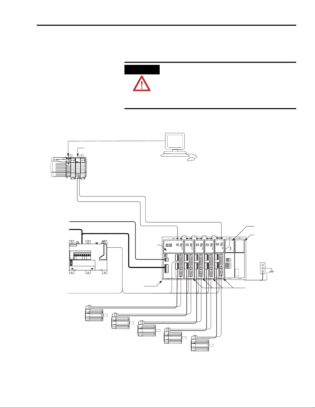
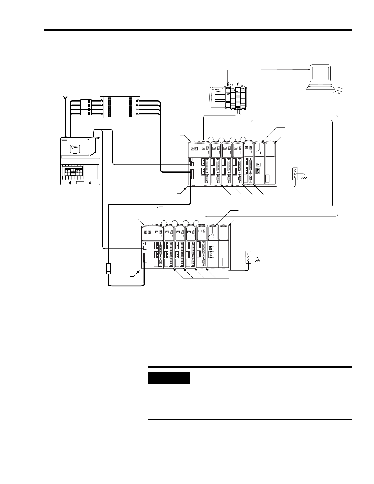
Typical Kinetix 2000 system installations include three-phase ac
configurations, with and without the line interface module (LIM), and dc
common bus configurations.
TM
SERCOS interface
OK
CP
Tx (rear)
Rx (front)
170...264V ac
Single-phase
Control Power
170...264V ac
Single-phase
or Three-phase
Input Power
Line
Interface
Module
(optional
component)
Line Filter built into this LIM (2094-AL09)
To Input Sensors
and Control String
WARNING
Typical Kinetix 2000 System Installation (with LIM)
ControlLogix Controller Programming Network
1756-M08SE SERCOS Interface Module
ControlLogix Chassis
SERCOS fiber-optic ring
Integrated
Module
Power
Rail
I/O Connections
Motor Feedback
Motor Power
To avoid personal injury due to electrical shock, place a slot
filler (catalog number 2093-PRF) in all empty slots on the power
rail.
Any power rail connector without a module installed will
disable the Kinetix 2000 three-phase power, however control
power is still present.
Workstation with RSLogix 5000 Software
Kinetix 2000 Multi-axis Servo Drive System
Axis
1 2
1 2 3
Shunt Module
and
Slot Filler Module
(Required when slot
is unoccupied by an
IAM, AM, or Shunt.)
Bonded Cabinet
Ground Bus
Axis Modules (4x)
MPL-, MPAI-, TL-, and Y-Series Motors
(MP-Series Low Inertia Motors Shown)
Publication 2093-UM001A-EN-P — March 2007
Page 14
14 Start
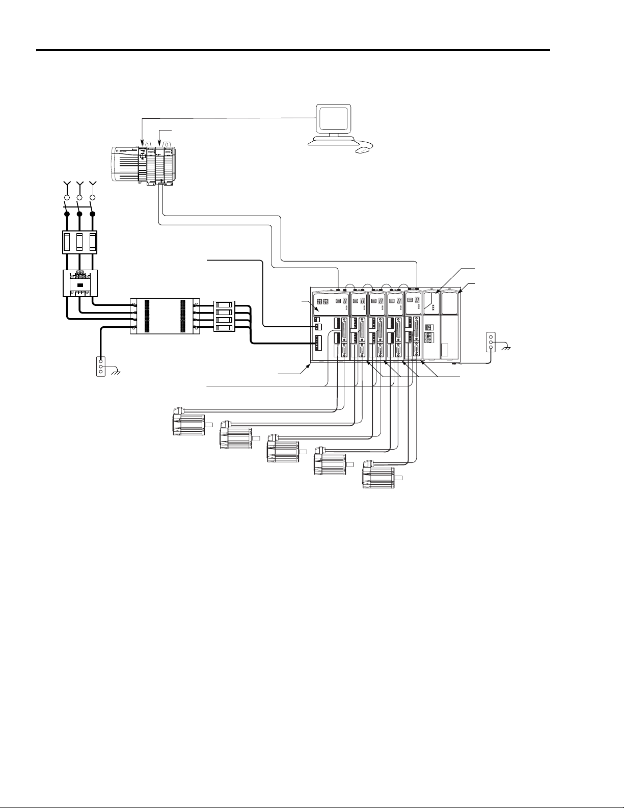
Typical Kinetix 2000 System Installation (without LIM)
170...264V ac
Single-phase
or Three-phase
Input Power
Bonded Cabinet
Ground Bus
Line
Disconnect
Device
Input
Fusing
Magnetic
Contactor
ControlLogix Controller Programming Network
1756-M08SE SERCOS Interface Module
TM
SERCOS interface
OK
CP
ControlLogix Chassis
Tx (rear)
Rx (front)
SERCOS fiber-optic ring
170...264V ac
Single-phase
Control Power
To Input Sensors
and Control String
Motor Feedback
Motor Power
Integrated
Axis
Module
Power
Rail
I/O Connections
Workstation with RSLogix 5000 Software
Kinetix 2000 Multi-axis Servo Drive System
1 2
1 2 3
Shunt Module
and
Slot Filler Module
(Required when slot
is unoccupied by an
IAM, AM, or Shunt.)
Bonded Cabinet
Ground Bus
Axis Modules (4x)
MPL-, MPAI-, TL-, and Y-Series Motors
(MP-Series Low Inertia Motors Shown)
Publication 2093-UM001A-EN-P — March 2007
Page 15
Typical DC Common Bus System Installation
Logix Controller Programming Network
Start 15
170...264V ac
Single-phase
or Three-phase
Input Power
Line Interface Module
(optional component)
2094-AL
170...264V ac
Single-phase
Control Power
xx
S
Common
Fusing
Bus
Line Filter
2090-XXLF-
170...264V ac
Single-phase
Control Power
Integrated
Module
Common Bus
Power
Rail
xxxx
Axis
(IAM)
Logix Chassis
(ControlLogix is shown)
Integrated
Axis
Module
(IAM)
Power
Rail
Kinetix 2000 Multi-axis Servo Drive System
SERCOS Fiber-optic Ring 2090-SC
SERCOS
Fiber-optic Ring
2090-SC
xxx-x
1 2
1 2 3
Logix SERCOS Interface Module
SERCOS interface
OK
CP
Tx (rear)
Rx (front)
xxx-x
1 2
1 2 3
Shunt Module (optional component)
Slot Filler Module
(Required when slot
is unoccupied by an
IAM, AM, or Shunt.)
Bonded Cabinet
Ground Bus
Axis Modules (4x)
Workstation with
RSLogix 5000 Software
Shunt Module
and
Slot Filler Module
(Required when slot
is unoccupied by an
IAM, AM, or Shunt.)
Bonded Cabinet
Ground Bus
Axis Modules (4x)
In the example above, a leader IAM is connected to a follower IAM via the dc
common bus. When planning your panel layout, you must calculate the total
bus capacitance of your dc common bus system to correctly size the leader
IAM to pre-charge the entire system. In RSLogix5000 software you identify
the common bus follower (disabling its shunt capabilities), and in doing so
require the leader IAM to control the entire common dc bus.
Refer to Appendix D, beginning on page 209, for more information.
IMPORTANT
If total bus capacitance of your system exceeds the leader IAM
pre-charge rating and input power is applied, the IAM seven-segment
Fault Status LED indicator will display error code E90 (pre-charge
timeout fault). To correct this condition, you must replace the leader
IAM with a larger module or decrease the total bus capacitance by
removing axis modules.
Publication 2093-UM001A-EN-P — March 2007
Page 16

16 Start
Catalog Number
Explanation
Kinetix 2000 drive catalog numbers and descriptions are listed in the table
below.
Kinetix 2000 Drive Catalog Numbers
Integrated Axis Modules (230V) Catalog Number
Kinetix 2000, IAM, 230V, 3 kW
Kinetix 2000, IAM, 230V, 3 kW
Kinetix 2000, IAM, 230V, 3 kW
Axis Modules (230V)
Kinetix 2000, AM, 230V, 1 A Inverter 2093-AMP1
Kinetix 2000, AM, 230V, 2 A Inverter 2093-AMP2
Kinetix 2000, AM, 230V, 3 A Inverter 2093-AMP5
Kinetix 2000, AM, 230V, 6 A Inverter 2093-AM01
Kinetix 2000, AM, 230V, 9 A Inverter 2093-AM02
Power Rails
Kinetix 2000, Single-Axis Power Rail 2093-PRS1
Kinetix 2000, Two-Axis Power Rail 2093-PRS2
Kinetix 2000, Three-Axis Power Rail 2093-PRS3
Kinetix 2000, Four-Axis Power Rail 2093-PRS4
Kinetix 2000, Five-Axis Power Rail 2093-PRS5
Kinetix 2000, Seven-Axis Power Rail 2093-PRS7
Kinetix 2000, Eight-Axis Power Rail with Shunt or Slot Filler 2093-PRS8S
Shunt Module
Kinetix 2000, SM, 230V, 50 W 2093-ASP06
Slot Filler
Kinetix 2000, SF, Power Rail Slot Filler 2093-PRF
(1)
Derated to 2 kW for single-phase operation.
(1)
Converter, 1 A Inverter
(1)
Converter, 2 A Inverter
(1)
Converter, 3 A Inverter
2093-AC05-MP1
2093-AC05-MP2
2093-AC05-MP5
Publication 2093-UM001A-EN-P — March 2007
Page 17

Start 17
Agency Compliance
If this product is installed within the European Union or EEC regions and has
the CE mark, the following regulations apply.
ATTENTION
Meeting CE requires a grounded system, and the method of grounding
the ac line filter and drive must match. Failure to do this renders the
filter ineffective and may cause damage to the filter.
For grounding examples, refer to Determining Your Type of Input
Power on page 63.
For more information on electrical noise reduction, refer to the System Design
for Control of Electrical Noise Reference Manual, publication GMC-RM001.
CE Requirements (System without LIM)
To meet CE requirements when your Kinetix 2000 system does not include
the line interface module (LIM), the following requirements apply.
• Install an ac line filter (2090-XXLF-xxxx) as close to the integrated axis
module (IAM) as possible.
• Use 2090-series motor power cables or use connector kits.
• Combined motor power cable length for all axes on the same dc bus
must not exceed 160 m (525 ft) with 230V systems. Drive-to-motor
power cables must not exceed 30 m (98.5 ft).
• Use 2090-series motor feedback cables or use connector kits and
properly terminate the feedback cable shield. Drive-to-motor feedback
cables must not exceed 30 m (98.5 ft).
• Install the Kinetix 2000 system inside an enclosure. Run input power
wiring in conduit (grounded to the enclosure) outside of the enclosure.
Separate signal and power cables.
Wiring instructions are available in Chapter 5 of this publication. Product
catalog numbers are listed in the Kinetix Motion Control Selection Guide,
publication GMC-SG001.
Publication 2093-UM001A-EN-P — March 2007
Page 18

18 Start
CE Requirements (System with LIM)
To meet CE requirements when your Kinetix 2000 system includes the line
interface module (LIM), follow all the requirements as stated in CE
Requirements (System without LIM), and these additional requirements as
they apply to the ac line filter.
• Install the LIM (2094-AL09) as close to the integrated axis module
(IAM) as possible.
• Install the LIM (2094-ALxxS, -or -XL75S-Cx) with the line filter
(2090-XXLF-xxxx) as close to the IAM as possible.
When the LIM (2094-ALxxS, or -XL75S-Cx) supports two IAMs, each
IAM requires an ac line filter installed as close to the IAM as possible.
Publication 2093-UM001A-EN-P — March 2007
Page 19
Chapter
Planning the Kinetix 2000 Drive System
Installation
2
Introduction
System Design Guidelines
This chapter describes system installation guidelines used in preparation for
mounting your Kinetix 2000 drive components.
Topic Page
System Design Guidelines 19
Minimizing Electrical Noise 26
ATTENTION
Use the information in this section when designing your enclosure and
planning to mount your system components on the panel.
Plan the installation of your system so that you can perform all cutting,
drilling, tapping, and welding with the system removed from the
enclosure. Because the system is of the open type construction, be
careful to keep any metal debris from falling into it. Metal debris or
other foreign matter can become lodged in the circuitry, which can
result in damage to components.
System Mounting Requirements
The following is general information for selecting an enclosure and mounting
your system components within the panel.
• In order to comply with UL and CE requirements, the Kinetix 2000
system must be enclosed in a grounded conductive enclosure offering
protection as defined in standard EN 60529 (IEC 529) to IP55 such
that they are not accessible to an operator or unskilled person. A
NEMA 4X enclosure exceeds these requirements providing protection
to IP66.
• The panel you install inside the enclosure for mounting your system
components must be on a flat, rigid, vertical surface that won’t be
subjected to shock, vibration, moisture, oil mist, dust, or corrosive
vapors.
19 Publication 2093-UM001A-EN-P — March 2007
Page 20

20 Planning the Kinetix 2000 Drive System Installation
• Size the drive enclosure so as not to exceed the maximum ambient
temperature rating. Consider heat dissipation specifications for all drive
components and other devices that radiate heat into the cabinet.
• Segregate input power wiring and motor power cables from control
wiring and motor feedback cables as they leave the drive. Maintain this
separation throughout the wire run.
• Use Rockwell Automation/Allen-Bradley shielded cable for power
wiring and provide a grounded 360° clamp termination to the enclosure
wall.
• Use high-frequency (HF) bonding techniques to connect the modules,
enclosure, machine frame, and motor housing, and to provide a
low-impedance return path for high-frequency (HF) energy and reduce
electrical noise.
Refer to the System Design for Control of Electrical Noise Reference
Manual, publication GMC-RM001, to better understand the concept of
electrical noise reduction.
IMPORTANT
To improve the bond between the power rail and subpanel,
construct your subpanel out of zinc plated (paint-free) steel.
Transformer Selection
The integrated axis module (IAM) does not require an isolation transformer
for three-phase input power. However, a transformer may be required to
match the voltage requirements of the controller to the available service.
To size a transformer for the main ac power inputs, refer to the Circuit
Breaker/Fuse Specifications on page 157 and Transformer Specifications for
Control Power Input on page 159. Multiple power rails in a single cabinet
require additional transformers or additional transformer capacity.
IMPORTANT
IMPORTANT
If using an autotransformer, make sure that the phase to neutral/
ground voltages do not exceed the input voltage ratings of the drive.
Use a form factor of 1.5 for three-phase power (where form factor is
used to compensate for transformer, drive module and motor losses,
and to account for utilization in the intermittent operating area of the
torque speed curve).
Publication 2093-UM001A-EN-P — March 2007
Example: Sizing a transformer to the voltage requirements of a
2093-AC05-MP5 Integrated Axis Module:
2093-AC05-MP5 = 3 kW continuous x 1.5 = 4.5 KVA transformer
Page 21

Planning the Kinetix 2000 Drive System Installation 21
Circuit Breaker/Fuse Selection
The Kinetix 2000 system utilizes internal short circuit output protection and is
suitable for use on a circuit capable of delivering up to 100,000 Amperes, when
protected by class CC, J, L, and R fuses. Circuit breakers with adequate
widthstand and interrupt ratings, as defined in NEC 2002, article 110.9 and
110.10, are also permitted.
The Bulletin 140M product may be another acceptable means of protection
with the Kinetix 2000 system. As with fuses and circuit breakers, you must
make sure that the selected components are properly coordinated and meet
applicable codes. When applying the 140M product, evaluation of the short
circuit available current is critical and must be kept below the short circuit
rating of the 140M product. As long as you do this review, and the conditions
for use are met, the 140M product is appropriate for use with the Kinetix 2000
system.
The line interface module (LIM) contains different circuit protection based on
type:
• 2094-AL09 contains supplementary protection device, 1492-CB (UL
508), and therefore class CC or J fuses with 5kA SCCR must be used on
the line side of the 2094-AL09 LIM.
• 2094-AL15S, 2094-AL25S, 2094-AL50S, 2094-AL75S, and 2094-XL75S
contain Bulletin 140U (UL 489) motor branch circuit protection.
Overcurrent protection must be adequately coordinated per NEC 2002, article
240.
In most cases, fuses selected to match the drive input current rating will meet
the NEC requirements and provide the full drive capabilities. Dual element,
time delay (slow acting) fuses should be used to avoid nuisance trips during the
inrush current of power initialization.
Refer to Circuit Breaker/Fuse Specifications on page 157 for recommended
circuit breakers and fuses.
Refer to Power Specifications on page 154 for input current and inrush current
specifications for your IAM.
Enclosure Selection
The following example is provided to assist you in sizing an enclosure for your
Kinetix 2000 system. The example system consists of the following
components:
• Six-axis Kinetix 2000 servo drive system
• Line Interface Module (LIM)
• ControlLogix chassis and modules (controller)
Size the Kinetix 2000 servo drive and LIM and use the results to predict the
amount of heat dissipated into the enclosure. You will also need heat
Publication 2093-UM001A-EN-P — March 2007
Page 22

22 Planning the Kinetix 2000 Drive System Installation
dissipation data from other equipment inside the enclosure (such as
ControlLogix controller). Once the total amount of heat dissipation (in Watts)
is known, the minimum enclosure size can be calculated.
Kinetix 2000 System Heat Dissipation Example
Enclosure Component Description
2093-AC09-M02
2093-AM02 Axis module (AM), 230V, 9 A 60% 67.3
2093-AM02 Axis module (AM), 230V, 9 A 60% 67.3
2093-AM01 Axis module (AM),230V, 6 A 40% 46.7
2093-AM01 Axis module (AM), 230V, 6 A 40% 46.7
2093-AM01 Axis module (AM), 230V, 6 A 20% 46.7
2093-AL09 Line interface module (LIM), 230V, 6 kW, 6 A; 24V dc 3 A 100% 72.0
2093-PR6 Power rail, 230V, 6 axis N/A 0.0
Total Kinetix 2000 system Wattage
(1)
To determine heat dissipation specifications for the Kinetix 2000 components, refer to Power Dissipation Specifications on page 160.
Integrated axis module (IAM),
230V, three-phase
Loading
(1)
Heat Dissipation
Watts
3 kW (converter section) 20% 7.0
1 A (inverter section) 40% 33.6
387.3
(1)
ControlLogix System Heat Dissipation Example
Enclosure
Component
Description
1756-M08SE 8-axis SERCOS interface module 3.2 0
1756-L55M12 5555 ControlLogix processor 4.5 0
1756-IB16D 16 -point input module 0.84 5.8
1756-OB16D 16 -point output module 4.64 3.3
1756-ENBT Ethernet communications module 4.0 0
Backplane total
1756-PB72 24V dc ControlLogix power supply N/A
1756-A7 7-slot mounting chassis N/A N/A
Total ControlLogix system Wattage 34.1
(1)
For ControlLogix module specifications, refer to the ControlLogix Selection Guide, publication 1756-SG001.
(2)
Real power heat dissipation is determined by applying the backplane power load (17.18 W) to the graph below.
Backplane Power
(1)
Watts
Load
(2)
17.18
Heat Dissipation
Watts
N/A
25
ControlLogix Real Power
1756-P B72
1756-P B75
Backplane dc
Power Load
(Watts)
75
60
45
30
15
0
0 20 40 60 8 0 100
Real Power (Watts)
(1)
(2)
Publication 2093-UM001A-EN-P — March 2007
Page 23

Planning the Kinetix 2000 Drive System Installation 23
For backplane power loading requirements of other ControlLogix power
supplies, refer to the ControlLogix Selection Guide, publication 1756-SG001.
In this example, the amount of power dissipated inside the cabinet is the sum
of the Kinetix 2000 system value (387 W) and the ControlLogix system value
(34 W) for a total of 421 W.
With no active method of heat dissipation (such as fans or air conditioning)
either of the following approximate equations can be used.
Metric Standard English
0.38Q
------------------------
A
=
1.8T 1.1–
Where T is temperature difference between
inside air and outside ambient (°C), Q is heat
generated in enclosure (Watts), and A is
enclosure surface area (m
of all six sides of an enclosure is calculated as
A = 2dw + 2dh + 2wh A = (2dw + 2dh + 2wh) / 144
Where d (depth), w (width), and h (height) are in
meters.
2
). The exterior surface
Where T is temperature difference between
inside air and outside ambient (°F), Q is heat
generated in enclosure (Watts), and A is
enclosure surface area (ft²). The exterior surface
of all six sides of an enclosure is calculated as
Where d (depth), w (width), and h (height) are in
inches.
4.08Q
----------------
A
=
T 1.1–
The maximum ambient rating of the Kinetix 2000 system is 50 °C (122 °F)
and if the maximum environmental temperature is 30 °C (86 °F) then Q=606
and T=20 in the equation below.
0.38 421()
--------------------------------
A
1.8 20()1.1–
≈=
In this example, the enclosure must have an exterior surface of 4.58 meters
4.58m
2
2
. If
any portion of the enclosure is not able to transfer heat, it should not be
included in the calculation.
Since the minimum cabinet depth to house the 230V drive (selected for this
example) is 200 mm (7.9 in.), then the cabinet needs to be approximately
2000 mm (78.7 in.) high x 1000 mm (39.4 in.) wide x 200 mm (7.9 in.) deep.
2 x (0.2 x 1.0) + 2 x (0.2 x 1.0) + 2 x (1.0 x 2.0) = 4.8 m2
7.9 x 39.4) + 2 x (7.9 x 39.4) + 2 x (39.4 x 78.7) = 48 ft.
2 x (
2
Because this cabinet size is considerably larger than what is necessary to house
the system components, it may be more efficient to provide a means of cooling
in a smaller cabinet. Contact your cabinet manufacturer for options available to
cool your cabinet.
Publication 2093-UM001A-EN-P — March 2007
Page 24
24 Planning the Kinetix 2000 Drive System Installation
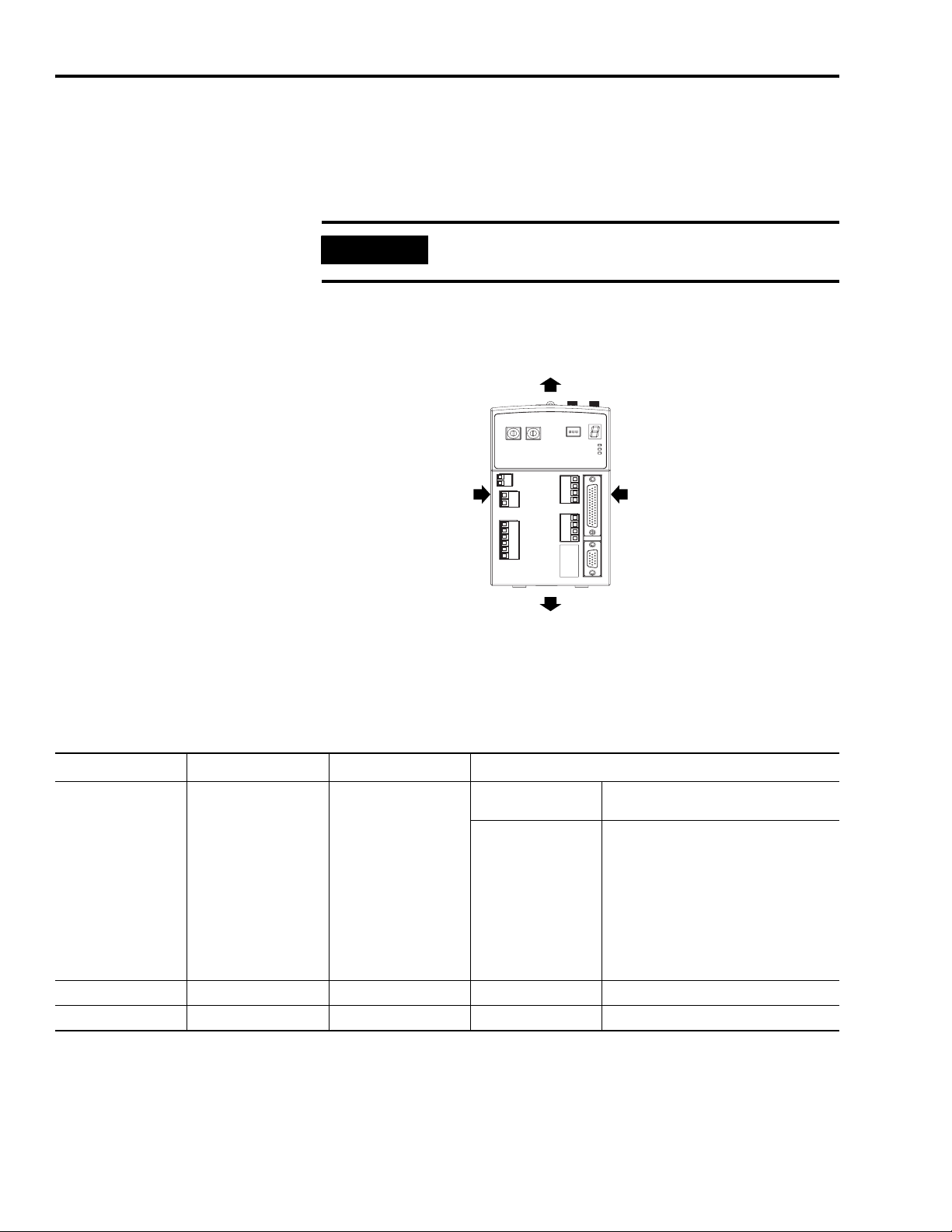
Minimum Clearance Requirements
This section provides information to assist you in sizing your cabinet and
positioning your Kinetix 2000 system components.
IMPORTANT
Mount the module in an upright position. Do not mount the module on
its side.
Minimum Clearance Requirements
Clearance above
for airflow and installation.
Integrated Axis Module (IAM),
catalog number 2093-AC05-MP1,
is shown mounted on power rail
as the first module.
Clearance left of the
module is not required.
(1)
The power rail, catalog number 2093-PRSxx, does not extend left of the first module or right of the last module.
(1)
Clearance below
for airflow and installation.
Clearance right of the
module is not required.
(1)
Minimum Clearance Dimensions
Cat. No. Clearance Above, Min Clearance Below, Min
2093-AC05-MP1,
2093-AC05-MP2,
2093-AC05-MP5.
2093-AMP1,
2093-AMP2,
50.8 mm (2.0 in.) 50.8 mm (2.0 in.)
2093-AMP5,
2093-AM01,
2093-AM02
2093-ASP06 305 mm (12.0 in.) 50.8 mm (2.0 in.) 200 mm (7.9 in.)
2093-PRF None None None
(1)
Additional clearance required to accommodate cable bend restrictions.
Cabinet Depth Clearance, Min
200 mm (7.9 in.)
235 mm (9.25 in.)
(1)
If 15-pin connector kit, catalog number
2090-K2CK-D15M, is attached.
44-pin connector kit options include:
• 2090-U3BK-D44xx connector kit
(containing a 2090-U3BK-D44 terminal
block and 2090-U3BK-D44xx cable)
• 2090-U3BK-D44 terminal block and
custom-built cable.
• 2090-U3BK-D44 terminal block and flying
lead cable.
Publication 2093-UM001A-EN-P — March 2007
Page 25

Planning the Kinetix 2000 Drive System Installation 25
IMPORTANT
Although clearance left and right of the power rail is not necessary for
ventilation, additional clearance is required when mounted adjacent
to noise sensitive equipment or clean wireways.
Refer to page 160 for power dissipation specifications.
Publication 2093-UM001A-EN-P — March 2007
Page 26

26 Planning the Kinetix 2000 Drive System Installation
Minimizing Electrical
Noise
This section outlines best practices which minimize the possibility of
noise-related failures as they apply specifically to Kinetix 2000 system
installations.
For more information on the concept of high-frequency (HF) bonding, the
ground plane principle, and electrical noise reduction, refer to the System
Design for Control of Electrical Noise Reference Manual, publication
GMC-RM001.
Bonding Modules
Bonding is the practice of connecting metal chassis, assemblies, frames,
shields, and enclosures to reduce the effects of electromagnetic interference
(EMI).
Unless specified, most paints are not conductive and act as insulators. To
achieve a good bond between power rail and the subpanel, surfaces need to be
paint-free or plated. Bonding metal surfaces creates a low-impedance return
path for high-frequency energy.
IMPORTANT
To improve the bond between the power rail and subpanel, construct
your subpanel out of zinc plated (paint-free) steel.
Improper bonding blocks the direct return path and results in high-frequency
energy traveling elsewhere in the cabinet. Excessive high-frequency energy can
effect the operation of other microprocessor controlled equipment.
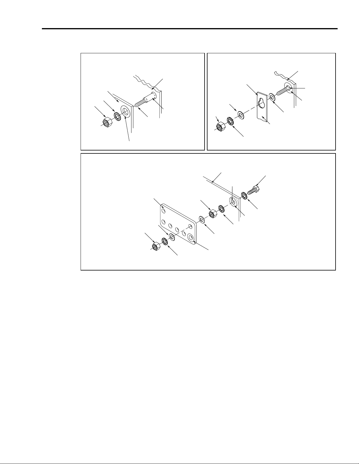
The illustrations that follow show details of recommended bonding practices
for painted panels, enclosures, and mounting brackets.
Publication 2093-UM001A-EN-P — March 2007
Page 27
Planning the Kinetix 2000 Drive System Installation 27
Recommended Bonding Practices for Painted Panels
Stud-mounting the Subpanel
to the Enclosure Back Wall
Back Wall of
Enclosure
Subpanel Welded Stud
Star Washer
Nut
Use a wire brush to remove paint from
threads to maximize ground
connection.
Use plated panels or scrape paint on
front of panel.
Welded Stud
Mounting Bracket or
Flat Washer
Nut
Stud-mounting a Ground Bus
or Chassis to the Subpanel
Ground Bus
Flat Washer
If the mounting bracket is coated
with a non-conductive material
(anodized or painted), scrape the
Star Washer
material around the mounting hole.
Subpanel
Scrape Paint
Bolt-mounting a Ground Bus or Chassis to the Back-panel
Ground Bus or
Mounting Bracket
Flat Washer
Nut
Subpanel
Tapped Hole
Nut
Scrape paint on both sides of
panel and use star washers.
Star Washer
Flat Washer
Bolt
Star Washer
If the mounting bracket is coated
Star Washer
with a non-conductive material
(anodized or painted), scrape the
material around the mounting hole.
Bonding Multiple Subpanels
Bonding multiple subpanels creates a common low impedance exit path for
the high frequency energy inside the cabinet. Subpanels that are not bonded
together may not share a common low impedance path. This difference in
impedance may affect networks and other devices that span multiple panels.
Publication 2093-UM001A-EN-P — March 2007
Page 28
28 Planning the Kinetix 2000 Drive System Installation
Multiple Subpanels and Cabinet Recommendations
Bond the top and bottom of each subpanel to the cabinet using
25.4 mm (1.0 in.) by 6.35 mm (0.25 in.) wire braid.
Cabinet ground bus
bonded to the subpanel.
Scrape the paint around each fastener to
maximize metal to metal contact.
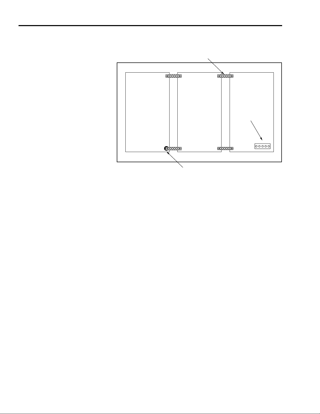
Establishing Noise Zones
Observe the following guidelines when a LIM (2094-AL09) is used in the
Kinetix 2000 system and mounted left of the IAM:
This layout is preferred due to the reduced size of the very dirty zone.
• The clean zone (C) is to the right and beneath the Kinetix 2000 system
(grey wireway).
• The dirty zone (D) is to the left and above the Kinetix 2000 system, and
above and below the LIM (black wireway).
• The very dirty zone (VD) is limited to where the LIM VAC output
jumpers over to the IAM. Shielded cable is required only if the very dirty
cables enter a wireway.
• The SERCOS fiber-optic cables are immune to electrical noise.
Publication 2093-UM001A-EN-P — March 2007
Page 29
Planning the Kinetix 2000 Drive System Installation 29
Establishing Noise Zones (LIM mounted left of IAM)
Dirty Wireway
D
D
2094-AL09 Line Interface Module
Line Filter built into this LIM
(1)
If IAM/AM I/O cable contains (dirty) relay wires, route cable with LIM I/O cable in dirty wireway.
(2)
When space does not permit the 150 mm (6.0 in.) segregation, use a grounded steel shield instead. For
examples, refer to Chapter 4 of the System Design for Control of Electrical Noise Reference Manual,
publication GMC-RM001.
Very Dirty LIM/IAM Connections
Segregated (not in wireway)
VD
DD
Route 24V dc
I/O Shielded
C
C
Route Encoder/Analog/Registration
Shielded Cables
Clean Wireway
Fiber-optic Cable
No Sensitive
Equipment
within 150 mm
Kinetix 2000
System
(1)
I/O and
Feedback Cables
(2)
Publication 2093-UM001A-EN-P — March 2007
Page 30
30 Planning the Kinetix 2000 Drive System Installation
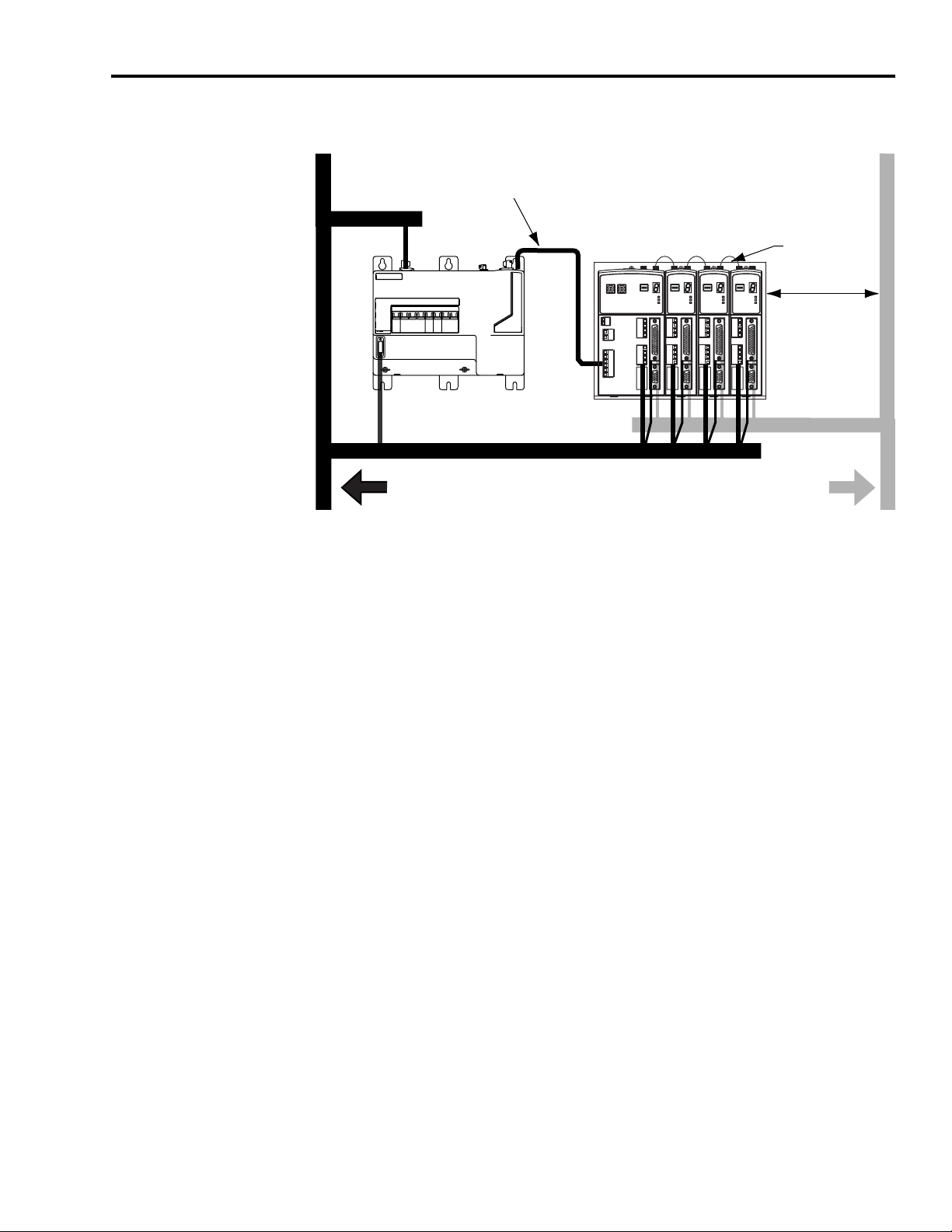
Observe the following guidelines when a LIM (2094-ALxxS, or
2094-XL75S-Cx) is used in the Kinetix 2000 system and mounted left of the
IAM with the ac (EMC) line filter mounted above the LIM:
• The clean zone (C) is to the left and below the Kinetix 2000 system
(grey wireway).
• The dirty zone (D) is to the right and above the Kinetix 2000 system,
and above and below the LIM (black wireway).
• The very dirty zone (VD) is from the filter output to IAM. Shielded
cable is required on the EMC filter (load side) and the braided shield
attached to the clamp provided.
• The SERCOS fiber-optic cables are immune to electrical noise.
Establishing Noise Zones (LIM mounted right of IAM)
Very Dirty Filter/IAM Connections
Clean Wireway Dirty Wireway
Segregated (Not in Wireway)
No Sensitive
Equipment
Within 150 mm
I/O and Feedback Cables
C
Route Encoder/Analog/Registration
Shielded Cables
(1)
(2)
VD D
V ac Line
Line Filter
Fiber-optic Cable
(2)
VD
(1)
D
If IAM/AM I/O cable contains (dirty) relay wires, route cable with LIM I/O cable in dirty wireway.
When space does not permit the 150 mm (6.0 in.) segregation, use a grounded steel shield instead. For
examples, refer to Chapter 4 of the System Design for Control of Electrical Noise Reference Manual,
publication GMC-RM001.
C
V ac LOAD
D
MAIN VAC
Kinetix 2000
Drives
Line Interface Module
Route Motor Power and
24V dc I/O Shielded Cables
D
D
D
Publication 2093-UM001A-EN-P — March 2007
Page 31

Planning the Kinetix 2000 Drive System Installation 31
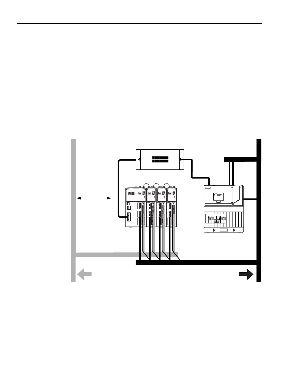
Observe the following guidelines when a LIM (2094-AL09) is used in the
Kinetix 2000 system and mounted above the IAM:
• The clean zone (C) is to the right and beneath the Kinetix 2000 system
(grey wireway).
• The dirty zone (D) is to the left and above the Kinetix 2000 system, and
above and below the LIM (black wireway).
• The LIM VAC output is very dirty (VD). Use shielded cable with a braid
clamp attached at both ends of the cable to reduce the rating to dirty
(D).
• The SERCOS fiber-optic cables are immune to electrical noise.
Establishing Noise Zones (LIM mounted above IAM)
Dirty Wireway
D
VD
D
Line Interface Module
Clean Wireway
V ac LINEV ac LOAD
Very Dirty LIM/IAM
connections must be
shielded with braid
clamp at both ends.
No Sensitive
Within 150 mm
Kinetix 2000
Drives
C
I/O and Feedback Cables
Fiber-optic Cable
Equipment
(1)
(3)
C
(2)
Power Cables
Route Encoder/Analog/Registration
Route Motor Power and
24V dc I/O Shielded Cables
(1)
For examples of shield clamp attachment, refer to the System Design for Control of Electrical Noise Reference
Manual, publication GMC-RM001.
(2)
If IAM/AM I/O cable contains (dirty) relay wires, route cable in dirty wireway.
(3)
When space does not permit the 150 mm (6.0 in.) segregation, use a grounded steel shield instead. For
examples, refer to Chapter 4 of the System Design for Control of Electrical Noise Reference Manual,
publication GMC-RM001.
Shielded Cables
Publication 2093-UM001A-EN-P — March 2007
Page 32

32 Planning the Kinetix 2000 Drive System Installation
Observe the following guidelines when a LIM (2094-ALxxS, or
2094-XL75S-Cx) is used in a dc common bus configuration and the follower
IAM is mounted below the leader IAM:
• The very dirty zone (VD) is from the filter output to the Leader IAM,
and the entire length of the dc common bus cable. Shielded cable is
required on the EMC filter (load side) and the braided shield attached to
the clamp provided.
• Keep the dc common bus cable (very dirty) segregated from all other
cables (not in a wireway).
• The clean zone (C) is to the right and below the Kinetix 2000 system
(grey wireway).
• The dirty zone (D) is to the left of the Kinetix 2000 system, and above
and below the LIM (black wireway).
• The SERCOS fiber-optic cables are immune to electrical noise.
Establishing Noise Zones (dc common bus)
Dirty Wireway Clean Wireway
170...264V ac
D
Single-phase
D
Line Filter
Vac Line, AUX Vac Output, 24V
V ac Load
V ac Line
DD D
Line Interface Module
D
Common Bus
Segregated
(not in wireway)
170...264V ac
D
Auxiliary Power
Route 24V dc I/O
shielded cable
170...264V ac
Three-phase
Main Power
Single-phase
(1)
VD
C
C
VD
VD
(1)
VD
(1)
(1)
Auxiliary Power
D
equipment within
150 mm (6.0 in.)
Kinetix 2000
System
(leader IAM)
Feedback CablesMotor Power Cables
equipment within
150 mm (6.0 in.)
Kinetix 2000
System
(follower IAM)
Feedback CablesMotor Power Cables
Route encoder/analog/registration
shielded cable
Fiber-optic cables
No sensitive
(2)
I/O and
Fiber-optic cables
No sensitive
(2)
I/O and
(3)
C
(3)
C
Publication 2093-UM001A-EN-P — March 2007
Page 33

Planning the Kinetix 2000 Drive System Installation 33
(1)
Very Dirty connections must be shielded with braid clamp at both ends.For examples of shield clamp
attachment, System Design for Control of Electrical Noise Reference Manual, publication GMC-RM001,
publication System Design for Control of Electrical Noise Reference Manual, publication GMC-RM001.
(2)
If IAM/AM I/O cable contains (dirty) relay wires, route cable with LIM I/O cable in dirty wireway.
(3)
When space does not permit the 150 mm (6.0 in.) segregation, use a grounded steel shield instead. For
examples, refer to Chapter 4 of the System Design for Control of Electrical Noise Reference Manual,
publication GMC-RM001.
Observe the following guidelines when individual input power components
are used in the Kinetix 2000 system and the LIM (2094-xLxx or
2094-xLxxS-xx) is not used:
• The clean zone (C) is beneath the Kinetix 2000 system and includes the
I/O wiring, feedback cable, and dc filter (grey wireway).
• The dirty zone (D) is above the Kinetix 2000 system (black wireway)
and includes the circuit breakers, transformer, 24V dc power supply,
contactors, ac line filter, and motor power cables.
• The very dirty zone (VD) is limited to where the ac line (EMC) filter
VAC output jumpers over to the IAM. Shielded cable is required only if
the very dirty cables enter a wireway.
• The SERCOS fiber-optic cables are immune to electrical noise.
Establishing Noise Zones (No LIM)
Dirty Wireway
Very dirty EMC filter/IAM connection
D
segregated (not in wireway)
D
(5)
VD
AC
Line Filter
Kinetix 2000
System
(1)
Circuit
Breaker
XFMR
24V Motor
Brake PS
(4)
(3)
DC
Filter
Contactors
I/O and Feedback Cables
C
D
Route Motor Power and
24 V dc I/O Shielded Cables
(1)
If IAM/AM I/O cable contains (dirty) relay wires, route cable in dirty wireway.
(2)
When space to the right of the IAM does not permit 150 mm (6.0 in.) segregation, use a grounded steel shield
instead. For examples, refer to Chapter 4 of the System Design for Control of Electrical Noise Reference
Manual, publication GMC-RM001.
(3)
This is a clean 24V dc available for any device that may require it. The 24V enters the clean wireway and exits
to the right.
(4)
This is a dirty 24V dc available for motor brakes and contactors. The 24V enters the dirty wireway and exits to
the left.
Route Encoder/Analog/Registration
Shielded Cables
Clean Wireway
(2)
(2)
C
D
Publication 2093-UM001A-EN-P — March 2007
Page 34

34 Planning the Kinetix 2000 Drive System Installation
Observe the following guidelines when installing a 1756-MxxSE SERCOS or
other Logix interface modules:
• The clean zone (C) is beneath the less noisy modules, such as I/O,
encoder, registration (grey wireway).
• The dirty zone (D) is above and below the power supply and noisy
modules (black wireway).
• The SERCOS fiber-optic cables are immune to electrical noise.
Establishing Noise Zones (ControlLogix)
Dirty Wireway
D
EMC
Filter
Very-dirty
filter/power supply
connections
segregated (not in
(1)
Segregate VD wiring from D and C wiring, or use shielded cable (shield bonded to both panel at both ends)
which then becomes category D.
Route dirty wireways directly above the ControlLogix rack
D
VD
(1)
(shielded by the ControlLogix chassis)
Spare Slot(s)
D
Dirty I/O
(24V dc I/O, AC I/O)
Clean I/O
(Analog, Encoder
Registration)
Clean Wireway
C
Cable Categories for Kinetix 2000 Systems
Wire/Cable Connector
CTRL 1 and 2 CPD X
DC-/DC+ (unshielded cable)
L1, L2, L3 (shielded cable) X X
L1, L2, L3 (unshielded cable) X
CONT EN- and CONT EN+ (M1 contactor) CED X
DPI DPI X X
Publication 2093-UM001A-EN-P — March 2007
The table below indicates the zoning requirements of cables connecting to the
Kinetix 2000 drive components.
Integrated Axis Module (Converter Side)
Zone Method
IPD
Ver y
Dirty
Dirty Clean
XX
Ferrite
Sleeve
Shielded
Cable
Page 35

Planning the Kinetix 2000 Drive System Installation 35
Integrated Axis Module or Axis Module (Inverter Side)
Zone Method
Wire/Cable Connector
U, V, W (motor power) MP X X
MBRK-, MBRK+ (motor brake)
COM, PWR (24V dc), filtered
COM, PWR (24V dc), unfiltered
(1)
(2)
BC
Motor feedback MF X X
Auxiliary feedback AF X X
Registration outputs
IOD
Others X
Fiber-optic Rx and Tx No Restrictions
(1)
This is a clean 24V dc available for any device that may require it.
(2)
This is a dirty 24V dc available for motor brakes and contactors.
Ver y
Dirty
Dirty Clean
X
X
X
XX
Ferrite
Sleeve
Shielded
Cable
Line Interface Module
Zone Method
Wire/Cable Connector
V ac line (main input) IPL X
230V ac input APL X
V ac load (shielded option)
V ac load (unshielded option) X
OPL
Control power output CPL X
MBRK PWR, MBRK COM P1L/PSL X
Status I/O IOL X
Auxiliary 230V ac P2L X
Ver y
Dirty
Dirty Clean
Ferrite
Sleeve
Shielded
Cable
XX
Publication 2093-UM001A-EN-P — March 2007
Page 36

36 Planning the Kinetix 2000 Drive System Installation
Noise Reduction Guidelines for Drive Accessories
When mounting an ac (EMC) line filter refer to the sections below for
guidelines designed to reduce system failures caused by excessive electrical
noise.
Line Filters, ac
Observe the following guidelines when mounting your ac (EMC) line filter
(refer to the figure on page 33 for an example):
• Mount the line filter on the same panel as the Kinetix 2000 drive and as
close to the power rail as possible.
• Good HF bonding to the panel is critical. For painted panels, refer to
the examples on page 27.
• Segregate input and output wiring as far as possible.
IMPORTANT
CE test certification applies only to ac line filter and single power rail.
Sharing a line filter with multiple power rails may perform
satisfactorily, but the user takes legal responsibility.
Motor Brake and Thermal Switch
The thermal switch and brake are mounted inside the motor, but how you
connect to the axis module depends on the motor series.
Refer to Wiring the Motor Brake (BC) Connector on page 89 for wiring
guidelines. Refer to Axis Module/Motor Wiring Examples beginning on page
178 for the interconnect diagram of your drive/motor combination.
Publication 2093-UM001A-EN-P — March 2007
Page 37

Chapter
Mounting the Kinetix 2000 Drive System
3
Introduction
This chapter provides the system installation procedures for mounting your
Kinetix 2000 drive components to the panel.
Topic Page
Installing the 2093 Power Rail 37
Determining Mounting Order 38
Mount the Modules 40
Mounting the Line Interface Module 41
Segregating Power and Logic Wires 42
The procedures in this chapter assume you have prepared your panel and
understand how to bond your system. For installation instructions regarding
equipment and accessories not included here, refer to the instructions that
came with those products.
WARNING
To avoid hazard of electrical shock, perform all mounting and wiring of
IAM, AM, SM, SF, LIM, or power rail prior to applying power. Once
power is applied, connector terminals may have voltage present even
when not in use.
ATTENTION
Installing the 2093 Power
Rail
37 Publication 2093-UM001A-EN-P — March 2007
The Kinetix 2000 power rail comes in configurations that support one
integrated axis module (IAM), up to seven additional axis modules (AM), and
a shunt module (SM). A slot filler (SF) must occupy any open position.
Plan the installation of your system so that you can perform all cutting,
drilling, tapping, and welding with the system removed from the
enclosure. Because the system is of the open type construction, be
careful to keep any metal debris from falling into it. Metal debris or
other foreign matter can become lodged in the circuitry, which can
result in damage to components.
Page 38

38 Mounting the Kinetix 2000 Drive System
Refer to the Kinetix 2000 Power Rail Installation Instructions, publication
2093-IN004, when installing your power rail.
Determining Mounting
Order
Highest
Integrated Axis Module
2093-AC05-MP5
ATTENTION
To avoid damage to the power rail during installation, do not remove
the protective boots until the module for each slot is ready for
mounting.
Mount IAM, AM, and SM modules in the order (left to right) shown in the
figure. A slot filler (SF) must occupy any unoccupied slots. Mount axis
modules according to power utilization (highest to lowest) from left to right
starting with the highest power utilization. If power utilization is unknown,
position axis modules (highest to lowest) from left to right based on Amp
rating.
Module Mounting Order
Power Utilization or Amp Rating Lowest
Axis Module
2093-AM01
Axis Module
2093-AMP2
Axis Module
2093-AMP2
Shunt Module
2093-ASP06
Slot Filler Module
2093-PRF
Publication 2093-UM001A-EN-P — March 2007
Seven-axis Power Rail Module 2093-PRS7
Page 39

Mounting the Kinetix 2000 Drive System 39
IMPORTANT
Position the integrated axis module (IAM) in the leftmost slot of the
power rail. Position your axis modules (AM), shunt module (SM), and
slot fillers (SF) to the right of the IAM.
Install axis modules according to power utilization (highest to lowest)
from left to right. The AM requiring the highest power utilization
should be on the left.
Install the shunt module to the right of the last AM. Only slot fillers
may be installed to the right of the shunt module.
Do not mount a shunt module on the power rail of a follower IAM.
Common-bus follower IAMs will disable any rail mounted or external
shunt modules.
SHOCK HAZARD
To avoid personal injury due to electrical shock, place a slot filler
module in all empty slots on the power rail.
A unoccupied power rail connector will disable the Kinetix 2000
system, however control power will still be present.
2093-PRS8S Module Configuration
The 2093-PRS8S power rail is unique in that it has nine slots, but can
accommodate only eight axis modules (IAM and AMs). The last slot must be
occupied by a shunt module (SM) or a slot filler (SF), or a double-wide axis
module (AM) occupying both slots 7 and 8.
The table shows valid 2093-PRS8S power rail configurations with the
maximum number of axis modules. Configurations with fewer axis modules
are valid when the slots to the right of the axis modules (IAM and AM) are
occupied by a single shunt module (SM), or slot filler (SF) modules as
described in Determining Mounting Order on page 38.
Valid 2093-PRS8S Module Positions
Slot Number
0 1 2 3 4 5 6 7 8
IAM
IAM AM AM AM AM
IAM AM AM AM AM AM
IAM AM AM AM AM AM AM
IAM AM AM AM AM AM AM AM
(1)
Axis modules (AM) are available in double-width (2093-AM01 and 2093-AM02) and single-width (2093-AMP1,
2093-AMP2, and 2093-AMP5).
(2)
Only the following modules may occupy slot 8 in the 2093-PRS8S power rail: a shunt module (2093-ASP06), a
slot filler (2093-PRF), or a double-width axis module (2093-AM01 or 2093-AM02) occupying both slots 7 and 8.
Refer to the Node Addressing Example 4 on page 108 for information on slot assignment and logical addressing
of an axis module in slot 8.
AM
(1)
AM AM
AM
(2)
SM or SF
SM or SF
SM or SF
SM or SF
(2)
(2)
(2)
(2)
Publication 2093-UM001A-EN-P — March 2007
Page 40

40 Mounting the Kinetix 2000 Drive System
Mount the Modules
IMPORTANT
Invalid module positioning on a 2093-PRS8S power rail may result in
incorrect operation.
Follow these steps to mount the IAM, AM, SM, and SF modules. All modules
mount to the power rail using the same technique.
1. Determine the next available slot and module for mounting.
IMPORTANT
ATTENTION
The IAM must be positioned in the leftmost slot of the power
rail. Position your axis modules, shunt module, and slot fillers to
the right of the IAM.
To avoid damage to the pins located on the back of each module
(IAM, AM, SM, and SF) and to make sure that module pins mate
properly with the power rail, install modules as shown below.
The power rail must be mounted with the connectors in an
upright or vertical orientation to the panel. This provides proper
cooling of the modules. Do not mount modules if the power rail
is not within three degrees of vertical.
2. Insert the module in the power rail slot.
a. Align the module locking screw with its corresponding slot on the
power rail.
b. Push the module straight forward, by applying force at the top and
bottom of the front cover.
Publication 2093-UM001A-EN-P — March 2007
Page 41

Mounting the Kinetix 2000 Drive System 41
The module is fully seated when each locking clip snaps into the
bottom of the power rail, and the locking screw boss is flush at the
top of the power rail.
Locking screws
Locking clips (not
visible)
on bottom of
each module.
Mounting the Line Interface
Module
Top front view of
IAM
(2093-AC05-MPx)
Top front view of
double-wide AM
(2093-AM0x shown)
Top front view of
single-wide AM,
SM, or SF
(2093-AMPx is shown)
3. Torque mounting screws to 0.7 Nm (6 lb-in.).
IMPORTANT
4. Determine if you have additional modules to mount
If You Then
Have additional modules to mount
Do not have additional modules to mount Go To Mounting the Line Interface Module.
There is one mounting screw on any Kinetix 2000 module (IAM, AM,
SM, or SF).
.
Return to step 1 and complete installation of
your next AM, SM, or SF module.
Your Kinetix 2000 drive requires an external power source. To meet EU EMC
requirements, this requires you to install a line interface module or similar
discrete components (ac line filter, contactor, fusing, and transformers) that
properly condition and control the input power.
Refer to Connecting the Kinetix 2000 Drive System on page 61 and the
Interconnect Diagrams on page 37 for information about this specific
installation.
Publication 2093-UM001A-EN-P — March 2007
Page 42

42 Mounting the Kinetix 2000 Drive System
Segregating Power and
Logic Wires
Segregate input power wiring and motor power cables from control wiring and
motor feedback cables. Use shielded cable for power wiring. For examples,
refer to the Establishing Noise Zones diagrams beginning on page 29.
Publication 2093-UM001A-EN-P — March 2007
Page 43

Kinetix 2000 Connector Data
y
Chapter
4
Introduction
Locating IAM/AM
Connectors and Indicators
Integrated Axis Module, Front View
(2093-AC05-MPx shown)
This chapter provides power, feedback, and I/O connector locations and
signal descriptions for your Kinetix 2000 drive.
Topic Page
Locating IAM/AM Connectors and Indicators 43
IAM/AM Signal Specifications Explained 51
Feedback Specifications Explained 57
Locating Shunt Module Connectors and Indicators 60
The physical size of the modules may vary, but the location of the connectors
and indicators is identical.
Integrated Axis Module Connectors and Indicators
Mounting Screw
DPI Connector
SERCOS Node
Address Switches
SERCOS Receive (Rx) Connector
SERCOS Transmit (Tx) Connector
SERCOS Baud Rate and
Optical Power Switches
Seven Segment Fault Status Displa
Indicators:
Contactor Enable
(CED) Connector
Control Power
(CPD) Connector
Main Power
(IPD) Connector
Motor Brake
(BC) Connector
Motor Power
(MP) Connector
Mounting Tabs
43 Publication 2093-UM001A-EN-P — March 2007
Drive Status LED
COMM Status LED
Bus Status LED
I/O and Machine
Feedback (IOD/AF)
Connector
Motor Feedback
(MF) Connector
Page 44

44 Kinetix 2000 Connector Data
Axis Module Connectors and Indicators
Axis Module, Front View
(2093-AMx shown)
Axis Module, Front View
(2093-AMPx shown)
Mounting Screw
Motor Brake
(BC) Connector
Motor Power
(MP) Connector
Mounting Tabs
Mounting Screw
SERCOS Receive (Rx) Connector
SERCOS Transmit (Tx) Connector
SERCOS Baud Rate and
Optical Power Switches
Seven Segment Fault Status Display
Indicators:
Drive Status LED
COMM Status LED
Bus Status LED
I/O and Machine
Feedback (IOD/AF)
Connector
Motor Feedback
(MF) Connector
SERCOS Receive (Rx) Connector
SERCOS Transmit (Tx) Connector
SERCOS Note
Address Switches
Motor Brake
(BC) Connector
Motor Power
(MP) Connector
Mounting Tab
SERCOS Baud Rate and
Optical Power Switches
Seven Segment Fault Status Display
Indicators:
Drive Status LED
COMM Status LED
Bus Status LED
I/O and Machine
Feedback (IOD/AF)
Connector
Motor Feedback
(MF) Connector
Publication 2093-UM001A-EN-P — March 2007
Page 45

Kinetix 2000 Connector Data 45
Integrated Axis Module/Axis Module Connectors
Designator Description Connector Present on IAM or AM
BC Motor brake 4-position plug/header IAM/AM
CED Contactor enable 2-position plug/header IAM
CPD Control input power (drive) 2-position plug/header IAM
DPI Drive peripheral interface (factory use only) 8-pin mini-DIN IAM
IOD/AF User I/O (drive) and auxiliary feedback 44-pin high-density D-shell (female) IAM/AM
IPD V ac input power (drive) 230V and dc bus 6-position plug/header IAM
MF Motor feedback 15-pin high-density D-shell (female) IAM/AM
MP Motor power 4-position plug/header IAM/AM
Tx and Rx SERCOS transmit and receive SERCOS fiber-optic (2) IAM/AM
Integrated Axis Module/Axis Module Switches and Indicators
Description Type Present on IAM or AM
SERCOS Node Address
(1)
SERCOS Baud Rate and Optical Power DIP switches IAM and AM
Fault or SERCOS Status Seven segment LED indicator IAM and AM
Drive Status LED indicator IAM and AM
Communication Status LED indicator IAM and AM
Bus Power Status LED indicator IAM and AM
(1)
The node address setting for the IAM establishes the base address (n) for that power rail, and the address for the other axis modules (AMs) increment from the base
address (2093-AMPx = n + 1, and 2093-AM0x = n + 2). Refer to the Node Addressing Example 4 on page 108 for information on physical and logical addressing of axis
modules.
Rotary switches IAM
Publication 2093-UM001A-EN-P — March 2007
Page 46

46 Kinetix 2000 Connector Data
I/O Connector Pinouts
IAM/AM I/O and Auxiliary Feedback 44-pin (IOD/AF) Connector
IOD/AF
Pin
1 Reserved — 23 Registration input 2 REG2
2 Reserved — 24 Registration input 2 24V 24V_REG2
3 Reserved — 25 Registration input 1 common 24VCOM_REG1
4 Reserved — 26 Registration input 1 REG1
5 Reserved — 27 Registration input 1 24V 24V_REG1
6 Reserved — 28 24V common 24VCOM
7 Reserved — 29 Overtravel input negative OT8 Reserved — 30 24V power output 24VPWR
9 Reserved — 31 Sine/A positive differential input SINE+/A+
10 Reserved — 32 Sine/A negative differential input SINE-/A11 Reserved — 33 Cosine/A positive differential input COSINE+/B+
12 Reserved — 34 Cosine/A negative differential input COSINE-/B13 Reserved — 35 Reserved —
14 Reserved — 36 24V common 24VCOM
15 Reserved — 37 Overtravel input positive OT+
16
17
18 Encoder 5V power supply EPWR_5V 40 Home input HOME
19 Encoder common ECOM 41 24V power output 24VPWR
20 Encoder 9V power supply EPWR_9V 42 24V common 24VCOM
21 Reserved — 43 Enable ENABLE
22 Registration input 2 common 24VCOM_REG2 44 24V power output 24VPWR
Description Signal
Data/index positive differential input/
output
Data/index negative differential input/
output
DATA+ / I+ 38 24V power output 24VPWR
DATA- / I- 39 24V common 24VCOM
IOD/AF
Pin
Description Signal
Publication 2093-UM001A-EN-P — March 2007
IMPORTANT
Signals +24V_PWR and +24V_COM are a 24V dc source that should
only be used to power inputs on the 44-pin I/O and AF connector
listed above.
Page 47

Kinetix 2000 Connector Data 47
Auxiliary Feedback Device Pinouts
The table shows the connections made to the drive, or connector kit, for the
following common auxiliary feedback devices.
• Stegmann Hiperface (SKS, SKM, SRS, SRM)
• Sine/Cosine with Marker (0.6
...12V p-p)
• Differential TTL line driver (RS422) with marker
IOD/AF Pin
(1)
Stegmann Hiperface
(SKS, SKM, SRS, SRM)
16 DATA- IM- IM17 DATA+ IM+ IM+
18
EPWR_5V
(3)
19 ECOM ECOM ECOM
20
EPWR_9V
(3)
31 BM- BM- BM32 BM+ BM+ BM+
33 AM- AM- AM34 AM+ AM+ AM+
(1)
The polarity of the feedback is defined as B leads A for positive sense.
(2)
Hiperface devices support only absolute homing.
(3)
Power depends on device requirement.
(2)
AQB Incremental Sine/Cosine Incremental
EPWR_5V
–
EPWR_5V
EPWR_9V
(3)
(3)
Pin Orientation for 44-pin I/O and Auxiliary Feedback (IOD/AF) Connector
44-pin IAM/AM
I/O and Auxiliary Feedback Connector
Pin 30
Pin 44
Pin 31
Pin 16
Pin 15
Pin 1
Publication 2093-UM001A-EN-P — March 2007
Page 48

48 Kinetix 2000 Connector Data
Motor Feedback Connector Pinouts
The table shows the connections made to the drive, or connector kit, for
supported feedback types.
MF Pin
Stegmann
Hiperface
(SKS, SKM,
SRS, SRM)
Ta mag aw a
17-bit Serial
Sine/Cosine
Incremental
(1)
with Hall
Sine/Cosine
Incremental
AQB
Incremental
with Hall
AQB
Incremental
Renishaw
(Raptor)
1 AM+ — AM+ AM+ AM+ AM+ AM+
2 AM- — AM- AM- AM- AM- AM3 BM+ — BM+ BM+ BM+ BM+ BM+
4 BM- — BM- BM- BM- BM- BM5 DATA+ DATA+ IM+ IM+ IM+ IM+ IM+
6 ECOM ECOM ECOM ECOM ECOM ECOM ECOM
(2)
7
— — — — — — —
8 — — S3 — S3 — S3
9 — — — — — — E_OT+
10 DATA- DATA- IM- IM- IM- IM- IM-
11
(3)
TS TS TS TS TS TS TS
12 — — S1 — S1 — S1
13 — — S2 — S2 — S2
14
(4)
EPWR_5V EPWR_5V EPWR_5V EPWR_5V EPWR_5V EPWR_5V EPWR_5V
15 — — — — — — E_OT-
(1)
3.6V battery connections are located in the 2090-K2CK-D15M connector kit. The battery (2090-DA-BAT2) is required for this feedback type.
(2)
Pin 7 is EPWR_9V connection that can be used for third party motor applications, Hiperface for example. 9V encoder power supply requirement is 9.1V dc, ±8.8% @ 350
mA total for both channels.
(3)
Not applicable unless motor has integrated thermal protection.
(4)
Pin 14 is EPWR_5V connection for motor applications. 5V encoder power supply requirement is 5.18V dc, ±5% @ 350 mA total for both channels.
Publication 2093-UM001A-EN-P — March 2007
Pin Orientation for 15-pin Motor Feedback (MF) Connector
15-pin IAM/AM
Motor Feedback Connector
Pin 15
Pin 11
Pin 6
Pin 10
Pin 5
Pin 1
Page 49

Kinetix 2000 Connector Data 49
IAM Input Connector Pinouts
These connections have removable wiring plugs. The pins are numbered
consecutively from top to bottom, and keyed to prevent incorrect insertion.
Control Power Connector
CPD Pin Description Signal
1 Control power V ac input line 1 CTRL 1
2 Control power V ac input line 2 CTRL 2
Input Power and Common Bus Connector
IPD Pin Description Signal
1
2 L2
3 L3
4 Chassis ground
Three-phase input power
L1
5
6 DC-
An integral, unregulated power supply, consisting of ac line
input, three-phase bridge rectifier, and filter capacitors
DC+
Contactor Enable Connector
CED Pin Description Signal
1
2 CONT EN1-
Relay-driven dry contact used in the safety string for a
three-phase power contactor.
CONT EN+
Publication 2093-UM001A-EN-P — March 2007
Page 50

50 Kinetix 2000 Connector Data
IAM and AM Motor Power and Brake Connector Pinouts
These connections have removable wiring plugs. The pins are numbered
consecutively from top to bottom, and keyed to prevent incorrect insertion.
Motor Power Connector
MP Pin Description Signal
1
2V
3W
4 Chassis ground
Three-phase motor power
U
IMPORTANT
To meet CE requirements, combined motor power cable length for all
axes on the same dc bus must not exceed 160 m (525 ft) with 230V
systems. Drive-to-motor power cables must not exceed 90 m (295.5
ft).
Motor Brake Connector
BC Pin Description Signal
1
+24V brake input power (from LIM or customer supplied)
2 MBRK+
3 Motor brake connections MBRK4 Motor brake common COM
PWR
Publication 2093-UM001A-EN-P — March 2007
Page 51

Kinetix 2000 Connector Data 51
IAM/AM Signal
Specifications Explained
A description of the Kinetix 2000 IAM/AM input/output (IOD), SERCOS,
contactor enable (CED), brake (BC), and control power (CPD) connectors is
provided on the following pages.
Digital Inputs
Two fast registration inputs and four other inputs are available for the machine
interface on the integrated axis module (IAM) and axis module (AM). Each
IAM and AM supplies 24V dc @ 300 mA total for the purpose of registration,
home, enable, over-travel positive, and over-travel negative inputs. These are
sinking inputs that require a sourcing device. A 24V power and common
connection is provided for each input.
IMPORTANT
IMPORTANT
To improve registration input EMC performance, refer to the System
Design for Control of Electrical Noise Reference Manual, publication
GMC-RM001.
Overtravel limit input devices must be normally closed.
Digital Input Signal Specifications
IOD/AF Pin Signal Description System Reaction Time
IOD/AF-43 ENABLE
IOD/AF-40 HOME
IOD/AF-26
IOD/AF-23
IOD/AF-37
IOD/AF-29
(1)
System reaction time is a function of the input signal, SERCOS ring time, and application code scan time.
REG1
REG2
OT+
OT-
Optically isolated, single-ended active high signal. Current loading is
nominally 10 mA. A 24V dc input is applied to this terminal to activate each
axis.
Optically isolated, single-ended active high signal. Current loading is
nominally 10 mA. Home switch (normally open contact) inputs for each axis
require 24V dc (nominal).
Fast registration inputs are required to inform the motor interface to
capture the positional information with less than 3 μs uncertainty. Optically
isolated, single-ended active high signal. Current loading is nominally
10 mA. A 24V dc input is applied to this terminal to activate each axis.
Overtravel detection is available as an optically isolated, single-ended
active high signal. Current loading is nominally 10 mA per input. The pos/
neg limit switch (normally closed contact) inputs for each axis require 24V
dc (nominal).
10...21 ms Level
10...21 ms Level
3 us Edge
10...21 ms Level
Digital Input Specifications
Parameter Description Min Max
On-state voltage
On-state current Current flow to guarantee an on-state. 3.0 mA 10.0 mA
Off-state voltage
Voltage applied to the input, with respect
to IOCOM, to guarantee an on-state.
Voltage applied to the input, with respect to IOCOM, to guarantee an
off-state.
ENABLE, HOME, and OT+/OT- 10.8V 26.4V
REG1 and REG2 21.6V 26.4V
-1.0V 3.0V
Edge/Level
(1)
Sensitive
Publication 2093-UM001A-EN-P — March 2007
Page 52

52 Kinetix 2000 Connector Data
INPUT
IOD-30, -38, -41, -44
IOD-29, -37, -40, -43
I/O SUPPLY
Enable and Home Digital Input Circuits
(1)
24V dc
2k Ω
0.1 μΦ
VCC
CTRL_INPUT
511 Ω
Customer-supplied Input Device
I/O SUPPLY
INPUT
IO_COM
Customer-supplied Input Device
IO_COM
IOD-30, -38, -41, -44
IOD-29, -37, -40, -43
IOD-28, -36, -39, -42
IOD-28, -36, -39, -42
Kinetix 2000 IAM/AM
(1)
24V dc source (range) = 21.6…26.4V (supplied by drive, not to exceed 300 mA total).
Maximum current input = 10 mA
Overtravel Digital Input Circuit
(1)
24V dc
2k Ω
0.1 μΦ
Kinetix 2000 IAM/AM
(1)
24V dc source (range) = 21.6...26.4V (supplied by drive, not to exceed 300 mA total).
Maximum current input = 10 mA
511 Ω
Registration Digital Input Circuits
1k Ω
VCC
OT_INPUT
1k Ω
I/O SUPPLY
INPUT
IO_COM
Customer-supplied Registration
Input Device
IOD-24, -27
IOD-23, -26
IOD-22, -25
Publication 2093-UM001A-EN-P — March 2007
+24V dc
4.02k Ω
4.02k Ω
Kinetix 2000 IAM/AM
0.001 μF
511 Ω
VCC
1k Ω
REG_INPUT
HCPL-0631
Page 53

Kinetix 2000 Connector Data 53
SERCOS Connections
Two fiber-optic connectors (transmit and receive) are provided on the
integrated axis module (IAM) and axis module (AM).
SERCOS Communications Specifications
Attribute Value
Data Rates AutoDetect, 4 Mbps, and 8 Mbps
Cycle Times 0.5 ms, 1.0 ms, and 2.0 ms
Transmit Rates Low, and High
Node Addresses
(1)
Node address assignments begin with the integrated axis module (IAM).
Node addresses for axes on the same power rail are assigned by incrementing
from left to right (starting with the IAM address). One SERCOS node address
goes unused for each double wide AM on the power rail.
01...99
(1)
Contactor Enable Relay
Contactor enable is a relay-driven contact used in the safety control string to
protect the drive electronics during certain fault conditions. It is capable of
handling 120V ac or 24V dc at 1 A or less. Contactor enable is a function of
the converter and is not available in the axis modules.
An active state indicates the IAM is:
• Control power is applied.
• No axis shutdown fault is detected.
• All power rail slots are occupied with a valid module.
ATTENTION
Wiring the contactor enable relay is required. To avoid personal injury
or damage to the drive, wire the contactor enable relay into your
safety control string so that:
• three-phase power is removed from the drive in the event of
shutdown fault conditions.
• drive operation is prevented when the power rail is not fully
populated.
• control power is applied to the drive prior to three-phase power.
Refer to Single-Phase Power Input (without LIM) to IAM Wiring
Example on page 173 for a wiring example.
The recommended power up sequence is to apply Logix power, and
then close the CE relay to apply main power to the drive electronics.
Publication 2093-UM001A-EN-P — March 2007
Page 54

54 Kinetix 2000 Connector Data
IMPORTANT
ATTENTION
All power rail slots must have the proper module installed or the
Contactor Enable relay will not close.
To avoid damage to the drive, wire the Contactor Enable relay in your
safety control string so that three-phase power is removed from the
drive in the event of certain fault conditions.
Refer to Power Wiring Examples on page 169 for wiring examples.
Contactor Enable Relay Circuit
Normally
Open
Relay
Kinetix 2000 IAM
CONT EN+
CONT EN-
Contactor Enable Relay Output Specifications
Parameter Description Min Max
On-state
current
On-state
resistance
Off-state
voltage
Current flow when the relay is closed — 1 A
Contact resistance when the relay is closed — 1 Ω
Voltage across the contacts when the relay is open —
120V ac or
24V dc
Publication 2093-UM001A-EN-P — March 2007
Motor Brake Relay
Two connections are required for the (customer-supplied) motor brake input
power (BC-1 and BC-2) and two connections each for the motor brake output,
as shown in the figure below. Connections are rated for +24V and current as
shown in the table below.
An active signal releases the motor brake (BC-2 and BC-3). The brake signal
on each inverter contains a suppression device. The brake turn-on delay
specified in RSLogix 5000 software delays application of the motor brake
activation by the time interval specified, and the brake turn-off delays release
of the motor brake by the time interval specified for the signal.
Refer to Axis Module/Motor Wiring Examples beginning on page 178 and
Controlling a Brake Example on page 181 for wiring examples.
Page 55

Brake Relay Circuit
Kinetix 2000 IAM/AM
(1)
Kinetix 2000 Connector Data 55
COM
(BC-4)
(1)
Noise suppression device.
BRK-
(BC-3)
BRK+
(BC-2)
PWR
(BC-1)
Brake Relay Output Specifications
Parameter Description IAM/AM Max
2093-AC05-MPx
On-state current
(1)
relay is closed
1.0 A2093-AMPxx
Current flow when the
2093-AMxx
On-state resistance Contact resistance when the relay is closed 1 Ω
Off-state voltage Voltage across the contacts when the relay is open 30V
(1)
For motors requiring more than the maximum current specified, an external relay must be added. Refer to the
Wiring Example for External Brake Relay Control of Motor Brake on page 182 for a diagram of this circuit.
Control Power Input
The integrated axis module (IAM) requires ac input power for logic circuitry.
IMPORTANT
For CE certification, the control power input requires an ac line filter
that provides electromagnetic compatibility (EMC). For wiring
examples, refer to Power Wiring Examples beginning on page 169.
IMPORTANT
Source 2093-AC05-MPx (230V) IAM control power from the
three-phase input power (line-to-line). Supplying 230V control power
from any other source requires an isolation transformer. If used, do
not ground either leg of the isolation transformer output.
Refer to Transformer Specifications for Control Power Input on page
159.
Control Power Current Specifications
Attribute Value
Input voltage
Input power frequency 47...63 Hz
Control Power Current Requirements
170...264V ac rms,
single-phase or three-phase
Publication 2093-UM001A-EN-P — March 2007
Page 56

56 Kinetix 2000 Connector Data
Number of Axis
Modules
(1)
0 0.3 A 0.15 A
Current Requirements
(115V ac input)
Current Requirements
(230V ac input)
Max Inrush Input VA
50 VA
1 0.6 A 0.30 A 99 VA
2 0.9 A 0.45 A 148 VA
3 1.2 A 0.60 A 197 VA
4 1.5 A 0.75 A 247 VA
93 A
5 1.8 A 0.90 A 296 VA
6 2.1 A 1.05 A 345 VA
7 2.4 A 1.20 A 395 VA
Shunt 2.5 A 1.25 A 410 VA
Slot Filler – – – –
(1)
This number does not include the axis module (inverter section) that resides inside the integrated axis module.
Publication 2093-UM001A-EN-P — March 2007
Page 57

Kinetix 2000 Connector Data 57
Feedback Specifications
Explained
The integrated axis module (IAM) and axis module (AM) can accept motor
and auxiliary feedback signals from the following types of encoders:
• Stegmann Hiperface (SKS, SKM, SRS, SRM)
• Tamagawa 17 bit absolute encoders (TL5669)
• Sine/Cosine w/Marker (0.6
...1.2V p-p) w/ single-ended hall
Commutation Tracks
• Sine/Cosine w/Marker (0.6
...1.2V p-p)
• Differential TTL line driver (RS422) with Marker and single-ended Hall
Commutation Tracks
• Differential TTL line driver (RS422) with Marker
• Differential TTL line driver or Sine/Cosine with Hall Effect
Commutation and E-Travel inputs from Anorad Raptor linear motors.
Renishaw linear encoders are provided on this product.
TIP
Auto-configuration in RSLogix 5000 software of intelligent
absolute, high-resolution, and incremental encoders is possible
only with Allen-Bradley motors.
Motor and Auxiliary Feedback Specifications
AM, BM, and IM input encoder signals are filtered using analog and digital
filtering. The inputs also include illegal state change detection.
AM, BM, and IM Motor Encoder Input Circuits
+5 V
+
1 kΩ
-
Drive
1 kΩ
1 kΩ
1 kΩ
1 kΩ
56 pF
56 pF
56 pF
56 pF
1 kΩ
1 kΩ
100 pF
100 pF
10 kΩ
10 kΩ
+
-
10 kΩ
1 kΩ
56 pF
1 kΩ
56 pF
10 kΩ
Drive
AM and BM Channel Inputs
IM Channel Input
Publication 2093-UM001A-EN-P — March 2007
Page 58

58 Kinetix 2000 Connector Data
Motor Encoder Feedback Specifications
Attribute Value
Encoder types Incremental, TTL, sine/cosine, Hiperface, and 17-bit serial
Max. input frequency
Commutation feedback Hall sensor
The following specifications apply to both motor and auxiliary feedback
channels.
Specification 17-Bit Serial TTL Incremental Hiperface Sine/Cosine
Differential per EIA RS 422 5.0 V
_2.5 V at -IH = 20 mA
Input voltage
Input frequency — AM, BM, IM: 5 MHz max AM, BM: 250 kHz max
Line count 17-bit single-turn
Interpolation — 4x line count 11-bit
Termination 120 Ω
Line loss detection
Data communications RS 485 proprietary RS 422 RS 485, 9600 baud —
Support
U
H
U
_2.5 V at -IL = 20 mA
L
No response (all zeros) to
any position request, or
three consecutive bad
requests cause a CRC error.
Motor feedback channel
only
Max limited by input signal
frequency
Eight consecutive sample of
normalized absolute value of
A or B is < 0.75, and AQB
freq is < 10 kHz.
5V Incremental encoder with
differential AQB
5.0 MHz (TTL input) per channel
250 kHz (sine/cosine input)
0.8...1.2 V pk-pk
Protocol: 1V pk-pk Sine/Cos
(1)
0.6...1.2 V pk-pk
with RS 485
SRx: 1024 Sine/Cos per rev.
12-bit
2
+ cos2) > constant
Avg (sin
Max limited by input signal
frequency
— —
(2)
Memory support:
Programmed
Unprogrammed
Multi-turn support
Power on
Power off
Single-turn support
Battery (2090-DA-BAT2)
Allen-Bradley motor data —
54
2
rotary, ±253 linear (revs)
4096 rotary, ±2047 linear
—
(revs)
Drive resolution equal to
unwind (modulo) value
—
without a battery.
(3)
— — —
External 3.6V, 50 mA max
Allen-Bradley motor data
Encoders on auxiliary
channel
254 rotary, ±253 linear (revs)
4096 rotary, ±2047 linear
(revs)
Drive resolution equal to
unwind (modulo) value
without a battery.
—
—
—
Phase shift — — — 90º ±5º
Distance coded marker — — Not supported not supported
Hall inputs (S1, S2, S3) —
(1)
Voltages higher than 7V may cause product damage.
(2)
Voltages higher than 24V may cause product damage.
(3)
Battery to supply power for absolute encoder output from the TL-Series motors to the motor feedback connector on the drive must be installed in the Low Profile Connector
Kit for Motor Feedback, catalog number 2093-K2CK-D15M. Refer to publication 2093-IN005x-EN-P for information on wiring and installing this connector kit.
Single-ended, TTL or open
collector
—
Single-ended, TTL or open
collector
Publication 2093-UM001A-EN-P — March 2007
Page 59

Kinetix 2000 Connector Data 59
AM, BM, and IM Input Specifications for TTL Encoders
Parameter Description Min Max
AM, BM, and IM
On-state input voltage
AM, BM, and IM
Off-state input voltage
Common mode
input voltage
Current draw, dc Current draw into the + or - input. -30 mA 30 mA
AM, BM input
signal frequency
IM pulse width
AM, BM phase error
2.5 MHz line frequency
AM, BM phase error
1 MHz line frequency
Input voltage difference between the plus (+) input and
the minus (-) input that is detected as an on-state.
Input voltage difference between the plus (+) input and
the minus (-) input that is detected as an off-state.
Potential difference between any encoder signal and
logic ground.
Frequency of the AM or BM signal inputs. The count
frequency is 4 times this frequency, since the circuitry
counts all four transitions.
Pulse width of the index input signal. Since the index is
active for a percentage of a revolution, the speed will
determine the pulse width.
Amount that the phase relationship between the AM
and BM inputs can deviate from the nominal 90°.
Amount that the phase relationship between the AM
and BM inputs can deviate from the nominal 90°.
+1.0V +7.0V
-1.0V -7.0V
-7.0V +12.0V
— 5.0 MHz
125 nS —
-22.5° +22.5°
-45° +45°
AM, BM, and IM Input Specifications for Sine/Cosine Encoders
Parameter Description Min Max
Sine/cosine
input signal
frequency
Sine/cosine
input voltage
Frequency of the Sine or Cosine signal inputs. — 250 kHz
Peak-to-peak input voltages of the Sine or Cosine
inputs.
0.5V (p-p) 2.0V (p-p)
Feedback Power Supply
The IAM and AM power circuit board generates +5V and +9V dc for motor
and auxiliary feedback power. Short circuit protection and separate common
mode filtering for each channel is included.
Motor and Auxiliary Feedback Power Specifications
Supply Reference
+5V dc EPWR_5V 4.93 5.18 5.44 300 mA
+9V dc EPWR_9V 8.30 9.10 9.90 350 mA
(1)
Total current is for both channels, and is independent of usage by the other channel.
Voltage
Min Nominal Max
Total Current
(1)
Publication 2093-UM001A-EN-P — March 2007
Page 60

60 Kinetix 2000 Connector Data
Locating Shunt Module
Connectors and Indicators
The Kinetix 2000 shunt module (2093-ASP06) is suitable for both 230V
applications.
Locating Shunt Module Connectors and Indicators
Shunt Module, front view
(2093-ASP06)
Indicators:
Power Fault LED
Over-temp Fault LED
External Thermostat
(TS) Connector
External Shunt Resistor
(RC) Connector
Note External resistors not
supported at initial release.
Shunt Module Connectors
21
321
TS1
TS2
DC+
INT
COL
Bus Status LED
Designator Description Connector
TS Thermal switch connector Two-position connector housing
RC External shunt resistor connector Three-position connector housing
External Thermal Switch Two-pin (TS) Connector Pinout
TS Pin Description Signal
1
2 TS2
(1)
Factory default bypasses the external thermal switch by placing a jumper between TS-1 and TS-2.
(2)
External shunt resistor is not supported in the initial release of Kinetix 2000.
External passive shunt module thermal
switch connections
(1), (2)
TS1
External Shunt Resistor Three-pin (RC) Connector Pinout
RC Pin Description Signal
1
External resistor connection
(1), (2)
2 Internal shunt connection INT
3 Collector connection COL
(1)
Factory default bypasses the external shunt resistor by placing a jumper between RC-2 and RC-3.
(2)
External shunt resistor is not supported in the initial release of Kinetix 2000.
DC+
Publication 2093-UM001A-EN-P — March 2007
Refer to Wiring 15-pin Panel-mounted Breakout Kit on page 97 when wiring
the RC and TS connectors.
Page 61

Chapter
D
Connecting the Kinetix 2000 Drive System
5
Introduction
Basic Wiring Requirements
This chapter provides procedures for wiring your Kinetix 2000 system
components and making cable connections.
Topic Page
Basic Wiring Requirements 61
Determining Your Type of Input Power 63
Setting the Ground Jumper in Ungrounded Power Configurations 69
Grounding Your System 71
Power Wiring Requirements 73
Wiring Guidelines 76
Wiring the LIM Connectors 77
Wiring the IAM/AM Connectors 81
Feedback and I/O Cable Connections 92
Wiring 15-pin Panel-mounted Breakout Kit 97
Connecting Your SERCOS Fiber-optic Cables 99
This section contains basic wiring information for the Kinetix 2000 drive.
ATTENTION
SHOCK HAZAR
IMPORTANT
61 Publication 2093-UM001A-EN-P — January 2007
Plan the installation of your system so that you can perform all
cutting, drilling, tapping, and welding with the system removed from
the enclosure. Because the system is of the open type construction,
be careful to keep any metal debris from falling into it. Metal debris or
other foreign matter can become lodged in the circuitry, which can
result in damage to components.
To avoid hazard of electrical shock, perform all mounting and wiring of
IAM, AM, SM, LIM, or power rail prior to applying power. Once power
is applied, connector terminals may have voltage present even when
not in use.
This section contains common PWM servo system wiring
configurations, size, and practices that can be used in a majority of
applications. National Electrical Code, local electrical codes, special
operating temperatures, duty cycles, or system configurations take
precedence over the values and methods provided.
Page 62

62 Connecting the Kinetix 2000 Drive System
Building Your Own Cables
IMPORTANT
• Connect the cable shield to the connector shells on both ends of the cable
with a complete 360° connection.
• Use a twisted pair cable whenever possible. Twist differential signals with
each other and twist single-ended signals with the appropriate ground
return.
Refer to the Kinetix Motion Control Selection Guide, publication
GMC-SG001 for low profile connector kit, drive-end (mating) connector kit,
and motor-end connector kit catalog numbers.
Factory-made cables are designed to minimize EMI and are
recommended over hand-built cables to optimize system performance.
Routing Power and Signal Wiring
Be aware that when you route power and signal wiring on a machine or system,
radiated noise from nearby relays, transformers, and other electronic drives can
be induced into motor or encoder feedback signals, input/output
communications, or other sensitive low voltage signals. This can cause system
faults and communication problems.
Refer to Minimizing Electrical Noise on page 26 for examples of routing high
and low voltage cables in wireways, and to the System Design for Control of
Electrical Noise Reference Manual, publication GMC-RM001, for more
information.
Publication 2093-UM001A-EN-P — January 2007
Page 63

Connecting the Kinetix 2000 Drive System 63
Determining Your Type of
Input Power
Before wiring input power to your Kinetix 2000 system, you must determine
the type of input power you are connecting to. The IAM is designed to operate
in both grounded and ungrounded environments.
ATTENTION
When using a LIM with your Kinetix 2000 drive, the ac input power to
the VAC LINE terminal must come from a grounded configuration. This
is shown in the Grounded Three-phase Power Configuration (WYE
secondary) diagram on page 64.
When not using a LIM with your Kinetix 2000 drive, ungrounded
configurations are permitted, but you must set the jumper to prevent
high electrostatic build-up.
Refer to Setting the Ground Jumper in Ungrounded Power
Configurations on page 69 for more information.
The following three-phase power distribution configurations are supported by
your Kinetix 2000 system.
Kinetix 2000 Power Distribution Configurations
Main Power, ac Auxiliary Control Power Supply
Grounded Wye Line to Neutral
Line to Line
Ungrounded Wye Line to Neutral
Line to Line
Grounded B Phase Wye Line to Neutral, Except Grounded Phase
Line to Grounded B Phase
Line to Line
Grounded B Phase Closed Delta Line to Grounded Phase
Line to Ungrounded Phase
Closed Delta Ungrounded Line to Line
Open Delta Grounded B Phase Line to Grounded Phase
Line to Ungrounded Phase
Open Delta Grounded Closed Phase to Closed Phase
Open Phase to Closed Phase
Grounded Three-phase Power Configurations
The grounded (WYE) power configuration lets you ground your three-phase
power at a neutral point. This type of grounded power configuration is
preferred.
Publication 2093-UM001A-EN-P — January 2007
Page 64

64 Connecting the Kinetix 2000 Drive System
Grounded Three-phase Power Configuration (WYE secondary)
3-Phase
Input VAC
Ground
Integrated Axis Module, Front View
Conduit/4-Wire Cable
Transformer
Power Distribution Ground
(2093-AC
L1
L2
L3
Bonded Cabinet
Ground
Ground Grid or
xx
-MPx)
To Power Rail Ground Stud
Grounded Three-phase (B-phase) Power Configuration (Delta secondary)
Integrated Axis Module, front view
(2093-AC
xx
-MPx)
Transformer Delta Secondary
L1
L2
L3
Bonded Cabinet
Ground
Ground Grid or
Power Distribution Ground
To Power Rail Ground Stud
The integrated axis module (IAM) has a factory-installed ground jumper
configured for grounded power distribution.
IMPORTANT
If you determine that you have grounded power distribution in your
plant, you do not need to modify your IAM.
Publication 2093-UM001A-EN-P — January 2007
Page 65

Connecting the Kinetix 2000 Drive System 65
Ungrounded Three-phase Power Configurations
Ungrounded power configurations are allowed, but you must jumper across a
resistor (internal to the IAM) to prevent high electrostatic build-up. The
ungrounded power configuration (shown below) does not provide a neutral
ground point. The IAM has a ground jumper set for grounded power
distribution (default configuration).
IMPORTANT
If you determine that you have ungrounded power distribution in your
facility, you need to move the default jumper (configured for grounded
power) to the ungrounded power position to prevent electrostatic
buildup inside the IAM.
Refer to the Setting the Ground Jumper in Ungrounded Power
Configurations on page 69 for more information.
Ungrounded Three-phase Power Configuration (delta secondary)
3-Phase
Input VAC
Integrated Axis Module, Front View
Conduit/4-Wire Cable
Transformer
L1
L2
L3
(2093-AC
xx
-MPx)
Ground
ATTENTION
Bonded Cabinet
Ground
Internal Jumper Must Be Changed
For This Configuration
To Power Rail Ground Stud
Ungrounded systems do not reference each phase potential to a
power distribution ground. This can result in an unknown potential to
earth ground.
Publication 2093-UM001A-EN-P — January 2007
Page 66

66 Connecting the Kinetix 2000 Drive System
Grounded Single-phase Power Configurations
Common single-phase power configurations with both line-to-line and
line-to-neutral connections are acceptable.
Single-phase Power Configuration (line-to-line)
3-Phase
Input VAC
Ground
Integrated Axis Module, Front View
Conduit/4-Wire Cable
Transformer
Bonded Cabinet
Ground Grid or
Power Distribution Ground
(2093-AC
L3
L2
L1
Ground
xx
-MPx)
To Power Rail Ground Stud
Single-phase Power Configuration (line-to-neutral)
Integrated Axis Module, Front View
Conduit/4-Wire Cable
(2093-AC
xx
-MPx)
Publication 2093-UM001A-EN-P — January 2007
3-Phase
Input VAC
Ground
Transformer
Bonded Cabinet
Ground Grid or
Power Distribution Ground
L1
L2
L3
Ground
Internal Jumper Must Be Changed
For This Configuration
To Power Rail Ground Stud
Page 67

Connecting the Kinetix 2000 Drive System 67
DC Common Bus
Configurations
When an integrated axis module (IAM) is used in a dc common bus
configuration, the IAM is known as a leader IAM or follower IAM. The IAM
(non-common bus) and leader IAM have identical three-phase input power
connections. The leader IAM is responsible for discharging the dc bus, and for
providing common bus follower drives with dc bus pre-charge, bus regulation,
phase-loss detection, and ground fault detection. Follower IAMs do not have
three-phase input power connections, but have dc bus connections from a
leader IAM.
IAM Terminology and Use
This IAM Is Wired And is
IAM With three-phase input power. Not wired in common bus mode.
Leader IAM
Follower IAM
IMPORTANT
With three-phase input power, but has
dc common bus connections to a
follower IAM.
Without three-phase input power, but
has dc common bus connections from
a leader IAM.
Use Kinetix 2000 drive firmware v1.95.18 and RSLogix 5000 software,
version 16 or later, for common dc bus power configurations.
Wired in common bus mode.
Wired in common bus mode and
configured using RSLogix 5000
software.
Common Bus
Leader IAM
170-264V ac
Three-Phase
Input Power
Integrated
Axis Module
(2093-AC05-MPx)
The Kinetix 2000 leader IAM can operate with non-Kinetix 2000 follower
drives, as can the Kinetix 2000 follower IAM operate with non-Kinetix 2000
common bus leader drives. However, non-Kinetix 2000 leader and follower
drives must meet the same functional requirements as the Kinetix 2000 leader
and follower IAMs.
IMPORTANT
Typical Common Bus Configuration
Axis Modules
(2093-AMxx)
Bonded
Cabinet
Ground
Bus
Any non-Kinetix 2000 common bus leader that does not provide
pre-charge is required to add an additional external pre-charge circuit
before connecting to any Kinetix 2000 common bus follower IAM.
Integrated
Common Bus
Follower IAM
Axis Module
(2093-AC05-MP
Axis Modules
x
)
(2093-AMxx)
Bonded
Cabinet
Ground
Bus
DC Common Bus
DC Common Bus
Publication 2093-UM001A-EN-P — January 2007
Page 68

68 Connecting the Kinetix 2000 Drive System
Common Bus Fusing Requirements
When using a Kinetix 2000 leader IAM, dc bus fuses are only required when
wiring to more than one Kinetix 2000 follower IAM. When wiring multiple
follower IAMs, terminal blocks are required to extend the dc common bus
power to additional drives. Fuses should be installed in both lines of the dc bus
between the dc bus terminal block and each follower IAM. These fuses should
be rated based on the dc input current of each follower IAM.
When using a non-Kinetix 2000 common bus leader, dc bus fuses are required
in both lines of the dc bus, between the common bus leader and follower IAM.
These fuses should be rated based on the leader’s dc output current. When
using more than one follower IAM, fuses should be installed in both lines of
the dc bus between the non-Kinetix 2000 common bus leader and the terminal
block as well as between the dc bus terminal block and each follower IAM.
Refer to Circuit Breaker/Fuse Specifications on page 157 for recommended
fuse sizes. Refer to DC Common Bus Wiring Examples on page 174 for
interconnect diagrams.
Publication 2093-UM001A-EN-P — January 2007
Page 69

Connecting the Kinetix 2000 Drive System 69
Setting the Ground Jumper
in Ungrounded Power
Configurations
Setting the ground jumper is only necessary when using an ungrounded power
configuration. Setting the jumper involves removing the IAM from the power
rail, opening the IAM, and moving the jumper.
Setting the ground jumper is best done when the integrated axis module (IAM)
is removed from the power rail and placed face-up on a solid surface equipped
as a grounded static safe workstation.
ATTENTION
To avoid personal injury and/or equipment damage, remove the IAM
from the power rail before setting the ground jumper.
To remove the IAM from the power rail, refer to Remove Modules from the
Power Rail on page 150.
IMPORTANT
If you have grounded power distribution, you do not need to reposition
the ground jumper.
Refer to Grounding Your System on page 71 for more information.
When using ungrounded input power in common bus configurations, use the
table below to determine where to set the ground jumper.
Ground Jumper Setting
If Leader Drive is and Follower Drive is Then Set the Jumper in This Drive
Kinetix 2000 IAM Kinetix 2000 IAM
Kinetix 2000 IAM non-Kinetix 2000 IAM
non-Kinetix 2000 IAM Kinetix 2000 IAM
Leader Drive
Leader Drive
Follower Drive
if no setting exists in the leader drive.
Set Ground Jumper
Follow these steps to set the ground jumper.
1. Remove the front panel on your IAM.
IMPORTANT
Disconnect all headers from the electrical connectors, and the
SERCOS fiber optic cables on the IAM, before attempting to
remove the front panel.
Publication 2093-UM001A-EN-P — January 2007
Page 70

70 Connecting the Kinetix 2000 Drive System
IAM Ground Jumper Connections
IPD Connector
Grounded Input Power Configuration
(Factory Default)
CON5 Jumpered to CON6
Ungrounded Input Power Configuration
(Field Selected)
CON6 Jumpered to CON7
2. Move the jumper wire to connect CON6 and CON7 pins.
IMPORTANT
The jumper wire and connections (CON5, CON6, and CON7) are
located on the lower front of the Power Converter (leftmost)
board, below the Input Power (IPD) connector.
The factory default configuration for grounded power has the
jumper installed between CON5 and CON6.
3. Replace the IAM front panel.
4. Remount the IAM on the power rail.
Refer to Replace Modules on the Power Rail on page 151.
Publication 2093-UM001A-EN-P — January 2007
Page 71

Connecting the Kinetix 2000 Drive System 71
Grounding Your System
All equipment and components of a machine or process system should have a
common earth ground point connected to chassis. A grounded system
provides a ground path for short circuit protection. Grounding your modules
and panels minimize shock hazard to personnel and damage to equipment
caused by short circuits, transient overvoltages, and accidental connection of
energized conductors to the equipment chassis.
ATTENTION
The National Electrical Code contains grounding requirements,
conventions, and definitions. Follow all applicable local codes and
regulations to safely ground your system.
For CE grounding requirements, refer to Agency Compliance on page
17.
Grounding Your System to the Subpanel
The 2093 power rail (2093-PRSxx) ships with a braided ground strap, 100 mm
(3.9 in.). The ground strap connects the power rail ground stub to the bonded
cabinet ground bus.
Connecting the Braided Ground Strap Examples
2093 Power Rail
(2093-PRS3 shown)
Bonded Cabinet
Ground Bus
Power Rail
Ground Stud
Braided
Ground Strap
Ground Grid or Power
Distribution Ground
For power rail dimensions, refer to the Kinetix 2000 Power Rail Installation
Instructions, publication 2093-IN004.
IMPORTANT
When 2094 mounting brackets may be used to mount a LIM over the
ac line filter, the braided ground strap must be attached to a mounting
bracket ground stud.
Publication 2093-UM001A-EN-P — January 2007
Page 72

72 Connecting the Kinetix 2000 Drive System
Grounding Multiple Subpanels
Extending the chassis ground to multiple subpanels is illustrated in the figure
below. High-frequency (HF) bonding is not illustrated.
Subpanels Connected to a Single Ground Point
Follow NEC and
applicable local codes.
Bonded Ground Bus
Ground Grid or Power
Distribution Ground
For HF bonding information, refer to Bonding Modules on page 26.
Publication 2093-UM001A-EN-P — January 2007
Page 73

Connecting the Kinetix 2000 Drive System 73
Power Wiring
Requirements
Module Catalog Number Description
Control input power
(1)
IAM 2093-AC05-MPx
DC bus
and
V ac input power
Wire should be copper with 75 °C (167 °F) minimum rating. Phasing of main
ac power is arbitrary and earth ground connection is required for safe and
proper operation.
Segregate input power wiring and motor power cables from control wiring and
motor feedback cables. Use shielded cable for power wiring and provide a 360°
clamp termination.
IMPORTANT
IAM Power Wiring Requirements
Connects to Terminals
Pin Signal
CPD-1 CTRL 1
CPD-2 CTRL 2
IPD-1
IPD-2
IPD-3
IPD-4
IPD-5
IPD-6
The National Electrical Code and local electrical codes take
precedence over the values and methods provided.
Strip
Length
mm (in.)
7 (0.28) 0.5 (4.4)
7 (0.28) 0.5 (4.4)
L1
L2
L3
DC+
DC-
Recommended Wire and Size
mm2 (AWG)
Solid H05(07) V-U: 2.5(14)
Stranded H07 V-R: 2.5(14)
Flexible H05(07) V-K: 2.5(14)
Flexible with ferrule:2.5(14)
Tor qu e
Value
Nm (lb-in.)
CED-1 CONT EN+ Solid H05(07) V-U: 1.5(16)
Contactor Enable
(1)
DC common bus connections (leader IAM to follower IAM) should be kept as short as possible.
(2)
The actual gauge of the contactor enable wiring depends on the system configuration. Consult your machine builder, the NEC, and applicable local codes.
CED-2 CONT EN-
ATTENTION
To avoid personal injury and/or equipment damage, make sure
installation complies with specifications regarding wire types,
Stranded H07 V-R: 1.5(16)
Flexible H05(07) V-K: 1.5(16)
Flexible with ferrule:1.5(16)
(2)
conductor sizes, branch circuit protection, and disconnect devices. The
National Electrical Code (NEC) and local codes outline provisions for
safely installing electrical equipment.
To avoid personal injury and/or equipment damage, make sure motor
power connectors are used for connection purposes only. Do not use
them to turn the unit on and off.
To avoid personal injury and/or equipment damage, make sure
shielded power cables are grounded to prevent potentially high
voltages on the shield.
6.5 (0.26) 0.5 (4.4)
Publication 2093-UM001A-EN-P — January 2007
Page 74

74 Connecting the Kinetix 2000 Drive System
IAM/AM Power Wiring Requirements
Module Catalog Number Description
Motor power
2093-AC05-MPx,
IAM or AM
2093-AMPx, or
2093-AM0x
Brake control and
power
)
The gauge of the motor power wiring is dependent on the drive and motor combination. Consult your machine builder, the NEC, and applicable local codes.
Pin Signal
MP-1
MP-2
MP-3
U
V
W
MP-4
BC-1
BC-2
BC-3
BC-4
PWR
MBRK+
MBRKCOM
Recommended Wire Size
mm2 (AWG)
Solid H05(07) V-U: 2.5(14)
Stranded H07 V-R: 2.5(14)
Flexible H05(07) V-K: 2.5(14)
Flexible with ferrule: 2.5(14)
6 (12) max
Solid H05(07) V-U: 0.75(18)
Stranded H07 V-R: 0.75(18)
Flexible H05(07) V-K: 0.75(18)
Flexible with ferrule: 0.75(18)
(1)
Connects to Terminals
Strip
Length
mm (in.)
7 (0.28) 0.5 (4.4)
Shunt Module Power Wiring Requirements
Module Catalog Number Description
DC bus to external
passive shunt
module, catalog
SM 2093-ASP06
number
1336-MOD-KA005
Thermal switch
)
External shunt resistor is not supported in the initial release of Kinetix 2000 drive.
)
Requires copper wire rated for 105 °C (221 °F), 600V.
Pin Signal
RC-1 DC+
RC-2 INT
(1)
RC-3 COL
TS-1 TS1
(1)
TS-2 TS2
Connects to Terminals
Recommended Wire Size
2
mm
(AWG)
(2)
10 (8)
0.75 (18)
Strip
Length
mm (in.)
7 (0.28) 0.5 (4.4)
Torque Value
Nm (lb-in.)
Torque Value
Nm (lb-in.)
Refer to Power Specifications on page 154 for additional information, and to
the Power Wiring Examples on page 169 for interconnect diagrams.
ATTENTION
This drive contains ESD (Electrostatic Discharge) sensitive parts and
assemblies. You are required to follow static control precautions
when you install, test, service, or repair this assembly. If you do not
follow ESD control procedures, components can be damaged.
If you are not familiar with static control procedures, refer to
Allen-Bradley publication 8000-4.5.2, Guarding Against Electrostatic
Damage or any other applicable ESD Protection Handbook.
Publication 2093-UM001A-EN-P — January 2007
Page 75

Connecting the Kinetix 2000 Drive System 75
ATTENTION
To avoid personal injury and/or equipment damage, ensure
installation complies with specifications regarding wire types,
conductor sizes, branch circuit protection, and disconnect devices. The
National Electrical Code (NEC) and local codes outline provisions for
safely installing electrical equipment.
To avoid personal injury and/or equipment damage, ensure motor
power connectors are used for connection purposes only. Do not use
them to turn the unit on and off.
To avoid personal injury and/or equipment damage, ensure shielded
power cables are grounded to prevent potentially high voltages on the
shield.
Publication 2093-UM001A-EN-P — January 2007
Page 76

76 Connecting the Kinetix 2000 Drive System
Wiring Guidelines
Use these guidelines as a reference when wiring the connectors on your
Kinetix 2000 drive modules (IAM or AM) or line interface module (LIM).
IMPORTANT
When tightening screws to secure the wires, refer to the tables
beginning on page 73 for torque values.
When removing insulation from wires, refer to the tables beginning
on page 73 for strip lengths.
Refer to page 43 for the connector locations of the Kinetix 2000 drive
modules.
Segregate input power wiring and motor power cables from control wiring and
motor feedback cables. Use shielded cable for power wiring and provide a 360°
clamp termination.
Refer to Wiring the Motor Power (MP) Connector on page 85 for additional
information.
IMPORTANT
To achieve best system performance, run wires and cables in the
wireways as established in Establishing Noise Zones on page 28.
Refer to the Line Interface Module Installation Instructions, publication
2094-IN005, for LIM power wiring requirements and connector locations.
Refer to Wiring Examples beginning on page 168 for interconnect diagrams
including the LIM.
Follow these steps when wiring the connectors on your Kinetix 2000 drive
modules or line interface module (LIM).
1. Prepare the wires for attachment to each connector plug by removing
insulation equal to the recommended strip length.
IMPORTANT
Use caution not to nick, cut, or otherwise damage strands as you
remove the insulation.
2. Route the cable/wires to your Kinetix 2000 drive module or LIM.
3. Insert wires into connector plugs.
Refer to connector pinout tables in Chapter 4 or the interconnect
diagrams in Appendix B.
4. Tighten the connector screws.
5. Gently pull on each wire to be sure it does not come out of its terminal.
Reinsert and tighten any loose wires.
6. Insert the connector plug into the module connector.
Publication 2093-UM001A-EN-P — January 2007
Page 77

Connecting the Kinetix 2000 Drive System 77
Wiring the LIM Connectors
This section provides examples and wiring tables to assist you in making
connections to the line interface module (LIM) connectors.
Wiring the Auxiliary Input Power (APL) Connector
The Auxiliary Input Power (APL) connector is present only on the
2094-XL75S-Cx models.
Line Interface Module (APL connector)
Line Interface Module, Top View
(2094-XL75S-Cx is shown)
L2/N
1 2
L1
Single-phase Supply APL Pin Signal
L1 1 L1
L2 2 L2/N
Auxiliary Input Power (APL) Connector
Recommended Wire Size
2
(AWG)
mm
0.2....0 (24...10) 7.0 (0.28) 0.5...0.6 (4.4...5.3)
Strip Length
mm (in.)
Wiring the VAC LINE (IPL) Connector
Line Interface Module (IPL connector)
1 2 3 4
L3
L2
L1
Torque Value
Nm (lb-in.)
Line Interface Module, Top View
(2094-XL75S-Cx is shown)
Publication 2093-UM001A-EN-P — January 2007
Page 78

78 Connecting the Kinetix 2000 Drive System
VAC LINE (IPL) Connector (2094-AL09, 2094-ALxxS, and 2094-XL75S-Cx)
Three-phase Supply IPL Pin Signal
L1 4 L1
L2 3 L2
L3 2 L3
1
Recommended Wire Size
mm2 (AWG)
2.5...25 (14...4) 16.0 (0.63) 2.7 (24)
Strip Length
mm (in.)
Wiring the VAC LOAD (OPL) Connector
Line Interface Module (OPL connector)
1 2 3 4
L3
L2
L1
Torque Value
Nm (lb-in.)
Line Interface Module, Top View
(2094-XL75S-Cx is shown)
Three-phase Supply OPL Pin Signal
L1 4 L1’
L2 3 L2’
L3 2 L3’
1
IMPORTANT
Line interface modules (2094-ALxxS, and 2094-XL75S-Cx) are capable
of connecting to two IAMs, providing each IAM has its own line filter
and the maximum current specification is not exceeded.
Refer to Power Wiring Examples on page 169 for an example of the
LIM wired to two IAMs.
VAC LOAD (OPL) Connector (2094-ALxxS, or 2094-XL75S-Cx)
Recommended Wire Size
mm2 (AWG)
2.5...25 (14...4) 16.0 (0.63) 2.7 (24)
Strip Length
mm (in.)
Torque Value
Nm (lb-in.)
Publication 2093-UM001A-EN-P — January 2007
Page 79

Connecting the Kinetix 2000 Drive System 79
Wiring the Control Power Output (CPL) Connector
Line Interface Module (CPL connector)
Line Interface Module, Top View
(2094-XL75S-Cx is shown)
1 2 3 4
L3
L2
L1
Control Power Output (CPL) Connector
2094-ALxxS, 2094-XL75S-Cx
Recommended
CPL Pin Signal
1CTRL 1
2CTRL 2
Wire Size
2
(AWG)
mm
Strip Length
mm (in.)
0.2...4.0 (24...10) 7.0 (0.28) 0.5... 0.6 (4.4... 5.3)
Torque Value
Nm (lb-in.)
Wiring the Auxiliary Power Output (P2L) Connector
Line Interface Module (P2L connector)
Line Interface Module, Top View
(2094-XL75S-Cx is shown)
AUX2_L2
AUX2_L1
AUX1_L2
AUX1_L1
1 2 3 4
Publication 2093-UM001A-EN-P — January 2007
Page 80

80 Connecting the Kinetix 2000 Drive System
Auxiliary Power Output (P2L) Connector
2094-ALxxS, 2094-XL75S-Cx
P2L Pin Signal
1AUX1_L1
2AUX1_L2
3AUX2_L1
4AUX2_L2
Wiring the Brake Power Output (24V dc) Connector
Line Interface Module (24V connector)
Line Interface Module, Top View
(2094-XL75S-Cx is shown)
Recommended
Wire Size
2
(AWG)
mm
Strip Length
mm (in.)
Torque Value
Nm (lb-in.)
0.2...4.0 (24...10) 7.0 (0.28) 0.5... 0.6 (4.4... 5.3)
WR2
IO_P
IO_COM2
WR2
IO_P
IO_COM2
WR2
IO_P
IO_COM2
1 2 3 4 5 6
Brake Power Output (24V dc) Connector
2094-ALxxS, 2094-XL75S-Cx
Recommended
P1L Pin Signal
1IO_PWR2
2 IO_COM2
3IO_PWR2
4 IO_COM2
5IO_PWR2
6 IO_COM2
Wire Size
2
(AWG)
mm
0.08...1.5 (28...16) 7.0 (0.28) 0.5 (4.4)
Strip Length
mm (in.)
Torque Value
Nm (lb-in.)
Publication 2093-UM001A-EN-P — January 2007
Page 81

Connecting the Kinetix 2000 Drive System 81
Wiring the IAM/AM
Connectors
This section provides examples and wiring tables to assist you in making
connections to the integrated axis module (IAM) connectors.
Wiring the Control Power (CPD) Connector
This example applies to an integrated axis module (IAM), leader IAM, or
follower IAM.
Integrated Axis Module (CPD connector)
Integrated Axis Module
(2093-AC05-MPx shown)
1 2
CTRL EN-
CTRL EN+
IMPORTANT
IMPORTANT
LIM model (2094-AL75S) will supply up to eight axes. LIM model
(2094-XL75S-Cx) will supply up to sixteen axes.
Source the 230V IAM control power from the three-phase input power
(line-to-line). Supplying 230V control power from any other source
requires an isolation transformer. If used, do not ground either output
leg of the isolation transformer.
Refer to Control Power Input on page 55 for more information and
Single-Phase Power Input (without LIM) to IAM Wiring Example
beginning on page 173 for the interconnect drawing.
Control Power (CPD) Connector
CPL Connector (LIM) or
Other Single-phase Input
2094-ALxxS,2094-XL75S-Cx
CPL Pin Signal CPD Pin Signal
1 CTRL 1 1 CTRL EN2 CTRL 2 2 CTRL EN+
CPD Connector (IAM)
Recommended
Wire Size
2
(AWG)
mm
2.5 (14) 7 (0.28) 0.5 (4.4)
Strip Length
mm (in.)
Torque Value
Nm (lb-in.)
Publication 2093-UM001A-EN-P — January 2007
Page 82

82 Connecting the Kinetix 2000 Drive System
Wiring the Input Power (IPD) Connector
This example applies to an integrated axis module (IAM) or leader IAM (dc
common bus).
Integrated Axis Module (IPD connector)
1 2 3 4 5 6
Integrated Axis Module
(2093-AC05-MPx shown)
L1
L2
L3
GRND
DC+
DC-
Input Power (IPD) Connections
OPL Connector (LIM) or
IPD Connector
(IAM or leader IAM)
Other Three-phase Input
2094-ALxxS, or
2094-XL75S-Cx
IPD Pin Signal OPL Pin Signal
1 L1 4 L1
2 L2 3 L2
3 L3 2 L3
4 1
5 DC+
N/A
6 DC-
Termination Specifications
Integrated Axis Module
Cat. No.
Input V ac
2093-AC05-MPx 230V ac 2.5 (14) 7 (0.28) 0.5 (4.4)
Recommended
Wire Size
2
mm
(AWG)
Strip Length
mm (in.)
Torque Value
Nm (lb-in.)
Publication 2093-UM001A-EN-P — January 2007
Page 83

Connecting the Kinetix 2000 Drive System 83
This example applies to a follower IAM (dc common bus).
Input Power (IPD) Connections
IMPORTANT
IPD Connector
(Follower IAM)
IPD Pin Signal IPD Pin Signal
L1 1 L1
N/A
5 DC+ 5 DC+
6 DC- 6 DC-
L2 2 L2
L3 3 L3
Do not connect three-phase input power to the follower IAM.
IPD Connector
(IAM or leader IAM)
4
Termination Specifications
Integrated Axis Module
Cat. No.
2093-AC05-MPx 230V ac 2.5 (14) 7 (0.28) 0.5 (4.4)
Input V ac
Recommended
Wire Size
2
mm
(AWG)
Strip Length
mm (in.)
Torque Value
Nm (lb-in.)
Publication 2093-UM001A-EN-P — January 2007
Page 84

84 Connecting the Kinetix 2000 Drive System
Wiring the Contactor Enable (CED) Connector
This example applies to any integrated axis module (IAM), leader IAM, or
follower IAM.
Integrated Axis Module (CPD connector)
1 2
CONT EN+
CONT EN-
Integrated Axis Module
(2093-AC05-MPx shown)
ATTENTION
Wiring the contactor enable relay is required. To avoid personal injury
or damage to the drive, wire the contactor enable relay into your
safety control string.
Refer to Contactor Enable Relay on page 53.
In common bus configurations, the contactor enable (CED) connections
for leader and follower drives must be wired in series to the safety
control string.
For interconnect diagrams, refer to Wiring Examples beginning on
page 168.
Contactor Enable (CED) Connector
LIM I/O (IOL) Connector or
Other Control String
IO_COM1 1 CONT EN+
COIL_E2 2 CONT EN-
(1)
The actual gauge of the contactor enable wiring depends on the system configuration. Consult your machine builder, the NEC, and applicable
local codes.
CED Pin Signal
Recommended
Wire Size
2
(AWG)
mm
(1)
2.5 (14)
10 (0.38) 0.5 (4.4)
Strip Length
mm (in.)
Tor que Value
Nm (lb-in.)2094-ALxxS, 2094-XL75S-Cx
Publication 2093-UM001A-EN-P — January 2007
Page 85

Connecting the Kinetix 2000 Drive System 85
Wiring the Motor Power (MP) Connector
This example applies to axis modules (AM) and the inverter section of
integrated axis modules (IAM).
Integrated Axis Module/Axis Module (MP connector)
Integrated Axis Module, Front View
(2093-AC05-MPx shown)
U
V
W
4 3 2 1
Cable Shield Terminations
Factory supplied motor power cables for MP-Series, TL-Series, and Y-Series
motors are shielded. The braided cable shield must terminate at the motor end
after installation. A small portion of the cable jacket is removed to expose the
shield braid. The cable is secured at the motor power (MP) connector plug.
WARNING
ATTENTION
IMPORTANT
To avoid hazard of electrical shock, ensure shielded power
cables are grounded at a minimum of one point for safety.
CE requirements are met without grounding of the cable shield at the
drive.
For TL-Series and Y-Series motors, also connect the 152 mm (6.0 in.)
termination wire to the closest earth ground.
Refer to Pigtail Terminations on page 88 for more information.
Publication 2093-UM001A-EN-P — January 2007
Page 86

86 Connecting the Kinetix 2000 Drive System
Motor Power Cables with Three-phase Wires Only
Motor Motor Catalog Number
MP-Series Low Inertia MPL-A3xxx, MPL-A4xxx, MPL-A45xxx
MP-Series Integrated Gear MPG-AxxxxS/M
TL-Series TL-Axxxx-H 2090-XXNPT-16Sxx
Motor Power Cable
Catalog Number
2090-XXNPMP-xxSxx
These cables only contain the three-phase wires and the motors have a
separate connector for brake connections. Thermal switch wires are included
in the feedback cable.
IMPORTANT
Motor Power Termination (three-phase wires only)
No drive-end preparation is required for these cables.
K2k Two-Axis System
(2093-PRS2, 2093-AC05-MPx, and 2093-AMPx shown)
Motor Power (MP)
Connector Plug
Cable Clamp
(with tie wrap)
Cable Clamp
(with tie wrap)
Motor Power Cables with Three-phase and Brake Wires
Motor Motor Catalog Number
MP-Series Low Inertia MPL-A15xxx and MPL-A2xxx V/E
MP-Series Food Grade MPF-AxxxxS/M
MP-Series Stainless Steel MPS-AxxxxS/M
MPAI Linear Actuator MPF-AxxxxS/M
TL-Series TL-Axxxx 2090-XXNPT-16Sxx
Y-Ser ies Y-xxxx 2090-XXNPY-16Sxx
Motor Power Cable
Catalog Number
2090-XXNPMF-xxSxx
Publication 2093-UM001A-EN-P — January 2007
Page 87

Connecting the Kinetix 2000 Drive System 87
The MP-Series brake wires have a shield braid (shown below as gray) that folds
back on the overall cable shield before the conductors are attached to the
motor brake (BC) connector. Y-Series brake wires are not shielded.
The thermal switch wires for the MP-Series motors are included in the
feedback cable.
Refer to Axis Module/Motor Wiring Examples beginning on page 178 for
interconnect diagrams.
IMPORTANT
Motor Power Terminations (three-phase and brake wires)
Motor Brake
(BC) Connector
Motor Power
(MP) Connectors
MPF-Series
Power Cable
(Tie Wrap Secures and Bonds
Brake Wires to Cable Shield)
Y-Series Brake Wires
are not shielded,
and require no bonding.
No drive-end preparation is required for these cables.
Refer to page 85 for drive-end cable pinouts.
K2k Two-Axis System
(2093-PRS2, 2093-AC05-MPx, and 2093-AMPx shown)
MP-Series and TL-Series
Power Cables
The cable shields shown above are mounted to the power rail.
IMPORTANT
Secure the cable shield with a tie wrap is recommended to improve
stress relief.
Publication 2093-UM001A-EN-P — January 2007
Page 88

88 Connecting the Kinetix 2000 Drive System
Cable Pinouts (2090-XXNPMF-xxSxx and 2090-XXNPY-16Sxx)
Strip Length 10 mm (0.375 in.)
Y-Series Motors
(2090-XXNPY-
N/A
xxXxx
cable)
MPF-A and MPS-A Motors
(2090-XXNPMF-
1
2
White
Red
xxXxx
Spare
wire
set
cable)
xx
, MPL-A2
MPL-A15
(2090-XXNPMP-xxXxx cable)
(2090-XXNPT-16Sxx cable)
xx
TL-Series
N/A
Outer Insulation
Motor Power Cable
Exposed Braid
25.4 mm (1.0 in.)
7
Black
Brake
9
3
2
1
wires
Black
Black
Black
Motor
Power
Wires
Black
Grn/Yel Grn/Yel
BR+
BR-
White
Brake
wires
Black
U
Brown
V
Black
Motor
Power
Blue
Wires
W
105 mm (4.1 in.)
120 mm (4.7 in.)
Refer to Axis Module/Motor Wiring Examples beginning on page 178 for
interconnect diagrams.
Motor Power (MP) Connector
Servo Motor MP Connector (IAM/AM)
Y-Series MP-Series MP Pin Signal
1 / Black U / Brown 1 U
2 / Black V / Black 2 V
3 / Black W / Blue 3 W
Green/Yellow
Green/Yellow
4
N/A
U
Brown
V
Black
Motor
Power
Wires
Blue
W
Grn/Yel
Publication 2093-UM001A-EN-P — January 2007
Termination Specifications
IAM/AM
Cat. No.
2093-AC05-MPx Motor power
2093-AMPx
2093-AM0x
Wire Size
2
mm
(AWG)
cable depends on
motor/drive
combination.
4…0.14
(12…26) max
Strip Length
mm (in.)
Torque Value
Nm (lb-in.)
7 (0.28) 0.5 (4.4)
Pigtail Terminations
TL-Series and Y-Series motors have a short pigtail cable which connects to the
motor, but is not shielded. The preferred method for grounding the TL-Series
and Y-Series motor power cable on the motor side is to expose a section of the
cable shield and clamp it directly to the machine frame. The motor power
cable also has a 150 mm (6.0 in.) shield termination wire with a ring lug that
Page 89

Connecting the Kinetix 2000 Drive System 89
connects to the closest earth ground. The termination wire may be extended
to the full length of the motor pigtail if necessary, but it is best to connect the
supplied wire directly to ground without lengthening.
Pigtail Terminations
Motor Power Cable
Machine Frame
Cable Braid Clamped
to Machine Frame.
(1)
Remove paint from machine frame to ensure proper HF-bond between machine frame and motor case, shield
clamp, and ground stud.
(1)
(1)
Connectors
150 mm (6.0) Termination
Pigtail Cable
TL-Series or
Y-S erie s
Motor
Wiring the Motor Brake (BC) Connector
This example applies to axis modules (AM) and the inverter section of
integrated axis modules (IAM).
Integrated Axis Module/Axis Module (BC connector)
Integrated Axis Module
(2093-AC05-MPx shown)
(1)
4 3 2 1
Wiring 24V dc Brake Input Power Connections
IMPORTANT
If your system includes a line interface module (LIM), you can source
the 24V dc from the LIM (P1L or PSL connector).
PWR
MBRK+
MBRK-
COM
Publication 2093-UM001A-EN-P — January 2007
Page 90

90 Connecting the Kinetix 2000 Drive System
If the number of axes and other unique 24V power loads unique to certain
applications exceeds the capability of the LIM, the use of an external power
supply, such as those listed below, may be necessary.
Output Power Input Power Power Supply
30 W
85...264V ac 1606-XLP30E
50 W 1606-XLP50E
72 W 1606-XLP72E
80 W 85...267V ac 1606-XLS80E
100 W 85...264V ac 1606-XLP100E
120 W 85...267V ac 1606-XLS120E
240 W 1606-XLS240E
Wiring the Motor Brake Connections
The procedure for wiring your motor brake varies slightly, depending on the
motor series you are using. Refer to the table below to determine where the
brake wires for your servo motor are located and for the appropriate brake
cable or connector kit catalog number.
Motor Series Brake Wires Cable Catalog Number
MPL-A3xxx, MPL-A4xxx,
MPL-A45xxx
TL-Axxxx-H 2090-DANBT-18Sxx brake cable
MPL-A15xxx, MPL-A2xxx,
MPF-A and MPS-A
Y-Series 2090-XXNPY-16Sxx power cable
The motor has a brake
connector. Brake wires
are in the brake cable.
The motor does not have
a brake connector. Brake
wires are included in the
power cable.
2090-UXNBMP-18Sxx brake cable
2090-XXNPMF-xxSxx power cable
Publication 2093-UM001A-EN-P — January 2007
IMPORTANT
Use surge suppression when controlling a brake coil.
Refer to the
Brake Cable Preparation
Outer Insulation
Brake Cable
Controlling a Brake Example on page 181.
Strip Length 7 mm (0.28 in.)
BR+
BR-
105 mm (4.1 in.)
Page 91

Connecting the Kinetix 2000 Drive System 91
Motor Brake (BC) Connector
Motor Brake Wires BC Connector (IAM/AM)
2090-UXNBMP-18Sxx
Brake Cable
A / BR+ 1 / BR+ F/+ / BR+ 7 / BR+ 2 BR+
C / BR- 2 / BR- G/- / BR- 9 / BR- 3 BR-
2090-DANBT-18Sxxx
Brake Cable
2090-XXNPMF-xxSxx
Power Cable
2090-XXNPY-16Sxx
Power Cable
BC Pin Signal
Termination Specifications
BC Connector (IAM/AM) Recommended
BC Pin Signal
BC-1
BC-2
BC-3
BC-4
PWR
MBRK+
MBRKCOM
Wire Size
mm2 (AWG)
0.7 (28) 7 (0.28) 0.5 (4.5)
Strip Length
mm (in.)
Torque Value
Nm (lb-in.)
Publication 2093-UM001A-EN-P — January 2007
Page 92

92 Connecting the Kinetix 2000 Drive System
Feedback and I/O Cable
Connections
Connection Option
Premolded connectors N/A Motor feedback
Low-profile connector 2090-K2CK-D15M Motor feedback
Panel-mounted breakout
kits
Motor Series Feedback Type
MPL-AxxxxS/M High-resolution encoder
MPL-A3xxx-H
MPL-A4xxx-H
MPL-A45xxx-H
MPL-A5xxx-H
MPG-Axxxx-S/M High-resolution encoder
MPL-A15xxx-H
MPL-A2xxx-H
MPL-Axxxx-V/E
MPS-Axxxx-S/M
TL-Axxxx-H Incremental encoder 2090-XXNFT-Sxx 2090-XXNFLT-Sxx Page 93
Y-Series Incremental encoder 2090-UXNFBY-Sxx 2090-XXNFY-Sxx Page 94
Factory made cables with premolded connectors are designed to minimize
EMI and are recommended over hand-built cables to improve system
performance. However, other options are available for building your own
feedback and I/O cables.
Options for Connecting Motor Feedback and I/O
Connector Kit
Catalog Number
2090-UXBK-D15xx Motor feedback
2090-U3BK-D44xx I/O and auxiliary feedback
Motor Feedback Cables for Specific Motor/Feedback Combinations
Incremental encoder
Incremental encoder
High-resolution encoderMPF-Axxxx-S/M
Cable Using this Type of Cable
Refer to the table below for the premolded
motor feedback cable available for your motor.
Refer to the table below for the flying-lead
cable available for your motor.
Refer to Wiring 15-pin Panel-mounted
Breakout Kit on page 97.
Refer to Wiring 44-pin Panel-mounted
Breakout Kit on page 97.
Feedback Cable
Premolded Flying-lead
2090-UXNFBMP-Sxx 2090-XXNFMP-Sxx Page 93
N/A 2090-XXNFMF-Sxx Page 93
Pinout
Publication 2093-UM001A-EN-P — January 2007
Page 93

Connecting the Kinetix 2000 Drive System 93
Flying-lead Feedback Cable Pin-outs
2090-XXNFMP-Sxx Feedback Cable
Motors with High Resolution Feedback
Motor
Connector
Pin
A Sine+ Sine+ AM+ 1
B Sine- Sine- AM- 2
C Cos+ Cos+ BM+ 3
D Cos- Cos- BM- 4
E Data+ Data+ IM+ 5
F Data- Data- IM- 10
K Reserved EPWR_5V EPWR_5V 14
LReservedECOMECOM6
N EPWR_9V Reserved Reserved 7
P ECOM Reserved Reserved 6
RTS+ TS+ TS+ 11
STS- TS- TS- –
T Reserved Reserved S1 12
U Reserved Reserved S2 13
V Reserved Reserved S3 8
MPL-A5xxx-M/-S
MPL-A3xxx-M/-S
MPL-A4xxx-M/-S
MPL-A45xxx-M/-S
MPG-Axxx-M/-S
Motors with Incremental
Encoder Feedback
MPL-A3xxx-H
MPL-A4xxx-H
MPL-A45xxx-H
MPL-A5xxx-H
Drive MF
Connector
Pin
2090-XXNFMF-Sxx Feedback Cable
Motors with High Resolution Feedback
Motor
Connector
Pin
1 Sine+ Sine+ AM+ 1
2 Sine- Sine- AM- 2
3Cos+Cos+BM+3
4Cos-Cos-BM-4
5 Data+ Data+ IM+ 5
6 Data- Data- IM- 10
9 Reserved EPWR_5V EPWR_5V 14
10 Reserved ECOM ECOM 6
11 EPWR_9V Reserved Reserved 7
12 ECOM Reserved Reserved 6
MPF-A5xx-M/-S
MPL-A15xxx-V/-E
MPL-A2xxx-V/-E
MPF/MPS-A3xx-M/-S
MPF/MPS-A4xx-M/-S
MPF/MPS-A45xx-M/-S
MPS-A5xx-M/-S
Motors with Incremental
Encoder Feedback
MPL-A15xxx-H
MPL-A2xxx-H
Drive MF
Connector
Pin
Publication 2093-UM001A-EN-P — January 2007
Page 94

94 Connecting the Kinetix 2000 Drive System
Motors with High Resolution Feedback
Motor
Connector
Pin
13 TS+ TS+ TS+ 11
14 TS- TS- TS- –
15 Reserved Reserved S1 12
16 Reserved Reserved S2 13
17 Reserved Reserved S3 8
MPF-A5xx-M/-S
MPL-A15xxx-V/-E
MPL-A2xxx-V/-E
MPF/MPS-A3xx-M/-S
MPF/MPS-A4xx-M/-S
MPF/MPS-A45xx-M/-S
MPS-A5xx-M/-S
Motors with Incremental
Encoder Feedback
MPL-A15xxx-H
MPL-A2xxx-H
Drive MF
Connector
Pin
2090-XXNFY-Sxx Feedback Cable
Motor
Connector
Pin
9AM+ 1
10 AM- 2
11 BM+ 3
12 BM- 4
13 IM+ 5
14 IM- 10
15 S1 12
17 S2 13
19 S3 8
22 EPWR_5VM 14
23 ECOMM 6
24 Drain
Reserved Reserved 7
Reserved Reserved 9
Reserved Reserved 11
Reserved Reserved 15
Incremental Encoder
Feedback
Y-Series Motors
Drive MF
Connector
Pin
Connector
Housing
Publication 2093-UM001A-EN-P — January 2007
Page 95

Connecting the Kinetix 2000 Drive System 95
Wiring Feedback and I/O
Connectors
These procedures assume you have mounted your Kinetix 2000 system,
completed all power wiring, and are ready to connect your feedback and I/O
cables.
For this connection Go To
Premolded cable Connecting Premolded Motor Feedback Cables on page 95.
Low-profile connector Wiring Low-profile Connector Kits on page 95.
Panel-mounted breakout board Wiring 15-pin Panel-mounted Breakout Kit on page 97.
Connecting Premolded Motor Feedback Cables
Motor feedback cables with premolded connectors plug directly into 15-pin
motor feedback (MF) connectors on either the IAM or AM (no wiring is
necessary).
IMPORTANT
Premolded Feedback Cable Attached to MF Connector
When using Bulletin 2090 cables with premolded connectors, tighten
the mounting screws (finger tight) to improve system performance.
Integrated Axis Module,
Front View
(2093-ACO5-MPx is shown)
Integrated Axis Module, Side View
(2093-AC05-MPx is shown,
Power and I/O connectors removed)
Motor Feedback (MF) Connector
Premolded Connector
(2090-UXNFBMP-S
Wiring Low-profile Connector Kits
Low-profile connector kits (2090-K2CK-D15M) are suitable for motor
feedback (MF), connections on any IAM or AM.
xx
cable)
Publication 2093-UM001A-EN-P — January 2007
Page 96

96 Connecting the Kinetix 2000 Drive System
15-pin Connector Kit and Flying Lead Cable attached to MF Connector)
Bare wires
Wire insulation
Foil shield
Braided shield
Outer insulation
IMPORTANT
Torque the screws on the connector cover to 0.4 Nm (3.5 lb-in.).
Tightening the cover mounting screws is essential for shield integrity.
Wiring (15-pin) Flying-lead Feedback Cable Connections
2090-XXNFxx-Sxx Feedback Cable
15-pin (male) Connector on
Low Profile Connector Kit
Pin 10
Mounting
Screws
2090-XXNFMP-S
Exposed Braid under clamp
xx
1
2
34
5
678
91011121314150
Pin 5
Pin 1
–
+
–
+
Tie
Wrap
15-pin (female) Motor Feedback
Connector on Kinetix 2000 IAM/AM
Pin 15
Pin 11
Pin 6
Refer to
Chapter 2
descriptions.
Refer to
Appendix B
feedback interconnect drawing for
your drive/motor combination.
Pin 15
Pin 11
Pin 6
for feedback signal
for the motor
Pin 10
Pin 5
Pin 1
Turn clamp over to hold
small wires secure
Publication 2093-UM001A-EN-P — January 2007
IMPORTANT
2090-XXNFMP-Sxx Feedback Cable
Clamping the exposed area of the cable braid, and any shield or drain
wires under the shield clamp is critical. Turn clamp over, if necessary,
to achieve a proper ground connection.
Page 97

Connecting the Kinetix 2000 Drive System 97
Wiring 15-pin Panel-mounted Breakout Kit
A panel-mounted breakout kit, catalog number 2090-UXBK-D15xx, is
available. This kit permits connection between a motor feedback device and
the motor feedback (MF) connector. A cable connects between a
panel-mounted terminal block and the 15-pin motor feedback (MF)
connector. Wires from an external motor feedback device interface via the
panel-mounted terminal block.
15-pin and 44-pin Breakout Kits for Use with Kinetix2000 Drives
Kinetix2000 Drive
(2093-AC05-MP
is shown)
44 pin
I/O and Auxiliary
Feedback
Connector
15 pin
x
Motor
Feedback
Connector
2090-U3BC-D44
Breakout Cable
2090-UXBC-D15
Breakout Cable
xx
Wire Terminations
2090-UXBB-D15
xx
Terminations
Panel-mounted
Terminal Block
Wire
2090-U3BB-D44
Panel-mounted
Terminal Block
Wiring 44-pin Panel-mounted Breakout Kit
A panel-mounted breakout kit, catalog number 2090-U3BK-D44, is available.
This kit permits connection between external devices and the input/output
and auxiliary feedback (IOD/AF) connector. A cable connects between a
panel-mounted terminal block and the 44-pin I/O and auxiliary feedback (IO/
AF) connector. Wires from external devices interface via the panel-mounted
terminal block.
IMPORTANT
The 15-pin and 44-pin breakout blocks accept wire in the range of
4…0.14 mm
2
(12…26 AWG).
Publication 2093-UM001A-EN-P — January 2007
Page 98

98 Connecting the Kinetix 2000 Drive System
Shunt Module Connections
Follow these guidelines when wiring your shunt.
Shunt Module Wiring
With this shunt module Cat. No. Do this
Power rail mounted shunt
module.
2093-ASP06
• Verify the internal shunt jumper is in place between RC-2 and RC-3, as shown in the figure below.
• Verify the thermal switch jumper is in place between TS-1 and TS-2, as shown in the figure below.
Shunt Module Jumper Settings
Shunt Module, Front View
External Shunt Resistor
External Thermal Switch
(2093-ASP06)
(RC) Connector
(TS) Connector
21
321
TS1
TS2
DC+
INT
COL
Shunt Module, Front View
(2093-ASP06)
TS1
21
TS2
DC+
INT
321
COL
Jumpers
(1)
These jumpers are factory installed.
Publication 2093-UM001A-EN-P — January 2007
Page 99

Connecting the Kinetix 2000 Drive System 99
Connecting Your SERCOS
Fiber-optic Cables
CompactLogix Platform
1768-M04SE SERCOS
interface Module
Front View
Tx (rear)
Rx (front)
SERCOS interface
CP
Tx (rear)
Rx (front)
This procedure assumes you have your Logix SERCOS interface module/PCI
card and Kinetix 2000 IAM/AM modules mounted and are ready to connect
the fiber-optic cables.
Plastic cable is available in lengths up to 32 m (105.0 ft). Glass cable is available
in lengths between 50 m (164.2 ft) and 200 m (656.7 ft).
The SERCOS fiber-optic ring is connected using the SERCOS receive (Rx)
and transmit (Tx) connectors.
Refer to page 53 to locate the SERCOS connectors on your Kinetix 2000
IAM/AM, and to the figure below to locate the connectors on your SERCOS
interface module or PCI card.
CompactLogix, ControlLogix, and SoftLogix SERCOS Connector Locations
TM
ControlLogix Platform
1756-MxxSE SERCOS
OK
interface Module
RSLogix 5000 Software
Front View
0
1
2
F
3
E
4
D
5
C
6
B
7
A
9
8
SoftLogix Platform
1756-PM16SE SERCOS interface PCI Card
OK
(as viewed from the back of your computer)
CP
TX
SERCOS Transmit Connector, Tx
RX
SERCOS Receive Connector, Rx
Bottom View
SERCOS Receive Connector, Rx (front)
SERCOS Transmit Connector, Tx (rear)
Connect the cable from transmit on the Logix module to receive on the IAM,
then transmit to receive (drive to drive), and from transmit on the last drive
back to receive on the Logix module.
SoftLogix and ControlLogix platforms are used in the examples beginning
below, however, all platforms connect in the same manner.
Fiber-optic Cable Example 1 (basic SERCOS ring connections)
Kinetix 2000 System
(2093-PRS5 power rail)
Transmit
Receive
0
3
E
4
D
5
C
6
B
7
A
1
8
9
2
F
1784-PM16SE SERCOS
OK
CP
Interface PCI Card
TX
RX
Receive
Transmit
SERCOS Fiber-Optic Ring
TransmitReceive
Kinetix 2000 System
(2093-PRS5 power rail)
Publication 2093-UM001A-EN-P — January 2007
Page 100

100 Connecting the Kinetix 2000 Drive System
Transmit
IMPORTANT
The CompactLogix platform (1768-M04SE) is limited to four axes per
module.
In this example, two Logix modules are installed in separate Logix chassis.
Fiber-optic Cable Example 2 (two Logix chassis)
1756-M08SE SERCOS Interface Modules
TM
SERCOS interface
OK
CP
Logix Chassis
(ControlLogix is shown)
Tx (rear)
Rx (front)
Receive
SERCOS Fiber-Optic Ring
Transmit
Kinetix 2000 System
(2093-PRS8S power rail)
TM
SERCOS interface
OK
CP
Tx (rear)
Rx (front)
Receive
SERCOS Fiber-Optic Ring
ReceiveTransmit
TransmitReceive
When connecting a 2093-AC05-MPx integrated axis module or 2093-AM0x
(double-wide) axis modules, use 2090-SCEP0-2, 0.2 m (7.0 in.) cables. When
connecting 2093-AMPx, (single-wide) axis modules, use 2090-SCEP0-1, 0.1 m
(5.1 in.) cables.
Fiber-optic Cable Example 3 (Double-wide Modules)
1756-M08SE SERCOS
Interface Module
ControlLogix Chassis
IMPORTANT
TM
SERCOS interface
OK
CP
Tx (rear)
Rx (front)
Clean the fiber-optic cable connectors prior to installation. Dust in the
connectors can reduce signal strength.
For more information, refer to Fiber-optic Cable Installation and
Handling Instructions, publication 2090-IN010.
SERCOS Fiber-Optic Ring
0.1 m
(5.1 in.)
0.2 m
(7.0 in.)
Kinetix 2000 System
(2093-PRS4 power rail)
Publication 2093-UM001A-EN-P — January 2007
 Loading...