

Page 1

Installation Instructions
Kinetix 2000 Power Rail
Catalog Numbers 2093-PRS1, 2093-PRS2, 2093-PRS3, 2093-PRS4,
2093-PRS5, 2093-PRS7, 2093-PRS8S
Topic Page
About This Publication 1
Important User Information 2
Before You Begin 3
Mount the Power Rail 4
Additional Resources 6
About This Publication
This publication provides installation instructions for a Kinetix 2000 power rail (PR). Use
these instructions for mounting your power rail to the panel.
The power rail distributes power and control signals to Kinetix 2000 axis modules that power
and control servo motors or other devices producing motion. The power rail provides a
common mounting mechanism for the modules that comprise a Kinetix 2000 motion system
of one to eight axes.
Refer to the Kinetix 2000 Multi-axis Servo Drive User Manual, publication 2093-UM001, for
power up procedures, troubleshooting information, and instructions on integrating a
Kinetix 2000 system with ControlLogix, CompactLogix, and SoftLogix modules or PCI
cards. The user manual provides detailed wiring examples, and information about installing or
removing equipment and accessories not described in this document.
Publication 2093-IN004A-EN-P - December 2006
Page 2
2 Kinetix 2000 Power Rail
Important User Information
Solid state equipment has operational characteristics differing from those of electromechanical equipment.
Safety Guidelines for the Application, Installation and Maintenance of Solid State Controls (publication SGI-1.1
available from your local Rockwell Automation sales office or online at http://literature.rockwellautomation.com
describes some important differences between solid state equipment and hard-wired electromechanical devices.
Because of this difference, and also because of the wide variety of uses for solid state equipment, all persons
responsible for applying this equipment must satisfy themselves that each intended application of this
equipment is acceptable.
In no event will Rockwell Automation, Inc. be responsible or liable for indirect or consequential damages
resulting from the use or application of this equipment.
The examples and diagrams in this manual are included solely for illustrative purposes. Because of the many
variables and requirements associated with any particular installation, Rockwell Automation, Inc. cannot assume
responsibility or liability for actual use based on the examples and diagrams.
No patent liability is assumed by Rockwell Automation, Inc. with respect to use of information, circuits,
equipment, or software described in this manual.
Reproduction of the contents of this manual, in whole or in part, without written permission of Rockwell
Automation, Inc., is prohibited.
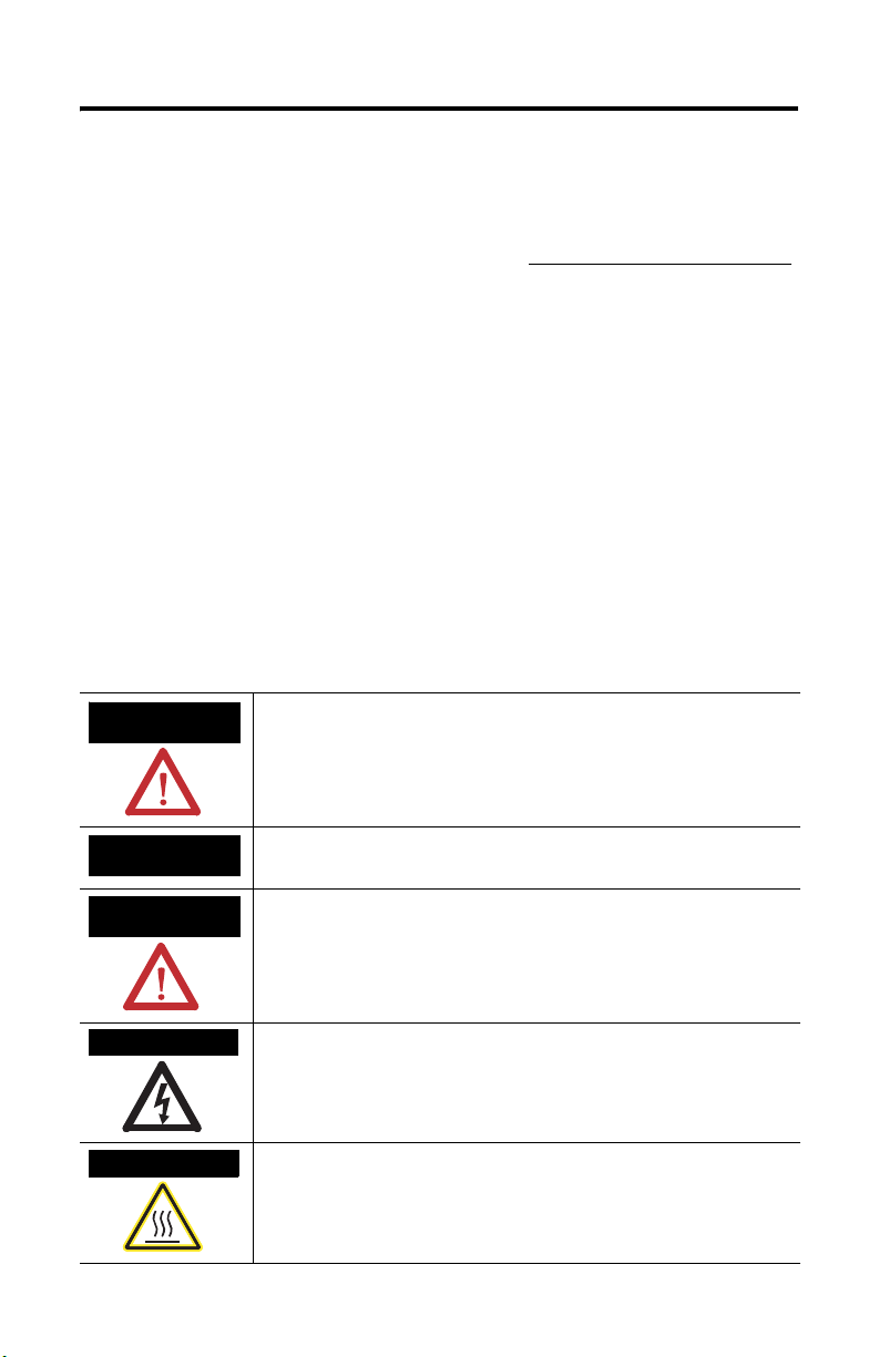
Throughout this manual, when necessary, we use notes to make you aware of safety considerations.
)
WARNING
Identifies information about practices or circumstances that can cause
an explosion in a hazardous environment, which may lead to personal
injury or death, property damage, or economic loss.
IMPORTANT
ATTENTION
Identifies information that is critical for successful application and
understanding of the product.
Identifies information about practices or circumstances that can lead to
personal injury or death, property damage, or economic loss. Attentions
help you to identify a hazard, avoid a hazard, and recognize the
consequences.
SHOCK HAZARD
Labels may be on or inside the equipment, for example, a drive or
motor, to alert people that dangerous voltage may be present.
BURN HAZARD
Labels may be on or inside the equipment, for example, a drive or
motor, to alert people that surfaces may reach dangerous temperatures.
Publication 2093-IN004A-EN-P - December 2006
Page 3
Kinetix 2000 Power Rail 3
Before You Begin
Remove all packing material, wedges, and braces from within and around the components.
After unpacking, check the item name-plate catalog number against the purchase order.
Kinetix 2000 Power Rail Box Contents
Drive Component Ships With
Power Rail • One braided 100 mm (3.9 in.) ground strap
• This manual, Installation Instructions, publication 2093-IN004.
IMPORTANT
To improve the bond between the power rail and subpanel, construct your
subpanel out of zinc plated (paint-free) steel.
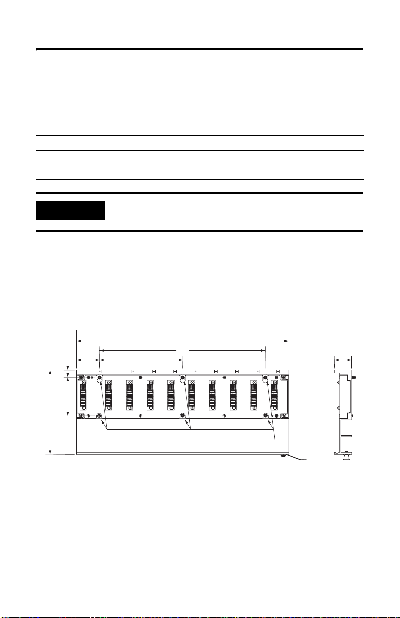
Dimensions
Mounting dimensions for the Kinetix 2000 power rail are shown in the figure and table below.
Kinetix 2000 Power Rail Approximate Dimensions
Dimensions are in millimeters (inches).
A
15.1
(0.59)
167.5
(6.59)
76.0
(2.99)
45
(1.77)
2093-PRS8S
B
C
M4 Mounting Screws
32.66
(1.29)
Publication 2093-IN004A-EN-P - December 2006
Page 4

4 Kinetix 2000 Power Rail
Kinetix 2000 Power Rail Dimensions
Catalog
Number
Power Rail
Axis
A
mm
(in.)
B
mm
(in.)
C
mm
(in.)
2093-PRS1 1 90.0 (3.54) N/A N/A
2093-PRS2 2 130.0 (5.12) 40.0 (1.58) N/A
2093-PRS3 3 170.0 (6.69) 80.0 (3.15) N/A
2093-PRS4 4 210.0 (8.27) 120.0 (4.72) N/A
2093-PRS5 5 250.0 (9.84) 160.0 (6.30) N/A
2093-PRS7 7 330.0 (12.99) 240.0 (9.45) 120.0 (4.72)
2093-PRS8S 8 410.0 (16.14) 320.0 (12,60) 160.0 (6.30)
Mount the Power Rail
The Kinetix 2000 power rail comes in several lengths. Power rails will support one integrated
axis module, additional axis modules, and a shunt module (catalog numbers 2093-AC05-MPx,
2093-AMPx, 2093-AM0x, and 2093-ASP06). Additional open slots must have a slot filler
module (2093-PRF) installed to provide continuity for control signals and system power.
Dimension, Approx.
ATTENTION
These procedures assume you have prepared your panel and understand
how to bond your system.
Refer to the Kinetix 2000 Multi-axis Servo Drive User Manual,
publication 2093-UM001, for detailed instructions on how to ground and
bond your power rail.
Follow these steps to mount a Kinetix 2000 power rail.
1. Lay out the position for your power rail in the enclosure.
For panel layout recommendations, refer to the Kinetix 2000 Multi-axis Servo Drive
User Manual, publication 2093-UM001. Mounting hole dimensions are provided in
the figure and table.
2. Attach the power rail to the cabinet.
The recommended mounting hardware is M4 metric bolts.
Publication 2093-IN004A-EN-P - December 2006
Page 5

Kinetix 2000 Power Rail 5
For bonding techniques to effectively reduce high-frequency noise, refer to the
System Design for Control of Electrical Noise Reference Manual, publication
GMC-RM001.
3. Tighten all mounting fasteners.
4. Attach the braided grounding strap between the ground stud and a bonded cabinet
ground, as shown in the following figure.
Attaching the Braided Ground Strap
Kinetix 2000 Power Rail
(2093-PRS3 shown)
Bonded Cabinet
Ground Bus
Ground Grid or Power
Power Rail
Ground Stud
Braided Ground Strap
100 mm (3.9 in.)
Distribution Ground
Publication 2093-IN004A-EN-P - December 2006
Page 6

6 Kinetix 2000 Power Rail
Additional Resources
The following documents contain additional information concerning related Allen-Bradley
products.
For Read This Document Publication Number
Information on installing,
configuring, startup,
troubleshooting, and applications
for your Kinetix 2000 servo drive
system
Information on the installation of
your Kinetix 2000 axis modules
Information on the installation of
your Kinetix 2000 and shunt
modules
Information on the installation of
your Kinetix 2000 slot filler
module
Information, examples, and
techniques designed to minimize
system failures caused by
electrical noise
Specifications, motor/servo-drive
system combinations, and
accessories for Kinetix motion
control products
Online product selection and
system configuration tools,
including AutoCAD (DXF) drawings
For declarations of conformity
(DoC) currently available from
Rockwell Automation
A glossary of industrial
automation terms and
abbreviations
Kinetix 2000 Multi-axis Servo
Drive User Manual
Kinetix 2000 Axis Module
Installation Instructions
Kinetix 2000 Shunt Module
Installation Instructions
Kinetix 2000 Slot Filler Module
Installation Instructions
System Design for Control of
Electrical Noise Reference
Manual
EMC Noise Management DVD GMC-SP001
Kinetix Motion Control
Selection Guide
Rockwell Automation
Configuration and Selection
Tools website
Rockwell Automation Product
Certification website
Rockwell Automation
Industrial Automation Glossary
2093-UM001
2093-IN001
2093-IN002
2093-IN003
GMC-RM001
GMC-SG001
http://www.ab.com/e-tools/
http://www.rockwellautomation.com/
products/certification
AG-7.1
You can view or download publications at http://literature.rockwellautomation.com
. To
order paper copies of technical documentation, contact your local Rockwell Automation
distributor or sales representative.
Publication 2093-IN004A-EN-P - December 2006
Page 7

Notes:
Kinetix 2000 Power Rail 7
Publication 2093-IN004A-EN-P - December 2006
Page 8

Rockwell Automation Support
Rockwell Automation provides technical information on the Web to assist you in using its
products. At http://support.rockwellautomation.com
knowledge base of FAQs, technical and application notes, sample code and links to software
service packs, and a MySupport feature that you can customize to make the best use of these
tools.
For an additional level of technical phone support for installation, configuration, and
troubleshooting, we offer TechConnect Support programs. For more information, contact
your local distributor or Rockwell Automation representative, or visit
http://support.rockwellautomation.com
.
Installation Assistance
If you experience a problem with a hardware module within the first 24 hours of installation,
please review the information that's contained in this manual. You can also contact a special
Customer Support number for initial help in getting your module up and running.
United States 1.440.646.3223
Monday – Friday, 8am – 5pm EST
Outside United States Please contact your local Rockwell Automation representative for any technical
support issues.
New Product Satisfaction Return
Rockwell tests all of its products to ensure that they are fully operational when shipped from
the manufacturing facility. However, if your product is not functioning, it may need to be
returned.
United States Contact your distributor. You must provide a Customer Support case number (see
phone number above to obtain one) to your distributor in order to complete the return
process.
Outside United States Please contact your local Rockwell Automation representative for return procedure.
, you can find technical manuals, a
Allen-Bradley, CompactLogix, ControlLogix, Kinetix, Rockwell Automation, SoftLogix, and TechConnect are trademarks of Rockwell
Automation, Inc.
Trademarks not belonging to Rockwell Automation are the property of their respective companies.
Publication 2093-IN004A-EN-P - December 2006
Copyright © 2006 Rockwell Automation, Inc. A ll rights reserved. Printed in t he U.S.A.
 Loading...