

Page 1

Installation Instructions
Kinetix 2000 Power Rail
(Cat. No. 2093-PRS1, 2093-PRS2, 2093-PRS3, 2093-PRS4, 2093-PRS5,
2093-PRS7, 2093-PRS8S )
Inside ...
English Section . . . . . . . . . . . . . . . . 3
Français . . . . . . . . . . . . . . . . . . . . . 11
Deutscher Abschnitt . . . . . . . . . . . 19
Sezione in Italiano . . . . . . . . . . . . . 27
Sección en español . . . . . . . . . . . . 35
Seção em português . . . . . . . . . . . . 43
Japanese . . . . . . . . . . . . . . . . . . . . 51
Korean . . . . . . . . . . . . . . . . . . . . . . 59
Chinese . . . . . . . . . . . . . . . . . . . . . 67
Publication 2093-IN004A-MU-P - December 2006
Page 2

2
Publication 2093-IN004A-MU-P - December 2006
Page 3

Installation Instructions
Kinetix 2000 Power Rail
Catalog Numbers 2093-PRS1, 2093-PRS2, 2093-PRS3, 2093-PRS4,
2093-PRS5, 2093-PRS7, 2093-PRS8S
Topic Page
About This Publication 3
Important User Information 4
Before You Begin 5
Mount the Power Rail 6
Additional Resources 8
About This Publication
This publication provides installation instructions for a Kinetix 2000 power rail (PR). Use
these instructions for mounting your power rail to the panel.
The power rail distributes power and control signals to Kinetix 2000 axis modules that power
and control servo motors or other devices producing motion. The power rail provides a
common mounting mechanism for the modules that comprise a Kinetix 2000 motion system
of one to eight axes.
Refer to the Kinetix 2000 Multi-axis Servo Drive User Manual, publication 2093-UM001, for
power up procedures, troubleshooting information, and instructions on integrating a
Kinetix 2000 system with ControlLogix, CompactLogix, and SoftLogix modules or PCI
cards. The user manual provides detailed wiring examples, and information about installing or
removing equipment and accessories not described in this document.
Publication 2093-IN004A-MU-P - December 2006
Page 4

4 Kinetix 2000 Power Rail
Important User Information
Solid state equipment has operational characteristics differing from those of electromechanical equipment.
Safety Guidelines for the Application, Installation and Maintenance of Solid State Controls (publication SGI-1.1
available from your local Rockwell Automation sales office or online at http://literature.rockwellautomation.com
describes some important differences between solid state equipment and hard-wired electromechanical devices.
Because of this difference, and also because of the wide variety of uses for solid state equipment, all persons
responsible for applying this equipment must satisfy themselves that each intended application of this
equipment is acceptable.
In no event will Rockwell Automation, Inc. be responsible or liable for indirect or consequential damages
resulting from the use or application of this equipment.
The examples and diagrams in this manual are included solely for illustrative purposes. Because of the many
variables and requirements associated with any particular installation, Rockwell Automation, Inc. cannot assume
responsibility or liability for actual use based on the examples and diagrams.
No patent liability is assumed by Rockwell Automation, Inc. with respect to use of information, circuits,
equipment, or software described in this manual.
Reproduction of the contents of this manual, in whole or in part, without written permission of Rockwell
Automation, Inc., is prohibited.
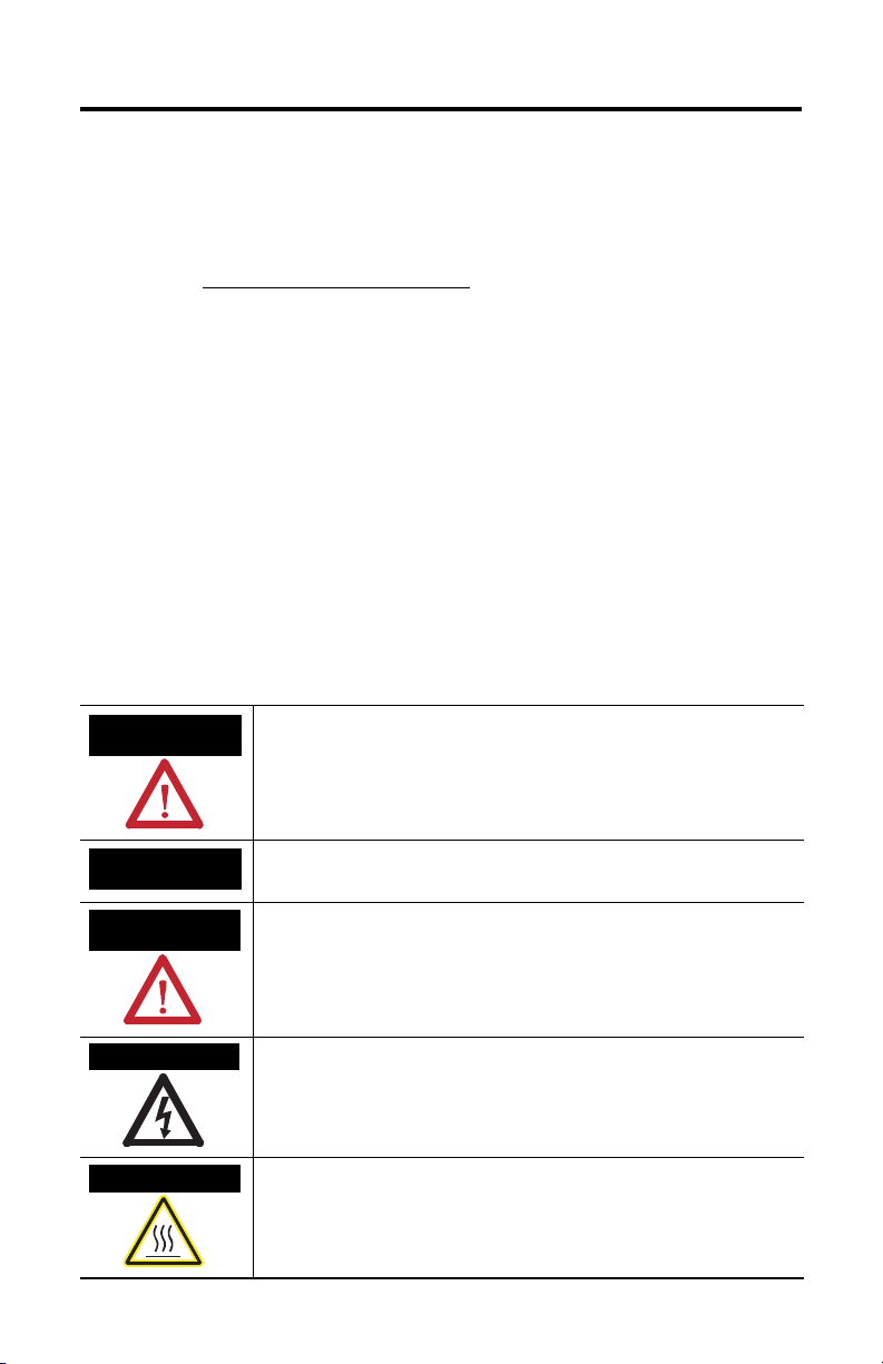
Throughout this manual, when necessary, we use notes to make you aware of safety considerations.
)
WARNING
Identifies information about practices or circumstances that can cause
an explosion in a hazardous environment, which may lead to personal
injury or death, property damage, or economic loss.
IMPORTANT
ATTENTION
Identifies information that is critical for successful application and
understanding of the product.
Identifies information about practices or circumstances that can lead to
personal injury or death, property damage, or economic loss. Attentions
help you to identify a hazard, avoid a hazard, and recognize the
consequences.
SHOCK HAZARD
Labels may be on or inside the equipment, for example, a drive or
motor, to alert people that dangerous voltage may be present.
BURN HAZARD
Labels may be on or inside the equipment, for example, a drive or
motor, to alert people that surfaces may reach dangerous temperatures.
Publication 2093-IN004A-MU-P - December 2006
Page 5
Kinetix 2000 Power Rail 5
Before You Begin
Remove all packing material, wedges, and braces from within and around the components.
After unpacking, check the item name-plate catalog number against the purchase order.
Kinetix 2000 Power Rail Box Contents
Drive Component Ships With
Power Rail • One braided 100 mm (3.9 in.) ground strap
• This manual, Installation Instructions, publication 2093-IN004.
IMPORTANT
To improve the bond between the power rail and subpanel, construct your
subpanel out of zinc plated (paint-free) steel.
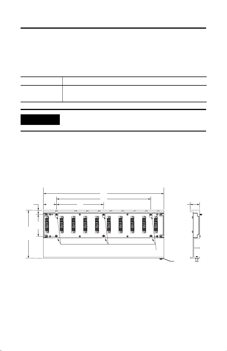
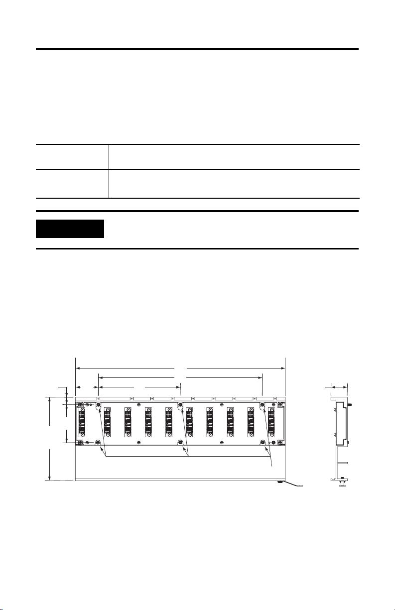
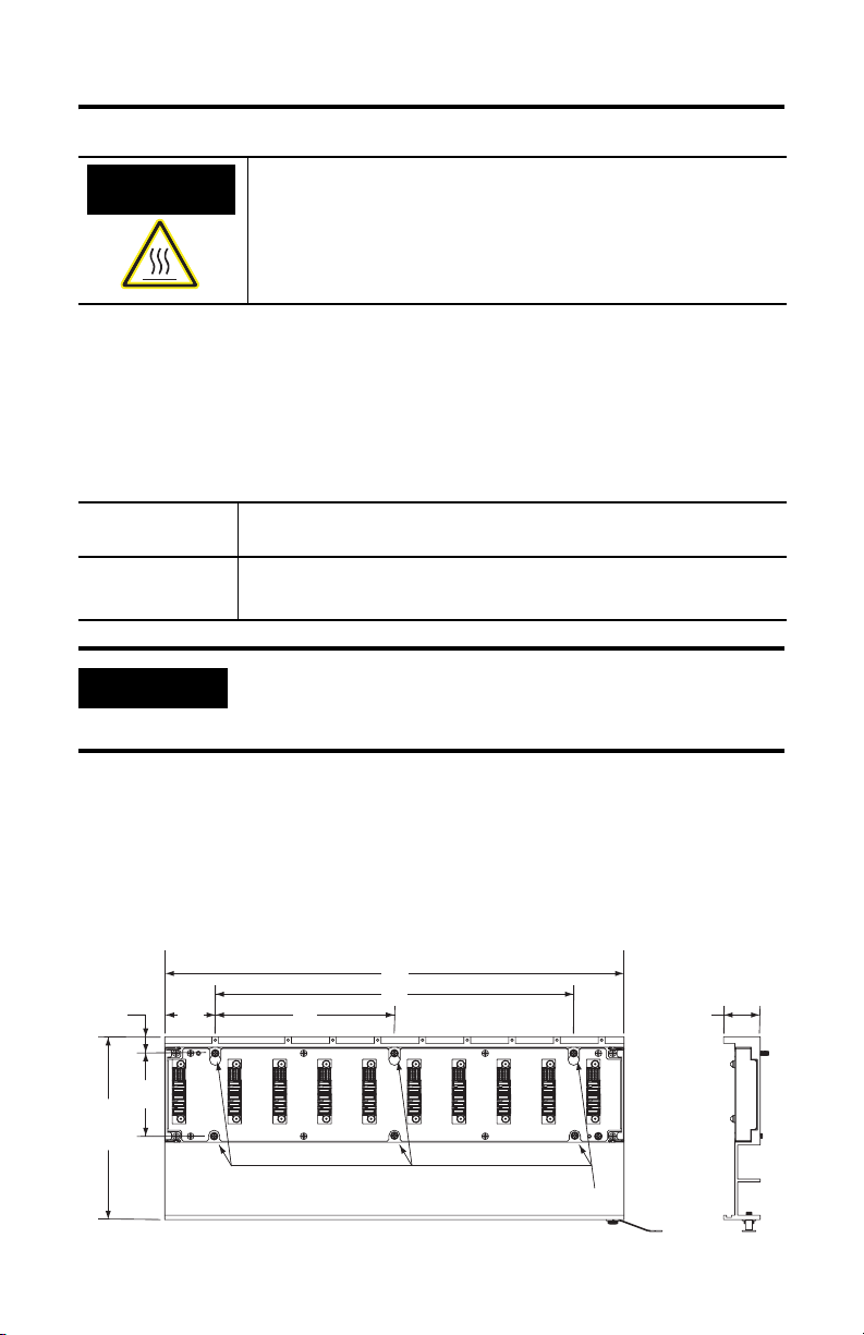
Dimensions
Mounting dimensions for the Kinetix 2000 power rail are shown in the figure and table below.
Kinetix 2000 Power Rail Approximate Dimensions
Dimensions are in millimeters (inches).
A
15.1
(0.59)
167.5
(6.59)
76.0
(2.99)
45
(1.77)
2093-PRS8S
C
B
M4 Mounting Screws
32.66
(1.29)
Publication 2093-IN004A-MU-P - December 2006
Page 6
6 Kinetix 2000 Power Rail
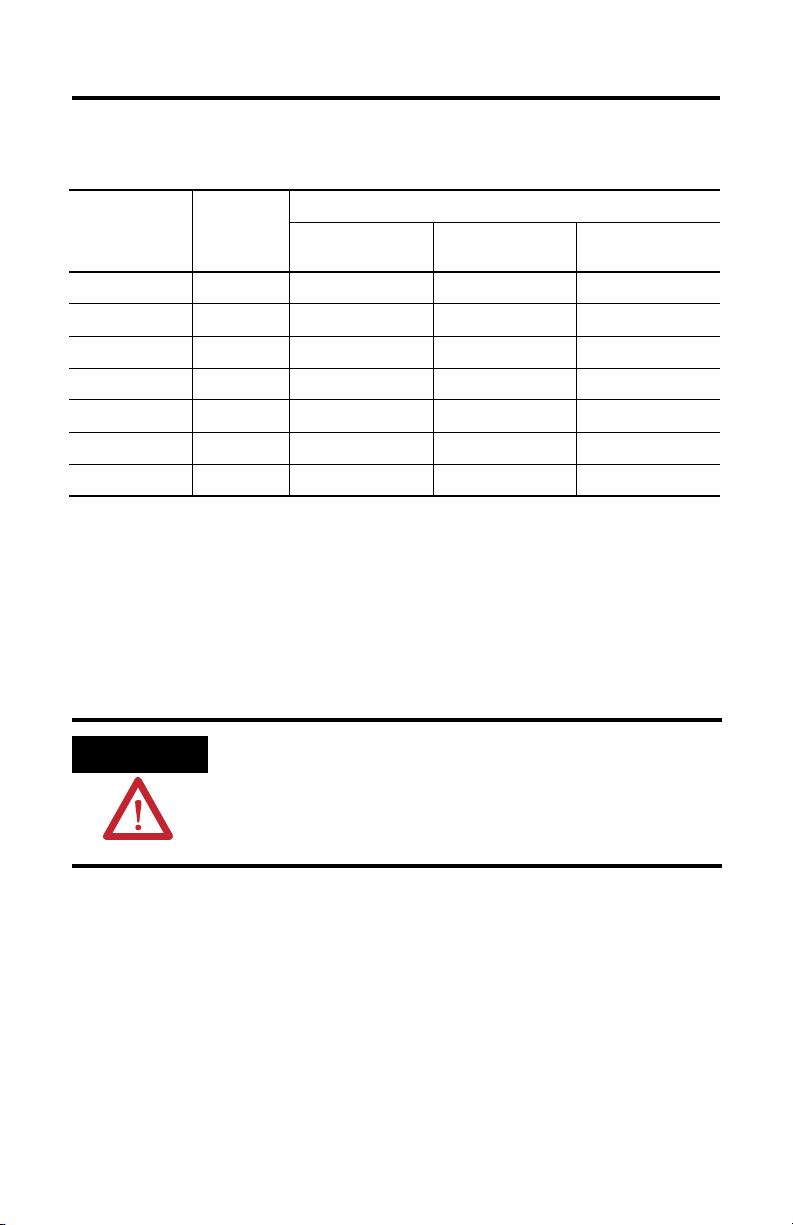
Kinetix 2000 Power Rail Dimensions
Catalog
Number
Power Rail
Axis
Dimension, Approx.
A
mm (in.)
B
mm (in.)
C
mm (in.)
2093-PRS1 1 90.0 (3.54) N/A N/A
2093-PRS2 2 130.0 (5.12) 40.0 (1.58) N/A
2093-PRS3 3 170.0 (6.69) 80.0 (3.15) N/A
2093-PRS4 4 210.0 (8.27) 120.0 (4.72) N/A
2093-PRS5 5 250.0 (9.84) 160.0 (6.30) N/A
2093-PRS7 7 330.0 (12.99) 240.0 (9.45) 120.0 (4.72)
2093-PRS8S 8 410.0 (16.14) 320.0 (12,60) 160.0 (6.30)
Mount the Power Rail
The Kinetix 2000 power rail comes in several lengths. Power rails will support one integrated
axis module, additional axis modules, and a shunt module (catalog numbers 2093-AC05-MPx,
2093-AMPx, 2093-AM0x, and 2093-ASP06). Additional open slots must have a slot filler
module (2093-PRF) installed to provide continuity for control signals and system power.
ATTENTION
These procedures assume you have prepared your panel and understand
how to bond your system.
Refer to the Kinetix 2000 Multi-axis Servo Drive User Manual,
publication 2093-UM001, for detailed instructions on how to ground and
bond your power rail.
Follow these steps to mount a Kinetix 2000 power rail.
1. Lay out the position for your power rail in the enclosure.
For panel layout recommendations, refer to the Kinetix 2000 Multi-axis Servo Drive
User Manual, publication 2093-UM001. Mounting hole dimensions are provided in
the figure and table.
2. Attach the power rail to the cabinet.
The recommended mounting hardware is M4 metric bolts.
Publication 2093-IN004A-MU-P - December 2006
Page 7

Kinetix 2000 Power Rail 7
For bonding techniques to effectively reduce high-frequency noise, refer to the
System Design for Control of Electrical Noise Reference Manual, publication
GMC-RM001.
3. Tighten all mounting fasteners.
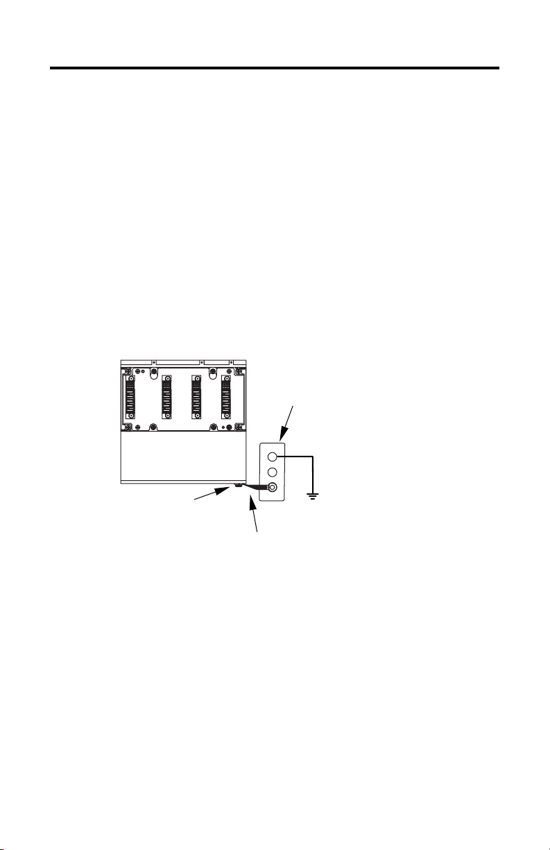
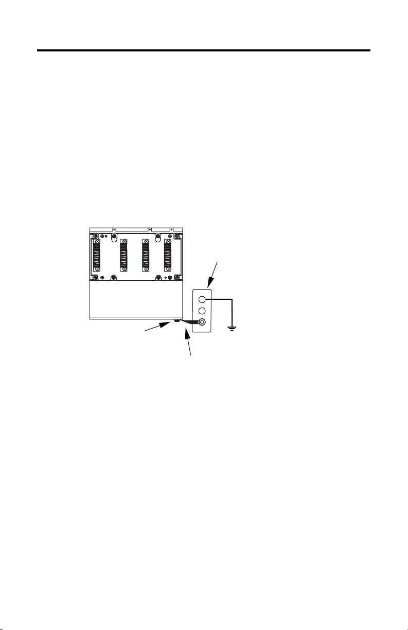
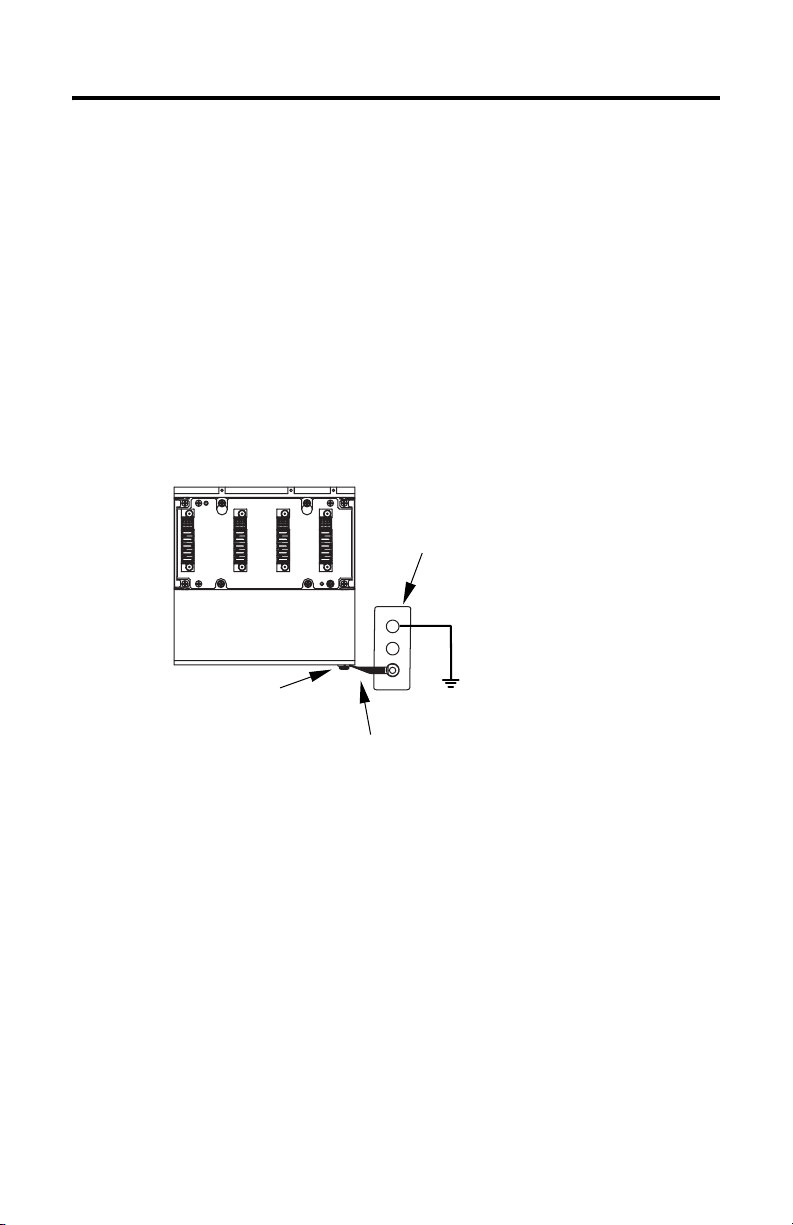
4. Attach the braided grounding strap between the ground stud and a bonded cabinet
ground, as shown in the following figure.
Attaching the Braided Ground Strap
Kinetix 2000 Power Rail
(2093-PRS3 shown)
Bonded Cabinet
Ground Bus
Ground Grid or Power
Power Rail
Ground Stud
Braided Ground Strap
100 mm (3.9 in.)
Distribution Ground
Publication 2093-IN004A-MU-P - December 2006
Page 8
8 Kinetix 2000 Power Rail
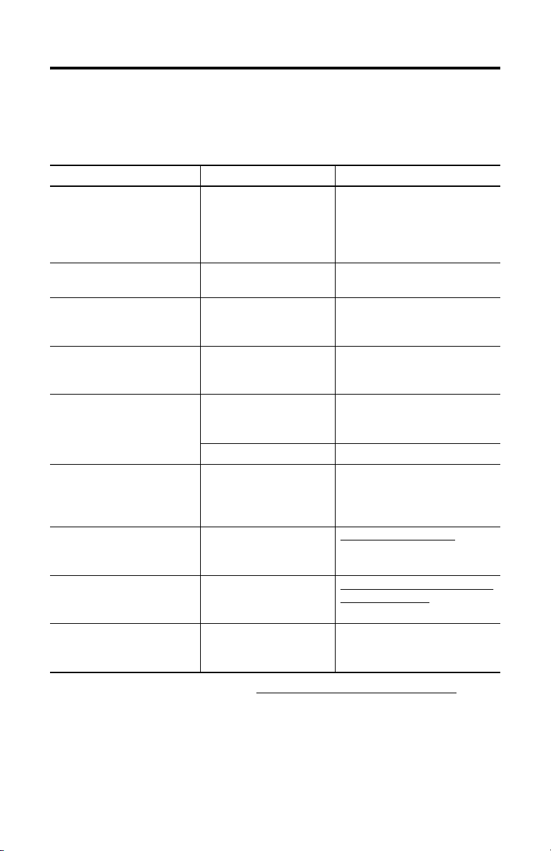
Additional Resources
The following documents contain additional information concerning related Allen-Bradley
products.
For Read This Document Publication Number
Information on installing,
configuring, startup,
troubleshooting, and applications
for your Kinetix 2000 servo drive
system
Information on the installation of
your Kinetix 2000 axis modules
Information on the installation of
your Kinetix 2000 and shunt
modules
Information on the installation of
your Kinetix 2000 slot filler
module
Information, examples, and
techniques designed to minimize
system failures caused by
electrical noise
Specifications, motor/servo-drive
system combinations, and
accessories for Kinetix motion
control products
Online product selection and
system configuration tools,
including AutoCAD (DXF) drawings
For declarations of conformity
(DoC) currently available from
Rockwell Automation
A glossary of industrial
automation terms and
abbreviations
Kinetix 2000 Multi-axis Servo
Drive User Manual
Kinetix 2000 Axis Module
Installation Instructions
Kinetix 2000 Shunt Module
Installation Instructions
Kinetix 2000 Slot Filler Module
Installation Instructions
System Design for Control of
Electrical Noise Reference
Manual
EMC Noise Management DVD GMC-SP001
Kinetix Motion Control
Selection Guide
Rockwell Automation
Configuration and Selection
Tools website
Rockwell Automation Product
Certification website
Rockwell Automation
Industrial Automation Glossary
2093-UM001
2093-IN001
2093-IN002
2093-IN003
GMC-RM001
GMC-SG001
http://www.ab.com/e-tools/
http://www.rockwellautomation.com/
products/certification
AG-7.1
You can view or download publications at http://literature.rockwellautomation.com
. To
order paper copies of technical documentation, contact your local Rockwell Automation
distributor or sales representative.
Publication 2093-IN004A-MU-P - December 2006
Page 9

Notes:
Kinetix 2000 Power Rail 9
Publication 2093-IN004A-MU-P - December 2006
Page 10
Rockwell Automation Support
Rockwell Automation provides technical information on the Web to assist you in using its
products. At http://support.rockwellautomation.com
knowledge base of FAQs, technical and application notes, sample code and links to software
service packs, and a MySupport feature that you can customize to make the best use of these
tools.
For an additional level of technical phone support for installation, configuration, and
troubleshooting, we offer TechConnect Support programs. For more information, contact
your local distributor or Rockwell Automation representative, or visit
http://support.rockwellautomation.com
.
Installation Assistance
If you experience a problem with a hardware module within the first 24 hours of installation,
please review the information that's contained in this manual. You can also contact a special
Customer Support number for initial help in getting your module up and running.
United States 1.440.646.3223
Monday – Friday, 8am – 5pm EST
Outside United States Please contact your local Rockwell Automation representative for any technical
support issues.
New Product Satisfaction Return
Rockwell tests all of its products to ensure that they are fully operational when shipped from
the manufacturing facility. However, if your product is not functioning, it may need to be
returned.
United States Contact your distributor. You must provide a Customer Support case number (see
phone number above to obtain one) to your distributor in order to complete the return
process.
Outside United States Please contact your local Rockwell Automation representative for return procedure.
, you can find technical manuals, a
Allen-Bradley, CompactLogix, ControlLogix, Kinetix, Rockwell Automation, SoftLogix, and TechConnect are trademarks of Rockwell
Automation, Inc.
Trademarks not belonging to Rockwell Automation are the property of their respective companies.
Publication 2093-IN004A-MU-P - December 2006
Copyright © 2006 Rockwell Automation, Inc. All rights reserved. Printed in the U.S.A.
Page 11

Notice d’installation
Rail d’alimentation pour Kinetix 2000
Références 2093-PRS1, 2093-PRS2, 2093-PRS3, 2093-PRS4, 2093-PRS5,
2093-PRS7, 2093-PRS8S
Rubrique Page
A propos de cette publication 11
Informations importantes destinées à l’utilisateur 12
Avant de commencer 13
Montage du rail d’alimentation 14
Documentation connexe 16
A propos de cette publication
Cette publication indique comment installer un rail d’alimentation pour Kinetix 2000. Utilisez
ces instructions pour fixer le rail d’alimentation sur le panneau.
Le rail d’alimentation véhiculent des signaux de commande et alimentent les modules d’axe
Kinetix 2000 qui, eux-mêmes, alimentent et commandent des servomoteurs ou d’autres
équipements producteurs de mouvements. Ce rail offre un mécanisme de montage commun
pour les modules qui composent un système de commande d’axes Kinetix 2000 de un à huit
axes.
Pour savoir comment mettre sous tension, dépanner et intégrer un système Kinetix 2000 avec
des modules ControlLogix, CompactLogix et SoftLogix ou des cartes PCI, reportez-vous au
manuel d’utilisation des modules d’axe Kinetix 2000 (Kinetix 2000 Multi-axis Servo Drive
User Manual, publication 2093-UM001). Le manuel utilisateur donne des exemples de câblage
détaillés, ainsi que des informations sur l’installation et le démontage des équipements et des
accessoires non décrits dans la présente notice.
Publication 2093-IN004A-MU-P – Décembre 2006
Page 12
12 Rail d’alimentation pour Kinetix 2000
Informations importantes destinées à l’utilisateur
Les équipements électroniques possèdent des caractéristiques de fonctionnement différentes de celles des
équipements électromécaniques. La publication SGI-1.1, « Safety Guidelines for the Application, Installation and
Maintenance of Solid State Controls » (disponible auprès de votre agence commerciale Rockwell Automation ou
en ligne sur le site http://literature.rockwellautomation.com)
ces différences et de la diversité des utilisations des produits décrits dans le présent manuel, les personnes qui
en sont responsables doivent s’assurer de l’acceptabilité de chaque application.
La société Rockwell Automation, Inc. ne saurait en aucun cas être tenue pour responsable ni être redevable des
dommages indirects ou consécutifs à l’utilisation ou à l’application de cet équipement.
Les exemples et schémas contenus dans ce manuel sont présentés à titre indicatif seulement. En raison du
nombre important de variables et d’impératifs associés à chaque installation, la société Rockwell Automation,
Inc. ne saurait être tenue pour responsable ni être redevable des suites d’utilisation réelle basée sur les
exemples et schémas présentés dans ce manuel.
La société Rockwell Automation, Inc. décline également toute responsabilité en matière de propriété
intellectuelle et industrielle concernant les informations, circuits, équipements ou logiciels décrits dans ce
manuel.
Toute reproduction totale ou partielle du présent manuel sans autorisation écrite de la société
Rockwell Automation, Inc. est interdite.
Des remarques sont utilisées tout au long de manuel pour attirer votre attention sur les mesures de sécurité
à prendre en compte :
décrit certaines de ces différences. En raison de
AVERTISSEMENT
Actions ou situations risquant de provoquer une explosion dans un
environnement dangereux et d’entraîner des blessures pouvant être
mortelles, des dégâts matériels ou des pertes financières.
IMPORTANT
ATTENTION
Informations particulièrement importantes dans le cadre de l’utilisation
du produit.
Actions ou situations risquant d’entraîner des blessures pouvant être
mortelles, des dégâts matériels ou des pertes financières. Ces mises en
garde vous aident à identifier un danger, à l’éviter et à en discerner les
conséquences.
DANGER D’ELECTROCUTION
Les étiquettes ci-contre, placées sur l’équipement (un variateur ou un
moteur par ex.) ou à l’intérieur, signalent la présence éventuelle de
tensions électriques dangereuses.
RISQUE DE BRULURE
Les étiquettes ci-contre, placées sur l’équipement (un variateur ou un
moteur par ex.) ou à l’intérieur, indiquent au personnel que certaines
surfaces peuvent atteindre des températures particulièrement élevées.
Publication 2093-IN004A-MU-P – Décembre 2006
Page 13
Rail d’alimentation pour Kinetix 2000 13
Avant de commencer
Retirez tous les matériaux d’emballage, les cales et les sangles qui fixent les différents
équipements. Une fois l’équipement déballé, comparez la référence indiquée sur la plaque
signalétique de l’équipement et celle figurant sur le bon de commande.
Contenu de la boîte Rail d’alimentation pour Kinetix 2000
Composant du
variateur
Rail d’alimentation • une tresse de mise à la masse de 100 mm ;
Livré avec
• cette notice d’installation (publication 2093-IN004).
IMPORTANT
Pour un meilleur contact entre le rail d’alimentation et le panneau de
montage, fabriquez ce dernier en acier galvanisé (sans peinture).
Dimensions
Les dimensions de montage du rail d’alimentation pour Kinetix 2000 sont indiquées sur la
figure et dans le tableau ci-après.
Dimensions approximatives du rail d’alimentation pour Kinetix 2000
Dimensions en millimètres (pouces).
A
15.1
(0.59)
167.5
(6.59)
76.0
(2.99)
45
(1.77)
2093-PRS8S
C
B
Vis de fixation M4
M4 Mounting Screws
32.66
(1.29)
Publication 2093-IN004A-MU-P – Décembre 2006
Page 14
14 Rail d’alimentation pour Kinetix 2000
Dimensions du rail d’alimentation pour Kinetix 2000
Référence
2093-PRS1 1 90 (3,54) – –
2093-PRS2 2 130 (5,12) 40 (1,58) –
2093-PRS3 3 170 (6,69) 80 (3,15) –
2093-PRS4 4 210 (8,27) 120 (4,72) –
2093-PRS5 5 250 (9,84) 160 (6,30) –
2093-PRS7 7 330 (12,99) 240 (9,45) 120 (4,72)
2093-PRS8S 8 410 (16,14) 320 (12,60) 160 (6,30)
Nombre
d’axes du rail
d’alimentation
Dimension approx.
A
mm (pouces)Bmm (pouces)Cmm (pouce)
Montage du rail d’alimentation
Le rail d’alimentation pour Kinetix 2000 existe en différentes longueurs. Les rails
d’alimentation peuvent recevoir un module d’axe intégré, des modules d’axe supplémentaires
et un module résistance de freinage (références 2093-AC05-MPx, 2093-AMPx, 2093-AM0x et
2093-ASP06). Un cache pour emplacement vide (2093-PRF) doit être installé sur chaque
emplacement vide pour assurer la continuité des signaux de commande et l’alimentation du
système.
ATTENTION
Pour monter un rail d’alimentation pour Kinetix 2000, procédez comme suit.
1. Tracez la position de votre rail d’alimentation dans l’armoire.
Pour des recommandations sur l’agencement de votre panneau, reportez-vous au
manuel d’utilisation des Kinetix 2000 (Kinetix 2000 Multi-axis Servo Drive User
Manual, publication 2093-UM001). Les dimensions des orifices de montage sont
indiquées sur la figure et dans le tableau ci-dessous.
Publication 2093-IN004A-MU-P – Décembre 2006
Cette procédure suppose que vous ayez préparé votre panneau et que
vous savez relier votre système.
Pour des informations détaillées sur la procédure de mise à la terre de
votre rail d’alimentation, reportez-vous au manuel d’utilisation des
Kinetix 2000 (Kinetix 2000 Multi-axis Servo Drive User Manual,
publication 2093-UM001).
Page 15
Rail d’alimentation pour Kinetix 2000 15
2. Fixez le rail d’alimentation à l’armoire.
Nous vous recommandons d’utiliser des boulons métriques M4.
Pour connaître les techniques de mise à la masse permettant de réduire efficacement
les parasites à haute fréquence, reportez-vous à la publication GMC-RM001, System
Design for Control of Electrical Noise Reference Manual.
3. Serrez toutes les fixations.
4. Reliez la tresse de mise à la masse entre le plot de mise à la terre du rail et un
collecteur de terre de l’armoire relié, comme le montre la figure ci-dessous.
Fixation de la tresse de mise à la masse
Rail d’alimentation pour Kinetix 2000
(2093-PRS3 représenté)
Collecteur de terre
de l’armoire relié
Plot de mise à la terre
du rail d’alimentation
Grille de terre ou
terre de l’alimentation secteur
Tresse de mise à la masse
de 100 mm
Publication 2093-IN004A-MU-P – Décembre 2006
Page 16

16 Rail d’alimentation pour Kinetix 2000
Documentation connexe
Les documents suivants contiennent des informations complémentaires sur les produits
Allen-Bradley connexes.
Pour Voir Référence
des informations sur l’installation,
la configuration, la mise en
service, le dépannage et les
applications de votre système
variateur brushless Kinetix 2000
des informations sur l’installation
de votre module d’axe
Kinetix 2000
des informations sur l’installation
de votre module résistance de
freinage pour Kinetix 2000
des informations sur l’installation
de votre cache d’emplacement
pour Kinetix 2000
des informations, des exemples et
des techniques pour minimiser les
défaillances du système
provoquées par des parasites
électriques
les caractéristiques, les
combinaisons de moteurs /
variateurs brushless et les
accessoires pour les produits de
commande d’axe Kinetix
choisir en ligne des produits et
outils de configuration du
système, notamment des schémas
autocad (DXF)
des déclarations de conformité
(DoC) disponibles auprès de
Rockwell Automation
un glossaire des termes et
abréviations utilisés en
automatisation industrielle
Kinetix 2000 Multi-axis Servo
Drive User Manual
Module d’axe intégré et
module d’axe Kinetix 2000 –
Notice d’installation
Module résistance de freinage
pour Kinetix 2000 – Notice
d’installation
Cache d’emplacement pour
Kinetix 2000 – Notice
d’installation
System Design for Control of
Electrical Noise Reference
Manual
EMC Noise Management DVD GMC-SP001
Kinetix Motion Control
Selection Guide
Site Internet des outils de
configuration et de sélection
de Rockwell Automation
Site Internet consacré à la
certification des produits
Rockwell Automation
Rockwell Automation
Industrial Automation Glossary
2093-UM001
2093-IN001
2093-IN002
2093-IN003
GMC-RM001
GMC-SG001
http://www.ab.com/e-tools/
http://www.rockwellautomation.com/
products/certification
AG-7.1
Vous pouvez consulter ou télécharger les publications à partir du site
http://literature.rockwellautomation.com
. Pour commander un exemplaire imprimé d’un
document technique, contactez votre distributeur ou votre représentant
Rockwell Automation.
Publication 2093-IN004A-MU-P – Décembre 2006
Page 17

Notes :
Rail d’alimentation pour Kinetix 2000 17
Publication 2093-IN004A-MU-P – Décembre 2006
Page 18
Assistance Rockwell Automation
Rockwell Automation fournit des informations techniques sur Internet pour vous aider à utiliser
ses produits. Sur le site http://support.rockwellautomation.com
techniques, une base de connaissances regroupant les questions fréquemment posées, des notes
techniques et des profils d’application, des exemples de code et des liens vers des mises à jour de
logiciels (service pack). Vous y trouverez également la rubrique « MySupport », que vous pouvez
personnaliser pour utiliser au mieux ces outils.
Si vous souhaitez une assistance technique supplémentaire par téléphone pour l’installation, la
configuration et le dépannage de vos produits, nous proposons les programmes d’assistance
TechConnect. Pour de plus amples informations, contactez votre distributeur ou votre
représentant Rockwell Automation, ou allez sur le site http://support.rockwellautomation.com
Aide à l’installation
En cas de problème sur un module matériel dans les 24 heures suivant son installation, consultez
les informations données dans le présent manuel. Vous pouvez également appeler l’Assistance
Rockwell Automation à un numéro spécial, afin d’obtenir de l’aide pour la mise en service de votre
module :
Pour les Etats-Unis +1.440.646.3223
du lundi au vendredi, de 8h00 à 17h00 (heure de la côte est)
Pour les autres pays Contactez votre représentant Rockwell Automation pour tout problème technique.
Procédure de retour d’un nouveau produit
Rockwell Automation teste tous ses produits pour en garantir le parfait
fonctionnement à leur sortie d’usine. Cependant, si votre produit ne fonctionne pas et doit faire
l’objet d’un retour :
Pour les Etats-Unis Contactez votre distributeur. Vous devrez lui fournir le numéro de dossier que le Centre
Pour les autres pays Contactez votre représentant Rockwell Automation local pour savoir comment procéder.
Allen-Bradley, CompactLogix, ControlLogix, Kinetix, Rockwell Automation, SoftLogix et TechConnect sont des marques commerciales de
Rockwell Automation, Inc.
Les marques commerciales n’appartenant pas à Rockwell Automation sont la propriété de leurs sociétés respectives.
d’assistance vous aura communiqué (voir le numéro de téléphone ci-dessus), afin de
procéder au retour.
, vous trouverez des manuels
.
Publication 2093-IN004A-MU-P – Décembre 2006
Copyright © 2006 Rockwell Automation, Inc. Tous droits réservés. Imprimé aux Etats-Unis.
Page 19

Installationsanleitung
Kinetix 2000-Stromschiene
Bestellnummern 2093-PRS1, 2093-PRS2, 2093-PRS3, 2093-PRS4,
2093-PRS5, 2093-PRS7, 2093-PRS8S
Thema Seite
Hinweise zu dieser Publikation 19
Wichtige Hinweise für den Anwender 20
Bevor Sie beginnen 21
Montage der Stromschiene 22
Weitere Ressourcen 24
Hinweise zu dieser Publikation
Diese Publikation enthält Anweisungen zur Installation einer Kinetix 2000-Stromschiene
(Power Rail, PR). Verwenden Sie diese Anweisungen für die Montage Ihrer Stromschiene im
Schaltschrank.
Die Stromschiene verteilt Strom und Steuersignale an Kinetix 2000-Achsmodule, die
Servomotoren oder andere Bewegung produzierende Geräte mit Strom versorgen und
steuern. Die Stromschiene bietet einen gemeinsamen Montagemechanismus für die Module,
die ein Kinetix 2000-Antriebssystem mit bis zu acht Achsen umfasst.
Siehe Kinetix 2000 Multi-axis Servo Drive User Manual, Publikation 2093-UM001 für
Einschaltprozeduren, Fehlerbehebungsinformationen und Anweisungen zur Integration
eines Kinetix 2000-Systems mit ControlLogix-, CompactLogix- und SoftLogix-Modulen oder
PCI-Karten. Das Benutzerhandbuch enthält detaillierte Verdrahtungsbeispiele und
Informationen zur Installation oder Entfernung von Geräten und Zubehörteilen, die in
diesem Dokument nicht beschrieben werden.
Publikation 2093-IN004A-MU-P – Dezember 2006
Page 20
20 Kinetix 2000-Stromschiene
Wichtige Hinweise für den Anwender
Die Betriebseigenschaften elektronischer Geräte unterscheiden sich von denen elektromechanischer Geräte. In
der Publikation SGI-1.1 Safety Guidelines for the Application, Installation, and Maintenance of Solid-State
Controls (erhältlich bei Ihrem Rockwell Automation-Vertriebsbüro oder online unter
http://literature.rockwellautomation.com
festverdrahteten elektromechanischen Geräten erläutert. Aufgrund dieser Unterschiede und der vielfältigen
Einsatzbereiche elektronischer Geräte müssen die für die Anwendung dieser Geräte verantwortlichen Personen
sicherstellen, dass die Geräte zweckgemäß eingesetzt werden.
Rockwell Automation ist in keinem Fall verantwortlich oder haftbar für indirekte Schäden oder Folgeschäden, die
durch den Einsatz oder die Anwendung dieses Geräts entstehen.
Die in diesem Handbuch aufgeführten Beispiele und Abbildungen dienen ausschließlich zur Veranschaulichung.
Aufgrund der unterschiedlichen Anforderungen der jeweiligen Anwendung kann Rockwell Automation keine
Verantwortung oder Haftung für den tatsächlichen Einsatz der Produkte auf der Grundlage dieser Beispiele und
Abbildungen übernehmen.
Rockwell Automation übernimmt keine patentrechtliche Haftung in Bezug auf die Verwendung von
Informationen, Schaltkreisen, Geräten oder Software, die in dieser Publikation beschrieben werden.
Die Vervielfältigung des Inhalts dieser Publikation, ganz oder auszugsweise, bedarf der schriftlichen
Genehmigung von Rockwell Automation.
In dieser Publikation werden folgende Hinweise verwendet, um Sie auf bestimmte Sicherheitsaspekte
aufmerksam zu machen.
) werden einige wichtige Unterschiede zwischen elektronischen und
WARNUNG
Dieser Hinweis macht Sie auf Vorgehensweisen und Zustände
aufmerksam, die in explosionsgefährdeten Umgebungen zu einer
Explosion und damit zu Verletzungen oder Tod, Sachschäden oder
wirtschaftlichen Verlusten führen können.
WICHTIG
ACHTUNG
Dieser Hinweis enthält Informationen, die für den erfolgreichen Einsatz
und das Verstehen des Produkts besonders wichtig sind.
Dieser Hinweis macht Sie auf Vorgehensweisen und Zustände
aufmerksam, die zu Verletzungen oder Tod, Sachschäden oder
wirtschaftlichen Verlusten führen können. Die Achtungshinweise helfen
Ihnen, eine Gefahr zu erkennen, die Gefahr zu vermeiden und die Folgen
abzuschätzen.
STROM-
SCHLAGGEFAHR
An der Außenseite oder im Inneren des Geräts, z. B. eines Antriebs oder
Motors, kann ein Etikett dieser Art angebracht sein, um Sie darauf
hinzuweisen, dass möglicherweise eine gefährliche Spannung anliegt.
Publikation 2093-IN004A-MU-P – Dezember 2006
Page 21
Kinetix 2000-Stromschiene 21
VERBRENNUNGS-
GEFAHR
An der Außenseite oder im Inneren des Geräts, z. B. eines Antriebs oder
Motors, kann ein Etikett dieser Art angebracht sein, um Sie darauf
hinzuweisen, dass die Oberflächen möglicherweise gefährliche
Temperaturen aufweisen.
Bevor Sie beginnen
Entfernen Sie das gesamte Verpackungsmaterial, Keile und Klammern in den und um die
Komponenten. Vergleichen Sie nach dem Auspacken die Bestellnummer auf dem
Typenschild des Geräts mit der in der Bestellung genannten Nummer.
Verpackungsinhalt Kinetix 2000-Stromschiene
Antriebskomponenten
Stromschiene • Ein geflochtenes Erdungsband von 100 mm (3,9 in.)
WICHTIG
Lieferumfang
• Dieses Handbuch, Installationsanleitung, Publikation 2093-IN004.
Um den Kontakt zwischen der Stromschiene und dem Schaltschrank zu
verbessern, konstruieren Sie den Schaltschrank aus zinkbeschichtetem
(unlackierten) Stahl.
Abmessungen
Einbau-Abmessungen für die Kinetix 2000-Stromschiene werden in der folgenden Abbildung
und Tabelle gezeigt.
Ungefähre Abmessungen der Kinetix 2000-Stromschiene
Abmessungen sind in Millimetern (Zoll) angegeben
A
15.1
(0.59)
167.5
(6.59)
76.0
(2.99)
45
(1.77)
2093-PRS8S
C
B
M4 Mounting Screws
Publikation 2093-IN004A-MU-P – Dezember 2006
32.66
(1.29)
Page 22

22 Kinetix 2000-Stromschiene
Abmessungen der Kinetix 2000-Stromschiene
Bestellnummer
Stromschiene,
Achse
Abmessung, Ca.-Angabe
A
mm (in.)
B
mm (in.)
C
mm (in.)
2093-PRS1 1 90,0 (3,54) n. v. n. v.
2093-PRS2 2 130,0 (5,12) 40,0 (1,58) n. v.
2093-PRS3 3 170,0 (6,69) 80,0 (3,15) n. v.
2093-PRS4 4 210,0 (8,27) 120,0 (4,72) n. v.
2093-PRS5 5 250,0 (9,84) 160,0 (6,30) n. v.
2093-PRS7 7 330,0 (12,99) 240,0 (9,45) 120,0 (4,72)
2093-PRS8S 8 410,0 (16,14) 320,0 (12,60) 160,0 (6,30)
Montage der Stromschiene
Die Kinetix 2000-Stromschiene ist in verschiedenen Längen verfügbar. Stromschienen
unterstützen ein integriertes Achsmodul, zusätzliche Achsmodule und ein Bremsmodul
(Bestellnummern 2093-AC05-MPx, 2093-AMPx, 2093-AM0x und 2093-ASP06). Zusätzliche
offene Steckplätze müssen für die Funktionsfähigkeit mit einem Blindmodul (2093-PRF)
abgedeckt werden.
ACHTUNG
Diese Prozeduren setzen voraus, dass Sie Ihren Schaltschrank vorbereitet
haben und wissen, wie Sie Ihr System anschließen müssen.
Siehe Kinetix 2000 Multi-axis Servo Drive User Manual, Publikation
2093-UM001 für detaillierte Anleitungen zu Erdung und Anschluss Ihrer
Stromschiene.
Halten Sie bei der Installation einer Kinetix 2000-Stromschiene diese Schritte ein.
1. Positionieren Sie Ihre Stromschiene im Gehäuse.
Für Empfehlungen zum Layout des Schaltschranks siehe Kinetix 2000 Multi-axis
Servo Drive User Manual, Publikation 2093-UM001. Die
Befestigungsloch-Abmessungen sind der Abbildung und Tabelle zu entnehmen.
2. Befestigen Sie die Stromschiene am Schaltschrank.
Die empfohlene Montagehardware besteht aus M4-Bolzen (metrisch).
Publikation 2093-IN004A-MU-P – Dezember 2006
Page 23
Kinetix 2000-Stromschiene 23
Für Anschlusstechniken zur effektiven Verringerung hochfrequenter Störungen siehe
System Design for Control of Electrical Noise Reference Manual, Publikation
GMC-RM001.
3. Ziehen Sie alle Befestigungselemente fest.
4. Befestigen Sie das geflochtene Erdungsband zwischen dem Erdungsstift und einer
angeschlossenen Schaltschrankerdung, wie in der folgenden Abbildung gezeigt.
Befestigen des geflochtenen Erdungsbands
Kinetix 2000-Stromschiene
(gezeigt: 2093-PRS3)
Angeschlossene
SchaltschrankErdungssammelleitung
Erdungsgitter oder Erde
Stromschiene
Erdungsstift
Geflochtenes Erdungsband
100 mm (3,9 in.)
Stromverteilung
Publikation 2093-IN004A-MU-P – Dezember 2006
Page 24

24 Kinetix 2000-Stromschiene
Weitere Ressourcen
Die folgenden Dokumente enthalten zusätzliche Informationen zu weiteren
Allen-Bradley-Produkten.
Informationen zu Finden Sie in diesem
Informationen zu Installation,
Konfiguration, Anlauf,
Fehlerbehebung und
Anwendungen für Ihren Kinetix
2000-Servoantrieb
Informationen zur Installation Ihrer
Kinetix 2000-Achsmodule
Informationen zur Installation
Ihres Kinetix 2000 und der
Bremsmodule
Informationen zur Installation
Ihres Kinetix 2000-Blindmoduls
Informationen, Beispiele und
Techniken, die zum Minimieren der
Systemausfälle dienen, die durch
elektrische Störungen verursacht
werden
Spezifikationen, Motor-/
Servoantriebskombinationen und
Zubehörteile für
Kinetix-Achssteuerungsprodukte
Online-Produktauswahl und
Systemkonfigurationswerkzeuge,
einschließlich
Autocad-Zeichnungen (DXF)
Konformitätserklärungen, die
derzeit von Rockwell Automation
erhältlich sind
Ein Glossar der Begriffe und
Abkürzungen, die in der
Automatisierungsindustrie
verwendet werden
Dokument
Kinetix 2000 Multi-axis Servo
Drive User Manual
Kinetix 2000 Axis Module
Installation Instructions
Kinetix 2000 Shunt Module
Installation Instructions
Kinetix 2000 Slot Filler Module
Installation Instructions
System Design for Control of
Electrical Noise Reference
Manual
DVD zum
EMV-Störungsmanagement
Kinetix Motion Control
Selection Guide
Rockwell Automation-Website
mit Konfigurations- und
Auswahlwerkzeugen
Rockwell Automation-Website
zur Produktzertifizierung
Rockwell Automation
Industrial Automation Glossary
Publikationsnummer
2093-UM001
2093-IN001
2093-IN002
2093-IN003
GMC-RM001
GMC-SP001
GMC-SG001
http://www.ab.com/e-tools/
http://www.rockwellautomation.com/
products/certification
AG-7.1
Sie können unter folgender Adresse Publikationen ansehen bzw. herunterladen:
http://literature.rockwellautomation.com
. Wenn Sie gedruckte Versionen der technischen
Dokumentation anfordern möchten, wenden Sie sich an Ihren lokalen Rockwell
Automation-Distributor oder -Vertriebsbeauftragten.
Publikation 2093-IN004A-MU-P – Dezember 2006
Page 25

Notizen:
Kinetix 2000-Stromschiene 25
Publikation 2093-IN004A-MU-P – Dezember 2006
Page 26
Kundendienst von Rockwell Automation
Rockwell Automation stellt technische Informationen über das Internet bereit, um Sie bei der
Anwendung unserer Produkte zu unterstützen. Unter
http://support.rockwellautomation.com
Wissensdatenbank mit Antworten auf häufig gestellte Fragen, technische Hinweise und
Applikationsbeispiele, Beispielcode sowie Links zu Software-Servicepaketen. Außerdem
finden Sie dort die Funktion „MySupport“, über die Sie diese Tools individuell an Ihre
Anforderungen anpassen können.
Zusätzlichen telefonischen Support für die Installation, Konfiguration und Fehlerbehebung
erhalten Sie über unsere TechConnect Support-Programme. Wenn Sie weitere Informationen
wünschen, wenden Sie sich an Ihren Distributor oder Rockwell Automation-Vertreter oder
besuchen Sie uns im Internet unter http://support.rockwellautomation.com
Unterstützung bei der Installation
Wenn innerhalb von 24 Stunden nach der Installation Probleme mit einem Hardwaremodul
auftreten, lesen Sie bitte die Informationen in diesem Handbuch. Über eine spezielle
Kundendienst-Bearbeitungsnummer erhalten Sie Unterstützung bei der Einrichtung Ihres
Moduls.
USA +1 440 646 3223
Montag bis Freitag, 8:00 Uhr bis 17:00 Uhr EST
Außerhalb der USA Bitte wenden Sie sich bei Fragen zum technischen Support an Ihren Rockwell
Automation-Vertreter.
finden Sie technische Handbücher, eine
.
Rückgabeverfahren bei neuen Produkten
Rockwell testet alle Produkte, um sicherzustellen, dass sie beim Verlassen des Werks voll
funktionstüchtig sind. Sollte das Produkt nicht ordnungsgemäß funktionieren und
zurückgegeben werden müssen, gehen Sie wie folgt vor:
USA Wenden Sie sich an Ihren Distributor. Sie müssen Ihrem Distributor eine
Kundendienst-Bearbeitungsnummer angeben (diese erhalten Sie über die oben
genannte Telefonnummer), damit das Rückgabeverfahren abgewickelt werden kann.
Außerhalb der USA Bitte wenden Sie sich bei Fragen zum Rückgabeverfahren an Ihren Rockwell
Allen-Bradley, CompactLogix, ControlLogix, Kinetix, Rockwell Automation und SoftLogix sind Marken von Rockwell Automation, Inc.
Marken, die nicht Rockwell Automation gehören, sind Eigentum der jeweiligen Unternehmen.
Publikation 2093-IN004A-MU-P – Dezember 2006
Automation-Vertreter.
Copyright © 2006 Rockwell Automation, Inc. Alle Rechte vorbehalten. Printed in USA.
Page 27

Istruzioni per l'installazione
Linea di alimentazione Kinetix 2000
Numeri di catalogo 2093-PRS1, 2093-PRS2, 2093-PRS3, 2093-PRS4,
2093-PRS5, 2093-PRS7, 2093-PRS8S
Argomento Pagina
Informazioni su questa pubblicazione 27
Informazioni importanti per l'utente 28
Prima di iniziare 29
Montaggio della linea di alimentazione 30
Risorse aggiuntive 32
Informazioni su questa pubblicazione
Questo documento descrive le istruzioni per l’installazione di una linea di alimentazione
Kinetix 2000 (PR, power rail) Utilizzare tali istruzioni per il montaggio della linea di
alimentazione sul quadro.
La linea di alimentazione fornisce alimentazione e segnali di controllo ai moduli asse
Kinetix 2000 che alimentano e controllano i servo motori o altri dispositivi dedicati al
movimento. La linea di alimentazione mette a disposizione un meccanismo di montaggio
comune per i moduli che includono un sistema di controllo assi Kinetix 2000 da uno a otto
assi.
Consultare Kinetix 2000 Multi-axis Servo Drive User Manual, pubblicazione 2093-UM001
per le procedure di avviamento, le informazioni sulla ricerca guasti e le istruzioni
sull’integrazione di un sistema Kinetix 2000 con i moduli ControlLogix, CompactLogix e
SoftLogix o le schede PCI. Il manuale dell’utente fornisce dettagliati esempi di cablaggio e
informazioni relative all’installazione o la rimozione di apparecchiature e accessori non
descritti nel presente documento.
Pubblicazione 2093-IN004A-MU-P – Dicembre 2006
Page 28

28 Linea di alimentazione Kinetix 2000
Informazioni importanti per l'utente
Le apparecchiature allo stato solido presentano caratteristiche di funzionamento diverse da quelle delle
apparecchiature elettromeccaniche. La pubblicazione Safety Guidelines for the Application, Installation and
Maintenance of Solid State Controls (pubblicazione SGI-1.1 disponibile presso il rivenditore locale Rockwell
Automation oppure online sul sito http://literature.rockwellautomation.com
differenze fra le apparecchiature allo stato solido e i dispositivi elettromeccanici cablati. A causa di tali
differenze, nonché all'ampia gamma di impieghi delle apparecchiature allo stato solido, tutte le persone
responsabili dell'applicazione di tali apparecchiature devono accertarsi che ciascuna applicazione prevista per
tali apparecchiature sia accettabile.
In nessun caso Rockwell Automation, Inc. sarà responsabile o risponderà di danni diretti o indiretti derivanti
dall'utilizzo o dall'applicazione di tali apparecchiature.
Gli esempi e gli schemi riportati nel presente manuale hanno esclusivamente scopo illustrativo. A causa delle
numerose variabili e dei requisiti associati a ciascuna particolare installazione, Rockwell Automation, Inc. non
può assumersi alcuna responsabilità per l'effettivo utilizzo basato sugli esempi e sugli schemi.
Rockwell Automation, Inc. non si assume alcuna responsabilità in merito a brevetti relativamente all'utilizzo di
informazioni, circuiti elettrici, apparecchiature o software descritti nel presente manuale.
È vietata la riproduzione dei contenuti del presente manuale, in parte o per intero, senza autorizzazione scritta da
parte di Rockwell Automation, Inc.
Nel presente manuale vengono utilizzate delle note, qualora necessario, per richiamare l'attenzione su aspetti
relativi alla sicurezza.
) descrive alcune importanti
AVVERTENZA
Indica informazioni su pratiche o circostanze che possono provocare
un'esplosione in un ambiente pericoloso, le quali potrebbero portare a
lesioni personali o morte, danni alle cose o perdite economiche.
IMPORTANTE
ATTENZIONE
Indica informazioni di importanza fondamentale per un'applicazione
corretta e la comprensione del prodotto.
Indica informazioni relative a pratiche o circostanze che possono
portare a lesioni personali o morte, danni alle cose o perdite
economiche. Le avvertenze permettono di identificare ed evitare un
pericolo e riconoscerne le conseguenze.
RISCHIO DI
FOLGORAZIONE
Le etichette possono trovarsi al di sopra o all'interno delle
apparecchiature, ad esempio su un azionamento o un motore, per
avvertire gli utenti della possibile presenza di tensioni pericolose.
Pubblicazione 2093-IN004A-MU-P – Dicembre 2006
Page 29

Linea di alimentazione Kinetix 2000 29
ERICOLO DI US-
TIONI
Le etichette possono trovarsi al di sopra o all'interno delle
apparecchiature, ad esempio su un azionamento o un motore, per
avvertire gli utenti della possibile presenza di temperature pericolose.
Prima di iniziare
Rimuovere tutto il materiale di imballaggio, blocchi e staffe all’interno e intorno ai
componenti. Dopo aver rimosso l’imballaggio, confrontare il numero di catalogo sulla
targhetta dati dell’articolo con l’ordine di acquisto.
Contenuto della scatola della linea di alimentazione Kinetix 2000
Componente
inverter
Linea di alimentazione • Un cavo di messa a terra a treccia da 100 mm
Spedito con
• Il presente manuale, Istruzioni per l'installazione, pubblicazione 2093-IN004.
IMPORTANTE
Per migliorare il collegamento fra la linea di alimentazione e il
sottopannello, costruire questo in acciaio zincato (non verniciato).
Dimensioni
Le dimensioni di montaggio della linea di alimentazione Kinetix 2000 sono riportate nella
figura e nella tabella seguenti.
Dimensioni approssimative della linea di alimentazione Kinetix 2000
Le dimensioni sono espresse in millimetri.
A
15.1
(0.59)
167.5
(6.59)
76.0
(2.99)
45
(1.77)
2093-PRS8S
C
B
M4 Mounting Screws
32.66
(1.29)
Pubblicazione 2093-IN004A-MU-P – Dicembre 2006
Page 30

30 Linea di alimentazione Kinetix 2000
Dimensioni della linea di alimentazione Kinetix 2000
Numero di
catalogo
Assi della
linea di
alimentazi-
Dimensione, appross.
A
mm
B
mm
C
mm
one
2093-PRS1 1 90,0 (3,54) N/D N/D
2093-PRS2 2 130,0 (5,12) 40,0 (1,58) N/D
2093-PRS3 3 170,0 (6,69) 80,0 (3,15) N/D
2093-PRS4 4 210,0 (8,27) 120,0 (4,72) N/D
2093-PRS5 5 250,0 (9,84) 160,0 (6,30) N/D
2093-PRS7 7 330,0 (12,99) 240,0 (9,45) 120,0 (4,72)
2093-PRS8S 8 410,0 (16,14) 320,0 (12,60) 160,0 (6,30)
Montaggio della linea di alimentazione
La linea di alimentazione Kinetix 2000 è disponibile in diverse lunghezze. Le linee di
alimentazione supportano un modulo assi integrato, moduli assi aggiuntivi e un modulo shunt
(numeri di catalogo 2093-AC05-MPx, 2093-AMPx, 2093-AM0x e 2093-ASP06). Per gli slot
aperti eccedenti occorre installare un modulo di riempimento slot (2093-PRF) per garantire
continuità ai segnali di controllo e all’alimentazione del sistema.
ATTENZIONE
Queste procedure presuppongono che sia stato preparato il quadro e si
sia compreso come collegare il sistema.
Per istruzioni dettagliate sulla modalità di messa a terra e collegamento
della linea di alimentazione, consultare Kinetix 2000 Multi-axis Servo
Drive User Manual, pubblicazione 2093-UM001.
Per montare una linea di alimentazione Kinetix 2000, effettuare le operazioni riportate di
seguito.
1. Decidere la disposizione della linea di alimentazione nella custodia.
Per suggerimenti relativi alla configurazione del quadro, consultare Kinetix 2000
Multi-axis Servo Drive User Manual, pubblicazione 2093-UM001. Le dimensioni dei
fori di montaggio sono riportate nella figura e nella tabella.
2. Collegare la linea di alimentazione all’armadio.
Pubblicazione 2093-IN004A-MU-P – Dicembre 2006
Page 31
Linea di alimentazione Kinetix 2000 31
Gli strumenti consigliati per il montaggio sono bulloni metrici M4.
Affinché le tecniche di collegamento riducano in modo efficace i rumori ad alta
frequenza, consultare System Design for Control of Electrical Noise Reference
Manual, pubblicazione GMC-RM001.
3. Stringere tutti i sistemi di montaggio.
4. Fissare la treccia per la messa a terra tra il bullone di terra e la terra dell’armadio
elettrico collegato, come mostra la seguente figura.
Fissaggio della treccia di terra
Linea di alimentazione Kinetix 2000
(2093-PRS3 in figura)
Bus di terra
dell'armadio elettrico collegato
della linea di alimentazione
Bullone di terra
Impianto di terra o terra del
sistema di distribuzione
Treccia di terra
da 100 mm
Pubblicazione 2093-IN004A-MU-P – Dicembre 2006
Page 32

32 Linea di alimentazione Kinetix 2000
Risorse aggiuntive
I seguenti documenti contengono informazioni aggiuntive su prodotti Allen-Bradley.
Per Leggere il documento Numero di pubblicazione
Informazioni sull'installazione, la
configurazione, l'avvio, la ricerca
guasti e le applicazioni per il
sistema di servoazionamento
Kinetix 2000
Informazioni sull'installazione dei
moduli assi Kinetix 2000
Informazioni sull'installazione di
moduli Kinetix 2000 e shunt
Informazioni sull'installazione del
modulo di riempimento slot
Kinetix 2000
Informazioni, esempi e tecniche
pensate per ridurre al minimo i
guasti di sistema provocati dal
rumore elettrico
Specifiche, combinazioni di
sistemi motore/servoazionamentoo e accessori per i prodotti
motion control Kinetix.
Selezione prodotto on-line e
strumenti di configurazione del
sistema, inclusi schemi autocad
(DXF)
Per le dichiarazioni di conformità
attualmente reperibili presso
Rockwell Automation
Un glossario dei termini e delle
abbreviazioni di automazione
industriale
Kinetix 2000 Multi-axis Servo
Drive User Manual
Modulo assi Kinetix 2000 Istruzioni per l'installazione
Modulo shunt Kinetix 2000 Istruzioni per l'installazione
Modulo di riempimento slot
Kinetix 2000 - Istruzioni per
l'installazione
System Design for Control of
Electrical Noise Reference
Manual
EMC Noise Management DVD GMC-SP001
Kinetix Motion Control
Selection Guide
Sito Web per strumenti di
configurazione e selezione
Rockwell Automation
Sito Web Certificazione
Prodotti Rockwell Automation
Rockwell Automation
Industrial Automation Glossary
2093-UM001
2093-IN001
2093-IN002
2093-IN003
GMC-RM001
GMC-SG001
http://www.ab.com/e-tools/
http://www.rockwellautomation.com/
products/certification
AG-7.1
È possibile visualizzare o scaricare le pubblicazioni dal sito
http://literature.rockwellautomation.com. Per ordinare copie cartacee della documentazione
tecnica, contattare il proprio distributore o rappresentante di vendita Rockwell Automation.
Pubblicazione 2093-IN004A-MU-P – Dicembre 2006
Page 33

Note:
Linea di alimentazione Kinetix 2000 33
Pubblicazione 2093-IN004A-MU-P – Dicembre 2006
Page 34

Assistenza Rockwell Automation
Rockwell Automation fornisce informazioni tecniche su Web per assistere i clienti
nell'utilizzo dei prodotti. All'indirizzo http://support.rockwellautomation.com
disponibili manuali tecnici, FAQ, note tecniche e applicative, codice campione e collegamenti
a service pack software, nonché la funzione MySupport che è possibile personalizzare per
utilizzare al meglio tali strumenti.
Per un ulteriore livello di assistenza tecnica telefonica relativa a installazione, configurazione e
ricerca guasti, offriamo i Programmi di assistenza TechConnect. Per ulteriori informazioni,
contattare il distributore o il rappresentante Rockwell Automation di zona oppure visitare il
sito http://support.rockwellautomation.com
.
Assistenza per l'installazione
Se si verifica un problema con un modulo hardware entro le 24 ore successive all'installazione,
consultare le informazioni contenute nel presente manuale. È inoltre possibile contattare uno
speciale numero di Assistenza clienti al fine di ottenere un aiuto iniziale per l'installazione e la
messa in funzione del modulo.
Stati Uniti 1.440.646.3223
Lunedì – Venerdì, 8 – 17 EST
Al di fuori degli Stati
Uniti
Per questioni relative all'assistenza tecnica, contattare il rappresentante Rockwell
Automation locale.
Restituzione di prodotti nuovi non funzionanti
sono
Rockwell collauda tutti i prodotti per garantirne il corretto funzionamento quando vengono
spediti dallo stabilimento di produzione. Tuttavia, se un prodotto non funziona, potrebbe essere
necessario restituirlo.
Stati Uniti Contattare il proprio distributore. Al fine di completare il processo di restituzione,
occorre fornire al distributore un numero di riferimento dell'assistenza (per ottenerlo,
contattare il numero telefonico sopra riportato).
Al di fuori degli Stati
Uniti
Allen-Bradley, CompactLogix, ControlLogix, Kinetix, Rockwell Automation, SoftLogix e TechConnect sono marchi commerciali di
Rockwell Automation, Inc.
I marchi commerciali non appartenenti a Rockwell Automation sono proprietà delle rispettive società.
Per la procedura di restituzione contattare il rappresentante Rockwell Automation di
zona.
Pubblicazione 2093-IN004A-MU-P – Dicembre 2006
Copyright © 2006 Rockwell Automation, Inc. Tutti i diritti riservati.
Page 35

Instrucciones de instalación
Línea de tensión Kinetix 2000
Números de catálogo 2093-PRS1, 2093-PRS2, 2093-PRS3, 2093-PRS4,
2093-PRS5, 2093-PRS7, 2093-PRS8S
Tema Página
Acerca de esta publicación 35
Información importante para el usuario 36
Antes de comenzar 37
Monte la línea de tensión 38
Recursos adicionales 40
Acerca de esta publicación
Esta publicación proporciona las instrucciones de instalación de una línea de tensión (PR)
Kinetix 2000. Use estas instrucciones para montar su línea de tensión al panel.
La línea de tensión distribuye señales de control y alimentación eléctrica a los módulos de eje
Kinetix 2000 y a los servomotores de control u otros dispositivos que producen control de
movimiento. La línea de alimentación proporciona un mecanismo de montaje común para los
módulos que constan de un sistema de control de movimiento Kinetix 2000 de uno a ocho
ejes.
Consulte el documento Kinetix 2000 Multi-axis Servo Drive User Manual, publicación
2093-UM001, para obtener los procedimientos de puesta en marcha, información sobre la
resolución de problemas e instrucciones sobre cómo integrar un sistema Kinetix 2000 con las
tarjetas PCI o los módulos ControlLogix, CompactLogix y SoftLogix. El manual del usuario
proporciona ejemplos detallados de cableado e información acerca de cómo instalar o
desinstalar equipos y accesorios no descritos en este documento.
Publicación 2093-IN004A-MU-P – Diciembre 2006
Page 36

36 Línea de tensión Kinetix 2000
Información importante para el usuario
Los equipos de estado sólido tienen características de funcionamiento diferentes a las de los equipos
electromecánicos. El documento Safety Guidelines for the Application, Installation and Maintenance of Solid
State Controls (publicación SGI-1.1 disponible en la oficina de ventas local de Rockwell Automation o en línea en
http://literature.rockwellautomation.com
sólido y los dispositivos electromecánicos de lógica cableada. Debido a esta diferencia y a la amplia variedad de
usos de los equipos de estado sólido, todas las personas responsables de la aplicación de este equipo deberán
verificar que el mismo satisfaga los requisitos para la aplicación específica deseada.
En ningún caso Rockwell Automation, Inc. responderá ni será responsable por daños indirectos o consecuentes
que resulten del uso o la aplicación de este equipo.
Los ejemplos y diagramas presentados en este manual se incluyen solamente con fines ilustrativos. Debido a los
numerosos requisitos y variables relacionados con cualquier instalación en particular, Rockwell Automation, Inc.,
no puede hacerse responsable ni asumir obligaciones por el uso de equipos basado en ejemplos y diagramas.
Rockwell Automation, Inc. no asume ninguna obligación de patente respecto al uso de la información, circuitos,
equipo o software descritos en este manual.
Se prohíbe la reproducción total o parcial del contenido de este manual sin la autorización por escrito de
Rockwell Automation, Inc.
Este manual contiene notas de seguridad en cada circunstancia en que se estimen necesarias.
) describe algunas diferencias importantes entre los equipos de estado
ADVERTENCIA
Identifica información referente a prácticas o circunstancias que
pueden causar una explosión en un entorno peligroso, lo cual puede
provocar lesiones o la muerte, daños materiales o pérdidas
económicas.
IMPORTANTE
Identifica información vital para la correcta aplicación y comprensión
del producto. Sírvase tomar nota de que en esta publicación se usa el
punto decimal para separar la parte entera de la decimal de todos los
números.
ATENCIÓN
Identifica información referente a prácticas o circunstancias que
pueden provocar lesiones o la muerte, daños materiales o pérdidas
económicas. Los mensajes de Atención le ayudan a identificar un
peligro, evitar un peligro y estar consciente de las consecuencias.
PELIGRO
DE CHOQUE
Es posible que haya etiquetas colocadas sobre el equipo o en el interior
del mismo (por ejemplo, en el variador o en el motor) para informar a las
personas sobre la posible presencia de voltajes peligrosos.
Publicación 2093-IN004A-MU-P – Diciembre 2006
Page 37

Línea de tensión Kinetix 2000 37
PELIGRO DE
QUEMADURA
Es posible que haya etiquetas colocadas sobre el equipo o en el interior
del mismo (por ejemplo, en el variador o en el motor) para informar a las
personas que determinadas superficies pueden alcanzar temperaturas
peligrosas.
Antes de comenzar
Quite todo el material de desembalaje, cuñas y soportes que haya dentro y alrededor de los
componentes. Tras desembalarlo, compruebe que el número de catálogo indicado en la placa
del fabricante del artículo corresponde al que aparece en la orden de compra.
Kinetix 2000 Contenido de la caja de la línea de tensión
Componente del
variador
Línea de tensión • Una banda de tierra trenzada de 100 mm (3,9 pulg.)
IMPORTANTE
Se envía con
• Este manual, Instrucciones de instalación, publicación 2093-IN004.
Para mejorar la conexión equipotencial entre la línea de tensión y el
subpanel, construya el subpanel de acero cincado (sin pintura).
Dimensiones
Las dimensiones de montaje para la línea de tensión Kinetix 2000 se muestran en la figura y la
tabla siguientes.
Dimensiones aproximadas de la línea de tensión Kinetix 2000
Las dimensiones se proporcionan en mm (pulgadas)
A
15.1
(0.59)
167.5
(6.59)
76.0
(2.99)
45
(1.77)
2093-PRS8S
C
B
M4 Mounting Screws
32.66
(1.29)
Publicación 2093-IN004A-MU-P – Diciembre 2006
Page 38

38 Línea de tensión Kinetix 2000
Dimensiones de la línea de tensión Kinetix 2000
Número de
catálogo
2093-PRS1 1 90,0 (3,54) N/A N/A
2093-PRS2 2 130,0 (5,12) 40,0 (1,58) N/A
2093-PRS3 3 170,0 (6,69) 80,0 (3,15) N/A
2093-PRS4 4 210,0 (8,27) 120,0 (4,72) N/A
2093-PRS5 5 250,0 (9,84) 160,0 (6,30) N/A
2093-PRS7 7 330,0 (12,99) 240,0 (9,45) 120,0 (4,72)
2093-PRS8S 8 410,0 (16,14) 320,0 (12,60) 160,0 (6,30)
Eje de la
línea de
tensión
Dimensión, aprox.
A
mm (pulg.)Bmm (pulg.)Cmm (pulg.)
Monte la línea de tensión
La línea de tensión Kinetix 2000 viene en varias longitudes. Las líneas de tensión aceptan un
módulo de eje integrado, módulos de ejes adicionales y un módulo de derivación (número de
catálogo 2093-AC05-MPx, 2093-AMPx, 2093-AM0x y 2093-ASP06). Las ranuras abiertas
adicionales deben tener un módulo ciego (2093-PRF) instalado para proporcionar
continuidad para las señales de control y la alimentación eléctrica del sistema.
ATENCIÓN
Estos procedimientos suponen que usted ha preparado su panel y
entiende cómo unir su sistema.
Consulte el documento Kinetix 2000 Multi-axis Servo Drive User Manual,
publicación 2093-UM001, para obtener instrucciones detalladas sobre
cómo conectar a tierra unir su línea de tensión.
Siga estos pasos para montar una línea de tensión Kinetix 2000.
1. Configure la posición de su línea de tensión en el envolvente.
Para las recomendaciones de configuración del panel, consulte el documento Kinetix
2000 Multi-axis Servo Drive User Manual, publicación 2093-UM001. Las dimensiones
del agujero de montaje se proporcionan en la figura y tabla.
2. Conecte la línea de tensión al gabinete.
Los accesorios de montaje recomendados son pernos métricos M4.
Publicación 2093-IN004A-MU-P – Diciembre 2006
Page 39

Línea de tensión Kinetix 2000 39
Para obtener información sobre técnicas de unión que reducen de manera eficaz el
ruido de alta frecuencia, consulte el documento System Design for Control of
Electrical Noise Reference Manual, publicación GMC-RM001.
3. Apriete todos los sujetadores de montaje.
4. Conecte la banda de tierra trenzada entre el perno de tierra y una conexión a tierra del
gabinete unido, como se muestra en la siguiente figura.
Conexión de la banda de tierra trenzada
Línea de tensión Kinetix 2000
(2093-PRS3 mostrado)
Gabinete unido
Bus de tierra
Rejilla de tierra o
alimentación eléctrica
Línea de tensión
Perno de tierra
Banda de tierra
trenzada
Tierra de distribución
Publicación 2093-IN004A-MU-P – Diciembre 2006
Page 40

40 Línea de tensión Kinetix 2000
Recursos adicionales
Los documentos que se indican a continuación incluyen información adicional sobre
productos de Allen-Bradley relacionados.
Para Consulte este documento Número de catálogo
Para obtener información sobre la
instalación, configuración, puesta
en marcha, resolución de
problemas y aplicaciones del
servovariador de múltiples ejes
Kinetix 2000
Información sobre la instalación
de los módulos de eje Kinetix 2000
Información sobre la instalación
deKinetix 2000 y los módulos de
derivación
Información sobre la instalación
del módulo de tapa ciega
Kinetix 2000
Información, ejemplos y técnicas
diseñadas para minimizar los
fallos del sistema causados por
ruido eléctrico
Especificaciones, combinaciones
de sistemas de
motor/servovariador y accesorios
para productos de control de
movimiento Kinetix
Selección de productos y
herramientas de configuración del
sistema en línea, incluidos planos
en Autocad (DXF)
Para obtener las declaraciones de
conformidad (DoC) actualmente
disponibles a través de
Rockwell Automation
Un glosario de términos y
abreviaturas de automatización
industrial
Kinetix 2000 Multi-axis Servo
Drive User Manual
Kinetix 2000 Axis Module
Installation Instructions
Kinetix 2000 Shunt Module
Installation Instructions
Kinetix 2000 Slot Filler Module
Installation Instructions
System Design for Control of
Electrical Noise Reference
Manual
EMC Noise Management DVD GMC-SP001
Kinetix Motion Control
Selection Guide
Sitio web de configuración y
selección de herramientas de
Rockwell Automation
Visite el sitio web de
certificaciones de productos
de Rockwell Automation
Rockwell Automation
Industrial Automation Glossary
2093-UM001
2093-IN001
2093-IN002
2093-IN003
GMC-RM001
GMC-SG001
http://www.ab.com/e-tools/
http://www.rockwellautomation.com/
products/certification
AG-7.1
Puede ver o descargar publicaciones en http://literature.rockwellautomation.com. Para pedir
copias impresas de documentación técnica, comuníquese con el distribuidor o representante
local de ventas de Rockwell Automation.
Publicación 2093-IN004A-MU-P – Diciembre 2006
Page 41

Notas:
Línea de tensión Kinetix 2000 41
Publicación 2093-IN004A-MU-P – Diciembre 2006
Page 42

Servicio de soporte técnico de Rockwell Automation
Rockwell Automation proporciona información técnica en la web para ayudarle a utilizar sus
productos. En el sitio http://support.rockwellautomation.com
manuales técnicos, una base de conocimientos de preguntas frecuentes, notas técnicas y de
aplicación, ejemplos de códigos y vínculos a service packs, y la facilidad MySupport que usted
puede personalizar para optimizar el uso de estas herramientas.
Con el fin de brindarle un nivel adicional de soporte técnico para la instalación, configuración
y resolución de problemas por teléfono, ofrecemos los programas de soporte técnico
TechConnect Support. Para obtener más información, comuníquese con el representante o
distribuidor local de Rockwell Automation, o visite http://support.rockwellautomation.com
Asistencia para la instalación
Si se le presenta un problema con un módulo de hardware durante las primeras 24 horas de
instalación, por favor revise la información contenida en este manual. También puede llamar
a un número especial de soporte técnico al cliente a fin de recibir ayuda inicial para la
instalación y puesta en marcha del módulo:
Estados Unidos 1.440.646.3223
Lunes a viernes, de 8 am a 5 pm, hora oficial del Este
Fuera de los Estados
Unidos
Por favor comuníquese con el representante regional de Rockwell Automation para
obtener soporte técnico.
Política de devoluciones de productos nuevos
, se pueden encontrar
.
Rockwell prueba todos sus productos para comprobar que funcionan bien al momento de
enviarlos desde la fábrica. Sin embargo, si su producto no funciona, quizás necesite devolverlo.
Estados Unidos Comuníquese con el distribuidor. Usted debe proporcionar un número de caso de
soporte al cliente (llame al número de teléfono proporcionado anteriormente para
obtenerlo) a su distribuidor para completar el proceso de devolución.
Fuera de los Estados
Unidos
Allen-Bradley, CompactLogix, ControlLogix, Kinetix, Rockwell Automation, SoftLogix y TechConnect son marcas comerciales de Rockwell
Automation, Inc.
Las marcas comerciales que no pertenecen a Rockwell Automation son propiedad de sus respectivas compañías.
Por favor comuníquese con el representante regional de Rockwell Automation para
obtener información sobre el procedimiento de devolución.
Publicación 2093-IN004A-MU-P – Diciembre 2006
Copyright © 2006 Rockwell Automation, Inc. Todos los derechos reservados. Impreso en los EE.UU.
Page 43

Instruções de Instalação
Barramento de alimentação Kinetix 2000
Códigos de catálogo 2093-PRS1, 2093-PRS2, 2093-PRS3, 2093-PRS4,
2093-PRS5, 2093-PRS7, 2093-PRS8S
Tópico Página
Sobre Esta Publicação 43
Informações Importantes ao Usuário 44
Antes de Você Começar 45
Instalação do barramento de alimentação 46
Recursos Adicionais 48
Sobre Esta Publicação
Esta publicação fornece as instruções de instalação para um barramento de alimentação
Kinetix 2000 (PR). Use estas instruções para a montagem de seu barramento de alimentação
no painel.
O barramento de alimentação distribui a alimentação e controla os sinais para os módulos de
eixos Kinetix 2000 que alimentam e controlam servo-motores e outros dispositivos que
produzem movimento. O barramento de alimentação fornece um mecanismo de montagem
que consiste em um sistema de posicionamento Kinetix 2000 de um para oito eixos.
Consulte o Kinetix 2000 Multi-axis Servo Drive User Manual, publicação 2093-UM001, para
procedimentos de energização, informações sobre localização de falhas e instruções para
integração de um sistema Kinetix 2000 com os módulos ControlLogix, CompactLogix e
SoftLogix ou cartões PCI. O manual do usuário fornece exemplos de fiação detalhados sobre
a instalação e remoção dos equipamentos e acessórios não descritos neste documento.
Publicação 2093-IN004A-MU-P – Dezembro 2006
Page 44

44 Barramento de alimentação Kinetix 2000
Informações Importantes ao Usuário
Equipamentos de estado sólido têm características de operação diferentes dos equipamentos eletromecânicos.
As Safety Guidelines for the Application, Installation and Maintenance of Solid State Controls
(publicação SGI-1.1 disponível no seu escritório de vendas local Rockwell Automation ou em
http://literature.rockwellautomation.com
de estado sólido e dispositivos eletromecânicos conectados fisicamente. Devido a estas diferenças e à ampla
variedade de usos para o equipamento de estado sólido, todos os responsáveis pela aplicação deste
equipamento devem estar seguros de que a aplicação pretendida desse equipamento é aceitável.
Em nenhuma circunstância, a Rockwell Automation, Inc. será responsável por danos diretos ou indiretos
resultantes do uso ou aplicação desse equipamento.
Os exemplos e diagramas neste manual estão mostrados exclusivamente para fins ilustrativos. Devido às
diversas variáveis e especificações associadas à uma instalação específica, a Rockwell Automation, Inc. não
pode assumir nenhuma responsabilidade pelo uso real com base nos exemplos e diagramas.
Nenhuma responsabilidade será assumida pela Rockwell Automation, Inc. em relação ao uso das informações,
circuitos, equipamentos ou software descritos neste manual.
É proibida a reprodução do conteúdo deste manual, no todo ou em parte, sem a permissão escrita da
Rockwell Automation, Inc.
Ao longo deste manual, quando necessário, usamos notas para conscientizá-lo sobre considerações de
segurança.
) descreva algumas diferenças importantes entre os equipamentos
ADVERTÊNCIA
Identifica informações sobre práticas ou circunstâncias que possam
causar uma explosão em ambientes classificados e que possam levar a
ferimentos pessoais ou morte, prejuízos a propriedades ou perda
econômica.
IMPORTANTE
ATENÇÃO
Identifica as informações críticas para a aplicação e compreensão
bem-sucedidas do produto.
Identifica informações sobre práticas e circunstâncias que podem levar
a ferimentos pessoais ou morte, prejuízos a propriedades ou perdas
econômicas. A atenção ajuda você a identificar e evitar um risco, além
de reconhecer as conseqüências.
PERIGO DE
CHOQUE
Pode haver etiquetas no equipamento ou dentro dele, por exemplo, um
inversor ou motor, para alertar as pessoas que pode haver tensões
perigosas.
Publicação 2093-IN004A-MU-P – Dezembro 2006
Page 45

Barramento de alimentação Kinetix 2000 45
PERIGO DE
QUEIMADURA
Pode haver etiquetas no equipamento ou dentro dele, por exemplo, um
inversor ou motor, para alertar as pessoas que as superfícies podem
alcançar temperaturas perigosas.
Antes de Você Começar
Remova toda a embalagem, calços e amarras de dentro e do redor dos componentes. Depois
de remover a embalagem, verifique o código de catálogo na placa de identificação do item em
relação ao pedido de compra.
Kinetix 2000 Conteúdo da caixa do barramento de alimentação
Componentes do
Inversor
Barramento de
Alimentação
É Acompanhado por
• Uma cinta de aterramento trançada com 100 mm (3,9 pol.)
• Este manual, Instruções de instalação, publicação 2093-IN004.
IMPORTANTE
Para melhorar a ligação entre o barramento de alimentação e o subpainel,
construa a parte externa do seu subpainel em aço revestido de zinco (sem
tintas).
Publicação 2093-IN004A-MU-P – Dezembro 2006
Page 46

46 Barramento de alimentação Kinetix 2000
Dimensões
As dimensões de montagem para o barramento de alimentação Kinetix 2000 são mostradas
na figura e na tabela abaixo.
Dimensões aproximadas para o barramento de alimentação Kinetix 2000
As dimensões estão em milímetros (polegadas).
A
15.1
(0.59)
167.5
(6.59)
76.0
(2.99)
45
(1.77)
2093-PRS8S
C
Dimensão de barramento de alimentação Kinetix 2000
B
M4 Mounting Screws
32.66
(1.29)
Código de
Catálogo
Eixos de
barramento de
alimentação
Dimensão, aprox.
A
mm (pol.)Bmm (pol.)Cmm (pol.)
2093-PRS1 1 90,0 (3,54) Não disponível Não disponível
2093-PRS2 2 130,0 (5,12) 40,0 (1,58) Não disponível
2093-PRS3 3 170,0 (6,69) 80,0 (3,15) Não disponível
2093-PRS4 4 210,0 (8,27) 120,0 (4,72) Não disponível
2093-PRS5 5 250,0 (9,84) 160,0 (6,30) Não disponível
2093-PRS7 7 330,0 (12,99) 240,0 (9,45) 120,0 (4,72)
2093-PRS8S 8 410,0 (16,14) 320,0 (12,60) 160,0 (6,30)
Instalação do barramento de alimentação
O barramento de alimentação Kinetix 2000 vem em vários comprimentos. Os barramentos
de alimentação suportarão um módulo de eixo integrado e um módulo shunt (códigos de
catálogo 2093-AC05-MPx, 2093-AMPx, 2093-AM0x e 2093-ASP06). Os slots abertos
adicionais devem ter um módulo cego (2093-PRF) instalado para fornecer a continuidade dos
sinais de controle e alimentação do sistema.
Publicação 2093-IN004A-MU-P – Dezembro 2006
Page 47

Barramento de alimentação Kinetix 2000 47
ATENÇÃO
Estes procedimentos presumem que você preparou seu painel e
compreende como ligar seu sistema.
Consulte o Kinetix 2000 Multi-axis Servo Drive User Manual, publicação
2093-UM001, para instruções detalhadas sobre como aterrar e ligar seu
barramento de alimentação.
Siga estas etapas para montar um barramento de alimentação Kinetix 2000.
1. Reserve a posição de seu barramento de alimentação no gabinete.
Para recomendações de layout do painel, consulte o Kinetix 2000 Multi-axis Servo
Drive User Manual, publicação 2093-UM001. As dimensões do furo de montagem
são fornecidas na figura e na tabela.
2. Conecte o barramento de alimentação ao painel.
AS ferramentas de montagem recomendadas são parafusos M4.
Para as técnicas de ligação para reduzir efetivamente o ruído de alta freqüência,
consulte o System Design for Control of Electrical Noise Reference Manual,
publicação GMC-RM001.
3. Aperte todos os torquímetros de fixação.
4. Conecte a cinta de aterramento trançada entre o parafuso de aterramento e o
aterramento garantido no painel, conforme mostrado na figura abaixo.
Conexão da cinta de aterramento trançada
Barramento de alimentação Kinetix 2000
(2093-PRS3 mostrado)
Barramento de Alimentação
Pino de aterramento
Cinta de aterramento trançada
100 mm (3,9 pol.)
Publicação 2093-IN004A-MU-P – Dezembro 2006
Painel aterrado
Barra de terra
Grade de aterramento ou alimentação
Aterramento de distribuição
Page 48

48 Barramento de alimentação Kinetix 2000
Recursos Adicionais
Os documentos a seguir contêm informações extras relacionadas aos produtos Allen-Bradley.
Para Leia Este Documento Código de Publicação
Informações sobre a instalação,
configuração, localização de
falhas e aplicações para seu
sistema servo-inversor
Kinetix 2000
Informações sobre instalação de
seus módulos de eixo Kinetix 2000
Informações sobre instalação de
seu Kinetix 2000 e dos módulos
shunt
Informações sobre a instalação de
seu módulo cego Kinetix 2000
Informações, exemplos e técnicas
desenvolvidas para minimizar as
falhas do sistema causadas por
ruídos elétricos
As especificações, combinações
de sistema de servo
acionamento/motor e acessórios
para os produtos de controle de
posicionamento Kinetix
Seleção on-line do produto e de
ferramentas de configuração do
sistema, incluindo diagramas
AutoCAD (DXF)
Para declarações de conformidade
(DoC) atualmente disponíveis na
Rockwell Automation
Um glossário de termos e
abreviações de automação
industrial
Kinetix 2000 Multi-axis Servo
Drive User Manual
Kinetix 2000 Axis Module
Installation Instructions
Kinetix 2000 Axis Module
Installation Instructions
Kinetix 2000 Slot Filler Module
Installation Instructions
System Design for Control of
Electrical Noise Reference
Manual
DVD EMC Noise Management GMC-SP001
Kinetix Motion Control
Selection Guide
Website de Ferramentas de
Configuração e Seleção da
Rockwell Automation
Website de Certificação do
Produto da Rockwell
Automation
Rockwell Automation
Industrial Automation Glossary
2093-UM001
2093-IN001
2093-IN002
2093-IN003
GMC-RM001
GMC-SG001
http://www.ab.com/e-tools/
http://www.rockwellautomation.com/
products/certification
AG-7.1
Você pode visualizar ou descarregar publicações em
http://literature.rockwellautomation.com
. Para pedir cópias impressas da documentação
técnica, entre em contato com o distribuidor ou representante de vendas local da Rockwell
Automation.
Publicação 2093-IN004A-MU-P – Dezembro 2006
Page 49

Notas:
Barramento de alimentação Kinetix 2000 49
Publicação 2093-IN004A-MU-P – Dezembro 2006
Page 50

Suporte da Rockwell Automation
A Rockwell Automation fornece informações técnicas na web para auxiliá-lo a usar os seus
produtos. Em http://support.rockwellautomation.com, você pode encontrar manuais
técnicos, base de conhecimento com perguntas freqüentes, notas técnicas e sobre aplicações,
amostra de códigos e links para atualizações de software, além do recurso MySupport que
você pode personalizar para usar melhorar essas ferramentas.
Para um nível adicional de suporte técnico por telefone para instalação, configuração e
localização de falhas, oferecemos os programas de suporte TechConnect. Para mais
informações, entre em contato com seu distribuidor local ou representante
Rockwell Automation, ou visite http://support.rockwellautomation.com
Assistência na instalação
Caso tenha algum problema com um módulo do hardware dentro de 24 horas após a
instalação, revise as informações contidas neste manual. Você também pode entrar em
contato com um número especial de suporte ao cliente para ajuda inicial para ligar o módulo
e executá-lo.
Estados Unidos 1.440.646.3223
Segunda-feira – sexta-feira, 8:00 – 17:00 EST
Outras localidades Entre em contato com seu representante local da Rockwell Automation para
questões de suporte técnico.
Devolução de produto novo
A Rockwell testa todos os seus produtos para garantir que estejam em operação completa
quando deixam as instalações industriais. Porém, se seu produto não estiver funcionando, ele
pode precisar ser devolvido.
Estados Unidos Entre em contato com seu distribuidor. Você deve fornecer um número de caso do
suporte ao cliente (consulte o número de telefone acima para obter um) ao seu
distribuidor para concluir o processo de devolução.
Outras localidades Entre em contato com seu representante local Rockwell Automation para obter o
Allen-Bradley, CompactLogix, ControlLogix, Kinetix, Rockwell Automation, SoftLogix e TechConnect são marcas comerciais da Rockwell
Automation, Inc. As marcas comerciais que não pertencem à Rockwell Automation são de propriedade de suas respectivas empresas.
procedimento de devolução.
.
Publicação 2093-IN004A-MU-P – Dezembro 2006
Copyright © 2006 Rockwell Automation, Inc. Todos os direitos reservados. Impresso nos EUA.
Page 51

インストレーションインストラクション
Kinetix 2000 パワーレール
Cat. No. 2093-PRS1, 2093-PRS2, 2093-PRS3, 2093-PRS4,
2093-PRS5, 2093-PRS7, 2093-PRS8S
項目 ページ
本書について
お客様へのご注意
作業を開始する前に
パワーレールの取付け
追加情報
本書について
本書では、Kinetix 2000 パワーレール(PR)を取付けるための手順を記載してい
ます。これらの手順に従ってパワーレールをパネルに取付けてください。
パワーレールは電源と制御信号を Kinetix 2000 軸モジュールに供給し、軸モ
ジュールはサーボモータや動作を生成する他の装置の駆動および制御を行ないま
す。パワーレールの取付け方法は、1 軸から 8 軸までの Kinetix 2000 モーション
システムを構成するモジュールについては同じです。
起動手順およびトラブルシューティングについては、『Kinetix 2000 多軸サーボド
ライブ ユーザーズマニュアル』(Pub. No. 2093-UM001)を参照してください。
また、Kinetix 2000 システムを ControlLogix, CompactLogix, SoftLogix の各モジュー
ル、または PCI カードと統合する手順についても上記マニュアルを参照してくだ
さい。ユーザーズマニュアルには、本書に記載されていない配線例や、機器およ
びアクセサリの取付け・取り外しに関する情報を詳しく説明しています。
51
52
53
54
56
Pub. No. 2093-IN004A-MU-P - December 2006
Page 52

52 Kinetix 2000 パワーレール
お客様へのご注意
ソリッドステート機器は電気機器とは操作特性が異なります。詳しくは、パブリケーション・ナンバー
SGI-1.1『ソリッド・ステート・コントロール ソリッドステート装置のアプリケーション、設置、およ
び保守のための安全ガイドライン』(当社の営業所または http://literature.rockwellautomation.com
ラインで入手可能)を参照してください。その相違と、さらにソリッドステート機器はいろいろなアプ
リケーションに使われることからも、この機器のすべての取扱い担当責任者は、本機器のそれぞれ意図
されたアプリケーションが使用可能なことを十分に確認の上、了承する必要があります。
この機器の使用によって何らかの損害が生じても当社は一切責任を負いません。
本書で示す図表やプログラム例は本文を容易に理解できるように用意されているものであり、その結果
としての動作を保証するものではありません。個々の用途については数値や条件が変わってくることが
多いため、当社では図表などで示したアプリケーションを実際の作業で使用した場合の結果については
責任を負いません。
本書に記載されている情報、回路、機器、装置、ソフトウェアの利用に関して特許上の問題が生じて
も、当社は一切責任を負いません。
書面による当社の許可がない限り、本書に記載されている内容の全部または一部を複製することは禁止
されています。製品改良のため、仕様などを予告なく変更することがあります。
本書を通じて、必要に応じて、安全に関する注意を促すために「警告」、「注意」および「重要」などの
表示がされています。
からオン
警告
重要
注意
感電の危険
やけどの危険
本書内の「警告」は、人体に障害を加えうる事項、およ
び装置の損傷または経済的な損害を生じうる、危険な環
境で爆発が発生する可能性がある操作や事項を示します。
本書内の「重要」は、製品を正しく使用および理解する
ために特に重要な事項を示します。
本書内の「注意」は正しい手順を行なわない場合に、人
体に障害を加えうる事項、および装置の損傷または経済
的な損害を生じうる事項を示します。「注意」によって、
危険の認識、危険の回避、さらに二次的に発生しうる損
害の把握を促します。
危険な電圧が存在する恐れがあることを知らせるために、
ドライブやモータなどの機器の上または内部に「警告」
ラベルを貼ってあります。
表面が危険な温度になっている恐れがあることを知らせ
るために、ドライブやモータなどの機器の上または内部
に「警告」ラベルを貼ってあります。
Pub. No. 2093-IN004A-MU-P - December 2006
Page 53
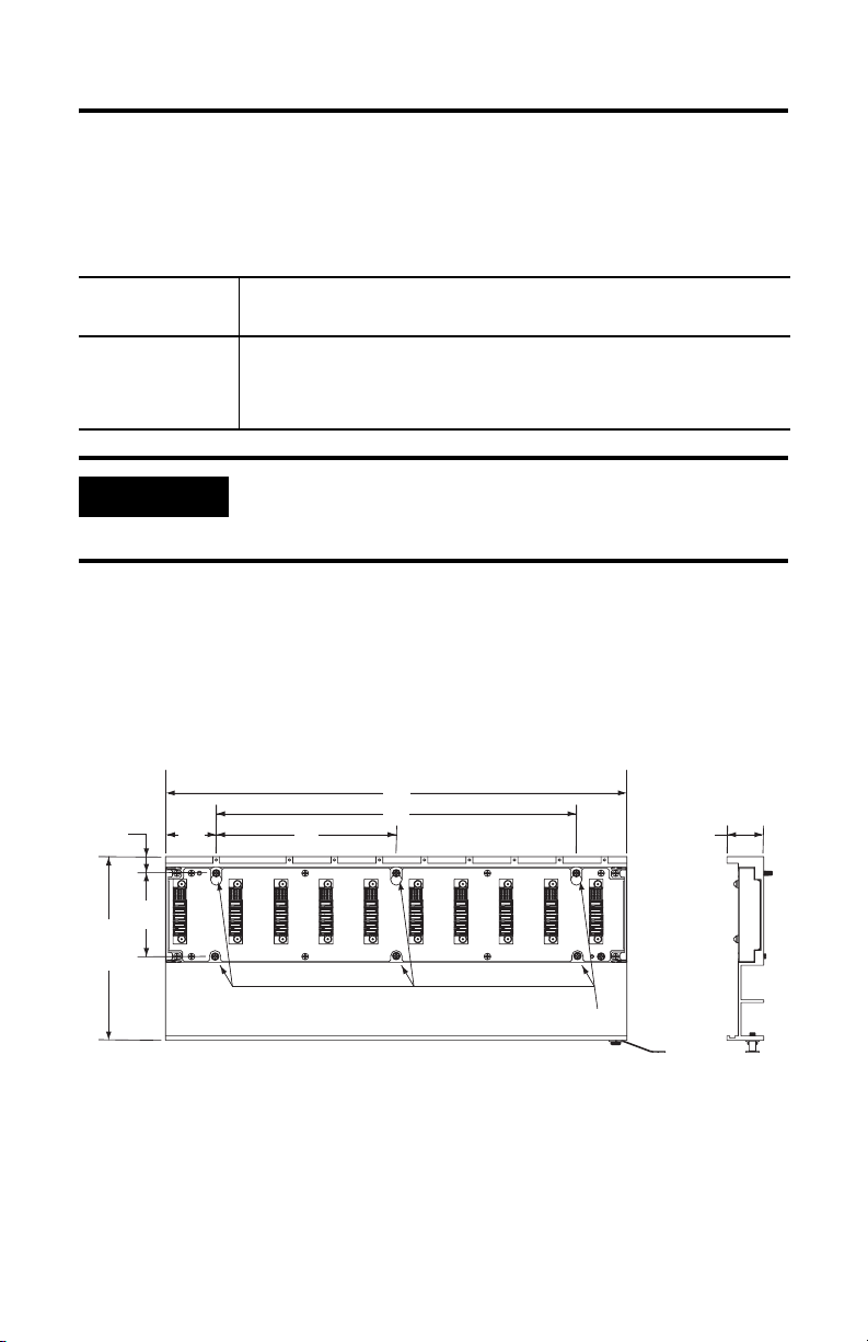
Kinetix 2000 パワーレール 53
作業を開始する前に
コンポーネントの内部や周辺の梱包材、くさび、締め金をすべて取り除いてくだ
さい。開梱後に、銘板のカタログ番号を注文書と比べてください。
Kinetix 2000 パワー・レール・ボックスの内容
ドライブ
同梱されている製品
コンポーネント
パワーレール • 1 本の編組接地ストラップ 100mm( 3.9 インチ)
• 本書(インストレーションインストラクション
(Pub. No. 2093-IN004))
重要
パワーレールとサブパネルとのボンディング状態を改善す
るには、亜鉛めっきされた(塗料が塗られていない)ス
チールでサブパネルを構成します。
寸法
以下の図と表に、Kinetix 2000 パワーレールの取付け寸法を示します。
Kinetix 2000 パワーレールの概算寸法
寸法の単位は、mm(インチ)です。
A
15.1
(0.59)
167.5
(6.59)
76.0
(2.99)
45
(1.77)
C
B
32.66
(1.29)
2093-PRS8S
M4 Mounting Screws
Pub. No. 2093-IN004A-MU-P - December 2006
Page 54

54 Kinetix 2000 パワーレール
Kinetix 2000 パワーレールの寸法
Cat. No.
2093-PRS1 1 90.0
2093-PRS2 2 130.0
2093-PRS3 3 170.0
2093-PRS4 4 210.0
2093-PRS5 5 250.0
2093-PRS7 7 330.0
2093-PRS8S 8 410.0
パワー
レール軸
A
mm
(インチ)
(3.54)
(5.12)
(6.69)
(8.27)
(9.84)
(12.99)
(16.14)
B
mm
N/A N/A
40.0
80.0
120.0
160.0
240.0
320.0
(インチ)
(1.58)
(3.15)
(4.72)
(6.30)
(9.45)
(12,60)
C
mm
N/A
N/A
N/A
N/A
120.0
160.0
(インチ)
(4.72)
(6.30)
パワーレールの取付け
Kinetix 2000 パワーレールには複数の長さのものがあります。パワーレールは、
1 つの一体型軸モジュール、複数の追加の軸モジュール、1 つのシャントモ
ジュール(Cat.No. 2093-AC05-MPx, 2093-AMPx, 2093-AM0x, 2093-ASP06)をサ
ポートします。制御信号とシステム電源を導通させるには、空いているスロット
にスロット・フィラー・モジュール(2093-PRF)を取付ける必要があります。
概算寸法
注意
これらの手順は、すでにパネルを製作し、システムのボン
ディング方法を理解していることを前提にしています。
パワーレールの接地方法およびボンディング方法に関する
詳細な手順は、『Kinetix 2000 多軸サーボドライブ ユー
ザーズマニュアル』(
Pub. No. 2093-UM001)を参照して
ください。
以下の手順に従って、Kinetix 2000 パワーレールを取付けてください。
1. エンクロージャ内のパワーレールの取付け配置を決めます。
パネル配置の推奨例については、『Kinetix 2000 多軸サーボドライブ ユー
ザーズマニュアル』(Pub. No. 2093-UM001)を参照してください。取付け
穴の寸法は図と表に記載されています。
2. パワーレールをキャビネットに取付けます。
推奨取付け具は、M4 メトリックボルトです。
Pub. No. 2093-IN004A-MU-P - December 2006
Page 55

Kinetix 2000 パワーレール 55
高周波ノイズを効果的に抑制するためのボンディング方法については、
『System Design for Control of Electrical Noise Reference Manual』(Pub. No.
GMC-RM001)を参照してください。
3. すべての取付け留め具をしっかり締めます。
4. 以下の図に示すように、編組接地ストラップを接地スタッドとボンディン
グされたキャビネット接地バスとの間に取付けます。
編組接地ストラップの取付け
Kinetix 2000 パワーレール
(図には
2093-PRS3 を示す)
ボンディングされたキャビネット
接地バス
接地グリッドまたは配電接地
パワーレール
接地スタッド
編組接地ストラップ
100mm(3.9 インチ)
Pub. No. 2093-IN004A-MU-P - December 2006
Page 56

56 Kinetix 2000 パワーレール
追加情報
アレン・ブラドリー製品に関連する追加情報については、以下の資料も参照して
ください。
内容 マニュアル名
Kinetix 2000 サーボ・ドライ
ブ・システムの取付け、構成、
起動、トラブルシューティン
グ、アプリーションに関する
情報
Kinetix 2000 軸モジュールの取
付けに関する情報
Kinetix 2000 およびシャントモ
ジュールの取付けに関する情報
Kinetix 2000 スロット・フィ
ラー・モジュールの取付けに
関する情報
ノイズによって発生するシス
テムの故障を最小限にするた
めに設計に必要な情報、例、
および技術
Kinetix モーションコントロー
ル製品の仕様、モータ / サー
ボ・ドライブ・システムの組
合わせ、およびアクセサリ
AutoCAD(DXF)図面を含む
オンライン製品選択・システ
ム構成ツール
ロックウェル・オートメー
ションから現在有効な適合宣
言書(DoC)
産産業用オートメーションの
用語と略語の用語集
Kinetix 2000 多軸サーボドラ
イブ ユーザーズマニュアル
Kinetix 2000 軸モジュール
インストレーションインスト
ラクション
Kinetix 20002000 シャントモ
ジュール インストレーショ
ンインストラクション
Kinetix 2000 スロット・フィ
ラー・モジュール インス
トレーションインストラク
ション
System Design for Control of
Electrical Noise Reference
Manual
EMC Noise Management DVD GMC-SP001
Kinetix モーションコント
ロール 選択ガイド
ロックウェル・オートメー
ションの構成および選択ツー
ルの Web サイト
ロックウェル・オートメー
ションの製品認証に関する
Web サイト
Rockwell Automation Industrial
Automation Glossary
(産業オートメーション用語
集技術用語ガイド)
Pub. No.
2093-UM001
2093-IN001
2093-IN002
2093-IN003
GMC-RM001
GMC-SG001
http://www.ab.com/e-tools/
http://www.rockwellautomation.com/
products/certification
AG-7.1
出版物を参照またはダウンロードする場合は、
http://literature.rockwellautomation.com
から行なうことができます。技術資料を
ハードコピーでお求めの場合は、お近くのロックウェル・オートメーション代理
店か営業支店までお問い合わせください。
Pub. No. 2093-IN004A-MU-P - December 2006
Page 57

Notes:
Kinetix 2000 パワーレール 57
Pub. No. 2093-IN004A-MU-P - December 2006
Page 58
当社のサポートサービス
ロックウェル・オートメーションは、製品の使用を支援するための技術情報を
Web から提供しています。http://support.rockwellautomation.com では、技術資料、
知識ベースの FA Q、テクニカルノートやアプリケーションノート、サンプルコー
ドやソフトウェア・サービス・パックへのリンク、およびこれらのツールを最大
限活用するようにカスタマイズできる MySupport 機能を探すことができます。
設置、構成、およびトラブルシューティングのさらなるテクニカル電話サポート
のために、TechConnect Support programs を提供しています。詳細は、代理店また
はロックウェル・オートメーションの支店に問い合わせるか、または
http://support.rockwellautomation.com
をご覧ください。
設置支援
設置から 24 時間以内にハードウェアモジュールに問題が発生した場合は、まず
本書に記載された情報を確認してください。また、モジュールの起動と動作を初
期支援する特別なカスタマサポート番号に連絡することもできます。
米国
米国以外 テクニカルサポートについては、地域のロックウェル・オートメー
1.440.646.3223
月曜日~金曜日、AM8:00 ~ PM5:00(東部標準時間)
ションの代理店に連絡してください。
製品の返品
ロックウェル・オートメーションでは、製造工場から出荷されるときに製品が完
全に動作することをテストしていますが、製品が機能せず返品する必要があると
きには、以下の手続きを行ってください。
米国 代理店に連絡してください。返品手続きを行なうには、代理店にカ
米国以外 返品手続きについては、地域のロックウェル・オートメーションの
スタマサポートのケース番号を知らせる必要があります(ケース番
号は上記の電話番号に問い合わせる)。
支店にお問い合わせください。
Pub. No. 2093-IN004A-MU-P - December 2006
Copyright © 2006 Rockwell Automation, Inc. All rights reserved. Printed in the U.S.A.
Page 59

설치 지침
Kinetix 2000 파워 레일
카탈로그 번호 2093-PRS1, 2093-PRS2, 2093-PRS3,
2093-PRS4, 2093-PRS5, 2093-PRS7, 2093-PRS8S
주제 쪽
이 문서에 대하여 59
중요한 사용자 정보 60
시작하기 전에 61
파워 레일 설치 62
추가 정보 64
이 문서에 대하여
이 문서는 Kinetix 2000 파워 레일 (PR) 에 대한 설치 지침을 제공합니다 . 파워
레일을 패널에 설치하는데 이 지침서를 사용하십시오 .
파워 레일은 서보 모터 또는 모션을 발생시키는 다른 장치를 제어하고 전력을
공급하는 Kinetix 2000 축 모듈에 전력 및 제어 신호를 분배합니다 . 파워 레일은
1 ~ 8 개의 축의 Kinetix 2000 모션 시스템을 포함하는 모듈을 위한 공동 마운팅
매커니즘을 제공합니다 .
전력 상승 과정 , 고장진단 정보 , Kinetix 2000 시스템과 ControlLogix,
CompactLogix 및 SoftLogix 모듈 또는 PCI 카드와의 통합에 대한 지침에 대해
서는 Kinetix 2000 다축 서보 드라이브 사용자 메뉴얼 2093-UM001 을 참조하
십시오 . 사용자 메뉴얼은 자세한 배선연결 예와 이 문서에 기술되지 않은 액세서
리와 장치의 설치 또는 제거에 대한 정보를 제공합니다 .
Publication 2093-IN004A-MU-P - 2006.12
Page 60

60 Kinetix 2000 파워 레일
중요한 사용자 정보
고체상태의 장치는 일반 전자기계 장치와는 구별되는 동작 특성을 가지고 있습니다 . 고체
상태 제어의 활용 , 설치 , 유지 관리에 대한 안전 지침 ( 각 지역 로크웰 오토메이션 판매점
또는 온라인으로 http://literature.rockwellautomation.com
SGI-1.1) 에는 고체상태 장비와 물리적 결선방식의 전자기계 장치 간의 차이점이 나와 있습
니다 . 이러한 차이점 때문에 , 그리고 또한 , 고체상태 장치가 매우 다양한 방식으로 사용되고
있기 때문에 , 이 장치를 사용하는데 책임이 있는 모든 사람들은 그 장치가 의도된 목적에
맞게 사용되도록 확실하게 해야합니다 .
로크웰 오토메이션은 어떠한 경우에도 이 장치의 사용이나 응용으로 발생하는 간접적 또는
파생적 손해에 대해 책임을 지지 않습니다 .
이 설명서에 들어 있는 예제 및 다이어그램은 설명을 위해 사용한 것입니다 . 각각의 설치 경우
마다 관련된 변수 및 전제조건들이 많기 때문에 , 로크웰 오토메이션은 예제와 다이어그램을
기초로 하여 실제로 사용한 경우에 대해서 어떠한 법적 책임 및 의무도 지지 않습니다 .
로크웰 오토메이션은 이 설명서에 설명된 정보 , 회로 , 장치 또는 소프트웨어의 사용과
관련된 특허 책임을 지지 않습니다 .
로크웰 오토메이션의 서면 허가 없이 , 이 설명서의 전체 또는 일부 내용을 복제하는 것은
금지되어 있습니다 .
이 설명서 전체에 걸쳐 , 안전을 고려해야 하는 부분에는 필요할 경우 " 주 " 를 사용하였습니다 .
에서 구할 수 있는 발행물
경고
부상 , 사망 , 재산상의 손해 또는 경제적 손실을 초래할 수
있는 위험한 환경에서 폭발을 일으킬 수 있는 행위 또는 상
황에 대한 정보를 나타냅니다 .
중요
주의
제품을 이해하고 성공적으로 사용하는데 중요한 정보를
나타냅니다 .
부상 또는 사망 , 재산 피해 및 경제적인 손실을 초래할 수
있는 상황 또는 행위에 대한 정보를 나타냅니다 . 주의는
사용자가 위험을 인식하여 이를 방지하고 , 중요성을 인식
하는데 도움을 줍니다 .
감전 사고
위험한 전압이 인가되어 있을 수 있음을 알리기 위해 , 라
벨이 장치 ( 예를 들면 , 드라이브 또는 모터 ) 의 안쪽이나
표면에 부착되어 있을 수 있습니다 .
화상 위험
제품 표면이 매우 뜨거움을 알리기 위해 , 장치 ( 예를 들면 ,
드라이브 또는 모터 ) 의 안쪽이나 표면에 라벨이 부착되어
있을 수 있습니다 .
Publication 2093-IN004A-MU-P - 2006.12
Page 61

Kinetix 2000 파워 레일 61
시작하기 전에
구성부품 주변 및 내부로부터 포장재 , 웨지 그리고 브레이스를 제거하십시오 .
포장을 푼 후 , 품목 명판 카탈로그 번호를 주문서와 대조해 보십시오 .
Kinetix 2000 파워 레일 박스 내용물
드라이브 구성요품 함께 선적
파워 레일 • 편복선 100 mm (3.9 in.) 접지 스트랩 1 개
• 이 메뉴얼 , 설치 지침 , 문서 2093-IN004.
중요
파워 레일과 서브 패널 사이의 결합력을 향상시키기 위해 ,
아연도금강판 ( 도장하지 않음 ) 으로 된 서브 패널을 설치하
십시오 .
치수
Kinetix 2000 파워 레일의 설치 치수는 아래에 그림과 표에 제시되어 있습니다 .
Kinetix 2000 파워 레일의 대략적인 치수
모든 단위 mm (in.)
A
15.1
(0.59)
167.5
(6.59)
76.0
(2.99)
45
(1.77)
2093-PRS8S
C
B
M4 Mounting Screws
32.66
(1.29)
Publication 2093-IN004A-MU-P - 2006.12
Page 62
62 Kinetix 2000 파워 레일
Kinetix 2000 파워 레일 치수
카탈로그
번호
2093-PRS1 1 90.0 (3.54) N/A N/A
2093-PRS2 2 130.0 (5.12) 40.0 (1.58) N/A
2093-PRS3 3 170.0 (6.69) 80.0 (3.15) N/A
2093-PRS4 4 210.0 (8.27) 120.0 (4.72) N/A
2093-PRS5 5 250.0 (9.84) 160.0 (6.30) N/A
2093-PRS7 7 330.0 (12.99) 240.0 (9.45) 120.0 (4.72)
2093-PRS8S 8 4 1 0 . 0 (16.14) 320.0 (12.60) 160.0 ( 6 .30)
파워 레일
축
치수 , 대략
A
mm (in.)Bmm (in.)Cmm (in.)
파워 레일 설치
Kinetix 2000 파워 레일은 여러가지 길이로 제작되어 있습니다 . 파워 레일은
하나로 통합된 축 모듈 , 추가 축 모듈 , 그리고 션트 모듈 ( 카탈로그 번호
2093-AC05-MPx, 2093-AMPx, 2093-AM0x, 및 2093-ASP06) 을 지원합니
다. 이외에도 개방 슬롯에는 제어 신호와 시스템 전력을 계속 공급하기 위한 슬롯
필러 모듈 (2093-PRF) 이 설치되어 있어야 합니다 .
주의
이 과정은 귀하가 패널을 준비하였고 귀하의 시스템을 결합
시키는 방법을 이미 알고 있다고 가정한 것입니다 .
파워 레일을 결합시키고 접지시키는 방법에 대한 자세한
지침에 대해서는 Kinetix 2000 다축 서보 드라이브 사용자
메뉴얼 2093-UM001 을 참조하십시오 .
이 과정에 따라서 Kinetix 2000 파워 레일을 설치하십시오 .
1. 보호 케이스에 파워 레일의 위치를 배치하십시오 .
패널 배치에 대한 권장사항은 , Kinetix 2000 다축 서보 드라이브 사용자
메뉴얼 2093-UM001 을 참조하십시오 . 마운팅 홀 치수는 그림과 표에
제시되어 있습니다 .
2. 파워 레일을 캐비넷에 부착하십시오 .
권장된 마운팅 하드웨어는 M4 메트릭 볼트입니다 .
Publication 2093-IN004A-MU-P - 2006.12
Page 63
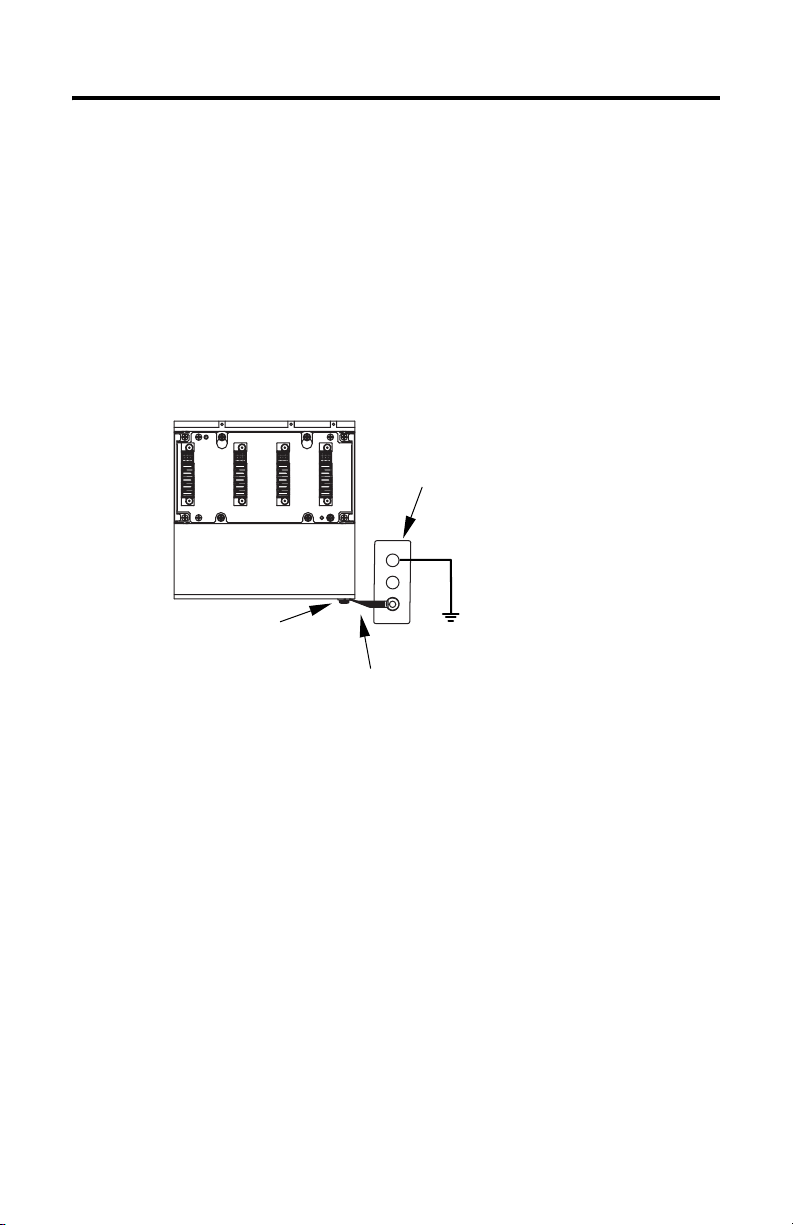
Kinetix 2000 파워 레일 63
고주파 소음을 효과적으로 감소시키는 결합 기술에 대해서는, 전기적 소음
컨트롤을 위한 시스템 디자인 참고 자료 GMC-RM001 을 참조하십시오 .
3. 모든 마운팅 파스너를 조이십시오 .
4. 다음 그림에 나타난대로 , 접지 스터드와 결합된 캐비넷 접지 사이에
편복선 접지 스트랩을 부착하십시오 .
편복선 접지 스트랩 부착
Kinetix 2000 파워 레일
(2093-PRS3 에서 나타냄 )
결합된 캐비넷
접지 버스
접지 그리드 또는 전력
파워 레일
접지 스터드
편복선 접지 스트랩
100 mm (3.9 in.)
분배 접지
Publication 2093-IN004A-MU-P - 2006.12
Page 64

64 Kinetix 2000 파워 레일
추가 정보
다음 문서에는 Allen-Bradley 제품과 관련된 추가 정보가 들어 있습니다 .
제목 이 문서를 읽으십시오 문서 번호
Kinetix 2000 서보 드라이브
시스템용 애플리케이션 ,
설치 , 컨피규레이션 , 시동
그리고 고장진단에 대한 정보
Kinetix 2000 축 모듈의
설치에 대한 정보
Kinetix 2000 과 션트
모듈의 설치에 대한 정보
Kinetix 2000 슬롯 필러 모
듈의 설치에 대한 정보
전기적 소음에 의해 발생하는
시스템 고장을 최소화하기
위해 고안된 기술 , 정보
그리고 예시
제원 , Kinetix 모션 컨트롤
제품용 액세서리 및 모터 /
서보 드라이브 시스템
컴비네이션
온라인 제품 선택과 시스템
컨피규레이션 툴, AutoCAD
(DXF) 드로잉 포함
Rockwell Automation 으로
부터 현재 지원되는 적합성
선언 (DoC) 에 대해
산업 자동화 용어와 약어에
대한 용어해설
Kinetix 2000 다축 서보
드라이브 사용자 메뉴얼
Kinetix 2000 축 모듈
설치 지침
Kinetix 2000 션트 모듈
설치 지침
Kinetix 2000 슬롯 필러
모듈 설치 지침
전기적 소음 컨트롤을
위한 시스템 디자인 참고
자료
EMC 소음 관리 DVD GMC-SP001
Kinetix 모션 컨트롤 제품
선정 가이드
Rockwell Automation
컨피규레이션과 선택 툴
웹사이트
Rockwell Automation
제품 인증 웹사이트
Rockwell Automation
산업 자동화 용어해설
2093-UM001
2093-IN001
2093-IN002
2093-IN003
GMC-RM001
GMC-SG001
http://www.ab.com/e-tools/
http://www.rockwellautomation.
com/products/certification
AG-7.1
http://literature.rockwellautomation.com
에서 문서를 보거나 다운로드할 수
있습니다 . 기술 문서의 인쇄본을 주문하려면 로크웰 오토메이션 영업 지사 또는
대리점에 연락하십시오 .
Publication 2093-IN004A-MU-P - 2006.12
Page 65

Kinetix 2000 파워 레일 65
Publication 2093-IN004A-MU-P - 2006.12
Page 66

Rockwell Automation 지원
Rockwell Automation 에서는 제품을 사용할 때 도움이 되도록 웹에 기술 정보를
제공합니다 . http://support.rockwellautomation.com
FAQ 기술 자료 , 기술 및 애플리케이션 정보 , 소프트웨어 서비스 팩 샘플 코드 및
링크 , 사용자 정의하여 이러한 도구를 활용할 수 있는 MySupport 기능 등을
찾을 수 있습니다 .
설치 , 구성 및 문제 해결에 대한 추가적인 기술 전화 지원을 원하는 경우
TechConnect Support 프로그램을 이용할 수 있습니다 . 자세한 내용은 각
지역 판매 대리점 또는 Rockwell Automation 담당자에게 문의하거나
http://support.rockwellautomation.com
을 방문하십시오 .
설치 지원
처음 하드웨어 모듈을 설치한 후 24 시간 이내에 문제가 발생하는 경우 이 설명서에
포함된 정보를 다시 확인하십시오 . 모듈을 시작하거나 실행하는 데 초기 지원이
필요한 경우 아래의 특별 고객 지원 전화를 이용할 수도 있습니다 .
미국 1.440.646.3223
월요일 - 금요일 , 오전 8 시 - 오후 5 시 ( 동부 표준시 )
미국 이외의 국가 각 지역 Rockwell Automation 담당자에게 문의하여 기술 지원을
받으십시오 .
새 제품 반환 서비스
Rockwell 에서는 공장에서 만들어진 모든 제품에 대해 테스트를 시행하여 제품이
완벽하게 작동하는지 확인합니다 . 그럼에도 불구하고 제품이 제대로 작동을 하지
않아 새 제품과 반환해야 하는 경우 아래 표를 참조하십시오 .
미국 판매 대리점에 문의하십시오 . 반환 절차를 완료하려면 판매 대리점
에 고객 지원 케이스 번호를 제공해야 합니다 . 이 번호를 받으려면
위의 전화 번호를 참조하십시오 .
미국 이외의 국가 각 지역 Rockwell Automation 담당자에게 문의하여 반환 절차를
Allen-Bradley, CompactLogix, ControlLogix, Kinetix, Rockwell Automation, SoftLogix 및 TechConnect 는
Rockwell Automation, Inc. 의 상표입니다 .
Rockwell Automation 이외의 상표는 각 상표를 소유한 회사의 재산입니다 .
밟으십시오 .
을 방문하면 기술 설명서 ,
Publication 2093-IN004A-MU-P - 2006.12
Copyright © 2006 Rockwell Automation, Inc. All rights reserved. Printed in the U.S.A.
Page 67

安装操作说明
Kinetix 2000
电源导轨
目录号 2093-PRS1、 2093-PRS2、 2093-PRS3、 2093-PRS4、
2093-PRS5、 2093-PRS7、 2093-PRS8S
主题 页码
关于本出版物
重要用户信息
开始前
安装电源导轨
其它资源
关于本出版物
该出版物提供了 Kinetix 2000 电源导轨 (PR) 的安装说明。使用这些说明将电源导轨
安装到盘柜上。
电源导轨提供电源和控制信号给 Kinetix 2000 轴模块,这些模块为伺服马达或其它
设备的生产运行提供电源并进行控制。电源导轨为包括 1 到 8 个轴的 Kinetix 2000
运行系统的模块提供一个公共安装机构。
参照 Kinetix 2000 多轴伺服驱动系统用户手册,出版物 2093-UM001,可了解通电步
骤、故障处理信息及将 Kinetix 2000 系统与 ControlLogix、CompactLogix 和 SoftLogix
模块或 PCI 卡相集成的说明。用户手册提供了详尽的接线实例,以及有关安装或拆
除本文档未提及的设备和附件的信息。
67
68
69
70
72
出版物 2093-IN004A-MU-P - 2006 年 12 月
Page 68

68 Kinetix 2000 电源导轨
重要用户信息
固态设备具有与机电设备不同的运作特性。 Safety Guidelines for the Application, Installation and
Maintenance of Solid State Controls ( 《固态控制器的应用、安装和维护安全准则》,出版号
SGI-1.1,可从当地罗克韦尔自动化销售处或者从 http://literature.rockwellautomation.com
说明了固态设备与硬连接机电设备之间的重要差别。由于存在这些区别,同时由于固态设备
的广泛应用,负责应用此设备的所有人员都必须确保仅以可接受的方式应用此设备。
对于由于使用或应用此设备而导致的任何间接或连带损失,罗克韦尔自动化在任何情况下都
不承担任何责任。
本手册中的示例和图表仅供说明之用。由于任何特定的安装都存在很多差异和要求,罗克韦
尔自动化对于依据这些示例和图表所进行的实际应用不承担任何责任或义务。
对于本手册中所述信息、电路、设备或软件之使用,罗克韦尔自动化不负担专利责任。
未经罗克韦尔自动化书面许可,任何单位或个人不得复制本手册之全部或部分内容。
在整本手册中,我们在必要的地方做出了说明,以向您告知安全注意事项。
联机获得 )
警告
指明在危险环境下可能导致爆炸进而造成人身伤害或死亡、
财产损坏或经济损失的行为或情况的信息。
重要事项
注意
指明成功应用和理解产品的关键信息。
指明可能造成人身伤害或死亡、财产损坏或经济损失的行
为或情况的信息。“注意”帮助您确定危险情况,避免发生
危险,并了解可能的后果。
触电危险
标签可贴放在设备上或者设备内 ( 如驱动器或马达 ),以警
告他人可能存在危险电压。
燃烧危险
标签可贴放在设备上或者设备内 ( 如驱动器或马达 ),以警
告他人表面温度可能很高,注意避免危险。
出版物 2093-IN004A-MU-P - 2006 年 12 月
Page 69
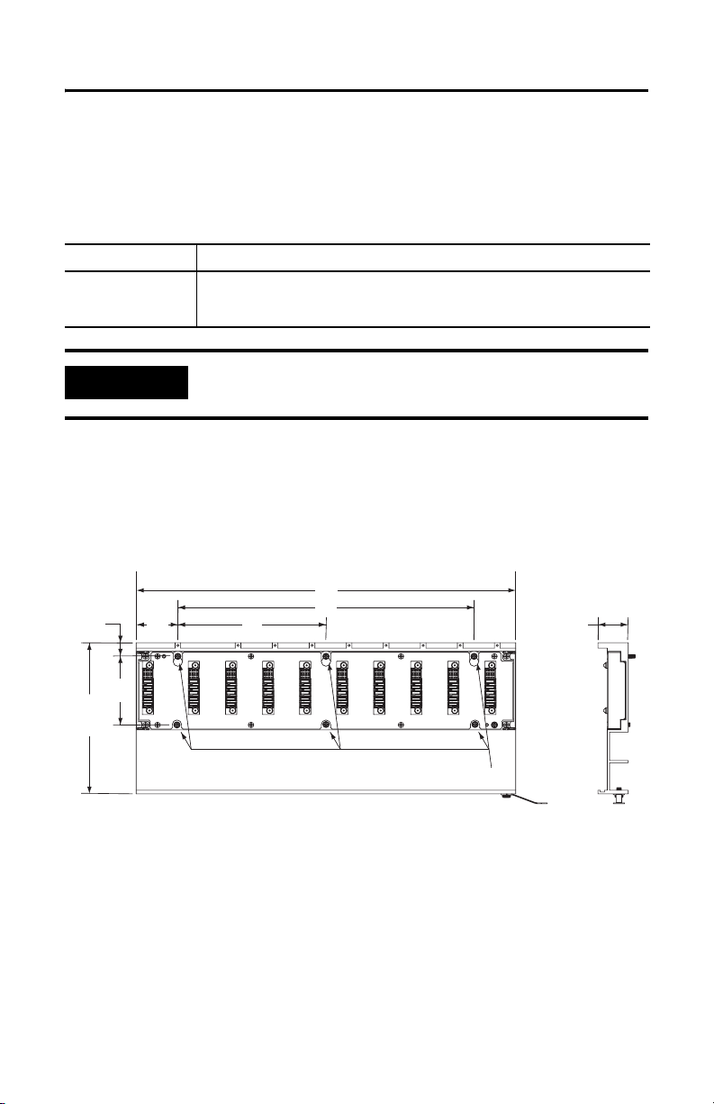
Kinetix 2000 电源导轨 69
开始前
拆除组件内部和周围的所有包装材料、楔子和吊带。拆开包装后,请对照订购单检
查货物铭牌目录号。
Kinetix 2000 电源导轨箱内容
驱动器组件 随附有
电源导轨 • 一根扎起的 100 mm (3.9 英寸 ) 的接地带
• 本手册、安装说明,出版物 2093-IN004。
重要事项
要改进电源导轨和安装板之间的连接,在镀锌 ( 不喷漆 ) 钢板
外构建安装板。
尺寸
Kinetix 2000 电源导轨的安装尺寸在下图和表格中显示。
Kinetix 2000 电源导轨近似尺寸
A
15.1
(0.59)
167.5
(6.59)
76.0
(2.99)
45
(1.77)
2093-PRS8S
C
B
M4 Mounting Screws
尺寸单位为毫米 ( 英寸 )
32.66
(1.29)
出版物 2093-IN004A-MU-P - 2006 年 12 月
Page 70

70 Kinetix 2000 电源导轨
Kinetix 2000 电源导轨尺寸
目录号
2093-PRS1 1 90.0 (3.54) N/A N/A
2093-PRS2 2 130.0 (5.12) 40.0 (1.58) N/A
2093-PRS3 3 170.0 (6.69) 80.0 (3.15) N/A
2093-PRS4 4 210.0 (8.27) 120.0 (4.72) N/A
2093-PRS5 5 250.0 (9.84) 160.0 (6.30) N/A
2093-PRS7 7 330.0 (12.99) 240.0 (9.45) 120.0 (4.72)
2093-PRS8S 8 410.0 (16.14) 320.0 (12.60) 160.0 (6.30)
电源导轨
轴
尺寸,近似
A
mm (in.)Bmm (in.)Cmm (in.)
安装电源导轨
Kinetix 2000 电源导轨有多种长度。电源导轨支持一个集成轴模块、附加轴模块和
一个分流模块 ( 目录号 2093-AC05-MPx、2093-AMPx、2093-AM0x 和 2093-ASP06)。
其它打开的插槽必须有一个填槽模块 (2093-PRF),安装用以保持控制信号和系统电
源的持续性。
注意
执行该步骤之前假定您已经准备好面板并了解如何连接
您的系统。
参照 Kinetix 2000 多轴伺服驱动系统用户手册,出版物
2093-UM001,获得关于如何将电源导轨接地和连接的详细
说明。
按照这些步骤来安装 Kinetix 2000 电源导轨。
1. 在机箱中为电源导轨安排位置。
关于面板布置建议,参照 Kinetix 2000 多轴伺服驱动系统用户手册,出版物
2093-UM001。安装孔尺寸在图上和表中均有提供。
2. 将电源导轨加装到机柜上。
推荐的安装小五金器具为 M4 米制螺栓。
出版物 2093-IN004A-MU-P - 2006 年 12 月
Page 71

Kinetix 2000 电源导轨 71
关于可以有效减少高频噪音的连接技术,参照电气噪音控制系统设计参考手
册,出版物 GMC-RM001。
3. 紧固所有安装扣件。
4. 如下列图中所示,将扎起的接地带加装到接地螺栓和连接的机柜底板之间。
加装扎起的接地带
Kinetix 2000 电源导轨
(2093-PRS3 显示 )
连接的机柜
接地总线
接地格栅或电源
电源导轨
接地螺栓
扎起的接地带
100 mm (3.9 in.)
分配底板
出版物 2093-IN004A-MU-P - 2006 年 12 月
Page 72

72 Kinetix 2000 电源导轨
其它资源
下面的文档包含关于 Allen-Bradley 产品的附加信息。
要了解 阅读该文档 发行号
关于安装、配置、起动、排
除故障以及使用 Kinetix 2000
伺服驱动系统的信息
关于安装 Kinetix 2000 轴模块
的信息
关于安装 Kinetix 2000 和分流
模块的信息
关于安装 Kinetix 2000 填槽模
块的信息
用于最大程度降低由于电气
噪音引起的系统故障的信
息、实例和技术
Kinetix 运动控制产品规范、
马达 / 伺服驱动系统系统组
合及附件
在线产品选择和系统配置工
具,包括 AutoCAD (DXF) 绘图
工具
关于自罗克韦尔自动化的当
前可用一致性声明 (DoC)
工业自动化条目和缩写术语表罗克韦尔自动化工业自动
Kinetix 2000 多轴伺服驱动
系统用户手册
Kinetix 2000 轴模块安装说
明
Kinetix 2000 分流模块安装
说明
Kinetix 2000 填槽模块安装
说明
电气噪音控制系统设计参
考手册
EMC 噪音管理 DVD 光盘
Kinetix 运动控制选择指南
罗克韦尔自动化配置和选
择工具网址
罗克韦尔自动化产品证书
网址
化术语汇编
2093-UM001
2093-IN001
2093-IN002
2093-IN003
GMC-RM001
GMC-SP001
GMC-SG001
http://www.ab.com/e-tools/
http://www.rockwellautomation.com/
products/certification
AG-7.1
可以在 http://literature.rockwellautomation.com
上查看或下载出版物。要订购技术文
档的印刷拷贝,请联络当地的罗克韦尔自动化经销商或销售代表。
出版物 2093-IN004A-MU-P - 2006 年 12 月
Page 73

注意事项:
Kinetix 2000 电源导轨 73
出版物 2093-IN004A-MU-P - 2006 年 12 月
Page 74

罗克韦尔自动化支持
罗克韦尔自动化在网站上提供可帮助您使用其产品的技术信息。您可以在
http://support.rockwellautomation.com
技术和应用程序说明、范例代码以及指向软件服务包的链接,另外还提供一项
MySupport 功能,您可以通过该功能执行自定义设置,从而最优利用这些工具。
为了提供有关安装、配置和故障排除的更高一级的电话支持,我们提供了
TechConnect Support 计划。有关更多信息,请联系当地经销商或罗克韦尔自动化
代表,或者访问 http://support.rockwellautomation.com
安装帮助
如果您在安装 24 小时以内遇到硬件模块问题,请查看本手册中提供的信息。您也
可以拨打客户支持专线获得重要帮助,以修复模块问题并使之运行。
美国
美国以外地区 有关任何技术支持问题,请联系当地罗克韦尔自动化代表。
1.440.646.3223
周一 – 周五, 8am – 5pm EST
新产品退货
Rockwell 会对其所有产品进行测试,以保证其产品在出厂时能够充分运作。但
是,如果您的产品不能使用,则可能需要退货。
美国 联系当地经销商。您必须向经销商提供客户支持帐户编号 ( 参见上面
的电话号码获取一个 ),以便完成退货程序。
美国以外地区 请联系当地罗克韦尔自动化代表,了解退货手续。
上找到技术手册、常见问题解答知识库、
。
Allen-Bradley、CompactLogix、ControlLogix、 Kinetix、 Rockwell Automation、 SoftLogix 和 TechConnect 都是罗克韦尔自动化的
商标。
不属于罗克韦尔自动化的商标是其它相应公司的财产。
出版物 2093-IN004A-MU-P - 12 月 2006
© 2006 年罗克韦尔自动化版权所有,保留一切权利。美国印刷。
Page 75

75
Publication 2093-IN004A-MU-P - December 2006
Page 76

Rockwell Automation Support
Rockwell Automation provides technical information on the Web to assist you in using its
products. At http://support.rockwellautomation.com
knowledge base of FAQs, technical and application notes, sample code and links to software
service packs, and a MySupport feature that you can customize to make the best use of these
tools.
For an additional level of technical phone support for installation, configuration, and
troubleshooting, we offer TechConnect Support programs. For more information, contact
your local distributor or Rockwell Automation representative, or visit
http://support.rockwellautomation.com
.
Installation Assistance
If you experience a problem with a hardware module within the first 24 hours of installation,
please review the information that's contained in this manual. You can also contact a special
Customer Support number for initial help in getting your module up and running.
, you can find technical manuals, a
United States 1.440.646.3223
Outside United
States
Monday – Friday, 8am – 5pm EST
Please contact your local Rockwell Automation representative for any
technical support issues.
New Product Satisfaction Return
Rockwell tests all of its products to ensure that they are fully operational when shipped from
the manufacturing facility. However, if your product is not functioning, it may need to be
returned.
United States Contact your distributor. You must provide a Customer Support case number
Outside United
States
Allen-Bradley, CompactLogix, Rockwell Automation, TechConnect, SLC, and SLC 500 are trademarks of Rockwell Automation, Inc.
Trademarks not belonging to Rockwell Automation are the property of their respective companies.
(see phone number above to obtain one) to your distributor in order to
complete the return process.
Please contact your local Rockwell Automation representative for return
procedure.
Publication 2093-IN004A-MU-P - December 2006
Copyright © 2006 Rockwell Automation, Inc. All rights reserved. Printed in Korea.
 Loading...