

Page 1

Installation Instructions
Kinetix 2000 Shunt Module
Catalog Number 2093-ASP06
Topic Page
About This Publication 1
Important User Information 2
Before You Begin 3
Installing a Kinetix 2000 Shunt Module 3
Additional Resources 8
About This Publication
This publication provides basic information for installing a shunt module on a Kinetix 2000
power rail.
Use this document with the Kinetix 2000 Axis Module Installation Instructions, publication
2093-IN001, to install a Kinetix 2000 drive system.
Refer to the Kinetix 2000 User Manual, publication 2093-UM001, for power up procedures,
troubleshooting information, and instructions on integrating a Kinetix 2000 system with
ControlLogix, CompactLogix, and SoftLogix modules or PCI cards. The user manual
provides detailed wiring examples, and information about installing or removing equipment
and accessories not described in this document.
Publication 2093-IN002A-EN-P - December 2006
Page 2
2 Kinetix 2000 Shunt Module
Important User Information
Solid state equipment has operational characteristics differing from those of electromechanical equipment.
Safety Guidelines for the Application, Installation and Maintenance of Solid State Controls (publication SGI-1.1
available from your local Rockwell Automation sales office or online at http://literature.rockwellautomation.com
describes some important differences between solid state equipment and hard-wired electromechanical devices.
Because of this difference, and also because of the wide variety of uses for solid state equipment, all persons
responsible for applying this equipment must satisfy themselves that each intended application of this
equipment is acceptable.
In no event will Rockwell Automation, Inc. be responsible or liable for indirect or consequential damages
resulting from the use or application of this equipment.
The examples and diagrams in this manual are included solely for illustrative purposes. Because of the many
variables and requirements associated with any particular installation, Rockwell Automation, Inc. cannot assume
responsibility or liability for actual use based on the examples and diagrams.
No patent liability is assumed by Rockwell Automation, Inc. with respect to use of information, circuits,
equipment, or software described in this manual.
Reproduction of the contents of this manual, in whole or in part, without written permission of Rockwell
Automation, Inc., is prohibited.
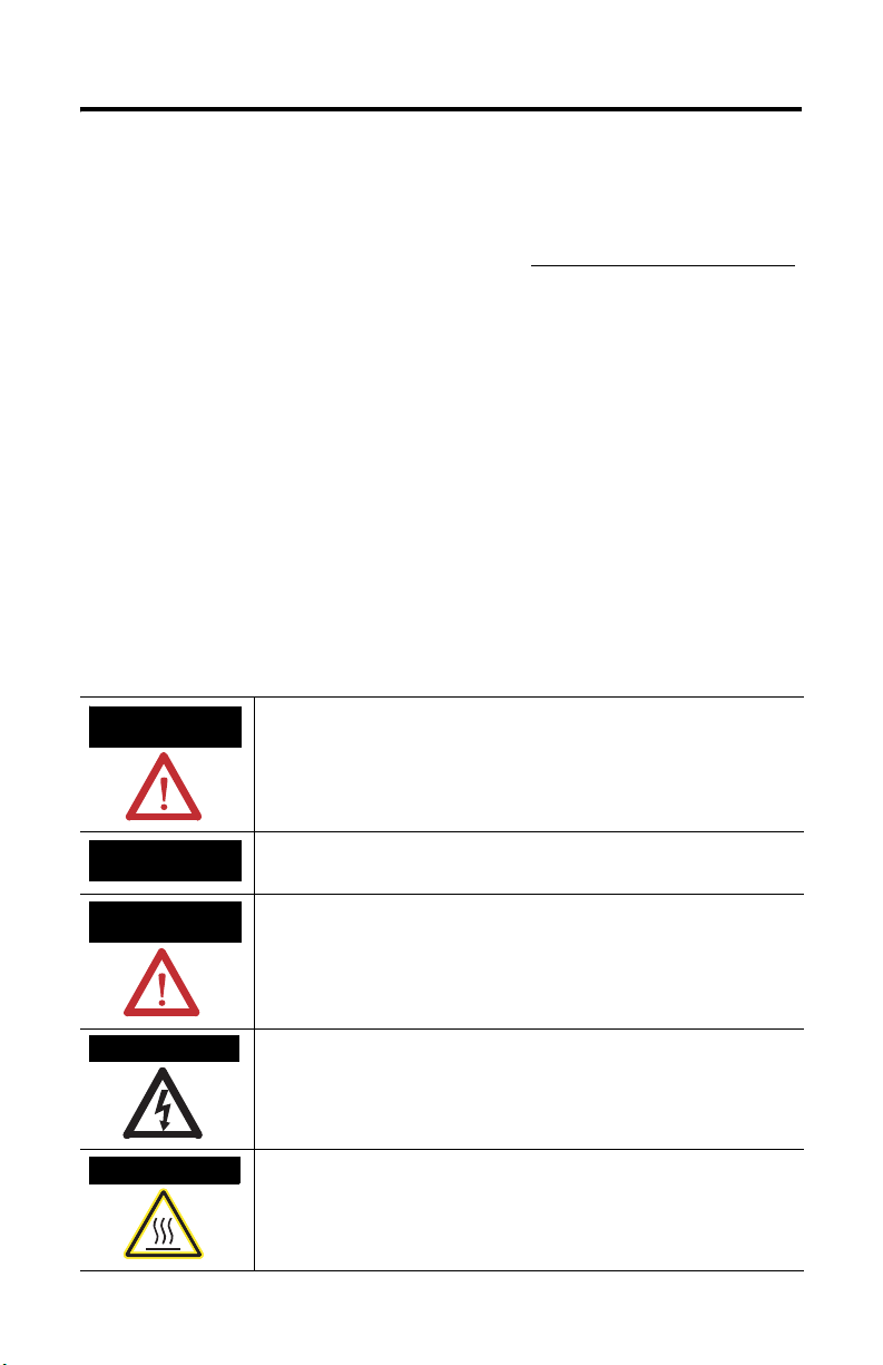
Throughout this manual, when necessary, we use notes to make you aware of safety considerations.
)
WARNING
Identifies information about practices or circumstances that can cause
an explosion in a hazardous environment, which may lead to personal
injury or death, property damage, or economic loss.
IMPORTANT
ATTENTION
Identifies information that is critical for successful application and
understanding of the product.
Identifies information about practices or circumstances that can lead to
personal injury or death, property damage, or economic loss. Attentions
help you to identify a hazard, avoid a hazard, and recognize the
consequences.
SHOCK HAZARD
Labels may be on or inside the equipment, for example, a drive or
motor, to alert people that dangerous voltage may be present.
BURN HAZARD
Labels may be on or inside the equipment, for example, a drive or
motor, to alert people that surfaces may reach dangerous temperatures.
Publication 2093-IN002A-EN-P - December 2006
Page 3
Kinetix 2000 Shunt Module 3
Before You Begin
Remove all packing material, wedges, and braces from within and around the components.
After unpacking, check the item name-plate catalog number against the purchase order.
Kinetix 2000 Drive Component Box Contents
Drive Component Ships With
Shunt module • Wiring plug for an external shunt resistor (RC).
• Wiring plug for the thermal switch (TS).
• This manual, Installation Instructions, publication 2093-IN002.
Installing a Kinetix 2000 Shunt Module
These procedures assume you have mounted your power rail, integrated axis module (IAM),
and axis modules (AM). Power rails accommodate one IAM and up to seven AMs, in addition
to a shunt module. Install a slot filler in any slot not occupied by axis modules or a shunt
module.
For installation instructions regarding equipment and accessories not included here, refer to
the instructions that came with those products.
WARNING
ATTENTION
To avoid the hazard of electrical shock, perform all mounting and wiring of
modules (IAM, AM, shunt module, or slot filler) and the power rail before you
apply power. Once power is applied, connector terminals may have voltage
present even when not in use.
Plan the installation of your system so that you can perform all cutting,
drilling, tapping, and welding with the system removed from the enclosure.
Because the system is of the open type construction, be careful to keep any
metal debris from falling into it. Metal debris or other foreign matter can
become lodged in the circuitry, which can result in damage to components.
Publication 2093-IN002A-EN-P - December 2006
Page 4

4 Kinetix 2000 Shunt Module
Determine Mounting Order
Mount a shunt module in the order described below, and as shown in the figure.
IMPORTANT
Mount the shunt module to the right of any axis modules (IAM or AM).
However, the eight-axis power rail (2093-PRS8S) requires the shunt module
be mounted in the rightmost slot.
Module Mounting Order
Highest
Integrated Axis
Module
2093-AC05-MP5
Seven-axis Power Rail Module 2093-PRS7 is shown.
Power Utilization or Amp Rating Lowest
Axis
Module
2093-AM01
Axis
Module
2093-AMP2
Axis
Module
2093-AMP2
Shunt
Module
2093-ASP06
Slot Filler
Module
2093-PRF
WARNING
To avoid personal injury due to electrical shock, place a slot filler module
(catalog number 2093-PRF) in all empty slots on the power rail.
An unoccupied slot in the power rail will disable the Kinetix 2000 system, but
control ac power will continue to be applied to the power rail.
Publication 2093-IN002A-EN-P - December 2006
Page 5

Kinetix 2000 Shunt Module 5
Mount the Shunt Module
Follow these steps to mount a Kinetix 2000 shunt module on the power rail.
IMPORTANT
The shunt module is mounted to the right of the last AM, except the
2093-PRS8S power rail requires it be mounted in the last slot.
Do not mount the shunt module on a power rail with a follower IAM in a
common bus application. The follower IAM will disable an external or
rail-mounted shunt module.
ATTENTION
To avoid damage to the pins located on the back of each module and to make
sure that module pins mate properly with the power rail, install modules as
shown below.
The power rail must be mounted with the connectors in an upright or vertical
orientation to the panel. This provides proper cooling of the modules. Do not
mount modules if the power rail is not within 3° of vertical.
1. Align the module locking screw with its corresponding slot on the power rail.
2. Push the module straight forward, by applying force at the top and bottom edges of
the front cover.
The module is fully seated when each locking clip snaps into the bottom of the power
rail, and the locking screw boss is flush at the top of the power rail.
Locking Screws
Top Front View of
IAM
(2093-AC05-MPx)
Top Front View of
Double-wide AM (2093-AM0x)
Single-wide AM (2093-AMPx)
3. Torque mounting screw to 0.7 Nm (6 lb-in).
Publication 2093-IN002A-EN-P - December 2006
Locking clips at bottom of
module are not visible.
Shunt module (2093-ASP06) and
slot filler (2093-PRF) are not shown.
Page 6

6 Kinetix 2000 Shunt Module
Shunt Module Connector Data
The internal shunt resistor (15 Ohm, 50 W) is the default setting for the shunt module.
Jumpers are factory installed from TS-1 to TS-2 and from RC-1 to RC-2 to make this default
selection.
Connectors on the shunt module are supplied with removable wiring plugs.
Shunt Module Connectors and Pinouts
Designator Description Connector Pin Signal
TS External passive shunt module
thermal switch connections
Two position
connector housing
RC External resistor connection Three-position
Internal shunt connection 2 INT
connector housing
External collector connection 3 COL
(1)
Jumper is factory installed between these TS pins to select the internal thermal switch.
(2)
Jumper is factory installed between these RC pins to select the internal shunt resistor.
Shunt Module Connectors and Indicators
1TS1
2 TS2
1 DC+
(1)
(1)
(2)
(2)
External Thermostat
(TS) Connector
External Shunt Resistor
(RC) Connector
TS1
TS2
DC+
INT
COL
Publication 2093-IN002A-EN-P - December 2006
Shunt Module, Front View
(2093-ASP06)
Power Fault LED
Over-temp Fault LED
Bus Status LED
Page 7

Wire should be copper with 75 °C (167 °F) minimum rating.
Kinetix 2000 Shunt Module 7
ATTENTION
IMPORTANT
To avoid personal injury and/or equipment damage, make sure installation
complies with specifications regarding wire types, conductor sizes, branch
circuit protection, and disconnect devices. The National Electrical Code
(NEC) and local codes outline provisions for safely installing electrical
equipment.
To avoid personal injury and/or equipment damage, make sure motor
power connectors are used for connection purposes only. Do not use them
to turn the unit on and off.
To avoid personal injury and/or equipment damage, make sure shielded
power cables are grounded to prevent potentially high voltages on the
shield.
NEC and local electrical codes take precedence over the values and
methods provided.
Publication 2093-IN002A-EN-P - December 2006
Page 8

Additional Resources
The following documents contain additional information concerning related Allen-Bradley
products.
You can view or download publications at http://literature.rockwellautomation.com
. To
order paper copies of technical documentation, contact your local Rockwell Automation
distributor or sales representative.
For Read This Document Publication Number
Information on installing, configuring,
startup, troubleshooting, and
applications for your Kinetix 2000 servo
drive system
Information on the installation of your
Kinetix 2000 axis modules
Information on the installation of your
Kinetix 2000 slot filler module
Information on the installation of your
Kinetix 2000 power rail
Information, examples, and techniques
designed to minimize system failures
caused by electrical noise
Specificatio ns, motor/servo-drive s ystem
combinations, and accessories for
Kinetix motion control products
Online product selection and system
configuration tools, including AutoCAD
(DXF) drawings
For declarations of conformity (DoC)
currently available from Rockwell
Automation
A glossary of industrial automation
terms and abbreviations
Kinetix 2000 User Manual 2093-UM001
Kinetix 2000 Axis Module
Installation Instructions
Kinetix 2000 Slot Filler Module
Installation Instructions
Kinetix 2000 Power Rail
Installation Instructions
System Design for Control of
Electrical Noise Reference
Manual
Kinetix Motion Control
Selection Guide
Rockwell Automation
Configuration and Selection
Tools website
Rockwell Automation Product
Certification website
Rockwell Automation
Industrial Automation Glossary
2093-IN001
2093-IN003
2093-IN004
GMC-RM001
GMC-SG001
http://www.ab.com/e-tools/
http://www.rockwellautomatio
n.com/products/certification
AG-7.1
Allen-Bradley, CompactLogix, ControlLogix, Kinetix, Rockwell Automation, and SoftLogix are trademarks of Rockwell Automation, Inc.
Trademarks not belonging to Rockwell Automation are the property of their respective companies.
Publication 2093-IN002A-EN-P - December 2006
Copyright © 2006 Rockwell Automation, Inc. A ll rights reserved. Printed in t he U.S.A.
 Loading...