

Page 1
Installation Instructions
Kinetix 2000 Integrated Axis Module and
Axis Module
Catalog Numbers 2093-AC05-MP1, 2093-AC05-MP2, 2093-AC05-MP5, 2093-AMP1,
2093-AMP2, 2093-AMP5, 2093-AM01, 2093-AM02
Topi c Page
Important User Information 2
Before You Begin 3
Installing a Kinetix 2000 Drive 3
IAM and AM Connector Data 7
Wiring Requirements 12
Motor Overload Protection 14
Additional Resources 15
About the Kinetix 2000 Drives
The Kinetix® 2000 integrated axis module (IAM) and up to seven axis modules (AM) mount on
the Bulletin 2093 power rail and provide power and control for up to eight servo motors.
Refer to the Kinetix 2000 Multi-axis Servo Drives User Manual, publication 2093-UM001
detailed information on wiring, applying power, troubleshooting, and integration with
ControlLogix®, CompactLogix™, and SoftLogix™ controller platforms.
, for
Page 2
2 Kinetix 2000 Multi-axis Servo Drives
IMPORTANT
Important User Information
Read this document and the documents listed in the additional resources section about installation, configuration, and operation of
this equipment before you install, configure, operate, or maintain this product. Users are required to familiarize themselves with
installation and wiring instructions in addition to requirements of all applicable codes, laws, and standards.
Activities including installation, adjustments, putting into service, use, assembly, disassembly, and maintenance are required to be
carried out by suitably trained personnel in accordance with applicable code of practice.
If this equipment is used in a manner not specified by the manufacturer, the protection provided by the equipment may be impaired.
In no event will Rockwell Automation, Inc. be responsible or liable for indirect or consequential damages resulting from the use or
application of this equipment.
The examples and diagrams in this manual are included solely for illustrative purposes. Because of the many variables and
requi rements associ ated wit h any pa rticu lar ins tallat ion, Roc kwell Au tomati on, Inc. cannot assume respon sibili ty or li abilit y for actual
use based on the examples and diagrams.
No patent liability is assumed by Rockwell Automation, Inc. with respect to use of information, circuits, equipment, or software
described in this manual.
Reproduction of the contents of this manual, in whole or in part, without written permission of Rockwell Automation, Inc., is
prohibited.
Throughout this manual, when necessary, we use notes to make you aware of safety considerations.
WARNIN G: Identifies information about practices or circumstances that can cause an explosion in a hazardous
environment, which may lead to personal injury or death, property damage, or economic loss.
ATTENTION: Identifies information about practices or circumstances that can lead to personal injury or death,
property damage, or economic loss. Attentions help you identify a hazard, avoid a hazard, and recognize the
consequence.
Identifies information that is critical for successful application and understanding of the product.
Labels may also be on or inside the equipment to provide specific precautions.
SHOCK HAZARD: Labels may be on or inside the equipment, for example, a drive or motor, to alert people that
dangerous voltage may be present.
BURN HAZARD: Labels may be on or inside the equipment, for example, a drive or motor, to alert people that
surfaces may reach dangerous temperatures.
ARC FLASH HAZARD: Labels may be on or inside the equipment, for exampl e, a motor control center, to alert
people to potential Arc Flash. Arc Flash will cause severe injury or death. Wear proper Personal Protective
Equipment (PPE). Follow ALL Regulatory requirements for safe work practices and for Personal Protective
Equipment (PPE).
Rockwell Automation Publication 2093-IN001B-EN-P - July 2013
Page 3

Kinetix 2000 Multi-axis Servo Drives 3
TIP
Before You Begin
Remove all packing material, wedges, and braces from within and around the components. After
unpacking, check the catalog number on the name-plate against the purchase order.
Parts List
Drive component Ships With
• Wiring plugs for main AC input power (IPD), control AC input power (CPD),
Integrated axis module (IAM)
contactor enable relay (CED), motor power (MP), and motor brake (BC)
• These installation instructions, publication 2093-IN001
Axis module (AM)
The motor feedback connector kit (catalog number 2090-K2CK-D15M) and auxiliary feedback
and I/O connector kit (catalog number 2090-K2CK-COMBO) are not provided. Refer to the
Kinetix Motion Accessories Specifications Technical Data, publication GMC-TD004
information.
• Wiring plugs for motor power (MP) and motor brake (BC)
• These installation instructions, publication 2093-IN001
, for more
Installing a Kinetix 2000 Drive
These procedures assume you have prepared your panel and understand how to bond your
system. For installation instructions regarding equipment and accessories not included here, refer
to the instructions that came with those products.
ATTENTION: To avoid the hazard of electrical shock, perform all mounting and wiring of the IAM,
AM, shunt, and slot filler module, and the Bulletin 2093 power rail before you apply power. Once
power is applied, connector terminals can have voltage present even when not in use.
ATTENTION: Plan the installation of your system so that you can perform all cutting, drilling,
tapping, and welding with the system removed from the enclosure. Because the system is of the
open type construction, be careful to keep any metal debris from falling into it. Metal debris or
other foreign matter can become lodged in the circuitr y and result in damage to components.
Rockwell Automation Publication 2093-IN001B-EN-P - July 2013
Page 4
4 Kinetix 2000 Multi-axis Servo Drives
IMPORTANT
IMPORTANT
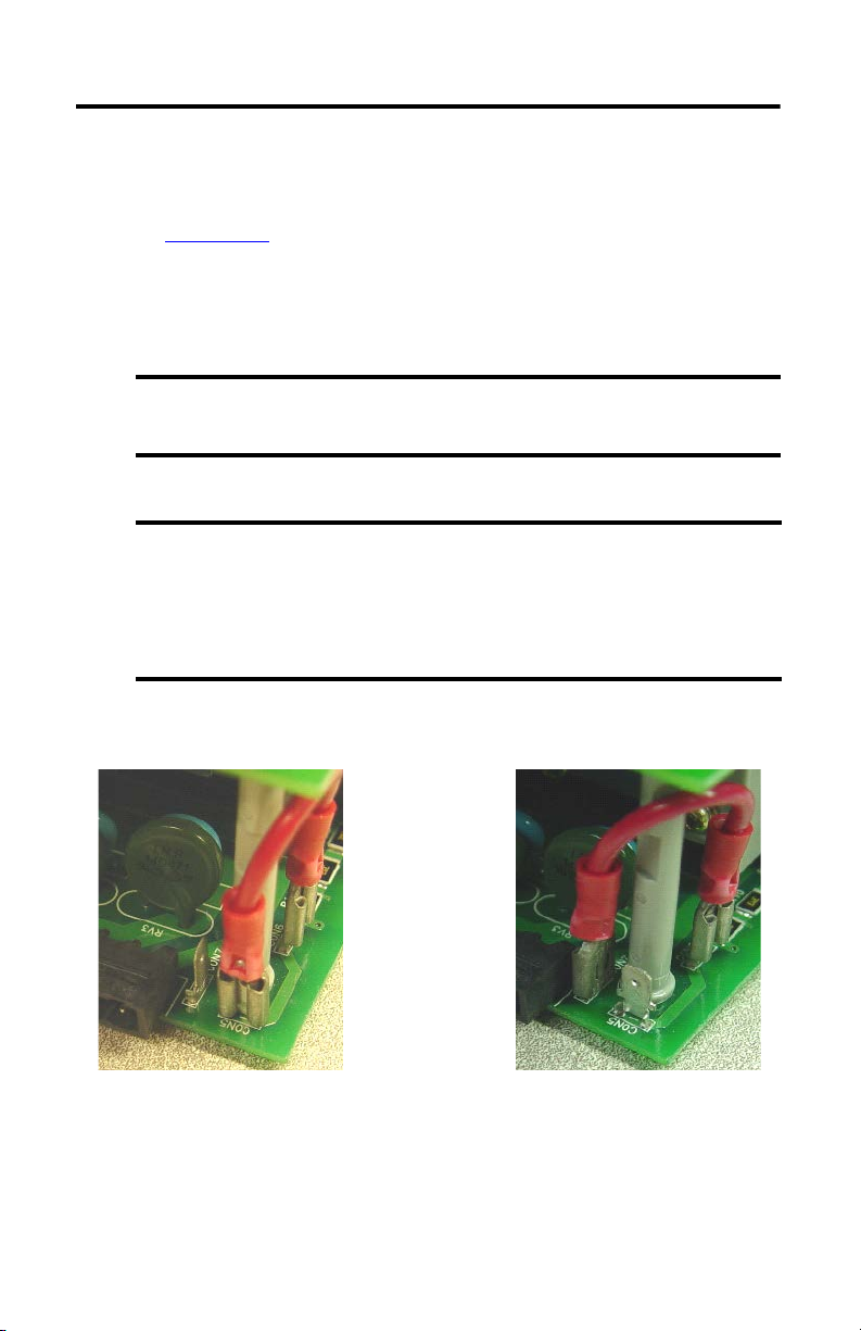
Ungrounded Configuration
CON7 to CON6
Grounded Configuration
CON5 to CON 6 (default se tting)
Set the IAM Ground Jumper for the Power Grounding Configuration
Setting the ground jumper is necessary only when using an ungrounded or high-impedance
grounded power configuration. Refer to the Kinetix 2000 Multi-axis Servo Drives User Manual,
publication 2093-UM001
Follow these steps to set the ground jumper for ungrounded or high-impedance grounded power
configurations.
1. Remove the front panel on your IAM module.
2. Move the jumper wire to connect CON6 to CON7.
, for diagrams illustrating grounded and ungrounded input power.
Disconnect all headers from the electrical connectors, and the SERCOS fiber-optic
cables on the IAM module, before attempting to remove the front panel.
A jumper wire and the grounding connections (CON5, CON6, and CON7) are on the
lower front of the power converter (leftmost) board, below the input power (IPD)
connector.
The factory default configuration (for grounded power) has the jumper installed
between CON5 and CON6.
3. Replace the IAM module front panel.
You are now ready to mount the IAM module on the power rail.
Rockwell Automation Publication 2093-IN001B-EN-P - July 2013
Page 5
Kinetix 2000 Multi-axis Servo Drives 5
IMPORTANT
Power Utilization or Amp Rating Lowest
Integrated Axis Module
2093-AC05-MP5
Axis Module
2093-AM01
Axis Modules
2093-AMP2
2093-PRS7 Seven-axis Power Rail
Highest
Shunt Module
2093-ASP06
Slot Filler
2093-PRF
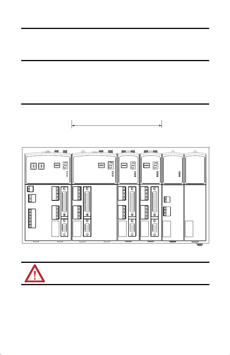
Determine Mounting Order
Mount axis modules in the order (left to right) shown in the figure.
The integrated axis module (IAM) must be positioned in the leftmost slot on the power rail,
followed by axis modules (AM).
Mount axis modules from left to right starting with the highest power utilization.
The shunt module is mounted to the right of the last AM module. The only exception is the
eight-axis power rail (catalog number 2093-PRS8S) that requires the shunt module mounted
in the rightmost slot.
Module Mounting Order
ATTENTION: To avoid personal injury due to electrical shock, place a 2 093-PRF slot filler module in
all empty slots on the power rail. Any power rail connector without a module disables the
Kinetix 2000 drive system; however, control power is still present.
Rockwell Automation Publication 2093-IN001B-EN-P - July 2013
Page 6

6 Kinetix 2000 Multi-axis Servo Drives
IMPORTANT
2093-AM0x
Double-wide
AM Module
Locki ng Screws
2093-AC05-MPx
IAM Module
Locking clips at bottom of
module are not visible.
Shunt module (2093-ASP06) and
slot filler (2093-PRF) are not shown.
2093-AMPx
Single-wide
AM Module
Mount a Module
Follow these steps to mount an axis module on the Kinetix 2000 power rail.
The IAM module must be positioned in the leftmost slot of the power rail, followed by AM
modules in descending order of power utilization.
ATTENTION: To avoid damage to pins on the back of each module, and to make sure that module
pins mate properly with the power rail, install modules as shown below.
ATTENTION: The power rail must be mounted with the connectors in an upright or vertical
orientation to the panel. This provides proper cooling of the modules. Do not mount modules if the
power rail is not within 3° of vertical.
1. Align the module locking screw with its corresponding slot on the power rail.
2. Push the module straight forward, by applying force at the top and bottom edges of the
front cover.
The module is fully seated when each locking clip snaps into the bottom of the power
rail and the locking screw boss is flush at the top of the power rail.
3. Torque mounting screw to 0.7 N•m (6.0 lb•in).
Rockwell Automation Publication 2093-IN001B-EN-P - July 2013
Page 7

Kinetix 2000 Multi-axis Servo Drives 7
Integrated Axis Module, Front View
(2093-AC05-MPx is shown)
Mounting Screw
DPI Connector
Sercos Node
Address Switches
Contactor Enable
(CED) Connector
Control Power
(CPD) Connector
Main Power
(IPD) Connector
Motor Brake
(BC) Connector
Motor Power
(MP) Connector
Mounting Tabs
Sercos Receive (Rx) Connector
Sercos Transmit (Tx) Connector
Sercos Baud Rate and
Optical Power Switches
Seven-segment Status Indicator
Drive Status
COMM Status
Bus Status
I/O and Machine
Feedback (IOD/AF) Connector
Motor Feedback
(MF) Connector
Axis Module, Front View
(2093-AM0x is shown)
Sercos Receive (Rx) Connector
Sercos Transmit (Tx) Connector
Sercos Baud Rate and
Optical Power Switches
Seven-segment Status Indicator
Drive Status
COMM St atus
Bus Status
I/O and Auxiliary Feedback
(IOD/AF) Connector
Motor Feedback
(MF) Connector
Mounting Screw
Motor Brake
(BC) Connector
Motor Power
(MP) Connector
Mounting Tabs
IAM and AM Connector Data
Use these illustrations to identify the IAM and AM module connectors and indicators.
Integrated Axis Module Connectors and Indicators
Axis Module Connectors and Indicators
Rockwell Automation Publication 2093-IN001B-EN-P - July 2013
Page 8

8 Kinetix 2000 Multi-axis Servo Drives
IMPORTANT
Connector Descriptions
Designator Description Connector
BC Motor brake 4-position plug/header
(1)
CED
(1)
CPD
(1)
DPI
IOD/AF User I/O (drive) and auxiliary feedback 44-pin high-density D-shell (female)
(1)
IPD
MF Motor feedback 15-pin high-density D-shell (female)
MP Motor power 4-position plug/header
Tx and Rx SERCOS transmit and receive SERCOS fiber-optic (2)
(1) Connector is only on integrated axis modules (catalog numbers 2093-AC05-MPx).
Contactor enable 2-position plug/header
Control input power (drive) 2-position plug/header
Drive peripheral interface (factor y use only) 8-pin mini-DIN
230V AC input power (drive) and DC bus 6-position plug/header
Contactor Enable and Power Connector Pinouts
These connectors are supplied with removable wiring plugs. The pins are numbered
consecutively from top to bottom.
These connectors are available only on integrated axis modules (catalog numbers
2093-AC05-MPx).
Contactor Enable (CED) Connector
CED Pin Description Signal
1
2 CONT EN-
Relay-driven dry contact used in the safety string for a three-phase power
contactor.
Control Power (CPD) Connector
CPD Pin Description Signal
1 Control power VAC input line 1 CTRL 1
2 Control power VAC input line 2 CTRL 2
Rockwell Automation Publication 2093-IN001B-EN-P - July 2013
CONT EN+
Page 9

Kinetix 2000 Multi-axis Servo Drives 9
Main Power and DC Bus (IPD) Connector
IPD Pin Description Signal
1
2 L2
3 L3
4 Chassis ground
5
6 DC-
(1) Not use d with single-phase power.
Single- or three-phase input power (230V AC)
An integral, unregulated power supply, consisting of AC line, three-phase bridge
rectifier, and filter capacitors
L1
DC+
(1)
Motor Power and Brake Connector Pinouts
These connectors are supplied with removable wiring plugs and are keyed to prevent incorrect
insertion. The pins are numbered consecutively from top to bottom.
Motor Brake Control (BC) Connector
BC Pin Description Signal
1 +24V brake power (from LIM or customer supplied) PWR
2
3 MBRK-
4 Motor brake common COM
Motor brake connections
MBRK+
Motor Power (MP) Connector
MP Pin Description Signal
1
2V
3W
4 Chassis ground
Three-phase motor power
Rockwell Automation Publication 2093-IN001B-EN-P - July 2013
U
Page 10

10 Kinetix 2000 Multi-axis Servo Drives
IMPORTANT
I/O Connector Pinouts
These connections require customer-supplied connectors.
IAM and AM I/O and Auxiliary Feedback 44-pin (IOD/AF) Connector
IOD/AF
Description Signal
Pin
1 Reserved – 23 Registration 2 REG2
2 Reserved – 24 24V power to registration 24V_REG
3 Reserved – 25 Registration common 24VCOM_REG
4 Reserved – 26 Registration 1 REG1
5 Reserved – 27 24V power to registration 24V_REG
6 Reserved – 28 24V common 24VCOM
7 Reserved – 29 Over travel negative input OT-
8 Reserved – 30 24V power output 24V PWR
9 Reserved – 31 Cosine/negative input B COSINE-/B-
10 Reserved – 32 Cosine/positive input B COSINE+/B+
11 Reserved – 33 Sine/negative input A SINE-/A-
12 Reserved – 34 Sine/positive input A SINE+/A+
IOD/AF
Description Signal
Pin
(2)
(2)
(2)
(2)
(2)
(2)
(2)
(2)
(1)
(1)
(1)
(1)
13 Reserved – 35 Reserved –
(2)
14 Reserved – 36 24V common 24VCOM
15 Reserved – 37 Overtravel positive input OT+
16 Data/index negative input DATA- / I-
17 Data/index positive input DATA+ / I+
18 Encoder 5V power supply EPWR_5V
19 Encoder common ECOM
20 Encoder 9V power supply EPWR_9V
(1)
(1)
41 24V power output 24VPWR
(1)
(1)
39 24V common 24VCOM
40 Home input HOME
42 24V common 24VCOM
38 24V power output 24VPWR
(1)
21 Reserved – 43 Enable ENABLE
22 Registration common 24VCOM_REG
(2)
44 24V power output 24VPWR
(2)
(2)
(2)
(2)
(2)
(2)
(2)
(2)
(1) Machine (auxiliary) feedback.
(2) User I/O.
+24V_PWR and +24V_COM are a 24V DC power source used only to power inputs on the
44-pin IOD/AF connector.
Rockwell Automation Publication 2093-IN001B-EN-P - July 2013
Page 11

IAM and AM Motor Feedback 15-pin (MF) Connector
15-pin Motor Feedback
(MF) Connector
44-pin I/O and Auxiliary
Feedback (IOD/AF) Connector
Kinetix 2000 Multi-axis Servo Drives 11
MF Pin
Stegmann
Hiperface
Tama gawa
17-bit Serial
Sine/
(1)
Cosin
Sine/
(2)
Cosine
(2)
AQB
(3)
AQB
(3)
Renishaw
1 AM+ – AM+ AM+ AM+ AM+ AM+
2 AM- – AM- AM- AM- AM- AM-
3 BM+ – BM+ BM+ BM+ BM+ BM+
4 BM- – BM- BM- BM- BM- BM-
5 DATA+ DATA+ IM+ IM+ IM+ IM+ IM+
6 ECOM ECOM ECOM ECOM ECOM ECOM ECOM
(4)
7
– – –––––
8 – – S3 –S3 –S3
9– – ––––E_OT+
10 DATA- DATA- IM- IM- IM- IM- IM-
(5)
11
TS+ TS+ TS+ TS+ TS+ TS+ TS+
12 – – S1 –S1 –S1
13 – – S2 –S2 –S2
14 EPWR_5V EPWR_5V EPWR_5V EPWR_5V EPWR_5V EPWR_5V EPWR_5V
15 – – ––––E_OT-
(1) Encoder is 17-bit serial. The 3.6V battery connections are made in the 2090-K2CK-D15M connector kit.
(2) Encoder is an incremental with Halls.
(3) Encoder is an incremental without Halls.
(4) Pin 7 is EP WR_9V connection that can be used for third-party motor applications, Hiperface, for example.
(5) Not ap plicable unless motor has integrated thermal protection.
I/O and Motor Feedback Connector Pinouts
Pin 30
Pin 44
Pin 31
Pin 16
Pin 15
Pin 1
Pin 15
Pin 11
Pin 5
Pin 1
Pin 6
Rockwell Automation Publication 2093-IN001B-EN-P - July 2013
Pin 10
Page 12

12 Kinetix 2000 Multi-axis Servo Drives
IMPORTANT
L1
L2
L3
DC+
DC-
Wiring Requirements
Wire must be copper with 75 °C (167 °F) minimum rating. Phasing of main AC power is
arbitrary, and an earth ground connection is required for safe and proper operation.
ATTENTION: To avoid personal injury and/or equipment damage, make sure installation complies
with specifications regarding wire types, conductor sizes, branch circuit protection, and disconnect
devices. The National Electrical Code (NEC) and local codes outline provisions for safely installing
electrical equipment.
ATTENTION: To avoid personal injury and/or equipment damage, make sure motor power
connectors are used only for connection purposes. Do not use them to turn the unit on and off.
ATTENTION: To avoid personal injury and/or equipment damage, make sure shielded power
cables are grounded to prevent potentially high voltages on the shield.
NEC and local electrical codes take precedence over the values and methods provided.
IAM Module Power Wiring Requirements
Connector
Contactor enable
Control power
Input AC and
(2)
DC bus
power
(1) The gauge of the contactor-enable wiring depends on the system configuration. Consult your machine builder, the NEC, and applicable loc al codes.
(2) Keep DC common-bus connections (leader IAM to follower IAM) as short as possible.
Connects to Terminals
Pin Signal
CED-1
(1)
CED-2
CPD-1
CPD-2
IPD-1
IPD-2
IPD-3
IPD-4
IPD-5
IPD-6
CONT EN +
CONT EN -
CTRL 1
CTRL 2
Recommended Wire and Si ze
2
(AWG)
mm
Solid H05(07) V-U: 1.5 (16)
Stranded H07 V-R: 1.5 (16)
Flexible H05(07) V-K: 1.5 (16)
Flexible with ferrule: 1.5 (16)
Solid H05(07) V-U: 2.5 (14)
Stranded H07 V-R: 2.5 (14)
Flexible H05 (07) V-K: 2.5 (14)
Flexible with ferrule: 2.5 (14)
Strip Length
mm (in.)
6.5
(0.26)
7.0
(0.28)
7.0
(0.28)
Tor que V alu e
N•m (lb•in)
0.5
(4.4)
0.5
(4.4)
0.5
(4.4)
Rockwell Automation Publication 2093-IN001B-EN-P - July 2013
Page 13

IAM and AM Module Power Wiring Requirements
U
V
W
Kinetix 2000 Multi-axis Servo Drives 13
Connector
Brake
Motor
Connects to Terminals
Pin Signal
BC-1
BC-2
BC-3
BC-4
MP-1
MP-2
MP-3
MP-4
PWR
BRK+
BRKCOM
Recommended Wire and Size
mm
Solid H05(07) V-U: 0.75 (18)
Stranded H07 V-R: 0.75 (18)
Flexible H05(07) V-K: 0.75 (18)
Flexible with ferrule 0.75 (18)
Motor power cable depends on
motor/drive combination
2.5 (14)
2
(AWG)
Strip Length
mm (in.)
7.0
(0.28)
7.0
(0.28)
Tor que V alu e
N•m (lb•in)
0.5
(4.4)
0.5
(4.4)
IOD/AF and MF Signal Wiring
Refer to the Kinetix Motion Accessories Specifications Technical Data, publication
GMC-TD004, for connector kits, breakout boards, and cable options available for Kinetix 2000
servo drives.
Rockwell Automation Publication 2093-IN001B-EN-P - July 2013
Page 14

14 Kinetix 2000 Multi-axis Servo Drives
Motor Overload Protection
This servo drive uses solid-state motor overload protection that operates in accordance with
UL 508C. Motor overload protection is provided by algorithms (thermal memory) that predict
actual motor temperature based on operating conditions as long as control power is continuously
applied. However, when control power is removed, thermal memory is not retained.
In addition to thermal memory protection, this drive provides an input for an external
temperature sensor/thermistor device, embedded in the motor, to support the UL requirement
for motor overload protection.
Some motors supported by this drive do not contain temperature sensors/thermistors; therefore,
motor overload protection against excessive consecutive motor overloads with power cycling is
not supported.
This servo drive meets the following UL 508C requirements for solid-state overload protection.
Motor Overload Protec tion Trip Point Value
Ultimately 100% overload
Within 8 minutes 200% overload
Within 20 seconds 600% overload
ATTENTION: To avoid damage to your motor due to overheating caused by excessive,
successive motor overload trips, follow the wiring diagram provided in the user manual for
your motor and drive combination.
Refer to your servo drive user manual for the interconnect diagram that illustrates the wiring
between your motor and drive.
Rockwell Automation Publication 2093-IN001B-EN-P - July 2013
Page 15

Kinetix 2000 Multi-axis Servo Drives 15
Additional Resources
These documents contain additional information concerning related products from
Rockwell Automation.
Resource Description
Kinetix 2000 Multi-axis Servo Drives User Manual,
publication 2093-UM001
Kinetix Servo Drives Specifications Technical Data,
publication GMC-TD003
Kinetix Motion Accessories Specifications Technical Data,
publication GMC-TD004
Provides information on how to install, configure, startup, and
troubleshoot your Kinetix 2000 servo drive system.
Provides product specifications for Kinetix Integrated Motion
over EtherNet/IP, Integrated Motion over sercos interface,
EtherNet/IP networking, and component servo drive families.
Provides product specifications for Bulletin 2090 motor and
interface cables, low-profile connector kits, drive power
components, and other servo drive accessory items.
You can view or download publications at http://www.rockwellautomation.com/literature
. To
order paper copies of technical documentation, contact your local Allen-Bradley distributor or
Rockwell Automation sales representative.
Rockwell Automation Publication 2093-IN001B-EN-P - July 2013
Page 16

Rockwell Automation Support
Rockwell Automation provides tec hnical information on the Web to assist you in using its products.
At http://www.rockwellautomation.com/support
service packs. You can also visit our Support Center at https://rockwellautomation.custhelp.com/
and forums, technical information, FAQ s, and to sign up for product notification updates.
In addition, we offer multiple support programs for installation, configuration, and troubleshooting. For more information, contac t
your local distributor or Rockwell Automation representative, or visit http://www.rockwellautomation.com/services/online-phone
Installation Assistance
If you experience a problem within the first 24 hours of installation, please review the information that's contained in this manual.
You can also contact a special Customer Support number for initial help in getting your product up and running.
United States or Canada 1.440.646.3434
Outside United States or
Canada
Use the Wor ldwi de Loc ator
http://www.rockwellautomation.com/rockwe llautomation/support/overview.page
local Rockwell Automation representative.
New Product Satisfaction Return
Rockwell Automation tests all of its products to help ensure that they are fully operational when shipped from the manufacturing
facility. However, if your product is not functioning and needs to be returned, follow these procedures.
you can find technical and application notes, sample code, and links to software
for software updates, support chats
at
, or contact your
.
United States
Outside United States Please contact your local Ro ckwell Automation representative for the return procedure.
Contact your distributor. You must provide a Customer Support case number (call the phone number
above to obtain one) to your distributor to complete the return process.
Documentation Feedback
Your comments will help us serve your documentation needs better. If you have any suggestions on how to improve this document,
complete this form, publication RA-DU002
Allen-Bradley, ControlLo gix, CompactLogi x, Kinetix, Rockwell Automation, Rockwell Software , and SoftLogix are trad emarks of Rockwel l
Automation, Inc.
Trademarks not belong ing to Rockwell Automation are property of their respective companies.
Rockwell Otomasyon Ticaret A.Ş., Kar Plaza İş Merkezi E Blok Kat:6 34752 İçerenköy, İstanbul, Tel: +90 (216) 5698400
Publication 2093-IN001B-EN-P - July 2013
Supersedes Publication 2093-IN001A-EN-P - December 2006 Copyright © 2013 Rockwell Automation, Inc. All rights reserved. Printed in the U.S.A.
, available at http://www.rockwellautomation.com/literature/.
 Loading...