

Page 1

Quick Start
Ultra1500 Digital Drives
(Catalog Numbers 2092-DA1, 2092-DA2, 2092-DA3, 2092-DA4, and 2092-DA5)
This Quick Start guide provides the basic information for installing and verifying the
operational status of an Ultra1500™ with a compatible motor. This Quick Start is intended
for qualified drive service personnel only.
For detailed and application related information about Ultra1500 drives, refer to the on-line
help provided with v1.60 or higher of Ultraware™ software (catalog number 2098-UWCPG)
and the Ultra1500 Digital Drive User Manual (publication 2092-UM001x-EN-E).
Set up your drive as easy as:
• Wire the drive.
• Configure using the Setup Wizard in Ultraware.
• Spin the motor.
Important User Information
Because of the variety of uses for the products described in this publication, those responsible
for the application and use of this control equipment must satisfy themselves that all
necessary steps have been taken to assure that each application and use meets all performance
and safety requirements, including any applicable laws, regulations, codes and standards.
The illustrations, charts, sample programs and layout examples shown in this guide are
intended solely for purposes of example. Since there are many variables and requirements
associated with any particular installation, Allen-Bradley® does not assume responsibility or
liability (to include intellectual property liability) for actual use based upon the examples
shown in this publication.
Allen-Bradley publication SGI-IN001A-EN-P, Safety Guidelines for the Application, Installation
and Maintenance of Solid-State Control (available from your local Allen-Bradley office), describes
some important differences between solid-state equipment and electromechanical devices
that should be taken into consideration when applying products such as those described in
this publication.
Unpacking Your Ultra1500 Digital Drive
The box contains the following:
• One Ultra1500 drive (catalog numbers are listed above),
• Three removable plugs mounted on the power connectors of the drive,
• One connector tool for opening wire clamps on power connectors, and
• This Quick Start
document.
Publication 2092-QS001D-EN-P — July 2005
Page 2
2 Ultra1500 Digital Drives Quick Start
Installation Checklist
Always adhere to the following installation guidelines:
Mechanical Checklist
❒ The ambient temperature of the drive must be in the range of 0°C to 50°C (32°F to 122°F).
❒ The air should be free of oil, corrosives, or electrically conductive contaminates.
❒ The humidity of the drive environment must not exceed 95%, and water must never condense
on the drive.
❒ Ensure that adequate clearances are present above, below, and at the sides of the drive for
ventilation (see Figure 1). Allow adequate clearance in front for proper cable bend radius.
❒ Size the drive enclosure adequately to properly manage the ambient temperature, after taking the
drive power dissipation into consideration.
❒ Implementation of safety circuits and risk assessment is the responsibility of the machine
builder.
Electrical Checklist
❒ Follow all applicable local codes and regulations to safely ground your system.
❒ Separate AC input power wiring and motor power cables from other control and motor
feedback cables.
❒ When using transformer isolation of the input power, the secondary must be grounded.
Transformers must be sized at double the sum of the output power of each axis.
❒ The electronic equipment, enclosure, machine frame, and motor housing should all be
electrically bonded at high frequencies. Heavy braid wire should be used when mechanical
bonding is not possible.
❒ In applications that repeatedly apply and remove main AC power to the drive, ensure that the
cycling rate of the drive is not exceeded.
❒ AC line filters are recommended and should be located as close to the drive as possible.
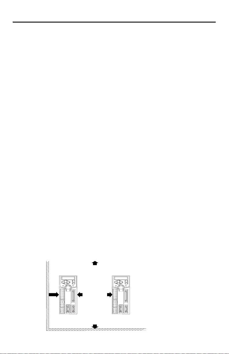
Figure 1 Clearance Requirements for 2092 Drives
50.0 mm (1.97 in.)
above drives
30.0 mm
(1.18 in.)
from adjacent
wall
Publication 2092-QS001D-EN-P — July 2005
10.0 mm
(0.39 in.)
between
drives
below drives
50.0 mm (1.97 in.)
Page 3
Ultra1500 Digital Drives Quick Start 3
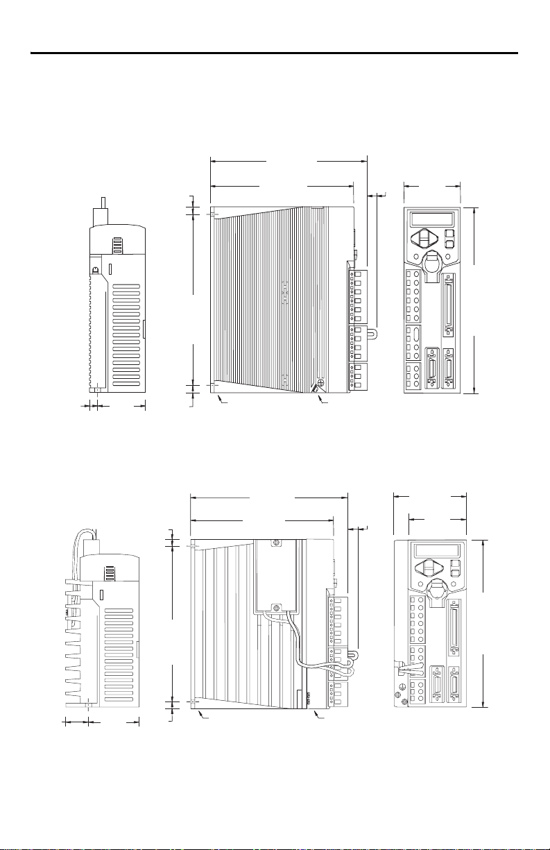
Drive Dimensions and Mounting Locations
Drive dimensions are shown in the following diagrams. Clearance requirements are shown on page 2.
Figure 2 Dimensional Outline Drawing for 2092-DA1 and 2092-DA2
153.0
5.0
(0.20)
(6.02)
140.0
(5.51)
145.0
(5.70)
12.0
(0.47)
55.0
(2.17)
155.0
(6.10)
5.0
(0.20)
Dimensions are in millimeters (inches). Drives are designed to metric dimensions; inches are mathematical conversion.
50.0
(1.97)
5.0
(0.20)
Mounting hole (top)
and slot (bottom)
require M4 x 10 bolts
Chassis ground
terminal
Figure 3 Dimensional Outline Drawing for 2092-DA3
153.0
(6.02)
5.0
(0.20)
145.0
(5.70)
20.0
(0.79)
Dimensions are in millimeters (inches). Drives are designed to metric dimensions; inches are a mathematical conversion.
50.0
(1.97)
5.0
(0.20)
Mounting hole (top) and
slot (bottom) require
M4 x 10 bolts
140.0
(5.52)
12.0
(0.47)
Chassis ground terminals (2)
70.0
(2.76)
55.0
(2.17)
155.0
(6.10)
Publication 2092-QS001D-EN-P — July 2005
Page 4
4 Ultra1500 Digital Drives Quick Start
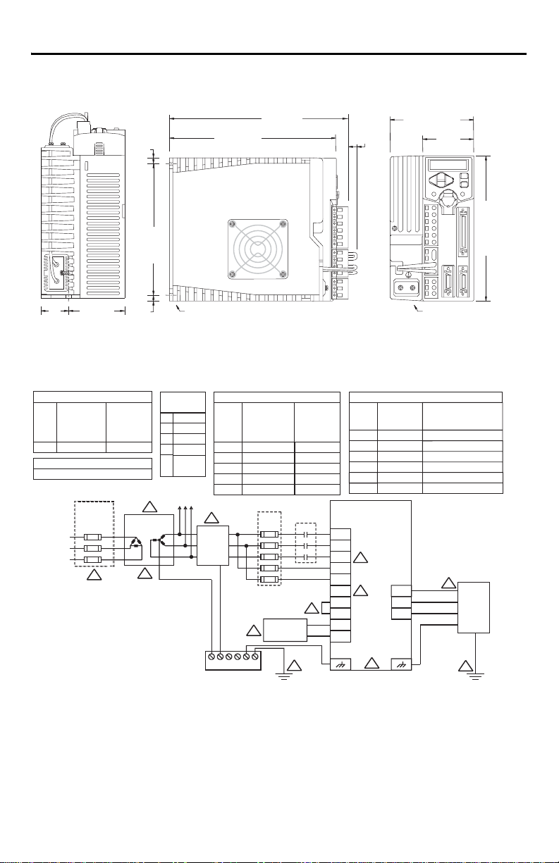
Figure 4 Dimensional Outline Drawing for 2092-DA4 and 2092-DA5
90.0
(3.54)
55.0
(2.17)
Chassis ground
terminals (2)
155.0
(6.10)
5.0
(0.20)
185.0
(7.28)
198.0
(7.80)
12.0
(0.47)
145.0
(5.70)
63.0
27.0
(1.06)
(2.48)
5.0
(0.20)
Mounting hole (top) and slot
(bottom) require M5 x 10 bolts
Dimensions are in millimeters (inches). Drives are designed to metric dimensions; inches are a mathematical conversion.
Power Wiring Diagram
MOTOR POWER WIRES U, V, W, AND GND
MOTOR
MOTOR POWER
MATING CONNECTOR
CONTACT SIZE
2.5 mm (14 AWG)
TL-SERIES
TERMINAL STRIP ACCEPTABLE WIRE RANGES
0.8 - 2.5 mm (28 - 12 AWG)
230V
3-PHASE
AC LINE
50/60 HZ
2
2
FUSED
DISCONNECT
OR CIRCUIT
BREAKER
1
MINIMUM
RECOMMENDED
POWER WIRE SIZE
O
(75 C COPPER)
2.5 mm (14 AWG)
2
2
1:1 ISOLATION
TRANSFORMER
3
MOTOR POWER
CONNECTOR
PIN
SIGNAL
A
B
W
C
D
MOTOR CASE
(GROUND)
DRIVES
U
V
4
AC
LINE
FILTER
DRIVE
2092-DA1
2092-DA2
2092-DA3
2092-DA4
2092-DA5
INPUT POWER WIRES
TERMINALS
L1, L2, L1C, L2C, GND
L1, L2, L1C, L2C, GND
L1, L2, L1C, L2C, GND
L1, L2, L3, L1C, L2C, GND
L1, L2, L3, L1C, L2C, GND
FUSE
BLOCK
SHUNT
5
RESISTOR
MINIMUM
RECOMMENDED
POWER WIRE SIZE
O
(75 C COPPER)
2
2.5 mm (14 AWG)
2
2.5 mm (14 AWG)
2
2.5 mm (14 AWG)
2
2.5 mm (14 AWG)
2
2.5 mm (14 AWG)
M1
L1C
L2C
7
DIGITAL DRIVE MODULE INPUT CURRENT REQUIREMENTS
DRIVES
TERMINALS
2092-DA1
L1, L2, GROUND
L1, L2, GROUND
2092-DA2
L1, L2, GROUND
2092-DA3
L1, L2, L3, GROUND
2092-DA4
L1, L2, L3, GROUND
2092-DA5
L1C, L2C
ALL
ULTRA1500
2092-DA1
2092-DA2
2092-DA3
L1
2092-DA4
L2
2092-DA5
L3
8
N
9
P1
P2
B1
B2
MAXIMUM
CURRENT REQUIREMENT,
(AMPS, AC RMS)
3.3 AMPS AC at 200-240 VOLTS AC
5.5 AMPS AC at 200-240 VOLTS AC
8.0 AMPS AC at 200-240 VOLTS AC
11.0 AMPS AC at 200-240 VOLTS AC
15.0 AMPS AC at 200-240 VOLTS AC
2.0 AMPS AC at 200-240 VOLTS AC
U
V
W
11
MOTOR
Notes:
1. A supply disconnecting device is required for maintenance and safety. Local regulations should be observed.
2. If using an isolation transformer, ensure the phase to neutral/ground voltage does not exceed the input ratings of the drive.
3. Isolation transformer is optional. If used, the secondary of the transformer must be grounded.
4. AC line filter and shielded motor cable are to be used for improving the drive module's electromagnetic compatiblity (EMC), and are required to meet European EMC directive.
CAUTION: AC line filters have large leakage currents and require discharge time upon power removal.
Wiring between the drive module and filter should be kept as short as possible. The common ground bus bar should be as close to the drive as possible.
5. Internal shunt resistor is present only on 2092-DA3, 2092-DA4, and 2092-DA5 drives. B1 and B2 should be left disconnected on 2092-DA1 and 2092-DA2 drives.
6. High-frequency grounding, using heavy braided wires, should connect together the electronic equipment, electrical enclosure, machine frame, and motor housing.
7. If the power factor or harmonic distortion needs improvement, the jumper from P1 to P2 can be replaced with an inductor.
8. 2092-DA1, 2092-DA2, and 2092-DA3 drives are single-phase AC input drives; input power is not connected to L3 on these drives. .
9. DC Bus Voltage connection - not an AC power input.
10. 2092-DA1 and 2092-DA2 drives have one grounding screw on the heatsink. 2092-DA3, 2092-DA4, and 2092-DA5 drives have two grounding screws on the heatsink.
Tighten the ground terminal screw(s) to 1.25 Nm (11 lbs-in.)
11. Refer to manual included with motor for power, feedback, and brake interconnect information (pinouts and/or wire colors).
12. Wire sizes are minimum recommended values. Local regulations should be observed.
GROUND BAR
6
10
6
Publication 2092-QS001D-EN-P — July 2005
Page 5
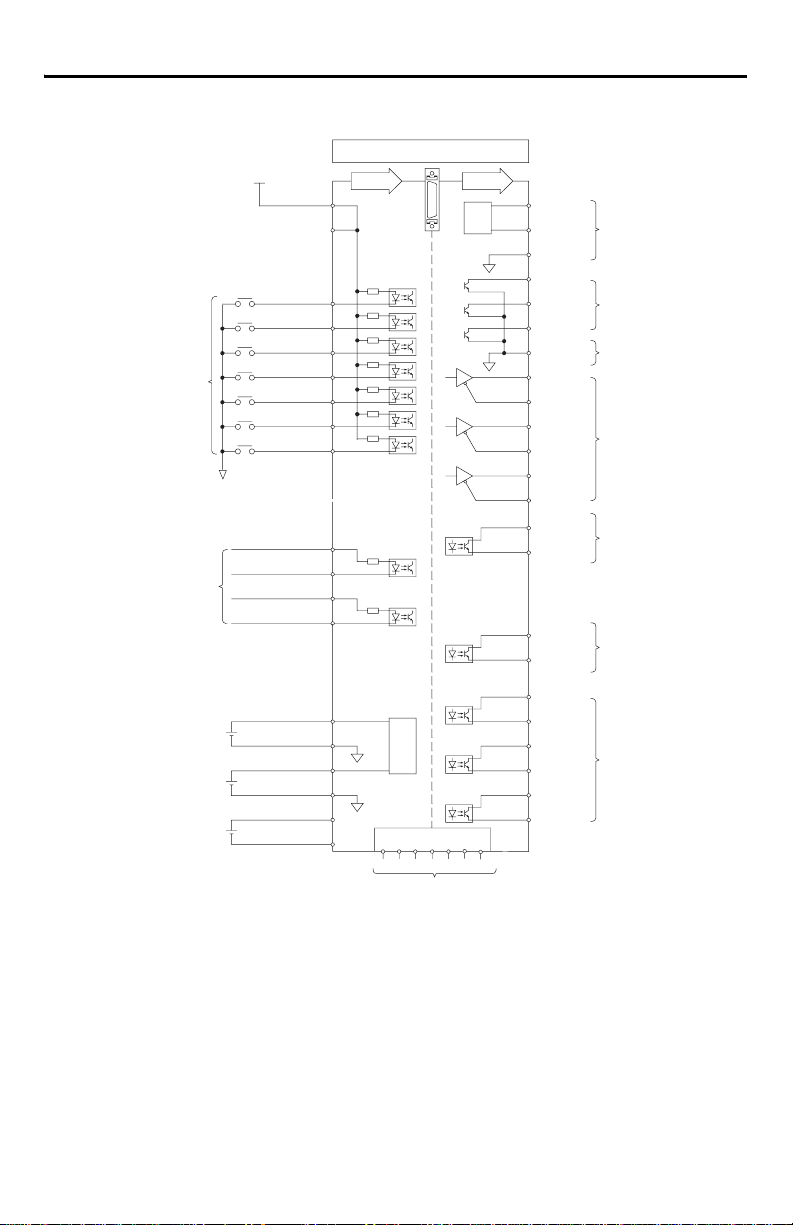
I/O Interface Diagram
24V
Active Low
Pro grammab le
Digital Inputs
24V Ground
Position
Comma nd
Speed Command
-10V to +10V
Current Command
-10V to +10V
3.6V Backup Battery
for Absolute Encoder
24V Power
+24VIN
INPUT1
INPUT2
INPUT3
INPUT4
INPUT5
INPUT6
INPUT7
AX+
AX-
BX+
BX-
VCMD+
VCMD-
ICMD+
ICMD- 22
BAT+
BAT-
CN1
Input Output
1
2
3
4
5
6
7
8
9
11
12
13
14
19
20
A/D
21
49
25
15 26 35
16 24
Ultra1500 Digital Drives Quick Start 5
28
D/A
36 50
AOUT1
23
AOUT2
27
ACOM
37
FAULT1
38
FAULT2
39
FAULT3
40
FCOM
29
AM+
30
AM-
31
BM+
32
BM-
33
IM+
34
IM-
17
Z-PULSE+
18
Z-PULSE-
45
FAULT+
46
FAULT-
41
OUTPUT1+
42
OUTPUT1-
43
OUTPUT2+
44
OUTPUT2-
47
OUTPUT3+
48
OUTPUT3-
Analog Output
-10V to +10V
Binary
Fault
Code
Output
Binary Fault
Code Ground
Buffer ed
Encoder
Output
Encoder
Marker
Pulse
Fault
Output
24V
Pro grammab le
Digital
Outputs
Reserved
Drive Setup
The Setup Wizard found in the Commands menu of Ultraware software (v1.60 or higher) is a quick
way to configure your Ultra1500 servo system. A step-by-step procedure assists in the selection of
controls and motor to be configured with the Ultra1500 drive, and then tunes the assembled system.
For detailed hardware, interconnect, and application related information about Ultra1500 drives, refer
to the following:
• The on-line help provided with Ultraware software, v1.60 or higher (catalog no. 2098-UWCPG).
• The Ultra1500 Digital Drive User Manual (publication 2092-UM001x-EN-E).
Publication 2092-QS001D-EN-P — July 2005
Page 6

6 Ultra1500 Digital Drives Quick Start
Figure 5 Ultra1500 Front Panel Display and Connections
7-Segment LED
Display
Left/Right and
Up/Down Keys
Main Power Indicator
Input Power
L1 - Main AC Power
L2 - Main AC Power
L3 - Main AC Power
L1C - Control Power
L2C - Control Power
N - DC Bus Negative
DC Bus and Shunt Power
P1 - Diode Bridge Output
P2 - DC Bus Positive
B1 - Shunt Resistor +
B2 - Shunt Resistor -
Motor Power
U - Mtr Power U-Phase
V - Mtr Power V-Phase
W - Mtr Power W-Phase
CN3 - Serial Interface
1 - GND
2 - Reserved
3 - GND
4 - Reserved
5 - GND
6 - Reserved
7 - Reserved
8 - VCC
9 - VCC
10 - VCC
11 - XMT
12 - RCV
13 - Reserved
14 - Reserved
15 - Reserved
16 - Reserved
17 - Reserved
18 - Reserved
19 - Reserved
20 - Reserved
CN2 - Motor Feedback
1 - ECOM
2 - TS
3 - A+
4 - A5 - B+
6 - B7 - I+
8 - I9 - Reserved
10 - S1/SD+
BATT
L3
L1C
P1P2B1B2 L1L2L2CN
CN3
UVW
CN1
CN2
11 - Reserved
12 - Reserved
13 - SD14 - S2
15 - Reserved
16 - S3
17 - Reserved
18 - BAT+
19 - BAT20 - EPWR
Mode/Set Key
Enter Key
Control Power Indicator
Battery Holder (connector inside)
1 - Positive 2 - Negative
CN1 - Input/Output
1 - +24V IN
2 - +24V IN
3 - INPUT1
4 - INPUT2
5 - INPUT3
6 - INPUT4
7 - INPUT5
8 - INPUT6
9 - INPUT7
10 - Reserved
11 - AX+
12 - AX13 - BX+
14 - BX15 - Reserved
16 - Reserved
17 - Z-PULSE+
18 - Z-PULSE19 - VCMD+
20 - VCMD21 - ICMD+
22 - ICMD23 - AOUT2
24 - Reserved
25 - BAT-
26 - Reserved
27 - ACOM
28 - AOUT1
29 - AM+
30 - AM31 - BM+
32 - BM33 - IM+
34 - IM35 - Reserved
36 - Reserved
37 - FAULT1
38 - FAULT2
39 - FAULT3
40 - FCOM
41 - OUTPUT1+
42 - OUTPUT143 - OUTPUT2+
44 - OUTPUT245 - FAULT+
46 - FAULT47 - OUTPUT3+
48 - OUTPUT349 - BAT+
50 - Reserved
Publication 2092-QS001D-EN-P — July 2005
Page 7

Ultra1500 Digital Drives Quick Start 7
Mating Connectors
Connector Type Wire Size A-B Connector Kit or
Input Power Single-row, spring
DC Bus and Shunt Power Wago 231-204/026-000
Output (Motor) Power Wago 231-203/026-000
CN1 - Input/Output 50-pin mini-D 0.2 mm
CN2 - Motor Feedback 20-pin mini-D 9101-1477
clamp connectors
with 7.5 mm spacing
2
2.5 - 0.8 mm
(12 - 28 AWG)
8 mm (0.3 in.) of wire
exposed
2
(24 - 30 AWG)
Manufacturer P/N
Wago 231-206/026-000
9101-1476
1
1
1
CN3 - Serial Interface 20-pin mini-D
1 Tool (Wago 231-131) for opening individual cage clamps on abo ve power connectors is supplied.
Drive Displays
The 7-segment display provides operational information when the drive is functioning, or warning/
error messages when abnormalities are encountered.
Normal operational information consists of six characters that display data in three categories. The
categories consist of a Control Mode (characters 0 and 1), a Row Display (2), and Status (3 to 5).
Figure 6 depicts these categories and defines the information provided. Overtravel displays (see the
table following Figure 6) occur if the drive detects an overtravel condition.
Figure 6 Operational Drive Displays
Character: 0 1 2 3 4 5
Control Mode: Characters 0 and 1
C = Analog Current
d = Dual Current Command
F = Follower
S = Analog Speed
P = Preset Velocity
Row Display: Character 2
Top Row = Inactive for any Current mode
Active if Velocity Mode. and Velocity Error is within the velocity window
Active if Follower Mode. and Position Error is within following error setting
Middle Row = Active if velocity exceeds Up To Speed parameter
Bottom Row = Active for hall startup motors once the commutation angle is set
Active for TL motor once the first index pulse occurs
Status: Characters 3 through 5
rdy = Drive is disabled, but ready to be enabled
run = Drive is enabled and motor is under control
Overtravel Display Possible Cause Action/Solution
A Positive Overtravel condition is
detected.
Apply motion in a negative direction to back
off limit.
Positive Overtravel
A Negative Overtravel condition is
detected.
Apply motion in a positive direction to back
off limit.
Negative Overtravel
Publication 2092-QS001D-EN-P — July 2005
Page 8

8 Ultra1500 Digital Drives Quick Start
Warning and Error Displays
Warnings or errors are displayed by the drive as shown and explained in the following tables.
• Warnings are drive abnormalities that allow motor control to continue. The Warning display
uses only the last three digits of the six-digit display.
• Errors are serious abnormalities that do not allow motor control. The Error display alternates
between a three-digit error code and a six-digit text message.
Warning Display Possible Cause Action/Solution
3.2V or less output from encoder battery
Absolute Encoder Battery
or external power supply.
Control power is applied to the drive
Power Up Overspeed
while the motor is in motion.
Improper setting of analog current scale Verify scaling parameter corresponds to
Over Current Command
System cannot meet motion profile • Verify velocity loop tuning.
Incorrect current limit settings Verify current limits do not restrict current to
Improper setting of analog velocity scale Verify scaling parameter corresponds to
Over Speed Command
System cannot meet motion profile • Verify position loop tuning.
Inappropriate assignment of digital
Digital I/O Assignment
1 Battery replacement causes los s of absolute position. Homing m ay be necessary.
Error
Code
Tex t
Message
inputs or outputs
Possible Cause Action/Solution
Motor thermal switch trips due to:
Motor Overtemperature
• High motor ambient temperature,
and/or
• Excessive current
Motor wiring error Check motor wiring.
Incorrect motor selection Verify the proper motor has been selected.
Replace battery or verify external power
1
supply.
After verifying motor has stopped, recycle
control power.
analog signal range.
• Verify system sizing.
less than system capabilities.
analog signal range.
• Verify system sizing.
• If operated in preset mode, verify presets
are assigned.
• If operated in a normal/override mode,
verify the override function is assigned.
• Operate within (not above) the continuous
torque rating for the ambient temperature.
• Lower ambient temperature, or increase
motor cooling.
Publication 2092-QS001D-EN-P — July 2005
Page 9

Ultra1500 Digital Drives Quick Start 9
Error
Code
Tex t
Message
IPM Error
Bus Undervoltage
Bus Overvoltage
Motor Overspeed
Excess Position Error
Motor Continuous Current
Overload
Possible Cause Action/Solution
Motor cables shorted Verify continuity of motor power cable and
connector.
Motor winding shorted internally Disconnect motor power cables from the
motor. If the motor is difficult to turn by hand,
it may need to be replaced.
Drive temperature too high • Check for clogged vents or defective fan.
• Ensure cooling is not restricted by
insufficient space around the drive.
Operation above continuous power
rating
• Verify ambient temperature is not too
high.
• Operate within the continuous power
rating.
• Reduce acceleration rates.
Drive has a bad IPM output, short circuit,
or overcurrent
Remove all power and motors connections,
then perform a continuity check from the DC
bus to the U, V, and W motor terminals. If
continuity exists, check for wire fibers
between terminals, or send drive in for repair.
Low AC line/AC power input • Verify voltage level of the incoming AC
power.
• Check AC power sources for glitches or
line drop.
• Install uninterruptible power supply (UPS)
on the AC input.
Attempted to enable drive without main
Apply main power before enabling drive.
power active.
Excessive regeneration of power (i.e.,
When the motor is driven by an external
mechanical force, it may regenerate too
much peak energy through the drive’s
power supply and the drive faults to save
itself from an overload.)
• Verify shunt circuit.
• Adjust motion profile to stay within the
range of the regenerative resistor.
• Replace regenerative transistor.
• Replace drive.
Excessive AC input voltage Verify input is within specification.
Motor speed exceeds maximum • Confirm encoder wiring.
• Retune drive system.
• Verify input gain of external speed or
torque command.
Position error exceeds permitted value • Increase following error limit.
• Check position loop tuning.
The internal filter protecting the motor
from overheating has tripped
• Reduce acceleration rates.
• Reduce duty cycle (ON/OFF) of
commanded motion.
• Increase time permitted for motion.
• Use larger drive and motor.
• Checking tuning.
Publication 2092-QS001D-EN-P — July 2005
Page 10

10 Ultra1500 Digital Drives Quick Start
Error
Code
Tex t
Message
Drive Overload
Encoder Data Range Error
Encoder Cable Open
Encoder Data Parameter
Error
Drive Overtemperature
AC Line Loss
User Parameter
Initialization Error
Current Feedback Offset
User Parameter Checksum
Error
Watchdog Timeout
PWM Hardware Error
Possible Cause Action/Solution
The motion application requires average
drive current in excess of rated capability
• Reduce acceleration rates.
• Reduce duty cycle (ON/OFF) of
commanded motion.
• Increase time permitted for motion.
• Use larger drive and motor.
• Check tuning.
Encoder not programmed correctly Replace motor.
Encoder memory corrupted
Communication not established with an
intelligent encoder.
Hall error
• Verify motor selection.
• Verify the motor supports automatic
identification.
• Verify encoder wiring.
Encoder not programmed correctly Replace motor.
Encoder memory corrupted
Excessive heat exists in the drive • Verify cooling fan operation (2092-DA4
and 2092-DA5 only).
• Check tuning.
• Reduce acceleration rate.
• Reduce duty cycle (ON/OFF) of
commanded motion.
• Increase time permitted for motion.
• Use larger drive and motor.
Poor quality power Increase Ride Through time.
Attempted to enable drive without main
Apply main power before enabling drive.
power active
Phase connection missing Remove power and verify all physical
connections.
Fault Delay parameter is set too short Increase the Fault Delay parameter setting.
Error in parameter memory storage • Reinitialize parameter.
• Reset drive to factory defaults.
Defective hardware Replace drive.
Checksum error • Confirm and reset parameter.
• Reset drive to factory defaults.
Excessive system noise Verify wiring and installation methods.
Defective hardware Replace drive.
Defective hardware Contact A-B.
Publication 2092-QS001D-EN-P — July 2005
Page 11

Ultra1500 Digital Drives Quick Start 11
Error
Code
Tex t
Message
User Parameter Range
Error
Drive Initialization Error
Shunt Overload Protection
Shunt Overcurrent
Protection
Absolute Encoder Battery
Error
Absolute Encoder
Overspeed
Absolute Encoder
Multi-turn Count Error
Encoder Single-Turn Count
Error
Drive Set Up
Motor Power Cable Open
Motor Instantaneous
Current Overload
Motor Mismatch
Possible Cause Action/Solution
Range of parameter is invalid • Enter parameter with value(s) within
range.
• Reset drive to factory defaults.
Hardware error Replace drive.
Power at regenerative resistor exceeds
the permitted value
Shunt resistor is disconnected or
damaged
Shunt current exceeded allowable
instantaneous value
Adjust motion profile to stay within the range
of the regenerative resistor.
• Verify resistor connection.
• Verify resistance of shunt resistor.
• Verify shunt is not shorted or damaged.
• Verify load energy is not excessive during
deceleration.
Encoder Backup Battery parameter is set
to installed, but a battery is not installed.
Battery voltage is sensed below 2.7V dc. • Confirm battery voltage and connection.
Battery powered encoder is
mechanically rotated at high speed
while drive is powered down
Set Encoder Backup Battery parameter to Not
Installed.
• Replace battery.
• Mechanically disengage motor from
system.
• Cycle power to drive and reset alarm.
Noise in the encoder Cycle power to drive and reset alarm.
Defective encoder Replace motor.
Noise in the encoder Cycle power to drive and reset alarm.
Defective encoder Replace motor.
The drive operating mode and motor
selection are incompatible.
Change the operating mode and/or the motor
selection, and reset the drive.
Motor cable open Verify power connection between motor and
drive.
Motion profile requires a peak current
for an excessive time interval
• Verify motor wiring.
• Adjust accel/decel time.
• Confirm motor selection.
Defective current feedback sensing Verify phase currents.
Dynamic braking current of the selected
motor exceeds twice the drive peak
current rating
Install a different motor.
Publication 2092-QS001D-EN-P — July 2005
Page 12

12 Ultra1500 Digital Drives Quick Start
Error
Code
Tex t
Message
Continuous Power
Overload
Encoder Type Mismatch
Encoder Communication
Error
Special Communication
Error
Position Command
Frequency Error
Possible Cause Action/Solution
Motion application requires average
drive power in excess of rated capability
• Reduce acceleration rates.
• Reduce duty cycle (ON/OFF) of
commanded motion.
• Increase time permitted for motion.
• Use larger drive and motor.
• Check tuning.
Motor encoder signals do not match
drive configuration
Verify motor selection.
Defective encoder Replace motor.
Wiring between drive and encoder is
faulty or disconnected, or EMI (noise)
• Verify encoder wiring.
• Contact A-B.
disrupts encoder signals.
Communications error between host and
drive (noise)
Input frequency limit exceeded • Verify hardware type selected in the drive
• Verify serial cable.
• Check for noise on serial interface.
matches the physical hardware.
• Change from open collector to line drive.
• Reduce the speed command.
• Apply gearing.
Publication 2092-QS001D-EN-P — July 2005
Page 13

Ultra1500 Digital Drives Quick Start 13
Drive Specifications
Drive 2092-DA1 2092-DA2 2092-DA3 2092-DA4 2092-DA5
Weight 0.9 kg (1.98 lbs)
Temperature 0° C to 50° C (32° F to 122° F)
Operating Shock,
and Vibration
Short Circuit Current Rating with
No Fuse Restrictions
Short Circuit Current Rating with
Fuse Restrictions
15 G, Half Sine, 11 ms
5 – 500 Hz @ 2.5 G, 0.381 mm (0.015 in.) maximum displacement
Suitable for use on a circuit capable of delivering not more than 5000 rms
symmetrical amperes, 240 Volts maximum.
Suitable for use on a circuit capable of delivering not more than 200,000 rms
symmetrical amperes, 240 Volts maximum, when protected by high interrupt
capacity, current limiting fuses UL198C (Class CC, G, J, L, R, T).
Motor Overload Protection Utilizes solid state motor overload protection which operates:
• within 8 minutes at 200% overload.
• within 20 seconds at 600% overload
Symbols Used on Drive Protective ground conductor terminal
Certification and Compliance
1
UL® listed to U.S. and Canadian safety standards (UL 508C File E145959)
CE and C-Tick marked for all applicable directives
Main Input Power
Nominal Input Voltage (V
Input Current (A
) 3.3A 5.5A 8.0A 11.0A 15.0A
rms
2,3
200-240V, 1 phase, 50 or 60 Hz 200- 240V, 3 phase, 50 or 60 Hz
rms)
Maximum Inrush Current (0-peak) 200A
Maximum Power Cycles/Minute 1 power cycle/2 minute interval
DC Bus Discharge Time 3 minutes after removal of main AC power
Control Input Power
Input Voltage (V
Input Current (A
2,3
)
200-240V, 1 phase, 50/60 Hz
rms
)2.0A
rms
Maximum Inrush Current (0-peak) 75A
Motor Output
Continuous Output Current (0-peak)
Intermittent Output Current (0-peak)
Continuous Output Power @ 240Vac
1.4A 2.4A 4.7A 10.7A 16.4A
3.4A 7.2A 11.3A 24.8A 43.4A
400W 650W 1000W 3000W 4000W
Power Dissipation
Maximum Power Dissipation
1 Refer to www.ab.com/certification/ce/doc for more information.
2 Nominal values are listed. Abso lute range is 180 to 264 V
3 The AC input voltage between any two in put power pins (L1, L2, L3, L1C, L2C, and CHASSIS) must not exceed this r ating. This note also applies to the
CHASSIS ground connection, which im plies that transformer secondaries must be grounded.
4 Maximum Power Dissipation in cludes dissipative power of drive plus the Continuous Shunt Power rating of the drive’s internal shunt.
50W 50W 50W +30W
.
rms
1.2 kg (2.65 lbs)
2.1 kg (4.63 lbs)
4
100W+50W 4 150W+70W 4
Publication 2092-QS001D-EN-P — July 2005
Page 14

14 Ultra1500 Digital Drives Quick Start
Drive 2092-DA1 2092-DA2 2092-DA3 2092-DA4 2092-DA5
Internal Shunt Power
Continuous Shunt Power
Instantaneous Shunt Power
– – 30W 50W 70W
– – 3000W 3000W 5000W
Digital Input/Output Specifications
Type Active Low, current sinking
External Power Supply
Requirements
Voltage: 21.6V to 26.4V
Maximum Current Draw: 64 mA
Note: Digital I/O is not powered by an internal supply, customer must connect an
external power supply.
Analog Input/Output Specifications
Inputs Voltage range is -10V to +10V
Impedance of10 k Ω.
A/D conversion with 16-bit resolution
Outputs Voltage range -10V to +10V
Current output of up to 10 mA into a resistive load
D/A conversion with 12-bit resolution
Motor Control Specifications
Feedback Device Power 5V supplied by drive for incremental and serial encoder devices.
Incremental Encoder
Requirements
Differential drivers for A, B, Z, and single-ended Hall signals S1, S2, and S3
Maximum line frequency: 4,000,000 lines/second (16,000,000 counts second)
Fuse and Contactor Recommendations
Main Power Fuses
Recommended Fuse Group 1
Recommended Fuse Group 2 3
Control Power Fuses 1
Recommended Fuse Group 1 4 FRS-R-2-1/2
Recommended Fuse Group 2
Recommended Fuse Group 3
Contactor
1 Fuses specified are Bussmann® fuses.
2 FNQ-R fuses are described as Time-Delay Fus es, Class CC.
3 LPJ fuses are described as Dual-Elem ent Time-Delay Fuses, Class J.
4 FRS-R fuses are described as Dual-E lement Time-Delay Fuses, Class RK5.
5 For contactors: x represents coil voltage, and y represents number of contacts.
Publication 2092-QS001D-EN-P — July 2005
1
2092-DA1 2092-DA2 2092-DA3 2092-DA4 2092-DA5
2
FNQ-R-7 FNQ -R-10 FNQ-R-15 FNQ-R-20
NA LPJ-15 LPJ-20
2
FNQ-R-7-1/2
3
LPJ-6
5
100-M05Nxy 100-M09Nxy 100-M12Nxy 100-C16xy 100-C23xy
Page 15

Ultra1500 Digital Drives Quick Start 15
Accessories
Catalog Number or Item Description and/or Specifications
2090-DA-BAT 3.6V Battery with connector (for multi-turn encoder)
AC Line Filters 2092-DA1 2092-DA2 2092-DA3 2092-DA4 2092-DA5
2090-UXLF-106
Connector Kits
9101-1476 50 pin Mini-D Connector Kit (solder cup type) for CN1
9101-1477 20 pin Mini-D Connector Kit (solder cup type) for CN2 and CN3
Cables
2090-DANFCT-Sxx
2090-DANBT-18Sxx
2090-DANPT-16Sxx
2090-DAIO-D50xx
2090-DAPC-D09xx
1 Cable length (xx) is specified in meters: xx = 01, 03, 09, etc. Consult Motion Control Selection Guide (GMC-SG001x-EN-P) for available lengths.
1
Feedback Cable for TL-Series Motors, connectors both ends
1
Brake Cable for TL-Series Motors, ring lugs to drive
1
Power Cable for TL-Series Motors, ferruled leads to drive
1
CN1 Control Cable, connector to drive, flying leads to controller
1
PC Cable, connectors both ends
2090-UXLF-110
2090-UXLF-HV323
Publication 2092-QS001D-EN-P — July 2005
Page 16

Related Documentation
These publications provide additional information; specifically about Rockwell Automation drives. To
obtain a copy, contact your local Rockwell Automation office or distributor, or access the documents
on-line at www.rockwellautomation.com/literature.
For information about: Read this document: Publication Number
Ultra1500 drive configuration and operation Ultra1500 Digital Drive User Manual 2092-UM001x-EN-E
Programming motion using Ultra1500 drives Help files for v1.6 or higher of
Ultraware
A glossary of industrial automation terms and
abbreviations
How to minimize and control system-level noise. System Design for Control of
An overview of Allen-Bradley motion controls
Allen-Bradley Industrial Automation
Glossary
Electrical Noise Reference Manual
Motion Control Selection Guide GMC-SG001x-EN-P
and systems, including this and other products
General guidelines for personal safety in the
application, installation, and maintenance of
solid state controls
An article on wire sizes and types for grounding
Safety Guidelines for the Application,
Installation and Maintenance of
Solid-State Control
National Electrical Code Published by the
electrical equipment
Ultraware CD
(Ctlg. No. 2098-UWCPG)
AG-7.1
GMC-RM001x-EN-P
SGI-IN001A-EN-P
National Fire Protection
Association of Boston,
MA
For more information refer to our web site:
For Rockwell Automation Technical Support information refer to:
Allen-Bradley is a registered trademarks of Rockwell Automation, Inc.
Bussman is a registered trademark of Cooper Industries, Inc.
UL is a registered trademark of Underwriters Laboratories, Inc.
Ultra1500 and Ultraware are trademarks of Rockwell Automation, Inc.
www.ab.com/motion
www.ab.com/support
or Tel: (1) 440.646.5800
Publication 2092-QS001D-EN-P — July 2005 PN 0013-2066-004
Supersedes publication 2092-QA001C-EN-P — July 2004 Copyright © 2005 Rockwell Automation, Inc. All rights reserved. Printed in the USA.
 Loading...