

Page 1
Installation Instructions
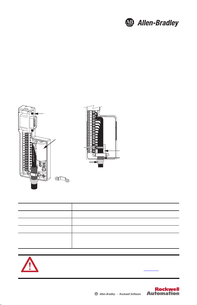
If necessary, turn clamp over to hold small wires secure.
Mounting
Screw (2)
Tie wrap secures
wire bundles.
Shrink-wrapped
Insulation
Follow these steps to form a compact
connection.
1. Push the insulation down-and-over itself.
2. Move the insulation so it butts against the
outside wall of the cover.
3. Tape or shrink-wrap the end of the
insulation to the cable.
Battery (optional)
Cable Shield Termination Pad
Cable Shi eld
Low-profile Connector Kit for
Motor Feedback Signals
Catalog Numbers 2090-K2CK-D15M, 2090-DA-BAT2
Install the Low-profile Connector Kit
2090-K2CK-D15M Connector Kit Specifications
Attribute Value
Cable diameter 4…10 mm (0.16…0.39 in.)
2
Screw te rminal wire si ze 0.06…1 .31 mm
Recommended wire strip length 5 mm (0.2 in.) single conductor
Recommended torque
Mounting screw
Ter mi nal scr ew
ATTENTION: This connector kit contains electrostatic discharge (ESD) sensitive parts that can be
damaged if you do not follow ESD control procedures. If you are unfamiliar with ESD control
procedures, refer to Guarding Against Electrostatic Damage, publication 8000-4.5.2
applicable ESD protection handbook.
0.40 N•m (3.5 lb•in)
0.25 N•m (2.2 lb•in)
(30…16 AWG)
, or any other
Page 2
2 Low-profile Connector Kit for Motor Feedback Signals
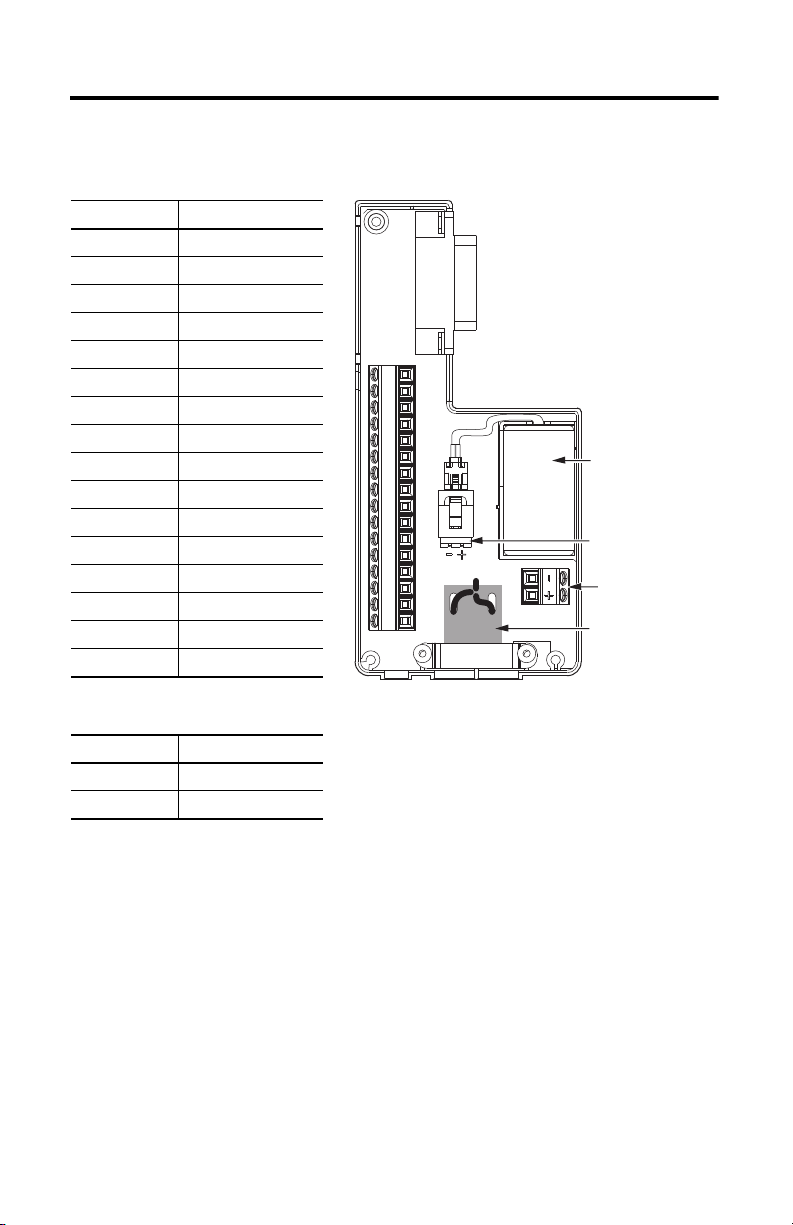
Optional Battery (BAT)
BAT Connections
BAT Terminals
Cable Shi eld
Termination Pad
Connector Data
Motor Feedback (MF) Connections
Terminal Signal
1AM+
2AM–
3BM+
4BM–
5DATA+/IM+
6ECOMM
7EPWR_9V
8S3
9E_OT+
10 DATA–/IM–
11 TS
12 S1
13 S2
14 EPWR_5V
15 E_OT–
0 SHIELD
14 13 12 11 10 9 708654312
15
Optional Battery Connections
Terminal Signal
+BAT+
–BAT–
Rockwell Automation Publication 2093-IN005C-EN-P - May 2013
Page 3
Low-profile Connector Kit for Motor Feedback Signals 3
Battery Specifications
The 2090-DA-BAT2 battery is required for absolute position backup of TL-Series encoders, but
is not included with the connector kit.
Battery Catalog Number
Cat. No. Description
2090-DA-BAT2 3.6V, half-height, non-rechargeable lithium battery with 2-pole mini connector
Battery Life
Drive Power On Time
Hours/week
0 168 1.0 Drive power is never ON
40 128 3.5 Drive power is ON for one 8-hour shift,
56 112 4.0 Drive power is ON for one 8-hour shift,
80 88 5.5 Drive power is ON for two 8-hour shifts,
112 56 7.5 Drive power is ON for two 8-hour shifts,
120 48 8.0 Drive power is ON for three 8-hour shifts,
168 0 10.5 Drive power is never OFF
Drive Power Off Time
Hours/week
This product contains a sealed lithium battery which may need to be replaced during the life of the product.
At the end of its life, the battery contained in this product should be collected separately from any unsorted
municipal waste.
The collection and recycling of batteries helps protect the environment and contributes to the conservation of
natural resources as valuable materials are recovered.
Expected Battery Life
Yea r s
Operating Conditions
5 days/week
7 days/week
5 days/week
7 days/week
5 days/week
Rockwell Automation Publication 2093-IN005C-EN-P - May 2013
Page 4
Rockwell Automation Support
Rockwell Automation provides tec hnical information on the Web to assist you in using its products.
At http://www.rockwellautomation.com/support
links to software service packs, and a MySupport feature that you can customize to make the best use of these tools. You can also visit
our Knowledgebase at http://www.rockwellautomation.com/knowledgebase
forums, software updates, and to sign up for product notification updates.
For an additional level of technical phone support for installation, configuration and troubleshooting, we offer TechConnect
support programs. For more information, contact your local distributor or Rockwell Automation representative, or visit
http://www.rockwellautomation.com/support/
Installation Assistance
If you experience a problem within the first 24 hours of installation, please review the information that's contained in this manual.
You can also contact a special Customer Support number for initial help in getting your product up and running.
United States or Canada 1.440.646.3434
Outside United States or
Canada
Use the Wor ldwi de Loc ator
http://www.rockwellautomation.com/rockwe llautomation/support/overview.page
local Rockwell Automation representative.
New Product Satisfaction Return
Rockwell Automation tests all of its products to help ensure that they are fully operational when shipped from the manufacturing
facility. However, if your product is not functioning and needs to be returned, follow these procedures.
, you can find technical manuals, technical and application notes, sample code and
for FAQs, technical information, support chat and
SM
.
at
, or contact your
United States
Outside United States Please contact your local Rockwell Automation representative for the return procedure.
Contact your distributor. You must provide a Customer Support case number (call the phone number
above to obtain one) to your distributor to complete the return process.
Documentation Feedback
Your comments will help us serve your documentation needs better. If you have any suggestions on how to improve this document,
complete this form, publication RA-DU002
Allen-Bradley, Rockwell Software, Rockwell Automation, and TechConnect are trademarks of Rockwell Automation, Inc.
Trademarks not belong ing to Rockwell Automation are property of their respective companies.
Rockwell Otomasyon Ticaret A.Ş., Kar Plaza İş Merkezi E Blok Kat:6 34752 İçerenköy, İstanbul, Tel: +90 (216) 5698400
Publication 2093-IN005C-EN-P - May 2013 PN-204918
Supersedes Publication 2093-IN005B-EN-P - August 2010 Copyright © 2013 Rockwell Automation, Inc. All rights reserved. Printed in the U.S.A.
, available at http://www.rockwellautomation.com/literature/.
 Loading...