

Page 1
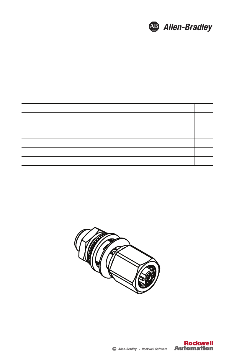
Installation Instructions
Kinetix 6000M Bulkhead Adapter Kit for
Network Cables
Catalog Number 2090-CBUSPSS
Topi c Page
Important User Information 2
Before You Begin 3
Install the Adapter Kit 4
2090-CBUSPSS Mounting Dimensions and Pinouts 5
Specifications 6
Additional Resources 7
About the Adapter Kit
The Kinetix® 6000M bulkhead adapter kit for network cables is a cost-effective and reliable
adapter that passes network signals for an integrated drive-motor (IDM) system through a
cabinet wall or other physical barriers.
Page 2
2 Kinetix 6000M Bulkhead Adapter Kit for Network Cables
Important User Information
Solid state equipment has operational characteristics differing from those of electromechanical equipment. Safety Guidelines for
the Application, Installation and Maintenance of Solid State Controls, publication SGI-1.1
Automation sales office or online at http://www.rockwellautomation.com/literature
between solid state equipment and hard-wired electromechanical devices. Because of this difference, and also because of the
wide variety of uses for solid state equipment, all persons responsible for applying this equipment must satisfy themselves that
each intended application of this equipment is acceptable.
In no event will Rockwell Automation, Inc. be responsible or li able for indirect or consequential damages resulting from the use or
application of this equipment.
The examples and diagrams in this manual are included solely for illustrative purposes. Because of the many variables and
requirements associated with any particular installation, Rockwell Automation, Inc. cannot assume responsibilit y or liability for
actual use based on the examples and diagrams.
No patent liability is assumed by Rockwell Automation, Inc. with respect to use of information, circuits, equipment, or software
described in this manual.
Reproduction of the contents of this manual, in whole or in part, without written permission of Rockwell Automation, Inc., is
prohibited.
Throughout this manual, when necessary, we use notes to make you aware of safety considerations.
WARNIN G: Identifies information about practices or circumstances that can cause an explosion in a
hazardous environment, which may lead to personal injury or death, property damage, or economic
loss.
, is available from your local Rockwell
) describes some important differences
ATTENTION: Identifies information about practices or circumstances that can lead to personal injury or
death, property damage, or economic loss. Attentions help you identify a hazard, avoid a hazard and
recognize the consequences.
SHOCK HAZARD: Labels may be on or inside the equipment, for example, drive or motor, to alert
people that dangerous voltage may be present.
BURN HAZARD: Labels may be on or inside the equipment, for example, drive or motor, to alert
people that surfaces may reach dangerous temperatures.
IMPORTANT Identifies information that is critical for successful application and understanding of the product.
Publication 2090-IN039B-EN-P - March 2012
Page 3
Kinetix 6000M Bulkhead Adapter Kit for Network Cables 3
Before You Begin
Remove all packing material from within and around the item. After unpacking, verify the
catalog number against the purchase order, and visually inspect the cable and each connector for
damage. If necessary, immediately notify the carrier of any shipping damage.
Observe the following precautions when installing the cables in a servo system. Failure to observe
these safety notices could result in personal injury or damage to the motor and equipment.
SHOCK HAZARD: To avoid the hazard of electrical shock, be sure to ground any cable providing
power at a minimum of one point. To prevent the build-up of electrical energy, factory-supplied
cables use one of these grounding techniques:
• Bond the overall shield to the connector housing.
• Make sure there is a dire ct connect ion-to-ground for each cable shield.
• Connect an exposed cable braid or a ground wire, if present, to the power cable clamp,
housing, or another suitable chassis ground.
Failure to observe these safety procedures could result in personal injury or equipment damage.
ATT EN TI ON : Arcing or unexpected motion can occur if cables are connected or disconnected while
power is applied to the IDM sy stem. Before working on an IDM system, disconnect power and wait
the full time interval as indicated in the warning on the IPIM module or verify the DC bus voltage at
the IPIM module measures less than 50V DC.
Failure to observe this precaution could result in severe bodily injury or loss of life, and damage to
the product will occur.
ATT EN TI ON : The maximum length of cabling between the IPIM and the last IDM unit in the
system must not exceed 100 m (328 ft). Also, a maximum of two extension cables may be
connected between an IDM unit and the preceding IPIM module or IDM unit.
Publication 2090-IN039B-EN-P - March 2012
Page 4

4 Kinetix 6000M Bulkhead Adapter Kit for Network Cables
Limited
Bend Zone
Installation Area
150 mm ± 25 (6 ± 1.0)
2090-CNSSPRS cable shown
M12 Female PlugM12 Male Plug
Installation Area
150 mm ± 25 (6 ± 1.0)
Dimensions are in mm and (in.).
Install the Adapter Kit
Follow these steps when installing an adapter kit.
1. Verify that space is provided for the cables that must connect through the adapter.
• The installation area must provide clearance for cable features that are greater than or
equal to the cable diameter.
Examples of cable features include: connectors, transitions from exposed wire to
insulation (for example, flying leads), exposed cable ground shields.
• Provide sufficient area around the adapter so the M12 connectors. that require
multiple rotations, can be hand-tightened.
• Network cables have a static or one-time bend radius of twelve times the cable
diameter.
2. Create a panel cutout 15.9 mm (0.62 in.) in diameter.
3. Install the bulkhead adapter kit in the panel cutout, with one isolator on each side of the
panel as shown in the diagram on page
4. Observe these restrictions when installing the connecting cables:
5.
• Prevent the cable from flexing within 150 ±25 mm (6 ±1 in.) installation areas.
• Bend cables to a specific shape only in the bend zone area.
• Provide cable supports at 3 m (10 ft) intervals along the cable run to reduce tension
and flexing at the connectors and other features on the cable.
Publication 2090-IN039B-EN-P - March 2012
Page 5

Kinetix 6000M Bulkhead Adapter Kit for Network Cables 5
25.4 mm (1.0 in.)
Max. Wall Thickness
19.6
(0.77)
17.5
(0.69)
19.4
(0.76)
Gasket
M12 x 1
29.4
(1.16)
47.7
(1.88)
M12 Female
Connector
IsolatorIsolator
Locknut L N-M12
Lockwasher LW-M12
17.0
(0.67)
M12 Male Connector M12 Female Connector
M12 Male
Connector
Dimensions are in mm (in.).
2090-CBUSPSS Mounting Dimensions and Pinouts
Publication 2090-IN039B-EN-P - March 2012
Page 6

6 Kinetix 6000M Bulkhead Adapter Kit for Network Cables
Specifications
2090-CBUSPSS Bulkhead Adapter Kit for Network Cables
Attribute Value
Contact carrier Nylon or Thermoplastic Polyurethane
Contact material/plating Brass/Gold
Housing material/plating Brass/Nickel
Rated current 4.0 A
Temperature range -40…105° C (40…221° F)
Protection class NEMA 1, 3, 4, 6P
Insulation resistance >
Gasket material Nitrile
Isolator material Nylon
IEC IP67
109 Ω
Publication 2090-IN039B-EN-P - March 2012
Page 7

Kinetix 6000M Bulkhead Adapter Kit for Network Cables 7
Additional Resources
These documents contain additional information concerning related products from Rockwell
Automation.
Resource Description
Integrated Drive-Moto r User Manual, publication 2094-UM003
Kinetix 6000M Integrated Drive Motor (IDM) Installation
Instructions, publication MDF-IN001
Allen-Bradley Industrial Automation Glossary, publication
AG-7.1
System Design for Control of Electrical Noise Reference Manual,
publication GMC-RM001
Kinetix Rotary Motion Specifications Technical Data,
publication GMC-TD001
Kinetix Motion Accessories Technical Data,
publication GMC-TD004
Kinetix Motion Control Selection Guide,
publication GMC-SG001
Information on installing, configuring, starting, and
troubleshooting a servo drive system with a servo motor.
Information on the installation of your Kinetix 6000M
integrated drive-motor.
A glossary of industrial automation terms and abbreviations.
Information, examples, and techniques designed to minimize
system failures caused by electrical noise.
Catalog numbers and product specifications, including
performance, environmental, certifications, load force, and
dimension drawings for Allen-Bradley rotary motors.
Catalog numbers, specifications, and dimensions for
Allen-Bradley servo drive accessories.
General product specifications for Kinetix motion control
products.
You can view or download publications at http://www.rockwellautomation.com/literature
.
To order paper copies of technical documentation, contact your Allen-Bradley® distributor or
Rockwell Automation® sales representative.
Publication 2090-IN039B-EN-P - March 2012
Page 8

Rockwell Automation Support
Rockwell Automation provides tec hnical information on the Web to assist you in using its products.
At http://www.rockwellautomation.com/support
links to software service packs, and a MySupport feature that you can customize to make the best use of these tools. You can also visit
our Knowledgebase at http://www.rockwellautomation.com/knowledgebase
forums, software updates, and to sign up for product notification updates.
, you can find technical manuals, technical and application notes, sample code and
for FAQs, technical information, support chat and
For an additional level of technical phone support for installation, configuration and troubleshooting, we offer TechConnect
programs. For more information, contact your local distributor or Rockwell Automation representative, or visit
http://www.rockwellautomation.com/support/
.
® support
Installation Assistance
If you experience a problem within the first 24 hours of installation, please review the information that's contained in this manual.
You can also contact a special Customer Support number for initial help in getting your product up and running.
United States or Canada 1.440.646.3434
Outside United States or
Canada
Use the Wor ldwi de Loc ator
http://www.rockwellautomation.com/support/americas/phone_en.html
Rockwell Automation representative.
at
, or contact your local
New Product Satisfaction Return
Rockwell Automation tests all o f its products to ensure that they are fully operational when shipped from the manufacturing facility.
However, if your product is not functioning and needs to be returned, follow these procedures.
United States
Outside United States Please contact your local Rockwell Automation representative for the return procedure.
Contact your distributor. You must provide a Customer Support case number (call the phone number
above to obtain one) to your distributor to complete the return process.
Documentation Feedback
Your comments will help us serve your documentation needs better. If you have any suggestions on how to improve this document,
complete this form, publication RA-DU002
, available at http://www.rockwellautomation.com/literature/.
Allen-Bradley, Kinetix, Rockwell Automation, and TechConnect are trademarks of Rockwell Automation, Inc.
Trademarks not belonging to R ockwell Automation are property of their respective companies.
Publication 2090-IN039B-EN-P - March 2012 PN-143966
Supersedes Publication 2090-IN039A-EN-P - February 2012 Copyright © 2012 Rockwell Automation, Inc. All rights reserved. Printed in the U.S.A.
 Loading...