

Page 1
Ultra3000
Digital Servo Drives
(Catalog Numbers
2098-DSD-005, -010, and -020
2098-DSD-xxxX
2098-DSD-xxx-SE
2098-DSD-xxx-DN
2098-DSD-xxxX-DN
2098-DSD-030, -075, and -150
2098-DSD-xxxX
2098-DSD-xxx-SE
2098-DSD-xxx-DN
2098-DSD-xxxX-DN
2098-DSD-HV030, -HV050, -HV100, -HV150,
and -HV220
2098-DSD-HVxxxX
2098-DSD-HVxxx-SE
2098-DSD-HVxxx-DN
2098-DSD-HVxxxX-DN)
Installation Manual
Page 2
Important User Information
Because of the variety of uses for the products described in this
publication, those responsible for the application and use of this
control equipment must satisfy themselves that all necessary steps
have been taken to assure that each application and use meets all
performance and safety requirements, including any applicable laws,
regulations, codes and standards.
The illustrations, charts, sample programs and layout examples
shown in this guide are intended solely for purposes of example.
Since there are many variables and requirements associated with any
particular installation, Allen-Bradley
or liability (to include intellectual property liability) for actual use
based upon the examples shown in this publication.
Allen-Bradley publication SGI-1.1, Safety Guidelines for the
Application, Installation and Maintenance of Solid-State Control
(available from your local Allen-Bradley office), describes some
important differences between solid-state equipment and
electromechanical devices that should be taken into consideration
when applying products such as those described in this publication.
®
does not assume responsibility
Reproduction of the contents of this copyrighted publication, in
whole or part, without written permission of Rockwell Automation
is prohibited.
Throughout this manual we use notes to make you aware of safety
considerations:
ATTENTION
Identifies information about practices or
circumstances that can lead to personal injury or
death, property damage or economic loss.
®
!
Attention statements help you to:
• identify a hazard
• avoid a hazard
• recognize the consequences
IMPORTANT
Identifies information that is critical for successful
application and understanding of the product.
,
Allen-Bradley, A-B, ControlLogix, and Rockwell Automation are registered trademarks of Rockwell Automation.
RSLogix, RSLogix 5000, SoftLogix, and Ultra3000 are trademarks of Rockwell Automation.
DeviceNet is a trademark of the Open DeviceNet Vendor Association.
SERCOS interface is a trademark of the Interests Group SERCOS interface e.V. (IGS).
Windows is a registered trademark of Microsoft Corporation.
UL is a registered trademark of Underwriters Laboratories, Inc.
Bussmann is a registered trademark of Cooper Industries, Inc.
LittelFuse is a registered trademark of LittelFuse.
Page 3

Summary of Changes
The Ultra3000 Digital Servo Drive Installation Manual Document Update,
publication 2098-DU003B-EN-P, includes important information about
changes and updates to this Ultra3000 Digital Servo Drive Installation Manual.
The document update used to be provided as a separate document, but is now
incorporated into this installation manual, in the section immediately following
this Summary of Changes section, and before the Table of Contents.
Before using this installation manual, read and understand the changes and
updates identified in the document update section.
No engineering or editorial changes have been made to either the document
update or the installation manual; therefore, the publication dates and revisions
of each respective manual did not change. The publication date of this Summary
of Changes section indicates the date that the combined manuals were released.
Rockwell Automation Publication 2098-IN003E-EN-P - March 2012 I
Page 4

Summary of Changes
Notes:
II Rockwell Automation Publication 2098-IN003E-EN-P - March 2012
Page 5

Document Update
Ultra3000 Digital Servo Drive
Installation Manual
Catalog Numbers
2098-DSD-005, -010, and -020
2098-DSD-xxxX
2098-DSD-xxxSE
2098-DSD-xxx-DN
2098-DSD-xxxX-DN
2098-DSD-030, -075, and -150
2098-DSD-xxxX
About This Publication
2098-DSD-xxxSE
2098-DSD-xxx-DN
2098-DSD-xxxX-DN
2098-DSD-HV030, -HV050, -HV100, -HV150, and -HV220
2098-DSD-xxxX
2098-DSD-xxxSE
2098-DSD-xxx-DN
2098-DSD-xxxX-DN
This document updates information about the Ultra3000 digital
servo drive products. Use this document in conjunction with the
Ultra3000 Digital Servo Drive Installation Manual, publication
2098-IN003E-EN-P. To obtain a copy, contact your local
Rockwell Automation sales office, distributor, or online at
http://
literature.rockwellautomation.com
.
Publication 2098-DU003B-EN-P — September 2006
Page 6
2 Ultra3000 Digital Servo Drive Installation Manual
Page 2-52
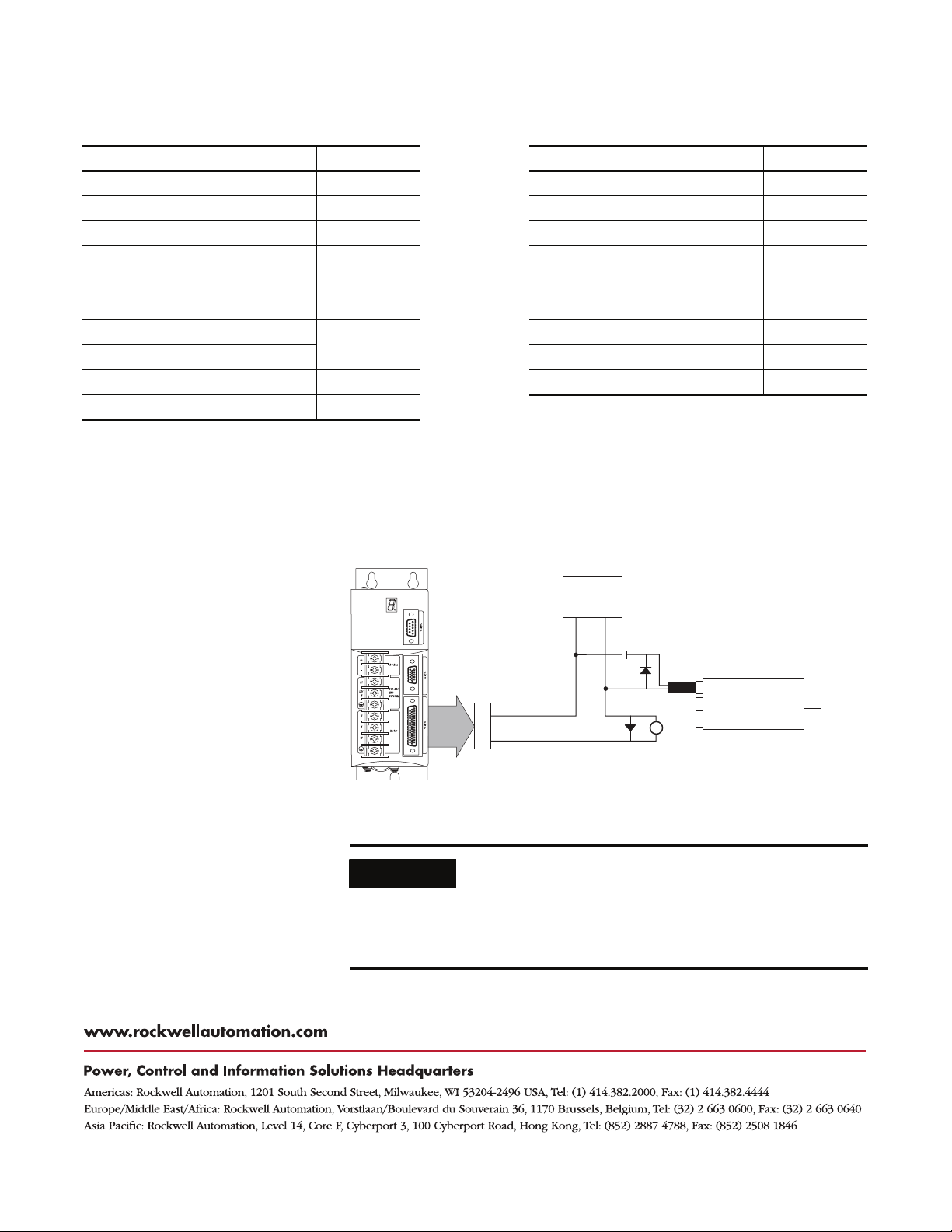
+12V dc
RS-232
Interface
COM
PC
RCV
XMT
Note: Pin-outs vary by manufacturer.
This example uses a B&B 485
adapter.
232 to 485
7
3
2
Replace Figure 2.57 on page 2-52 with the one shown below. The
new figure correctly identifies the drive connector as CN3.
Figure 2.57
RS-232 to RS-485 Connection Diagram
Common
Adapter
COM
RCV-
RCV+
XMT-
XMT+
7
5
17
3
14
1
RCV+
7
48
RCV- XMT+
CN3
Drive 1
XMT-
1
RCV+
7
48
RCV- XMT+
CN3
Drive 2
XMT-
1
RCV+
7
48
RCV- XMT+
CN3
Drive n
XMT-
Page 4-3
Error
Code
E02 Velocity exceeds position rollover /2
E03 Absolute feedback range exceeded
E44
Problem or Symptom Possible Cause Action/Solution
Lost motion fault
(only applies to applications with
Stegmann feedback devices)
Update the Error Codes table beginning on page 4-3 with the
following entries:
• Replace the error code entry for E02. In the new entry, the
reference to firmware revisions prior to 1.10 is removed.
• Replace the error code entry for E03. In the new entry, the
reference to firmware revisions prior to 1.10 is added.
• Add the lost motion fault (E44).
Error Codes
The velocity command or feedback exceeds
half the machine cycle length per
millisecond (applies only when the
machine cycle position rollover is enabled).
The motor position exceeds +/- 2047
revolutions from the home position (applies
only to systems with absolute feedback).
Detection occurs during a fault reset.
Absolute position in the drive is incorrect
and the motion has been lost due to line
loss condition.
Increase machine cycle size or reduce
velocity profile.
• Decrease application range of motion.
• Upgrade firmware.
This error only applies to firmware
revisions prior to 1.10.
• Cycle power.
• Cycle power and re-home drive if drive
was homed in the same power cycle
that the lost motion fault occurred.
Publication 2098-DU003B-EN-P — September 2006
Page 7
Ultra3000 Digital Servo Drive Installation Manual 3
Page A-2
Specification
AC input voltage
AC input frequency 47...63 Hz
AC input current
Continuous output current (0-pk) 2.5 A 5 A 10 A
Intermittent output current (0-pk) 7.5 A 15 A 30 A
Bus capacitance 1410 μF 1880 μF 1880 μF
Internal shunt resistance N/A N/A N/A
Shunt on N/A N/A N/A
Shunt off N/A N/A N/A
Bus overvoltage 400V dc 400V dc 400V dc
Energy absorption capability
Continuous power output
(1)
(2)
(3)
(4)
Replace the Ultra3000 (230V) Power Specifications table on page A-2
with the one shown below. The new table includes inrush current
specifications configured as Series A, B, or C.
• Ultra3000 drive firmware revision 1.45 is required to support the
Series C hardware.
• Ultraware software, version 1.63, is required to download
firmware to Series C drives containing the new power board.
Ultra3000 Drive (230V) Power Specifications
2098-DSD-005x-xx, 2098-DSD-010x-xx, and 2098-DSD-020x-xx
Description
2098-DSD-005 2098-DSD-010 2098-DSD-020
(1)
(2) (3)
Nom (rms)
230V ac (0-pk) max inrush
115V ac input
230V ac input
115V ac input
230V ac input
Specification is for nominal voltage. The absolute limits are ±10%, or 88...265V rms.
The 2098-DSD-005x-xx, -010x-xx, and -020x-xx (230V) drives are limited to:
Series A or B - one contactor cycle every two minutes.
Series C - one contactor cycle every 10 s for up to two minutes, not to exceed 12 cycles in five minutes.
Power initialization requires a short period of inrush current. Dual-element time delay (slow blow) fuses are recommended.
Inrush current-limiting circuitry is enabled within 3 s after removal of ac line power.
(4)
100...240V rms single-phase
5 A
100 A - Series A or B
20 A - Series C
93 J
38 J
0.25 kW
0.5 kW
9 A
100 A - Series A or B
20 A - Series C
125 J
51 J
0.5 kW
1.0 kW
18 A
100 A - Series A or B
20 A - Series C
1.0 kW
2.0 kW
ATTENTION
The inrush current-limiting circuitry is limited in the number of
power cycles it can withstand within a set period of time. If you
exceed these limitations, the circuitry will be damaged.
Publication 2098-DU003B-EN-P — September 2006
Page 8
4 Ultra3000 Digital Servo Drive Installation Manual
Page A-3
Replace the Ultra3000 (230V) Power Specifications table on page A-3
with the one shown below. The new table includes an updated value
in the bus capacitance field for 2098-DSD-030 drives.
Ultra3000 Drive (230V) Power Specifications
2098-DSD-030x-xx, 2098-DSD-075x-xx, and 2098-DSD-150x-xx
Specification
AC input voltage
(1)
2098-DSD-030 2098-DSD-075 2098-DSD-150
100...240V rms
Single-phase
AC input frequency 47...63 Hz
Main ac input current
Nom (rms)
230V ac (0-pk) Max inrush
(2) (3)
28 A
50 A
Auxiliary ac Input current
115V ac (rms) Nom
230V ac (rms) Nom
115V ac (0-pk) Max inrush
230V ac (0-pk) Max inrush
(4)
(4)
1.0 A
0.5 A
47 A
95 A
Continuous output current (0-pk) 15 A 35 A 65 A
Intermittent output current (0-pk) 30 A 75 A 150 A
Bus capacitance 2820 μF 4290 μF 7520 μF
Internal shunt resistance 35 Ω 16.5 Ω 9.1 Ω
Shunt on 420V dc 420V dc 420V dc
Shunt off 402V dc 402V dc 402V dc
Bus overvoltage 452V dc 452V dc 452V dc
Internal shunt
Continuous power
Peak power
50 W
4.5 kW
External shunt
Resistance
Continuous power
Peak power
30 Ω (-0/+5%)
2.4 kW
6 kW
Energy absorption capability
115V ac input
230V ac input
211 J
117 J
Continuous power output
115V ac input
230V ac input
(1)
Specification is for nominal voltage. The absolute limits are ±10%, or 88...265V rms.
(2)
The 2098-DSD-030x-xx, -075x-xx, and -150x-xx (230V) drives are limited to one contactor cycles per two minutes.
(3)
Power initialization requires a short period of inrush current. Dual-element time delay (slow blow) fuses are recommended.
(4)
400 μs half wave sine.
1.5 kW
3 kW
Description
100...240V rms
Three-phase
30 A
50 A
1.0 A
0.5 A
47 A
95 A
50 W
10 kW
16.5 Ω (-0/+5%)
4 kW
10 kW
381 J
211 J
3.75 kW
7.5 kW
46 A
68 A
1.0 A
0.5 A
47 A
95 A
180 W
18 kW
9 Ω (-0/+5%)
8 kW
19 kW
669 J
370 J
7.5 kW
15 kW
Publication 2098-DU003B-EN-P — September 2006
ATTENTION
The inrush current-limiting circuitry is limited in the number of
power cycles it can withstand within a set period of time. If you
exceed these limitations, the circuitry will be damaged.
Page 9
Ultra3000 Digital Servo Drive Installation Manual 5
Page A-4
Add the attention statement (below) to the Ultra3000 (460V) Power
Specifications table on page A-4. The table didn’t change, however,
the warning applies to all Ultra3000 drives.
Ultra3000 Drive (460V) Power Specifications
2098-DSD-HV030x-xx, -HV050x-xx, -HV100x-xx, -HV150x-xx, and -HV220x-xx
Specification
AC Input Voltage
AC Input Frequency 47...63 Hz
Main AC Input Current
460V ac (rms) Nom
460V ac (rms) Max inrush
Auxiliary AC Input Current
230V ac (rms) Nom
360V ac (rms) Nom
480V ac (rms) Nom
230V ac (0-pk) Max inrush
480V ac (0-pk) Max inrush
Continuous Output Current (0-pk) 7 A 11 A 23 A 34 A 47 A
Intermittent Output Current (0-pk) 14 A 22 A 46 A 68 A 94 A
Bus Capacitance 470 μF 705 μF 940 μF 1880 μF
Internal Shunt Resistance 120 Ω 40 Ω 25 Ω 20 Ω
Shunt On 800V dc
Shunt Off 750V dc
Bus Overvoltage 810V dc
Internal Shunt
Continuous power
Peak power
External Shunt
Resistance (-0/+5%)
Continuous power
Peak power
Energy Absorption Capability
230V ac input with 230V motor
230V ac input with 460V motor
460V ac input
Continuous Power Output
230V ac input
460V ac input
(1)
Specification is for nominal voltage. The absolute limits are ±10%, or 207...528V rms.
(2)
The 2098-DSD-HVxxx-xx drives can be powered with 230-240 V rms in order to be used in conjunction with motors designed for 230V operation. In such cases, the voltage
levels used for shunting and DC bus overvoltage limits are adjusted to be compatible with the voltage limit of the motor.
(3)
The 2098-DSD-HVxxx -xx (460V) drives are limited to three contactor cycles per minute.
(4)
Power initialization requires a short period of inrush current (processor controlled via soft start circuitry). Dual element time delay (slow blow) fuses are recommended
(refer to Fuse Specifications on page 6-8).
(5)
400 μs half wave sine.
(1) (2)
(3) (4)
(5)
(5)
2098-DSD-HV030 2098-DSD-HV050 2098-DSD-HV100 2098-DSD-HV150 2098-DSD-HV220
230...480V rms
Three-phase
4 A
6 A
0.55 A
0.35 A
0.25 A
47 A
68 A
100 W
5.3 kW
120 Ω
3 kW
5.3 kW
15 J
129 J
55 J
1.5 kW
3.0 kW
7 A
6 A
2.5 kW
5.0 kW
Description
14 A
6 A
200 W
16 kW
40 Ω
10 kW
16 kW
22 J
194 J
82 J
5.0 kW
10 kW
20 A
6 A
200 W
25.6 kW
25 Ω
15 kW
25.6 kW
29 J
259 J
109 J
7.5 kW
15 kW
28 A
6 A
400 W
32 kW
20 Ω
22 kW
32 kW
59 J
517 J
219 J
11 kW
22 kW
ATTENTION
The inrush current-limiting circuitry is limited in the number of
power cycles it can withstand within a set period of time. If you
exceed these limitations, the circuitry will be damaged.
Publication 2098-DU003B-EN-P — September 2006
Page 10
6 Ultra3000 Digital Servo Drive Installation Manual
Page B-2
Note: Information:
May be used to maintain power to logic section of drive and status LED indicators when main ac input power is removed. A separate ac line
6
source may be used if voltage is between 88-265V ac (rms) on 2098-DSD-xxx (230V drives) or 207-528V ac (rms) on 2098-DSD-HVxxx (460V
drives). In this configuration, a separate line filter for logic power may be required.
Place the ac (EMC) line filter as close to the drive as possible and do not route very dirty wires in wireway (refer to Establishing Noise Zones, on
7
page 1-13). If routing in wireway is unavoidable, use shielded cable with shields grounded to the drive chassis and filter case. For ac line filter
specifications, refer to AC Line Filter Specifications in Appendix A.
Page B-4
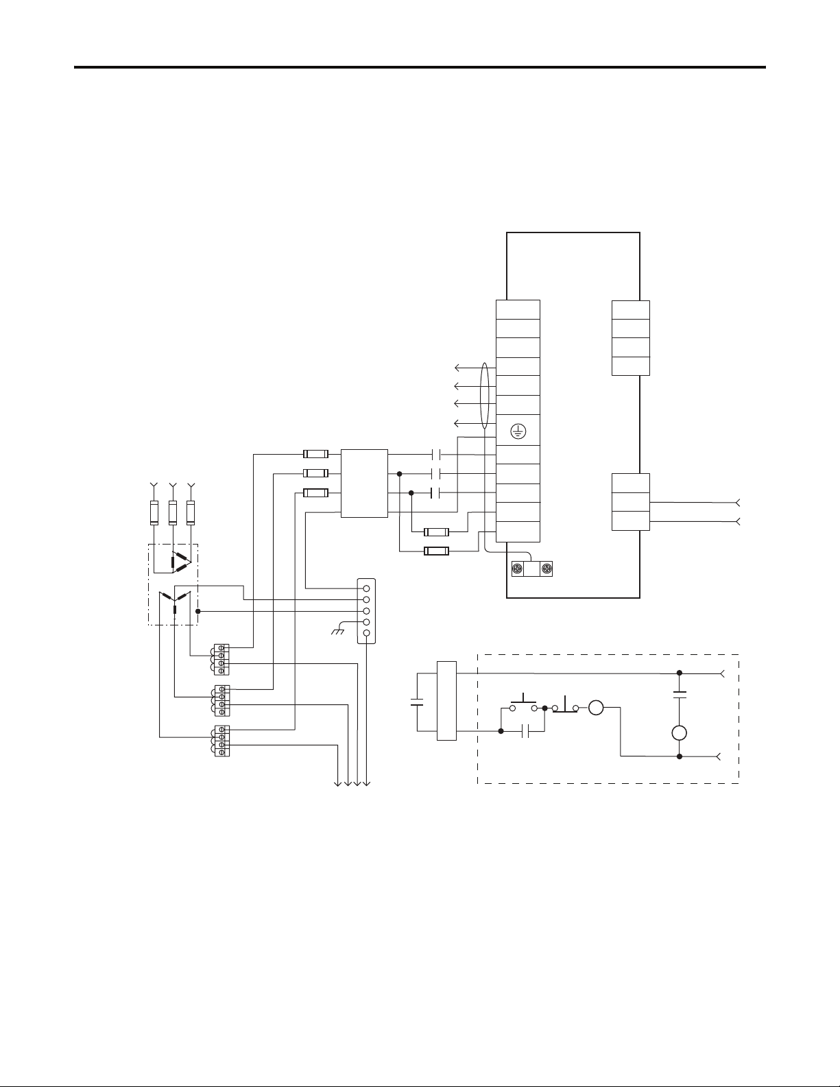
Replace notes 6 and 7 in the Ultra3000 Interconnect Diagram Notes
with the ones shown below. The new versions include information
regarding the placement of ac line filters and routing of wires.
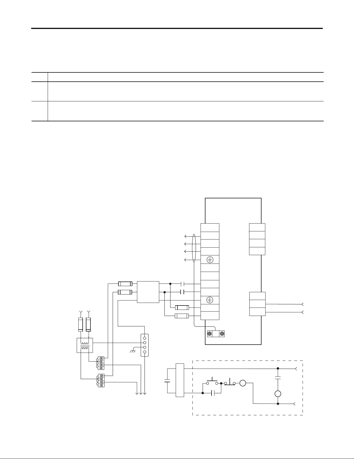
Replace the interconnect diagram on page B-4 with the one shown
below. The new diagram changes the recommended wiring of input
fusing, ac line filter, and contactor.
Figure B.2
Typical Power Wiring of Ultra3000 System
(2098-DSD-030x-xx)
Ultra3000
Digital Servo Drive
2098-DSD-030x-xx
Note 13
Fused Disconnect
or Circuit Breaker *
Note 1
Isolation
Transformer *
Note 2
Single-phase Input
100-240V ac (rms)
Single-phase AC Line
50/60 Hz
L1
L2/N
Chassis
Ter min al
Blocks *
Note 3
Input Fusing *
Note 4, 5
Bonded Cabinet
Ground Bus *
Single-phase
AC Line Filter
Note 7
To additional
Ultra3000 drive.
Three-phase
Motor Power
Connections
Note 12
Note 6
Input Fusing *
CN1
M1 *
Note 8
Note 4, 5
43
43
44
44
TB1
U
V
W
DC+
DC-
L1
L2/N
L1 AUX
L2/N AUX
START *
CR1 *
Motor Power
Connections
AC Input Power
Connections
Cable Shield
Clamp
Note 9
STOP *
CR1 *
TB2
1
2
3
CN1
43
44
External Passive
Shunt Connections
N.O. Relay Output+
N.O. Relay Output-
CR1 *
M1 *
Note 20
24V dc
* Indicates User Supplied Component
Publication 2098-DU003B-EN-P — September 2006
Refer to Attention statement (Notes 10, 11)
Page 11
Ultra3000 Digital Servo Drive Installation Manual 7
Page B-5
Fused Disconnect
or Circuit Breaker *
Note 1
Isolation
Tra nsfo rme r *
Note 2
Three-phase AC Line
50/60 Hz
Neutral
Chassis
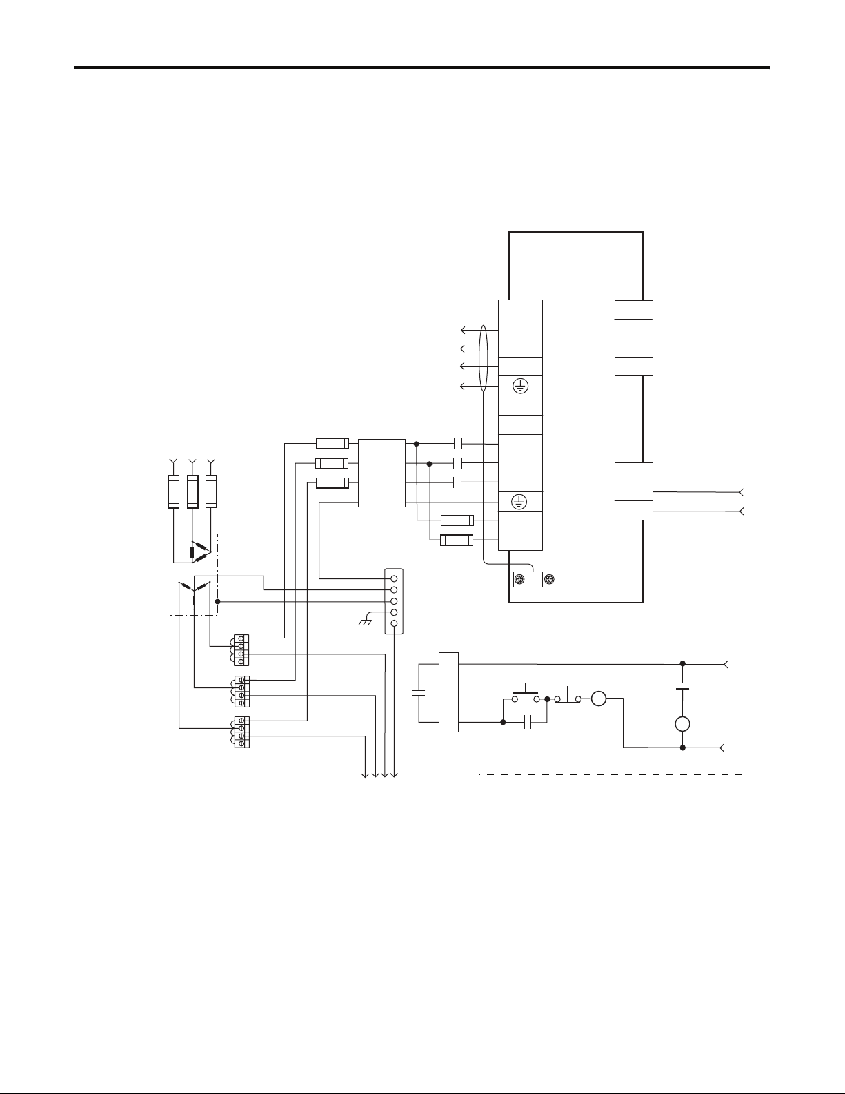
Replace the interconnect diagram on page B-5 with the one shown
below. The new diagram changes the recommended wiring of input
fusing, ac line filter, and contactor.
Figure B.3
Typical Power Wiring of Ultra3000 System
(2098-DSD-075x-xx and -150x-xx)
Ultra3000
Digital Servo Drives
2098-DSD-075x-xx and
-150x-xx
Note 13
TB2
1
2
3
CN1
43
44
External Passive
Shunt Connections
N.O. Relay Output+
N.O. Relay Output-
Note 20
Input Fusing *
Note 4, 5
Three-phase
AC Line Filter
Note 7
Three-Phase
Motor Power
Connections
Note 6
Bonded Cabinet
Ground Bus *
Note 12
M1 *
Note 8
Input Fusing *
Note 4, 5
TB1
U
V
W
DC+
DC-
L1
L2
L3
L1 AUX
L2/N AUX
Motor Power
Connections
AC Input Power
Connections
Cable Shield
Clamp
Note 9
Three-phase Input
100-240V ac (rms)
L2
L3
* Indicates User Supplied Component
L1
Terminal
Blocks *
Note 3
To additional
Ultra3000 drive.
CN1
43
43
44
44
CR1 *
STOP *
CR1 *
CR1 *
M1 *
START *
Refer to Attention statement (Notes 10, 11)
24V dc
Publication 2098-DU003B-EN-P — September 2006
Page 12
8 Ultra3000 Digital Servo Drive Installation Manual
Page B-6
Fused Disconnect
or Circuit Breaker *
Note 1
Isolation
Transformer *
Note 2
Three-phase AC Line
50/60 Hz
Neutral
Chassis
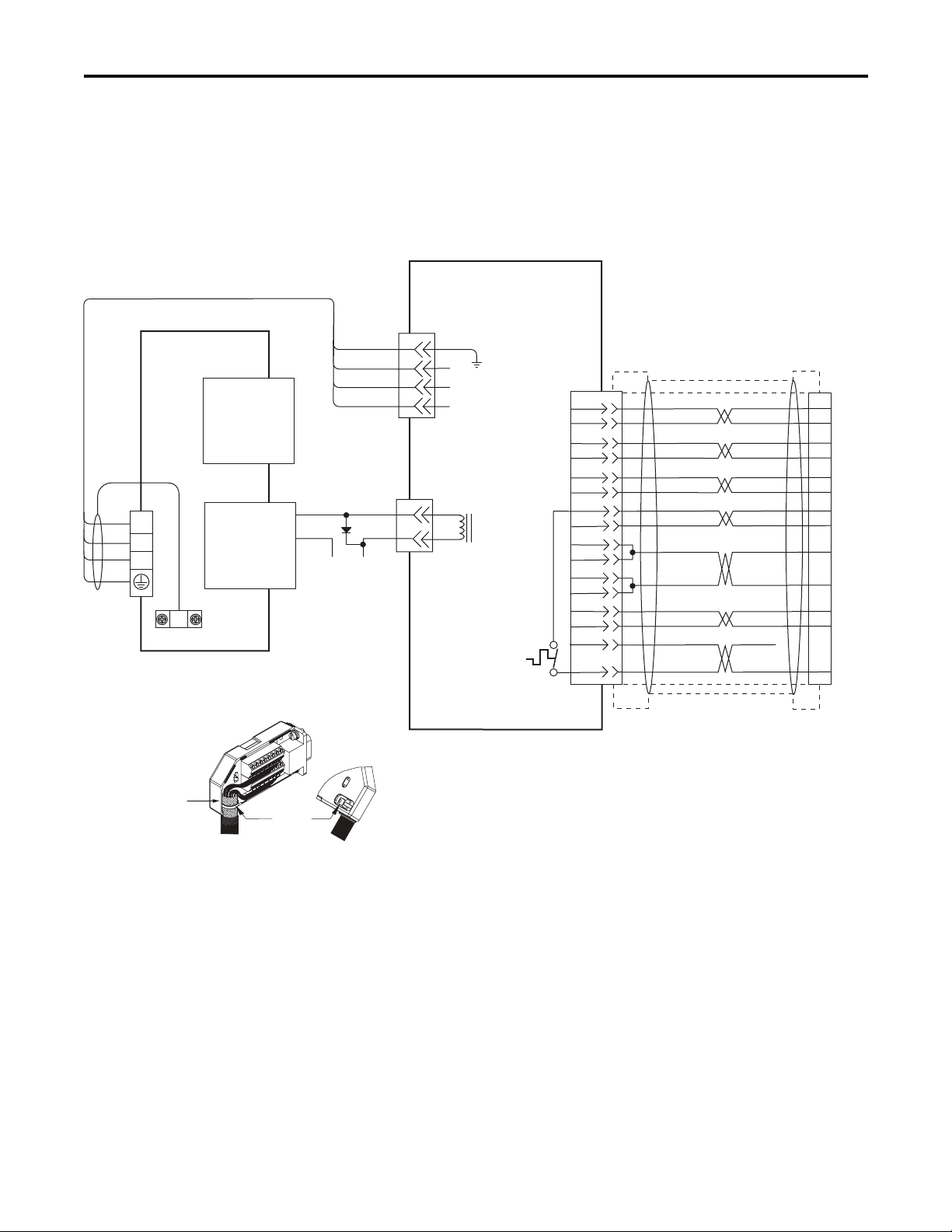
Replace the interconnect diagram on page B-6 with the one shown
below. The new diagram changes the recommended wiring of input
fusing, ac line filter, and contactor.
Figure B.4
Typical Power Wiring of Ultra3000 System
(2098-DSD-HVxxx-xx and -HVxxxX-xx)
Ultra3000
Digital Servo Drives
2098-DSD-HVxxx-xx and
-HVxxxX-xx
Note 14
TB2
1
2
3
CN1
43
44
External Passive
Shunt Connections
N.O. Relay Output+
N.O. Relay Output-
Input Fusing *
Notes 4 and 5
Three-phase
AC Line Filter
Note 7
Note 6
Three-phase
Motor Power
Connections
Input Fusing*
Notes 4 and 5
Bonded Cabinet
Ground Bus *
Note 12
M1 *
Note 8
TB1
DC+
DC-
W
V
U
L3
L2
L1
L1 AUX
L2/N AUX
Motor Power
Connections
AC Input Power
Connections
Cable Shield
Clamp
Note 9
Note 20
L3
Three-phase Input
230-480V ac (rms)
L2
L1
Terminal Blocks *
Note 3
* Indicates User Supplied Component
Publication 2098-DU003B-EN-P — September 2006
To additional
Ultra3000 drive.
CN1
43
43
44
44
CR1 *
STOP *
CR1 *
CR1 *
M1 *
START *
Refer to Attention statement (Notes 10, 11)
24V dc
Page 13
Ultra3000 Digital Servo Drive Installation Manual 9
Page B-12
Ultra3000 Drive
BRN
U
BLK
V
BLU
W
GN/YL
Notes 13, 14
Motor Feedback
(15-pin) Connector
Control Interface
(44-pin) Connector
CN2
CN1
Note 19
43
44
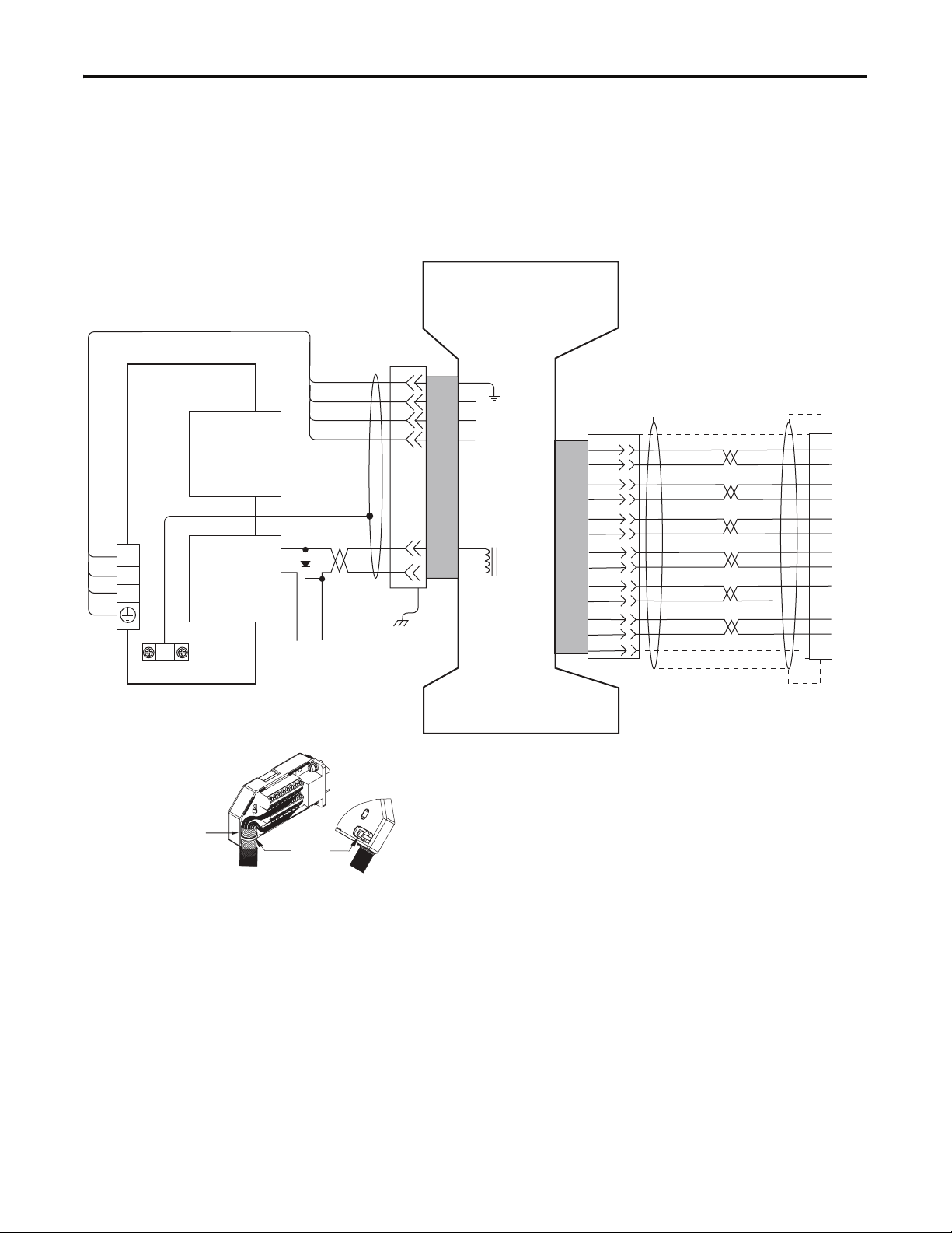
Replace Figure B.12 on page B-12 with the one shown below. The
new figure includes MP-Series food grade (MPF), stainless steel (MPS)
and low inertia (MPL-A/B15xx and MPL-A/B2xx) motors. Also
included is an illustration of grounding the feedback cable shield.
Figure B.12
Ultra3000 Drive to MP-Series (MPL-A/B, MPF-A/B, and MPS-A/B) Motors
MPL-A/B15xx and -A/B2xx,
MPF-A/Bxxx and MPS-A/Bxxx
Servo Motors with
High Resolution Feedback
Green/Yellow
Blue
Black
Brown
2090-XXNPMF-xxSxx
Motor Power Cable
Note 12
Black
White
D/
C/W
B/V
A/U
G/-
F/+
W
V
Three-Phase
U
Motor Power
Motor Feedback
BR-
BR+
Thermostat
GND
Motor
Brake
1
2
3
4
5
6
9
10
11
13
14
BLACK
WHT/BLACK
RED
WHT/RED
GREEN
WHT/GREEN
GRAY
WHT/GRAY
ORANGE
WHT/ORANGE
BLUE
Motor Feedback
(CN2) Connector
SIN+
SIN-
COS+
COS-
DATA+
DATA-
+5VDC
ECOM
+9VDC
TS+
TS-
1
2
3
4
5
10
14
6
7
11
Motor
Power
TB1
Grounding Technique for
Feedback Cable Shield
Exposed shield secured
under clamp.
Motor Feedback Breakout Board
Cable Shield
Clamp
Note 9
+24V dc Power Supply
(2090-UXBB-DM15)
COM
User Supplied
(1.0 A max)
Cable Tie
+24V
MPL-A/B15xx and -A/B2xx
Servo Motors with
Incremental Feedback
D/
C/W
B/V
A/U
W
Three-Phase
V
Motor Power
U
Motor Feedback
Thermostat
G/-
F/+
BR-
BR+
GND
Motor
Brake
12
Refer to illustration (lower left)
for proper grounding technique.
2090-XXNFMF-Sxx
(flying-lead) Feedback Cable
Notes 12, 16, 18
COM
Motor Feedback
(CN2) Connector
1
2
3
4
5
6
9
10
11
13
14
15
16
17
12
BLACK
WHT/BLACK
RED
WHT/RED
GREEN
WHT/GREEN
GRAY
WHT/GRAY
ORANGE
WHT/ORANGE
BLUE
WHT/BLUE
YELLOW
WHT/YELLOW
AM+
AM-
BM+
BM-
IM+
IM-
+5VDC
ECOM
–
TS+
TS-
S1
S2
S3
COM
1
2
3
4
5
10
14
6
11
12
13
8
Refer to illustration (lower left)
for proper grounding technique .
2090-XXNFMF-Sxx Feedback Cable
Note 12, 16
Publication 2098-DU003B-EN-P — September 2006
Page 14
10 Ultra3000 Digital Servo Drive Installation Manual
Page B-13
2090-XXNPH/HF-xxSxx or -UXNPBH/HF-xxSxx
Ultra3000 230V Drive
BRN
U
BLK
V
BLU
W
GN/YL
Motor
Power
TB1
Motor Power Cable
Note 12
Note 13
Motor Feedback
(15-pin) Connector
Control Interface
(44-pin) Connector
Cable Shield
Clamp
Note 9
CN2
9101-0330 Brake Cable Connector Kit
43
44
CN1
User Supplied
+24V dc Power Supply
Replace Figure B.13 on page B-13 with the one shown below. The
new figure correctly identifies the motor brake-connector pins as A
and B. Also included is an illustration of grounding the feedback cable
shield.
Figure B.13
Ultra3000 Drive to H- and F-Series (230V) Motors
H- or F-Series (230V)
Servo Motors with
Incremental Feedback
Green/Yellow
Brown
Note 12
Note 19
+24V
COM
(1.0 A max)
Blue
Black
Black
White
D
W
C
V
B
U
A
B
BR-
A
BR+
GND
Three-Phase
Motor Power
Motor Feedback
Motor Brake
Thermostat
A
B
C
D
E
F
R
P
K
J
L
M
N
T
H
S
BLACK
WHT/BLACK
RED
WHT/RED
GREEN
WHT/GREEN
WHT/BROWN
BROWN
GRAY
WHT/GRAY
BLUE
WHT/BLUE
VIOLET
WHT/VIOLET
Motor Feedback
(CN2) Connector
AM+
AM-
BM+
BM-
IM+
IM-
TS+
S3
+5VDC
ECOM
S2
S1
–
TS-
1
2
3
4
5
10
11
8
14
6
13
12
6
Grounding Technique for
Feedback Cable Shield
Exposed shield secured
under clamp.
Motor Feedback Breakout Board
(2090-UXBB-DM15)
Cable Tie
Refer to illustration (lower left)
for proper grounding technique.
2090-XXNFHF-Sxx (flying lead)
or 2090-UXNFBHF-Sxx (with drive-end con nector)
Feedback Cable
Notes 12, 15, 16
Publication 2098-DU003B-EN-P — September 2006
Page 15
Ultra3000 Digital Servo Drive Installation Manual 11
Page B-15
Ultra3000 230V Drive
1-BLK
U
2-BLK
V
3-BLK
W
GN/YL
Motor
Power
TB1
Grounding Technique for
Feedback Cable Shield
Note 13
Motor Feedback
(15-pin) Connector
CN2
Control Interface
(44-pin) Connector
CN1
Cable Shield
Clamp
Note 9
Replace Figure B.15 on page B-15 with the one shown below. The
new figure correctly identifies the motor power-cable pins as 1, 2, 3,
and 5. Also included is an illustration of grounding the feedback cable
shield.
Figure B.15
Ultra3000 Drive to Y-Series (230V) Motors
Green/Yellow
3/Black
2/Black
1/Black
2090-XXNPY-16Sxx
Motor Power Cable
Note 12
43
44
Note 19
COM
+24V dc Power Supply
+24V
User Supplied
(1.0 A max)
BLK
BLK
Y-Series (230V)
Servo Motors with
Incremental Feedback
5
Pigtail
W
V
Three-Phase
U
Motor Power
BR-
BR+
GND
Motor
Feedback
Motor
Brake
Pigtail
9
10
11
12
13
14
15
17
19
–
22
23
BLACK
WHT/BLACK
RED
WHT/RED
GREEN
WHT/GREEN
WHT/BLUE
BLUE
BROWN
WHT/BROWN
GRAY
WHT/GRAY
3
2
1
9
7
24
Refer to illustration (lower left)
for proper grounding techniq ue.
2090-XXNFY-Sxx (flying lead)
or 2090-UXNFBY-Sxx (with drive-end connector)
Feedback Cable
Notes 12, 15, 16
AM+
AM-
BM+
BM-
IM+
IM-
S1
S2
S3
–
+5VDC
ECOM
DRAIN
Motor Feedback
(CN2) Connector
1
2
3
4
5
10
12
13
8
14
6
Exposed shield secured
under clamp.
Motor Feedback Breakout Board
Cable Tie
(2090-UXBB-DM15)
Publication 2098-DU003B-EN-P — September 2006
Page 16
Page B-19
Replace the table on page B-19 with the one shown below. The new
table includes the MPL-x15xx, MPL-x2xx, and TL-Series motors.
Compatible Brake Motors Coil Current Compatible Brake Motors Coil Current
MPL-x15xx
MPL-x2xx
MPL/MPF/MPS-x310, -x320, -x330
(1)
(1)
(1)
MPL-x420, -x430, -x4520, -x4530, -x4540
MPF-x430, -x4530, -x4540
MPG-x004
MPG-x010
MPG-x025
MPG-x050
MPG-x110
(1)
(1)
(1)
(1)
(1)
(1)
Applies to 230V and 460V motors.
(1)
0.48 A 1326AB-B4xxx 0.88 A
0.51 A F-4030, -4050, and -4075 0.69 A
0.50 A Y-1002 and -1003 0.26 A
(1)
0.64 A
Y-2006 and -2012 0.31 A
Y-3023 0.37 A
0.33 A TL-A110P-H, -A120P-H, and -A130P-H 0.208 A
0.45 A
TL-A220P-H and -A230P-H 0.375 A
TL-A2530P-H and -A2540P-H 0.396 A
0.50 A TL-A410P-H 0.746 A
1.0 A
Replace Figure B.19 with the one shown below. The new figure
correctly identifies the relay output pins as CN1-43 and CN1-44.
Figure B.19
Example Configuration Controlling a Motor Brake
Power Supply
Ultra3000 Drive
N.O. Relay Output +
43
CN1
(1)
Flyback diode (1N4004 rated 1.0 A @ 400V dc) or MOV suppresses the collapsing field of the brake coil.
(2)
For non-SERCOS drive, the relay output (CN1-43 and -44) must be configured as a brake.
IMPORTANT
N.O. Relay Output +
44
Electrical arcing may occur at the relay contacts until the brake
3 A @ 24V dc
_
+
(2)
(1)
CR1
(1)
CR1
Brake
Feedback
Power
Servo
Motor
power dissipates. A customer-supplied diode or metal oxide
varistor (MOV) is recommended to prevent arcing. Use of an
MOV can also reduce the time to mechanically engage the
brake.
Allen-Bradley, Rockwell Automation, and Ultra3000 are trademarks of Rockwell Automation, Inc.
Trademarks not belonging to Rockwell Automation are property of their respective companies.
Publication 2098-DU003B-EN-P — September 200612 PN 0013-2069-002
Supersedes Publication 2098-DU 003A-EN-P — June 2005 Copyright © 2006 Rockwell Automation, Inc. All rights reserv ed. Printed in the U.S.A.
Page 17

Table of Contents
Preface
Installing Your Ultra3000
Introduction . . . . . . . . . . . . . . . . . . . . . . . . . . . . . . . . . . . P-1
Who Should Use this Manual . . . . . . . . . . . . . . . . . . . . . . . P-1
Purpose of this Manual . . . . . . . . . . . . . . . . . . . . . . . . . . . P-1
Contents of this Manual . . . . . . . . . . . . . . . . . . . . . . . . . . . P-2
Product Receiving and Storage Responsibility . . . . . . . . . . . P-2
Related Documentation . . . . . . . . . . . . . . . . . . . . . . . . . . . P-3
Conventions Used in this Manual . . . . . . . . . . . . . . . . . . . . P-4
Allen-Bradley Support . . . . . . . . . . . . . . . . . . . . . . . . . . . . P-4
Local Product Support . . . . . . . . . . . . . . . . . . . . . . . . . P-4
Technical Product Assistance . . . . . . . . . . . . . . . . . . . . P-4
Comments Regarding this Manual . . . . . . . . . . . . . . . . . P-4
Chapter 1
Chapter Objectives. . . . . . . . . . . . . . . . . . . . . . . . . . . . . . . 1-1
Complying with European Union Directives . . . . . . . . . . . . 1-2
EMC Directive . . . . . . . . . . . . . . . . . . . . . . . . . . . . . . . 1-2
Meeting CE Requirements . . . . . . . . . . . . . . . . . . . . . . . 1-2
Low Voltage Directive. . . . . . . . . . . . . . . . . . . . . . . . . . 1-3
Ultra3000 System Component Overview . . . . . . . . . . . . . . . 1-3
Before Mounting Your System . . . . . . . . . . . . . . . . . . . . . . 1-5
Unpacking Modules . . . . . . . . . . . . . . . . . . . . . . . . . . . 1-5
System Mounting Requirements. . . . . . . . . . . . . . . . . . . 1-6
Ventilation Requirements . . . . . . . . . . . . . . . . . . . . . . . 1-7
Sizing an Enclosure . . . . . . . . . . . . . . . . . . . . . . . . . . . 1-8
Transformer Sizing . . . . . . . . . . . . . . . . . . . . . . . . . . . . 1-8
Fuse Sizing. . . . . . . . . . . . . . . . . . . . . . . . . . . . . . . . . 1-10
HF Bonding Your System . . . . . . . . . . . . . . . . . . . . . . . . 1-10
Bonding Modules . . . . . . . . . . . . . . . . . . . . . . . . . . . . 1-11
Bonding Multiple Subpanels . . . . . . . . . . . . . . . . . . . . 1-12
Planning Your Panel Layout . . . . . . . . . . . . . . . . . . . . . . . 1-12
Establishing Noise Zones . . . . . . . . . . . . . . . . . . . . . . 1-13
Cable Categories for the Ultra3000. . . . . . . . . . . . . . . . 1-14
Mounting Guidelines to Reduce Electrical Noise . . . . . 1-15
Mounting Your Ultra3000 Drive . . . . . . . . . . . . . . . . . . . . 1-18
Chapter 2
Ultra3000 Connector Data
i Publication 2098-IN003E-EN-P — April 2004
Chapter Objectives. . . . . . . . . . . . . . . . . . . . . . . . . . . . . . . 2-1
Understanding Ultra3000 Connectors . . . . . . . . . . . . . . . . . 2-1
Ultra3000 Front Panel Connections . . . . . . . . . . . . . . . . 2-2
Ultra3000 (with SERCOS) Front Panel Connections. . . . 2-10
Ultra3000 (with DeviceNet) Front Panel Connections . . 2-18
Understanding Ultra3000 I/O Specifications . . . . . . . . . . . 2-26
Digital I/O Power Supply . . . . . . . . . . . . . . . . . . . . . . 2-26
Auxiliary 5V Logic Supply . . . . . . . . . . . . . . . . . . . . . . 2-26
Digital Inputs . . . . . . . . . . . . . . . . . . . . . . . . . . . . . . . 2-28
Digital Outputs. . . . . . . . . . . . . . . . . . . . . . . . . . . . . . 2-33
Analog COMMAND Input . . . . . . . . . . . . . . . . . . . . . . 2-37
Page 18

ii Table of Contents
Analog ILIMIT Input . . . . . . . . . . . . . . . . . . . . . . . . . . 2-38
Analog Output . . . . . . . . . . . . . . . . . . . . . . . . . . . . . . 2-39
Understanding Motor Encoder Feedback Specifications . . . 2-40
AM, BM, and IM Inputs . . . . . . . . . . . . . . . . . . . . . . . . 2-40
Hall Inputs . . . . . . . . . . . . . . . . . . . . . . . . . . . . . . . . . 2-42
Thermostat Input . . . . . . . . . . . . . . . . . . . . . . . . . . . . 2-42
+ Limit and - Limit Inputs . . . . . . . . . . . . . . . . . . . . . . 2-43
Encoder Phasing . . . . . . . . . . . . . . . . . . . . . . . . . . . . . 2-44
Motor Encoder Connection Diagram . . . . . . . . . . . . . . 2-45
Understanding Motor Feedback Signals and Outputs . . . . . 2-46
Unbuffered Encoder Outputs. . . . . . . . . . . . . . . . . . . . 2-46
Incremental Encoder Output . . . . . . . . . . . . . . . . . . . . 2-47
High Resolution Encoder Output . . . . . . . . . . . . . . . . . 2-48
Understanding Auxiliary Encoder Feedback Specifications . 2-49
5V Auxiliary Encoder Power Supply . . . . . . . . . . . . . . 2-51
Understanding the Serial Interface. . . . . . . . . . . . . . . . . . . 2-51
Default Serial Interface Settings . . . . . . . . . . . . . . . . . . 2-52
Multiple Axes RS-232 Communications. . . . . . . . . . . . . 2-52
Four-Wire RS-485 Connections . . . . . . . . . . . . . . . . . . 2-53
Restoring Drive Communications. . . . . . . . . . . . . . . . . 2-54
Connecting Your Ultra3000
Chapter 3
Chapter Objectives. . . . . . . . . . . . . . . . . . . . . . . . . . . . . . . 3-1
Understanding Basic Wiring Requirements . . . . . . . . . . . . . 3-1
Building Your Own Cables . . . . . . . . . . . . . . . . . . . . . . 3-2
Routing Power and Signal Wiring . . . . . . . . . . . . . . . . . 3-2
Determining Your Type of Input Power . . . . . . . . . . . . . . . 3-3
Three-Phase Power Wired to Three-Phase Drives . . . . . . 3-3
Single-Phase Power Wired to Single-Phase Drives . . . . . 3-5
Three-Phase Power Wired to Single-Phase Drives. . . . . . 3-6
Grounding Your Ultra3000 . . . . . . . . . . . . . . . . . . . . . . . . . 3-9
Grounding Your System to the Subpanel . . . . . . . . . . . . 3-9
Grounding Multiple Subpanels . . . . . . . . . . . . . . . . . . 3-10
Motor Power Cable Shield Termination . . . . . . . . . . . . 3-10
Power Wiring Requirements . . . . . . . . . . . . . . . . . . . . . . . 3-13
Connecting Input Power. . . . . . . . . . . . . . . . . . . . . . . . . . 3-16
Connecting Motor Power and Brakes . . . . . . . . . . . . . . . . 3-18
Applying the Motor Cable Shield Clamp. . . . . . . . . . . . 3-18
Wiring Motor Power . . . . . . . . . . . . . . . . . . . . . . . . . . 3-19
Understanding Motor Brake Connections . . . . . . . . . . . 3-21
Understanding Shunt Connections . . . . . . . . . . . . . . . . . . 3-22
Understanding Feedback and I/O Cable Connections . . . . 3-23
Motor Feedback Connector Pin-outs . . . . . . . . . . . . . . 3-24
Connecting Your SERCOS Fiber-Optic Cables . . . . . . . . . . 3-26
Connecting to a DeviceNet Network . . . . . . . . . . . . . . . . . 3-29
Connecting Your DeviceNet Cable. . . . . . . . . . . . . . . . 3-30
Publication 2098-IN003E-EN-P — April 2004
Page 19

Troubleshooting Status Indicators
Specifications and Dimensions
Table of Contents iii
Chapter 4
Chapter Objectives. . . . . . . . . . . . . . . . . . . . . . . . . . . . . . . 4-1
Safety Precautions . . . . . . . . . . . . . . . . . . . . . . . . . . . . . . . 4-2
General Troubleshooting . . . . . . . . . . . . . . . . . . . . . . . . . . 4-3
Error Codes . . . . . . . . . . . . . . . . . . . . . . . . . . . . . . . . . 4-3
Troubleshooting for SERCOS Drives . . . . . . . . . . . . . . . . . . 4-9
SERCOS Module Status LED . . . . . . . . . . . . . . . . . . . . . 4-9
SERCOS Network Status LED. . . . . . . . . . . . . . . . . . . . . 4-9
Troubleshooting for DeviceNet Drives . . . . . . . . . . . . . . . 4-10
DeviceNet Module Status LED . . . . . . . . . . . . . . . . . . . 4-10
DeviceNet Network Status LED . . . . . . . . . . . . . . . . . . 4-10
Appendix A
Chapter Objectives. . . . . . . . . . . . . . . . . . . . . . . . . . . . . . . A-1
Certifications . . . . . . . . . . . . . . . . . . . . . . . . . . . . . . . . . . . A-1
Ultra3000 Power Specifications. . . . . . . . . . . . . . . . . . . . . . A-2
Ultra3000 (230V) Power Specifications. . . . . . . . . . . . . . A-2
Ultra3000 (460V) Power Specifications. . . . . . . . . . . . . . A-4
Fuse Specifications . . . . . . . . . . . . . . . . . . . . . . . . . . . . A-5
Circuit Breaker Specifications . . . . . . . . . . . . . . . . . . . . A-6
Contactor Ratings . . . . . . . . . . . . . . . . . . . . . . . . . . . . . A-7
Power Dissipation Specifications . . . . . . . . . . . . . . . . . . A-7
Ultra3000 General Specifications. . . . . . . . . . . . . . . . . . . . . A-8
Physical and Environmental Specifications . . . . . . . . . . . A-8
Control Specifications . . . . . . . . . . . . . . . . . . . . . . . . . . A-8
Inputs and Outputs Specifications . . . . . . . . . . . . . . . . . A-9
Communication Specifications. . . . . . . . . . . . . . . . . . . . A-9
Motor Feedback Specifications . . . . . . . . . . . . . . . . . . A-10
Auxiliary Feedback Specifications . . . . . . . . . . . . . . . . A-10
Connector Specifications. . . . . . . . . . . . . . . . . . . . . . . A-10
AC Line Filter Specifications . . . . . . . . . . . . . . . . . . . . A-11
Ultra Family External Shunt Module Specifications . . . . A-12
Maximum Feedback Cable Lengths . . . . . . . . . . . . . . . A-13
Dimensions . . . . . . . . . . . . . . . . . . . . . . . . . . . . . . . . . . . A-14
Ultra3000 (230V) Dimensions . . . . . . . . . . . . . . . . . . . A-14
Ultra3000 (460V) Dimensions . . . . . . . . . . . . . . . . . . . A-16
Interconnect Diagrams
Appendix B
Chapter Objectives. . . . . . . . . . . . . . . . . . . . . . . . . . . . . . . B-1
Ultra3000 Interconnect Diagram Notes . . . . . . . . . . . . . . . . B-2
Power Interconnect Diagrams . . . . . . . . . . . . . . . . . . . . . . B-3
Shunt Module Interconnect Diagrams . . . . . . . . . . . . . . . . . B-7
Active Shunt Module Diagrams . . . . . . . . . . . . . . . . . . . B-7
Passive Shunt Module Diagrams . . . . . . . . . . . . . . . . . . B-7
Ultra3000/Motor Interconnect Diagrams . . . . . . . . . . . . . . B-10
Control String Examples (120V ac) . . . . . . . . . . . . . . . . . . B-16
Publication 2098-IN003E-EN-P — April 2004
Page 20

iv Table of Contents
Catalog Numbers and Accessories
Controlling a Brake Example . . . . . . . . . . . . . . . . . . . . . . B-19
Ultra3000 to Logix Cable and Interconnect Diagrams . . . . . B-20
Ultra3000 to IMC-S Compact Cable and
Interconnect Diagram . . . . . . . . . . . . . . . . . . . . . . B-23
Appendix C
Chapter Objectives. . . . . . . . . . . . . . . . . . . . . . . . . . . . . . . C-1
Ultra3000 Drives . . . . . . . . . . . . . . . . . . . . . . . . . . . . . . . . C-2
Software . . . . . . . . . . . . . . . . . . . . . . . . . . . . . . . . . . . . . . C-2
AC Line Filters . . . . . . . . . . . . . . . . . . . . . . . . . . . . . . . . . . C-3
External Shunt Kits. . . . . . . . . . . . . . . . . . . . . . . . . . . . . . . C-3
Cables . . . . . . . . . . . . . . . . . . . . . . . . . . . . . . . . . . . . . . . . C-4
Motor Power Cables . . . . . . . . . . . . . . . . . . . . . . . . . . . C-4
Motor Feedback Cables. . . . . . . . . . . . . . . . . . . . . . . . . C-5
MP-Series Motor Brake Cable . . . . . . . . . . . . . . . . . . . . C-5
Ultra3000 Interface Cables . . . . . . . . . . . . . . . . . . . . . . . C-5
SERCOS Interface Fiber-Optic Cables . . . . . . . . . . . . . . . C-6
Drive End Connector Kits . . . . . . . . . . . . . . . . . . . . . . . C-6
Motor End Connector Kits . . . . . . . . . . . . . . . . . . . . . . . C-7
Breakout Board Kits . . . . . . . . . . . . . . . . . . . . . . . . . . . C-8
Breakout Boards . . . . . . . . . . . . . . . . . . . . . . . . . . . . . . C-8
Breakout Cables . . . . . . . . . . . . . . . . . . . . . . . . . . . . . . C-8
Publication 2098-IN003E-EN-P — April 2004
Page 21

Preface
Introduction
Who Should Use this Manual
Read this preface to familiarize yourself with the rest of the manual.
This preface contains the following topics:
• Who Should Use this Manual
• Purpose of this Manual
• Contents of this Manual
• Product Receiving and Storage Responsibility
• Related Documentation
• Conventions Used in this Manual
• Allen-Bradley Support
Use this manual for designing, installing, and wiring your Ultra™3000
Digital Servo Drive (DSD). The manual is intended for engineers or
technicians directly involved in the installation and wiring of the
Ultra3000.
If you do not have a basic understanding of the Ultra3000, contact
your local Allen-Bradley representative for information on available
training courses before using this product.
Purpose of this Manual
1 Publication 2098-IN003E-EN-P — April 2004
This manual provides the mounting, wiring, and connecting
procedures for the Ultra3000 and standard Rockwell Automation/
Allen-Bradley motors recommended for use with the Ultra3000.
For power up procedures, troubleshooting tables, and system
integration with Ultraware or the ControlLogix
modules/PCI cards (see table below) refer to the Ultra3000 Digital
Servo Drives Integration Manual (publication 2098-IN005x-EN-P).
Manuals are available electronically (as a .pdf) or in hardcopy from
www.theautomationbookstore.com.
Interface
SERCOS interface™ 1756-MxxSE 1784-PM16SE
Analog interface 1756-M02AE 1784-PM02AE
ControlLogix Motion
Module
SoftLogix PCI Card
®
and SoftLogix™
Page 22

P-2 Preface
Contents of this Manual
Refer to the following listing for the descriptive contents of this
installation manual.
Chapter Title Contents
Preface
1 Installing Your Ultra3000 Provides mounting information for the Ultra3000.
2 Ultra3000 Connector Data
3 Connecting Your Ultra3000
4
Appendix A Specifications and Dimensions
Appendix B Interconnect Diagrams
Appendix C
Troubleshooting Status
Indicators
Catalog Numbers and
Accessories
Describes the purpose, background, and scope of
this manual. Also specifies the audience for
whom this manual is intended.
Provides I/O, encoder, and serial interface
connector locations and signal descriptions.
Provides connection and wiring information for
the Ultra3000.
Provides troubleshooting tables that define the
Ultra3000 status LED error codes.
Provides physical, electrical, environmental, and
functional specifications for the Ultra3000.
Provides interconnect diagrams for the
Ultra3000.
Provides catalog numbers and descriptions of the
Ultra3000 and related products.
Product Receiving and Storage Responsibility
You, the customer, are responsible for thoroughly inspecting the
equipment before accepting the shipment from the freight company.
Check the item(s) you receive against your purchase order. If any
items are obviously damaged, it is your responsibility to refuse
delivery until the freight agent has noted the damage on the freight
bill. Should you discover any concealed damage during unpacking,
you are responsible for notifying the freight agent. Leave the shipping
container intact and request that the freight agent make a visual
inspection of the equipment.
Store the product in its shipping container prior to installation. If you
are not going to use the equipment for a period of time, store using
the following guidelines.
• Use a clean, dry location
• Maintain an ambient temperature range of -40 to 70° C
(-40 to 158° F)
• Maintain a relative humidity range of 5% to 95%, non-condensing
• Store it where it cannot be exposed to a corrosive atmosphere
• Store it in a non-construction area
Publication 2098-IN003E-EN-P — April 2004
Page 23

Preface P-3
Related Documentation
For: Read This Document: Catalog Number:
Information on configuring and troubleshooting your
Ultra3000
Ultraware Installation Instructions Ultraware CD Installation Instructions 2098-IN002x-EN-P
Information on configuring your Ultra3000 using
Ultraware
Information on communicating with the Ultra3000
using DeviceNet™
Information on attaching Ultra3000 drives to a
DeviceNet network
A description and specifications for the Ultra Family
including motors and motor accessories
Application sizing and configuration information
More detailed information on the use of ControlLogix
motion features and application examples
ControlLogix SERCOS interface module installation
instructions
ControlLogix Analog Encoder Servo module
installation instructions
SoftLogix SERCOS interface PCI card installation
instructions
SoftLogix Analog Encoder PCI card installation
instructions
The instructions needed to program a motion
application
Information on configuring and troubleshooting your
ControlLogix motion module
Information on configuring and troubleshooting your
SoftLogix PCI card
Information on proper handling, installing, testing,
and troubleshooting fiber-optic cables
Information, examples, and techniques designed to
minimize system failures caused by electrical noise
For declarations of conformity (DoC) currently
available from Rockwell Automation
An article on wire sizes and types for grounding
electrical equipment
A glossary of industrial automation terms and
abbreviations
The following documents contain additional information concerning
related Allen-Bradley products. To obtain a copy, contact your local
Allen-Bradley office, distributor, or download them from
www.theautomationbookstore.com
Ultra3000 Digital Servo Drives Integration Manual 2098-IN005x-EN-P
Ultraware User Manual 2098-UM001x-EN-P
Ultra3000 DeviceNet Reference Manual 2098-RM001x-EN-P
DeviceNet Cable System Planning and Installation
Manual
Motion Control Selection Guide GMC-SG001x-EN-P
Motion Book Servo Sizing CD
(v4.0 service pack 4 or above)
ControlLogix Motion Module Programming Manual 1756-RM086x-EN-P
3, 8, or 16 Axis SERCOS interface Module
Installation Instructions
Analog Encoder (AE) Servo Module Installation
Instructions
16 Axis PCI SERCOS interface Card Installation
Instructions
PCI 2 Axis Servo Card Installation Instructions 1784-IN005x-EN-P
Logix Controller Motion Instruction Set Reference
Manual
ControlLogix Motion Module Setup and
Configuration Manual
SoftLogix Motion Card Setup and Configuration
Manual
Fiber-Optic Cable Installation and Handling
Instructions
System Design for Control of Electrical Noise
Reference Manual
Rockwell Automation Product Certification website
National Electrical Code
Allen-Bradley Industrial Automation Glossary AG-7.1
DN-6.7.2
Motion Book-mmmyy
1756-IN572x-EN-P
1756-IN047x-EN-P
1784-IN041x-EN-P
1756-RM007x-EN-P
1756-UM006x-EN-P
1784-UM003x-EN-P
2090-IN010x-EN-P
GMC-RM001x-EN-P
www.ab.com/
certification/ce/docs
Published by the
National Fire Protection
Association of Boston,
MA.
Publication 2098-IN003E-EN-P — April 2004
Page 24

P-4 Preface
Conventions Used in this Manual
Allen-Bradley Support
The following conventions are used throughout this manual.
• Bulleted lists such as this one provide information, not procedural
steps
• Numbered lists provide sequential steps or hierarchical
information
• Words that you type or select appear in bold
• When we refer you to another location, the section or chapter
name appears in italics
• Abbreviations for the Ultra3000 drives, shown in the table below,
are used throughout this manual
Ultra3000 Drive Abbreviation
Ultra3000 with SERCOS interface
Ultra3000 with DeviceNet interface Ultra3000-DN
Allen-Bradley offers support services worldwide, with over 75 Sales/
Support Offices, 512 authorized Distributors and 260 authorized
Systems Integrators located throughout the United States alone, plus
Allen-Bradley representatives in every major country in the world.
Ultra3000-SE
Local Product Support
Contact your local Allen-Bradley representative for:
• Sales and order support
• Product technical training
• Warranty support
• Support service agreements
Technical Product Assistance
If you need technical assistance, contact your local Allen-Bradley
representative or Rockwell Automation Technical Support at
(440) 646-5800 / www.ab.com/support. Please have the catalog
numbers of your products available when you call.
Comments Regarding this Manual
To offer comments regarding the contents of this manual, go to
www.ab.com/manuals/gmc and download the Motion Control
Problem Report form. Mail or fax your comments to the address/fax
number given on the form.
Publication 2098-IN003E-EN-P — April 2004
Page 25
Installing Your Ultra3000
Chapter
1
Chapter Objectives
This chapter provides system installation guidelines and procedures
for mounting your Ultra3000. This chapter covers the following topics:
• Complying with European Union Directives
• Ultra3000 System Component Overview
• Before Mounting Your System
• HF Bonding Your System
• Planning Your Panel Layout
• Mounting Your Ultra3000 Drive
ATTENTION
!
The following information is a guideline for proper
installation. The National Electrical Code and any
other governing regional or local codes overrule this
information. The Allen-Bradley Company cannot
assume responsibility for the compliance or the
noncompliance with any code, national, local or
otherwise, for the proper installation of this system
or associated equipment. If you ignore codes during
installation, hazard of personal injury and/or
equipment damage exists.
1 Publication 2098-IN003E-EN-P — April 2004
Page 26

1-2 Installing Your Ultra3000
Complying with European Union Directives
If this product is installed within the European Union or EEC regions
and has the CE mark, the following regulations apply.
Note: Declarations of Conformity (DOCs) to European Union
Directives are available on-line at www.ab.com/certification/ce/
docs. The web site is the authoritative source for verifying
compliance and suitability for use of this and other Rockwell
Automation/Allen-Bradley products.
EMC Directive
This unit is tested to meet Council Directive 89/336/EEC
Electromagnetic Compatibility (EMC) using a technical construction
file and the following standards, in whole or in part:
• EN 50081-2 EMC - Emission Standard, Part 2 - Industrial
Environment
• EN 50082-2 EMC - Immunity Standard, Part 2 - Industrial
Environment
• EN 61800-3 - Adjustable Speed Electrical Power Drive Systems,
Part 3 - EMC Product Standard including specific test methods
The product described in this manual is intended for use in an
industrial environment.
Meeting CE Requirements
To meet CE requirements the following components are required:
• Install an AC line filter (2090-UXLF-xxx or -HVxxx) between the
AC power source and the drive input, and as close to the drive as
possible (refer to Appendix C for available AC line filters). The
supply must be grounded for the filter to operate properly.
• Connect auxiliary input power (if required) from the load side of
the AC line filter to the drive.
• Use 2090 series motor power and feedback cables and terminate
the motor power cable shields to the chassis clamp provided
(refer to Chapter 3 for wiring instructions).
Publication 2098-IN003E-EN-P — April 2004
• When installing the Ultra3000 system inside an enclosure, run
input power wiring (grounded to the enclosure) in conduit
outside of the enclosure.
• Separate signal and power cables as shown in Planning Your
Panel Layout of this chapter.
Page 27

Installing Your Ultra3000 1-3
Low Voltage Directive
These units are tested to meet Council Directive 73/23/EEC Low
Voltage Directive. The EN 60204-1 Safety of Machinery-Electrical
Equipment of Machines, Part 1-Specification for General Requirements
standard applies in whole or in part. Additionally, the standard
EN 50178 Electronic Equipment for use in Power Installations applies
in whole or in part.
Refer to Appendix B for interconnect information.
Ultra3000 System
This section provides an overview of the Ultra3000 system
components and a typical installation.
Component Overview
Ultra3000 System
Component
Ultra3000
Drives
Ultra3000-SE
SERCOS interface
Drives
Ultra3000-DN
DeviceNet Drives
ControlLogix/
SoftLogix Platforms
RSLogix™ 5000
software
Ultraware Software 2098-UWCPRG The Ultra3000 Analog and DeviceNet drives are configured using Ultraware software.
Servo Motors
Cables
AC Line Filters
External Shunt
Modules
Catalog Numbers Description
2098-DSD-xxx and -xxxX
2098-DSD-HVxxx, and
-HVxxxX
2098-DSD-xxx-SE
2098-DSD-HVxxx-SE
2098-DSD-xxx-DN and
-xxxX-DN
2098-DSD-HVxxx-DN and
-HVxxxX-DN
1756-MxxSE module
1784-PM16SE PCI card
9324-RLD300ENE
MP-Series, 1326AB,
F-, H-, N-, and Y-Series
Motor Power, Feedback,
and Brake cables
Fiber-Optic cables
2090-UXLF-xxx AC line filters with 6, 10, 23, 32, 36, and 50A are available for Ultra3000 (230V) drive systems.
2090-UXLF-HVxxx AC line filters with 23, 30, and 50A are available for Ultra3000 (460V) drive systems.
2090-UCSR-xxxx,
9101-1183, and
2090-SRxxx-xx
Ultra3000 and Ultra3000 with indexing available with 500W, 1, 2, 3, 7.5 and 15 kW continuous output
and 230V input power.
Ultra3000 and Ultra3000 with indexing available with 3, 5, 10, 15, and 22 kW continuous output and
460V input power.
Ultra3000 with SERCOS interface available with 500W, 1, 2, 3, 7.5 and 15 kW continuous output and
230V input power.
Ultra3000 with SERCOS interface available with 3, 5, 10, 15, and 22 kW continuous output and 460V
input power.
Ultra3000 with DeviceNet and Ultra3000 with indexing DeviceNet available with 500W, 1, 2, 3, 7.5
and 15 kW continuous output with 230V input power.
Ultra3000 with DeviceNet and Ultra3000 with indexing DeviceNet available with 3, 5, 10, 15, and 22
kW continuous output with 460V input power.
The SERCOS interface module/PCI card serves as a link between the ControlLogix/SoftLogix platform
and Ultra3000 system. The communication link uses the IEC 61491 SErial Real-time COmmunication
System (SERCOS) protocol over a fiber-optic cable.
RSLogix 5000 provides support for programming, commissioning, and maintaining the Logix family of
controllers.
The MP-Series (Low Inertia, Integrated Gear, and Food Grade) 230 and 460V, 1326AB (M2L/S2L) 460V,
and F-, H-, N-, and Y-Series 230V motors are available for use with the Ultra3000 drives.
Motor power, feedback, and brake cables include integral molded, bayonet style, quick connect/
quick-release connectors at the motor. Power and brake cables have flying leads on the drive end and
straight connectors that connect to servo motors. Standard feedback cables have angled connectors
(45º) on the drive end and straight connectors that connect to servo motors.
SERCOS fiber-optic cables are available in enclosure only, PVC, nylon, and glass with connectors at
both ends.
External shunt modules are available when the Ultra3000 internal shunt capability is exceeded.
Note: Refer to Appendix C for a complete list of catalog numbers for
the Ultra3000 system components listed above.
Publication 2098-IN003E-EN-P — April 2004
Page 28
1-4 Installing Your Ultra3000
The typical Ultra3000 system installation includes the following, as
shown in the figures below.
Figure 1.1
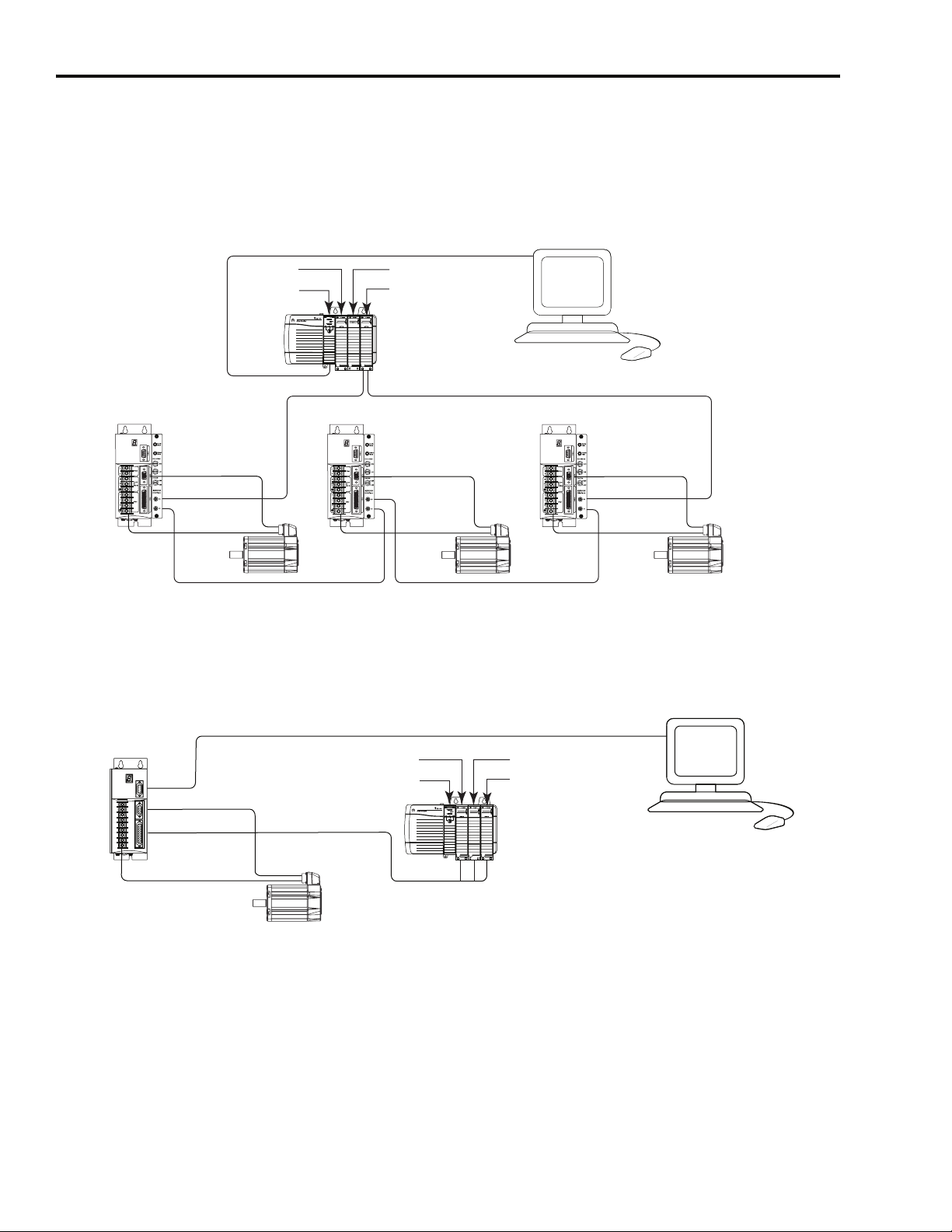
Ultra3000-SE (SERCOS) Digital Servo Drive System Overview
Ultra3000-SE
ControlLogix
Encoder Feedback
Motor Power
Input
Controller
Commissioning and Communications
Output
1756-MxxSE SERCOS
Interface Module
ControlLogix Chassis
SERCOS Fiber-Optic Ring
Ultra3000-SE
Encoder Feedback
Motor Power
MP-Series
Servo Motor
SERCOS Fiber-Optic Ring
RSLogix 5000
Ultra3000-SE
MP-Series
Servo Motor
Figure 1.2
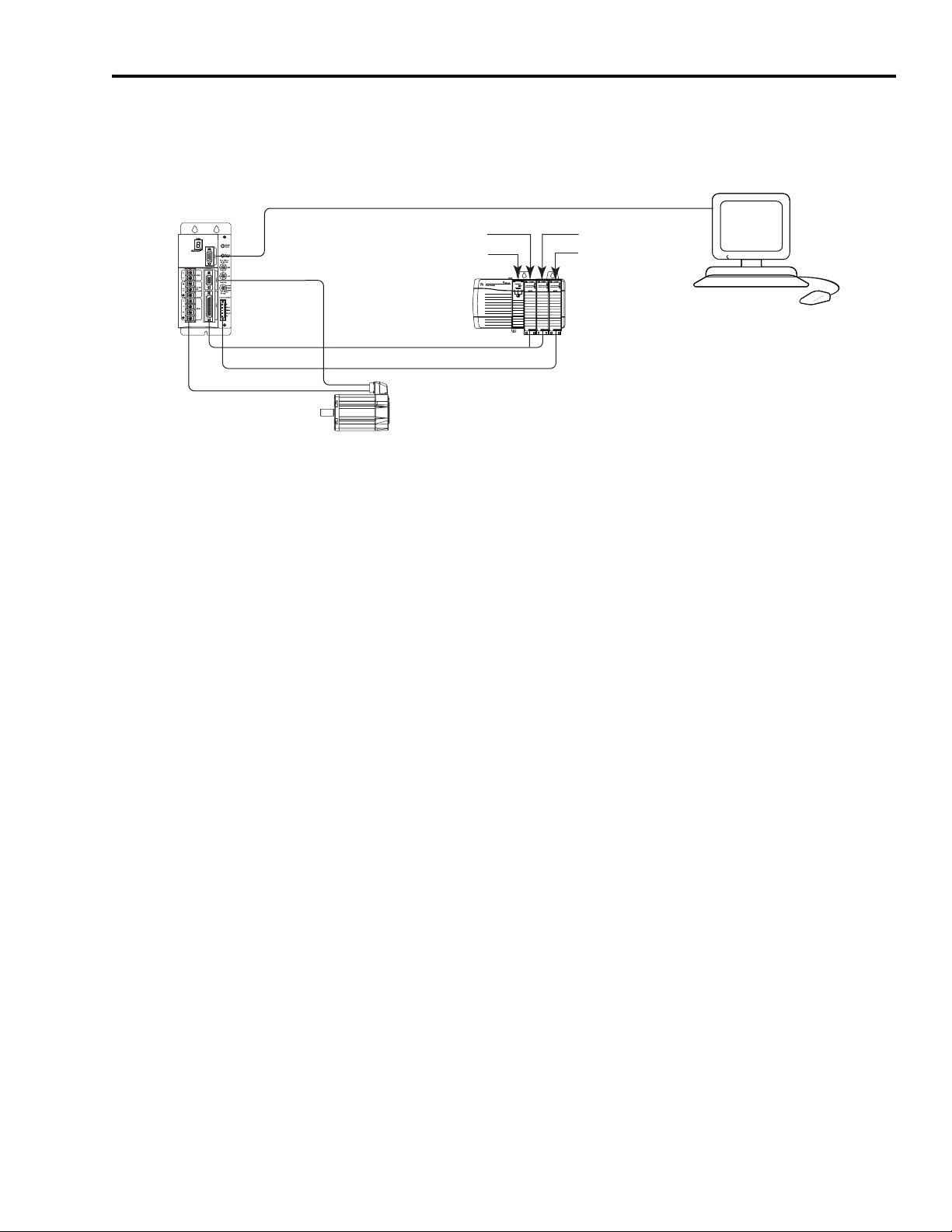
Ultra3000 Digital Servo Drive System Overview
Encoder Feedback
Motor Power
MP-Series
Servo Motor
Ultra3000
Encoder Feedback
Motor Power
Commissioning and Communications
Input
ControlLogix Controller
I/O and Commands
MP-Series
Servo Motor
PC-Powered Ultraware
Output
1756-M02AE Servo Module
ControlLogix Chassis
Publication 2098-IN003E-EN-P — April 2004
Page 29
Installing Your Ultra3000 1-5
Figure 1.3
Ultra3000-DN (DeviceNet) Digital Servo Drive System Overview
Ultra3000-DN
Encoder Feedback
Motor Power
Before Mounting Your System
Commissioning and Communications
ControlLogix Controller
I/O and Commands
DeviceNet Network
MP-Series
Servo Motor
Input
Output
DeviceNet Network Card
ControlLogix Chassis
PC-Powered Ultraware
Before you mount your Ultra3000 system make sure you understand
the following:
• how to unpack the system
• the minimum mounting requirements
Unpacking Modules
Each Ultra3000 ships with the following:
• One Ultra3000 drive
• One installation manual (publication 2098-IN003x-EN-P)
Remove all packing material, wedges, and braces from within and
around the components. After unpacking, check the item(s) name
plate catalog number against the purchase order.
Publication 2098-IN003E-EN-P — April 2004
Page 30
1-6 Installing Your Ultra3000
System Mounting Requirements
There are several things that you need to take into account when
preparing to mount the Ultra3000:
• The Ultra3000 must be enclosed in a grounded conductive
enclosure offering protection as defined in standard EN 60529
(IEC 529) to IP22 such that they are not accessible to an operator
or unskilled person, in order to comply with UL
requirements. A NEMA 4X enclosure exceeds these requirements
providing protection to IP66.
• The ambient temperature of the location in which you will install
the Ultra3000 must not exceed 55° C (131° F).
• You must install the Ultra3000 vertically on the panel (refer to
Figure 1.4 for mounting orientation).
• You must install the panel on a flat, rigid, vertical surface that
won’t be subjected to shock, vibration, moisture, oil mist, dust, or
corrosive vapors.
®
and CE
• You need to maintain minimum clearances (refer to Figure 1.4) for
proper airflow, easy module access, and proper cable bend radius.
• The Ultra3000 can operate at elevations to 1000 m (3280 ft)
without derating, however, the continuous current rating must be
de-rated by 3% for each additional 300 m (984 ft) up to 3000 m
(9842 ft). Consult your local Allen-Bradley representative prior to
operating above 3000 m (9842 ft).
ATTENTION
!
Refer to Appendix A for mounting dimensions, power dissipation, and
environmental specifications for the Ultra3000.
Plan the installation of your system so that you can
perform all cutting, drilling, tapping, and welding
with the system removed from the enclosure.
Because the system is of the open type construction,
be careful to keep any metal debris from falling into
it. Metal debris or other foreign matter can become
lodged in the circuitry, which can result in damage to
components.
Publication 2098-IN003E-EN-P — April 2004
Page 31

Ventilation Requirements
This section provides information to assist you in sizing your cabinet
and locating your Ultra3000 drive(s) inside the cabinet.
Figure 1.4
Minimum Clearance Requirements
Ultra3000 mounted
vertically on the panel
Installing Your Ultra3000 1-7
50.8 mm (2.0 in.) clearance
for airflow and installation
Do not mount drive on its side.
Allow 12.7 mm (0.5 in.)
side clearance
Allow 12.7 mm (0.5 in.)
side clearance
Minimum cabinet depth = 243.8 mm (9.6 in.)
Minimum front clearance = 76.2 mm (3.0 in.)
Motor cable entry area for ground clamp
50.8 mm (2.0 in.) clearance
for airflow and installation
IMPORTANT
If the cabinet is ventilated, use filtered or
conditioned air to prevent the accumulation of dust
and dirt on electronic components. The air should be
free of oil, corrosives, or electrically conductive
contaminates.
Refer to Appendix A for Ultra3000 power dissipation specifications.
Publication 2098-IN003E-EN-P — April 2004
Page 32

1-8 Installing Your Ultra3000
Sizing an Enclosure
As an additional aid in sizing an enclosure, with no active method of
heat dissipation, either of the following approximate equations can be
used:
Metric Standard English
0.38Q
A
------------------------= A
1.8T 1.1–
Where T is temperature difference between
inside air and outside ambient (°C), Q is heat
generated in enclosure (Watts), and A is
enclosure surface area (m
of all six sides of an enclosure is calculated as
A = 2dw + 2dh + 2wh A = (2dw + 2dh + 2wh) / 144
Where d (depth), w (width), and h (height) are in
meters.
2
). The exterior surface
Where T is temperature difference between
inside air and outside ambient (°F), Q is heat
generated in enclosure (Watts), and A is
enclosure surface area (ft²). The exterior surface
of all six sides of an enclosure is calculated as
Where d (depth), w (width), and h (height) are in
inches.
4.08Q
----------------=
T 1.1–
Transformer Sizing
The Ultra3000 does not require isolation transformers. However, a
transformer may be required to match the voltage requirements of the
controller to the available service. To size a transformer for the main
AC power inputs, the power output (KVA) of each axis must be
known. This can be derived by calculating the horsepower for each
axis and converting that horsepower into units of watts. If you are
supplying power to more than one motor and an Ultra3000, simply
add the kW ratings together from each calculation to get a system kW
total.
Publication 2098-IN003E-EN-P — April 2004
IMPORTANT
If using an autotransformer, ensure that the phase to
neutral/ground voltages do not exceed the input
voltage ratings of the drive.
Definitions:
kW = power or real power
KVA = apparent power
Transformer KVA rating = (Sum of average output power of each axis)
x 2.0.
Page 33

Installing Your Ultra3000 1-9
IMPORTANT
If you are using the Rockwell Automation/
Allen-Bradley system sizing program, the average
speed and average torque data has already been
calculated and can be used in the above equation. If
you are not sure of the exact speed and torque in
your application, another approach is to look at the
speed/torque curve for your Ultra3000/motor
combination and use the values for the worst case
continuous speed and torque.
IMPORTANT
Calculations are multiplied by a factor to compensate
for the power and loss elements within a power
system. A factor of 2.0 is used with a single phase
system and a factor of 1.5 is used with a three phase
system. This factor should minimize the effects of the
secondary line voltage sagging in the transformer
during peak current periods.
Example: sizing a transformer to the voltage requirements of an
2098-DSD-020 and MPL-A320P motor:
Intro
KVA
KVA
Speed RPM()xTorque lb in–()
-------------------------------------------------------------------------------------x
5 000 RP M(),()X17.7 lb in–()
--------------------------------------------------------------------------------=
63 025,
42 250,
746Watts
--------------------------- x
HP
KVA
------------------------------ x 2 . 0=
1000W atts
Transformer Size 2.1 KVA=
Intro
The speed/torque curve information for 230V motors is based upon
an Ultra3000 input voltage of 230V ac. For a 115V ac input voltage, the
maximum speed can be reduced up to one half.
Intro
Intro
Intro
Intro
Intro
Intro
Intro
Intro
Intro
Publication 2098-IN003E-EN-P — April 2004
Page 34

1-10 Installing Your Ultra3000
Fuse Sizing
In the United States, the National Electric Code (NEC) specifies that
fuses must be selected based on the motor full load amperage (FLA).
The typical fuse size should be 300% of the motor FLA for non-time
delay fuses (and time-delay class CC fuses) or 175% of motor FLA for
time delay fuses. If these ratings are not high enough for starting
currents, the NEC allows non-time delay fuses (and time-delay class
CC fuses) to be sized up to 400% of the motor FLA and time-delay
fuses to be sized up to 225% of the motor FLA.
In most cases, fuses selected to match the drive input current rating
will meet the NEC requirements and provide the full drive capabilities.
Dual element, time delay (slow acting) fuses should be used to avoid
nuisance trips during the inrush current of power initialization. Refer
to the section Ultra3000 Power Specifications in Appendix A for input
current and inrush current specifications.
The Ultra3000 utilizes solid state motor short circuit protection rated as
shown in the table below.
Drive Models: Input Power Type
2098-DSD-xxx-xx or xxxX-xx
Input Power
and
Auxiliary Input
2098-DSD-HVxxx-xx or
HVxxxX-xx
Power
HF Bonding Your System
Short Circuit Current Rating with No Fuse
Restrictions:
Suitable for use on a circuit capable of delivering
not more than 5000 rms symmetrical amperes,
240V maximum.
Suitable for use on a circuit capable of delivering
not more than 5000 rms symmetrical amperes,
480V maximum.
Short Circuit Current Rating with Fuse
Restrictions:
Suitable for use on a circuit capable of delivering
not more than 200,000 rms symmetrical
amperes, 240V maximum, when protected by
high interrupting capacity, current limiting fuses
meeting UL 198C (Class CC, G, J, L, R, T).
Suitable for use on a circuit capable of delivering
not more than 200,000 rms symmetrical
amperes, 480V maximum, when protected by
high interrupting capacity, current limiting fuses
meeting UL 198C (Class CC, G, J, L, R, T).
Wiring to the auxiliary power terminals (L1 AUX and L2/N AUX) of
2
the drive should be 2.5 mm
(14 AWG) minimum and fusing for the
auxiliary power should be selected to properly protect the wire. For
example, if 60° C (140° F) wire is used, the fuse should not exceed
8A. If 75° C (167° F) wire is used, the fuse should not exceed 13A.
Refer to Fuse Specifications in Appendix A for fuse examples.
Bonding is the practice of connecting metal chassis, assemblies,
frames, shields and enclosures to reduce the effects of electromagnetic
interference (EMI). For more information on the concept of
high-frequency (HF) bonding, the ground plane principle, and
electrical noise reduction, refer to the System Design for Control of
Electrical Noise Reference Manual (publication GMC-RM001x-EN-P).
Publication 2098-IN003E-EN-P — April 2004
Page 35

Installing Your Ultra3000 1-11
Bonding Modules
Unless specified, most paints are not conductive and they act as
insulators. To achieve a good bond between modules and the
subpanel, surfaces need to be paint-free or plated. Bonding metal
surfaces creates a low-impedance exit path for high-frequency energy.
IMPORTANT
To improve the bond between the drive and
subpanel, construct your subpanel out of zinc plated
(paint-free) steel.
Improper bonding blocks that direct exit path and allows
high-frequency energy to travel elsewhere in the cabinet. Excessive
high-frequency energy can effect the operation of other
microprocessor controlled equipment. The illustrations that follow
(refer to Figure 1.5) show details of recommended bonding practices
for painted panels, enclosures, and mounting brackets.
Figure 1.5
Recommended Bonding Practices
Stud-mounting the subpanel
to the enclosure back wall
Back wall of
enclosure
Subpanel Welded stud
Star washer
Nut
Use a wire brush to remove paint from
threads to maximize ground
connection.
Use plated panels or scrape paint on
front of panel.
Welded
stud
Mounting bracket or
Flat washer
Nut
Stud-mounting a ground bus
or chassis to the subpanel
ground bus
Flat washer
If the mounting bracket is coated with
a non-conductive material (anodized,
painted, etc.), scrape the material
Star washer
around the mounting hole.
Subpanel
Scrape paint
Bolt-mounting a ground bus or chassis to the back-panel
Ground bus or
mounting bracket
Flat washer
Nut
Nut
Star washer
Subpanel
Tapped hole
Scrape paint on both sides of
panel and use star washers.
Star washer
Flat washer
If the mounting bracket is coated with
a non-conductive material (anodized,
painted, etc.), scrape the material
around the mounting hole.
Bolt
Star washer
Publication 2098-IN003E-EN-P — April 2004
Page 36

1-12 Installing Your Ultra3000
Bonding Multiple Subpanels
Bonding multiple subpanels creates a common low impedance exit
path for the high frequency energy inside the cabinet. Subpanels that
are not bonded together may not share a common low impedance
path. This difference in impedance may affect networks and other
devices that span multiple panels. Refer to the figure below for
recommended bonding practices.
Figure 1.6
Multiple Subpanels and Cabinet
Recommended:
Bond the top and bottom of each subpanel to the cabinet using
25.4 mm (1.0 in.) by 6.35 mm (0.25 in.) wire braid.
Planning Your Panel Layout
Bonded cabinet
ground bus to
subpanel
Scrape the paint around each fastener to
maximize metal to metal contact.
This section outlines the practices which minimize the possibility of
noise-related failures as they apply specifically to Ultra3000
installations. For more information on the concept of electrical noise
reduction, refer to System Design for Control of Electrical Noise
(publication GMC-RM001x-EN-P).
Publication 2098-IN003E-EN-P — April 2004
Page 37

Installing Your Ultra3000 1-13
Establishing Noise Zones
Observe the following guidelines when laying out your panel (refer to
Figure 1.7 for zone locations).
• The clean zone (C) is above and beneath the Ultra3000 and
includes CN1, CN2, CN3, and the DC filter (grey wireways).
• The dirty zone (D) is left of the Ultra3000 (black wireways) and
includes the circuit breakers, transformer, AC line filter, contactors,
24V dc power supply, and motor power cables.
• The very dirty zone (VD) is limited to where the AC line (EMC)
filter AC output jumpers over to the Ultra3000. Shielded cable is
required only if the very dirty cables enter a wireway.
• The SERCOS fiber-optic cables are immune to electrical noise.
Figure 1.7
Establishing Noise Zones
Dirty Wireway Clean Wireway
(1)
Contactors
D
C
DC
Filter
Mount AC line
2
filter as close
to the drive as
possible
AC
Line Filter
Motor Power Cables
Route Encoder/Analog/Registration
VD
D
Shielded Cable
Ultra3000
CN3
CN2
C
CN1 I/O Cable
1
D
D
Circuit
Breaker
XFMR
Route Motor Power
Shielded Cable
1
If I/O cable contains (dirty) relay wires, route cable with motor power wires in dirty wireway.
2
This is a clean 24V dc available for CN1 I/O power supply. The 24V enters the clean wireway and exits to the right.
3
This is a dirty 24V dc available for motor brakes and contactors. The 24V enters the dirty wireway and exits to the
left.
D
24V
Power Supply
3
Very dirty EMC filter connections
segregated (not in wireway)
Publication 2098-IN003E-EN-P — April 2004
Page 38

1-14 Installing Your Ultra3000
Observe the following guidelines when installing your 1756-MxxSE
SERCOS interface module (refer to Figure 1.8 for zone locations).
• The clean zone (C) is beneath the less noisy modules (I/O, analog,
encoder, registration, etc. (grey wireway).
• The dirty zone (D) is above and below the power supply and
noisy modules (black wireway).
• The SERCOS fiber-optic cables are immune to electrical noise.
Figure 1.8
Establishing Noise Zones (ControlLogix)
Dirty Wireway
(1)
D
EMC
Filter
EMC filter/power supply
connections segregated
(not in wireway)
Route dirty wireways directly above the ControlLogix rack
(shielded by the chassis)
D
Dirty I/O
(24V dc I/O, AC I/O)
Spare Slot(s)
(Analog, Encoder
Registration, etc.)
C
Clean I/O
Clean Wireway
Cable Categories for the Ultra3000
The table below indicates the zoning requirements of cables
connecting to the Ultra3000.
Wire/Cable Connector
DC-/DC+
L1, L2, L3 (shielded cable) X X
L1, L2, L3 (unshielded cable) X
U, V, W (motor power) X X
Registration Wiring CN1 X X
Other 24V Wiring CN1 X
Motor Feedback CN2 X X
Serial Communications CN3 X X
Fiber-Optic Rx and Tx No Restrictions
Publication 2098-IN003E-EN-P — April 2004
TB1
Very
Dirty
Zone Method
Dirty Clean
X
Ferrite
Sleeve
Shielded
Cable
Page 39

Installing Your Ultra3000 1-15
The table below indicates the zoning requirements of cables
connecting to the External Shunt Resistor Kit.
Zone Method
Wire/Cable Connector
Shunt Connections (shielded option)
Shunt Connections (unshielded option) X
Fan (if present) N/A X
TB2
Very
Dirty
Dirty Clean
Mounting Guidelines to Reduce Electrical Noise
When mounting an AC line (EMC) filter or external shunt resistor refer
to the sections below for guidelines designed to reduce system
failures caused by excessive electrical noise.
Ferrite
Sleeve
XX
Shielded
Cable
ATTENTION
!
High voltage exists in AC line filters. The filter must
be grounded properly before applying power. Filter
capacitors retain high voltages after power removal.
Before handling the equipment, voltages should be
measured to determine safe levels. Failure to observe
this precaution could result in personal injury.
AC Line Filters
Observe the following guidelines when mounting your AC line (EMC)
filter (refer to Figure 1.7 for an example).
• Mount the AC line filter and bonded cabinet ground bus on the
same panel as the Ultra3000, and as close to the Ultra3000 as
possible.
• Good HF bonding to the panel is critical. For painted panels, refer
to Figure 1.5.
• Segregate input and output wiring as far as possible.
IMPORTANT
CE test certification applies only to AC line filter and
single drive. Multiple drive loads may perform
satisfactorily, but the user takes legal responsibility.
Publication 2098-IN003E-EN-P — April 2004
Page 40

1-16 Installing Your Ultra3000
External Shunt Resistor
Observe the following guidelines when mounting your external shunt
resistor (refer to Figure 1.9 and for an example).
• Mount circuit components and wiring in the very dirty zone or in
an external shielded enclosure. Run shunt power and fan wiring
inside metal conduit to minimize the effects of EMI and RFI.
• Mount resistors (other than metal-clad) in a shielded and
ventilated enclosure outside the cabinet.
• Keep unshielded wiring as short as possible. Keep shunt wiring as
flat to the cabinet as possible.
Figure 1.9
External Shunt Resistor Outside the Enclosure
Customer-supplied
metal enclosure
150 mm (6.0 in.) of
clearance on all sides
of the shunt module
minimum
Dirty Wireway
Very dirty shunt connections
segregated (not in wireway).
Maximum Length: 3.05 m (10 ft).
D
Circuit
Breaker
XFMR
24V
Power Supply
1394 Digital Servo Controller
300W Shunt Module
ALLEN-BRADLEY
R
BULLETIN 1394 300W SHUNT MODULE
CAT. PART SER.
INPUT DC INPUT AC
FOR FUSE REPLACEMENT USE:
BUSSMAN CAT. NO.
FOR USE WITH 1394-SJT22-X SYSTEM MODULE
Metal conduit
(where required by local code)
Shunt Wiring Methods:
Twisted pair in conduit (1st choice).
Shielded twisted pair (2nd choice).
Twisted pair, 2 twists per foot min. (3rd choice).
C
D
Contactors
DC
Filter
D
AC
Line Filter
VD
VD
Internal
External
Shunt
Motor
DC Bus
100-240 VAC
50/60 Hz
1
2
3
TB2
U
V
W
+
-
L1
L2/N
L1
AUX
L2/N
AUX
TB1
Clean Wireway
Ultra3000
Publication 2098-IN003E-EN-P — April 2004
D
Route Motor Power
Shielded Cable
Very dirty power connections
segregated (not in wireway)
Motor Power Cable
Route Encoder/Analog/Registration
Enclosure
D
Shielded Cables
C
Page 41

Installing Your Ultra3000 1-17
When mounting your shunt module inside the enclosure, follow these
additional guidelines (refer to Figure 1.10 and for an example).
• Metal-clad modules can be mounted anywhere in the dirty zone,
but as close to the Ultra3000 as possible.
• Shunt power wires can be run with motor power cables.
• Keep unshielded wiring as short as possible. Keep shunt wiring as
flat to the cabinet as possible.
• Separate shunt power cables from other sensitive, low voltage
signal cables.
Figure 1.10
External Shunt Resistor Inside the Enclosure
Dirty Wireway
Very dirty shunt connections
segregated (not in wireway).
Maximum Length: 3.05 m (10 ft).
Circuit
Breaker
XFMR
Power Supply
24V
150 mm (6.0 in.) of
clearance on all sides
of the shunt module
minimum
1394 Digital Servo Controller
300W Shunt Module
ALLEN-BRADLEY
R
BULLETIN 1394 300W SHUNT MODULE
CAT. PART SER.
INPUT DC INPUT AC
FOR FUSE REPLACEMENT USE:
BUSSMAN CAT. NO.
FOR USE WITH 1394-SJT22-X SYSTEM MODULE
Shunt Wiring Methods:
Twisted pair in conduit (1st choice).
Shielded twisted pair (2nd choice).
Twisted pair, 2 twists per foot min. (3rd choice).
C
D
Contactors
DC
Filter
D
AC
Line Filter
VD
VD
Internal
External
Shunt
Motor
DC Bus
100-240 VAC
50/60 Hz
1
2
3
TB2
U
V
W
+
-
L1
L2/N
L1
AUX
L2/N
AUX
TB1
Clean Wireway
Ultra3000
D
Route Motor Power
Shielded Cable
Very dirty power connections
segregated (not in wireway)
Motor Power Cable
Route Encoder/Analog/Registration
Enclosure
D
C
Shielded Cables
Publication 2098-IN003E-EN-P — April 2004
Page 42

1-18 Installing Your Ultra3000
Mounting Your Ultra3000 Drive
The procedures in this section assume you have prepared your panel
and understand how to bond your system. For installation instructions
regarding other equipment and accessories, refer to the instructions
that came with each of the accessories for their specific requirements.
ATTENTION
!
To mount your Ultra3000 drive:
1. Layout the position for the Ultra3000 and accessories in the
enclosure (refer to Establishing Noise Zones for panel layout
recommendations). Mounting hole dimensions for the Ultra3000
are shown in Appendix A.
This drive contains ESD (Electrostatic Discharge)
sensitive parts and assemblies. You are required to
follow static control precautions when you install,
test, service, or repair this assembly. If you do not
follow ESD control procedures, components can be
damaged. If you are not familiar with static control
procedures, refer to Allen-Bradley publication
8000-4.5.2, Guarding Against Electrostatic Damage
or any other applicable ESD Protection Handbook.
2. Attach the Ultra3000 to the cabinet, first using the upper mounting
slots of the drive and then the lower. The recommended mounting
hardware is M5 metric (1/4-20) or #10 MS bolts. Observe bonding
techniques as described in HF Bonding Your System.
IMPORTANT
3. Tighten all mounting fasteners.
To improve the bond between the Ultra3000 and
subpanel, construct your subpanel out of zinc
plated (paint-free) steel.
Publication 2098-IN003E-EN-P — April 2004
Page 43

Ultra3000 Connector Data
Chapter
2
Chapter Objectives
Understanding Ultra3000 Connectors
Designator Description Connector
CN1 User Input/Output 44-pin high-density D-shell
CN2 Motor Feedback 15-pin high-density D-shell
CN3 Serial Port 9-pin standard D-shell
TB
TB1
TB2 Shunt
This chapter provides I/O, encoder, and serial interface connector
locations and signal descriptions for your Ultra3000. This chapter
includes:
• Understanding Ultra3000 Connectors
• Understanding Ultra3000 I/O Specifications
• Understanding Motor Encoder Feedback Specifications
• Understanding Auxiliary Encoder Feedback Specifications
• Understanding the Serial Interface
Switch and LED locations are shown, however for switch and LED
configuration, refer to the Ultra3000 Digital Servo Drives Integration
Manual (publication 2098-IN005x-EN-P).
The following table provides a brief description of the Ultra3000 front
panel connectors and describes the connector type.
DC bus, Motor and
AC power
DC bus, Motor, AC
power, and auxiliary
AC power
9-position screw style barrier terminal strip
(2098-DSD-005x-xx, -010x-xx, and -020x-xx)
11- or 12-position screw style barrier terminal strip
(2098-DSD-030x-xx, -075x-xx, -150x-xx, HVxxx-xx, and HVxxxX-xx)
3-position screw style barrier terminal strip
(2098-DSD-030x-xx, -075x-xx, -150x-xx, HVxxx-xx, and HVxxxX-xx)
All signal connections on the Ultra3000 use commonly available
D-shell type connectors.
For connector pin-outs and the location of connectors,
switches, and status LEDs on:
2098-DSD-xxx and -HVxxx Ultra3000 drives Figures 2.1-2.4 and the tables that follow on pages 2-2 through 2-9.
2098-DSD-xxx and -HVxxx Ultra3000 drives with SERCOS interface Figures 2.5-2.8 and the tables that follow on pages 2-10 through 2-17.
2098-DSD-xxx and -HVxxx Ultra3000 drives with DeviceNet interface Figures 2.9-2.12 and the tables that follow on pages 2-18 through 2-25.
1 Publication 2098-IN003E-EN-P — April 2004
Refer to:
Page 44

2-2 Ultra3000 Connector Data
Ultra3000 Front Panel Connections
Use the figure below to locate the front panel connections on the
Ultra3000 230V drives (500W, 1 kW, and 2 kW).
Figure 2.1
Ultra3000 Front Panel Connections
for 2098-DSD-005, -005X, -010, -010X, -020, and -020X
9-pin CN3
Serial Connector
Seven Segment
Status LED
DC Bus Connections for
Active Shunt Resistor Kit
AC Input Power
Connections
Motor Power
Connections
Motor Power
Cable Shield Clamp
Logic Power LED
CN3 9-pin
Serial Port
Connector
CN2 15-pin
Motor Feedback
Connector
CN1 44-pin
User I/O
Connector
Pin 9
Pin 6
15-pin CN2
Feedback Connector
Pin 15
Pin 11
Pin 6
44-pin CN1
I/O Connector
Pin 44
Pin 31
Pin 16
Pin 5
Pin 1
Pin 10
Pin 5
Pin 1
Pin 30
Pin 15
Pin 1
Serial Port Connector
The following table provides the signal descriptions and pin-outs for
the CN3 serial port (9-pin) connector.
Publication 2098-IN003E-EN-P — April 2004
CN3 Pin Description Signal
1 RS-422/RS-485 Input+ RCV+
2 RS-232 Input RCV
3 RS-232 Output XMT
4 RS-422/RS-485 Output+ XMT+
5 Common COM
6Reserved –
7 RS-422/RS-485 Input- RCV-
8 RS-422/RS-485 Output- XMT-
9 Reserved –
Page 45

Ultra3000 Connector Data 2-3
I/O Connector
The following table provides the signal descriptions and pin-outs for
the CN1 I/O (44-pin) connector.
CN1 Pin Description Signal CN1 Pin Description Signal
1 Auxiliary Encoder Power Out (+5V) EPWR 23 Programmable Analog Output AOUT
2 Common ECOM 24 Analog Current Limit Input ILIMIT
3 Auxiliary Logic Power In (+5V) AUXPWR 25 Command + COMMAND+
4 Auxiliary A+/Step+/CW+ AX+ 26 Command - COMMAND-
5 Auxiliary A-/Step-/CW- AX- 27 I/O Common IOCOM
6 Auxiliary B+/Dir+/CCW+ BX+ 28 I/O Common IOCOM
7 Auxiliary B-/Dir-/CCW- BX- 29 I/O Power IOPWR
8 Auxiliary Encoder Ch I+ IX+ 30 I/O Power IOPWR
9 Auxiliary Encoder Ch I- IX- 31 Digital Input 1 INPUT1
10 Unbuffered Motor Encoder Ch A+ AM+ 32 Digital Input 2 INPUT2
11 Unbuffered Motor Encoder Ch A- AM- 33 Digital Input 3 INPUT3
12 Unbuffered Motor Encoder Ch B+ BM+ 34 Digital Input 4 INPUT4
13 Unbuffered Motor Encoder Ch B- BM- 35 Digital Input 5 INPUT5
14 Unbuffered Motor Encoder Ch I+ IM+ 36 Digital Input 6 INPUT6
15 Unbuffered Motor Encoder Ch I- IM- 37 Digital Input 7 INPUT7
16 Buffered Motor Encoder Ch A+ AMOUT+ 38 Digital Input 8 INPUT8
17 Buffered Motor Encoder Ch A- AMOUT- 39 Digital Output 1 OUTPUT1
18 Buffered Motor Encoder Ch B+ BMOUT+ 40 Digital Output 2 OUTPUT2
19 Buffered Motor Encoder Ch B- BMOUT- 41 Digital Output 3 OUTPUT3
20 Buffered Motor Encoder Ch I+ IMOUT+ 42 Digital Output 4 OUTPUT4
21 Buffered Motor Encoder Ch I- IMOUT- 43 Normally Open Relay Output+ RELAY+
22 Common ACOM 44 Normally Open Relay Output- RELAY-
Motor Encoder Connector
The following table provides the signal descriptions and pin-outs for
the CN2 motor encoder (15-pin) connector.
CN2 Pin Description Signal CN2 Pin Description Signal
1 Channel A+/Sine Differential Input+ AM+ 9 Positive Overtravel Limit +LIMIT
2 Channel A-/Sine Differential Input- AM- 10 Channel I-/Index Pulse- IM-
3 Channel B+/Cosine Differential Input+ BM+ 11 Thermostat TS
4 Channel B-/Cosine Differential Input- BM- 12 Commutation Channel S1 S1
5 Channel I+/Index Pulse+ IM+ 13 Commutation Channel S2 S2
6 Common ECOM 14 Encoder Power (+5V) EPWR_5V
7 Reserved – 15 Negative Overtravel Limit -LIMIT
8 Commutation Channel S3 S3
Publication 2098-IN003E-EN-P — April 2004
Page 46

2-4 Ultra3000 Connector Data
Use the figure below to locate the front panel connections on the
Ultra3000 230V drives (3 kW).
Figure 2.2
Ultra3000 Front Panel Connections for 2098-DSD-030 and -030X
Passive Shunt
Resistor Connections
Motor Power
Connections
AC Input Power
Connections
Motor Power
Cable Shield Clamp
External
Shunt
100-240 VAC
50/60 Hz
Internal
DC Bus
Seven Segment
1
2
3
TB2
Status LED
Logic Power LED
9-pin CN3
Serial Connector
Pin 9
Pin 6
Pin 5
Pin 1
15-pin CN2
Feedback Connector
CN3 9-pin
Serial Port
U
V
Motor
W
Connector
CN2 15-pin
Motor Feedback
Connector
+
-
L1
L2/N
L1
AUX
L2/N
AUX
TB1
CN1 44-pin
User I/O
Connector
Pin 15
Pin 11
Pin 6
44-pin CN1
I/O Connector
Pin 44
Pin 31
Pin 10
Pin 5
Pin 1
Pin 30
Pin 15
Pin 1
Pin 16
Publication 2098-IN003E-EN-P — April 2004
Serial Port Connector
The following table provides the signal descriptions and pin-outs for
the CN3 serial port (9-pin) connector.
CN3 Pin Description Signal
1 RS-422/RS-485 Input+ RCV+
2 RS-232 Input RCV
3 RS-232 Output XMT
4 RS-422/RS-485 Output+ XMT+
5 Common COM
6Reserved –
7 RS-422/RS-485 Input- RCV-
8 RS-422/RS-485 Output- XMT-
9 Reserved –
Page 47

Ultra3000 Connector Data 2-5
I/O Connector
The following table provides the signal descriptions and pin-outs for
the CN1 I/O (44-pin) connector.
CN1 Pin Description Signal CN1 Pin Description Signal
1 Auxiliary Encoder Power Out (+5V) EPWR 23 Programmable Analog Output AOUT
2 Common ECOM 24 Analog Current Limit Input ILIMIT
3 Reserved – 25 Command + COMMAND+
4 Auxiliary A+/Step+/CW+ AX+ 26 Command - COMMAND-
5 Auxiliary A-/Step-/CW- AX- 27 I/O Common IOCOM
6 Auxiliary B+/Dir+/CCW+ BX+ 28 I/O Common IOCOM
7 Auxiliary B-/Dir-/CCW- BX- 29 I/O Power IOPWR
8 Auxiliary Encoder Ch I+ IX+ 30 I/O Power IOPWR
9 Auxiliary Encoder Ch I- IX- 31 Digital Input 1 INPUT1
10 Unbuffered Motor Encoder Ch A+ AM+ 32 Digital Input 2 INPUT2
11 Unbuffered Motor Encoder Ch A- AM- 33 Digital Input 3 INPUT3
12 Unbuffered Motor Encoder Ch B+ BM+ 34 Digital Input 4 INPUT4
13 Unbuffered Motor Encoder Ch B- BM- 35 Digital Input 5 INPUT5
14 Unbuffered Motor Encoder Ch I+ IM+ 36 Digital Input 6 INPUT6
15 Unbuffered Motor Encoder Ch I- IM- 37 Digital Input 7 INPUT7
16 Buffered Motor Encoder Ch A+ AMOUT+ 38 Digital Input 8 INPUT8
17 Buffered Motor Encoder Ch A- AMOUT- 39 Digital Output 1 OUTPUT1
18 Buffered Motor Encoder Ch B+ BMOUT+ 40 Digital Output 2 OUTPUT2
19 Buffered Motor Encoder Ch B- BMOUT- 41 Digital Output 3 OUTPUT3
20 Buffered Motor Encoder Ch I+ IMOUT+ 42 Digital Output 4 OUTPUT4
21 Buffered Motor Encoder Ch I- IMOUT- 43 Normally Open Relay Output+ RELAY+
22 Common ACOM 44 Normally Open Relay Output- RELAY-
Motor Encoder Connector
The following table provides the signal descriptions and pin-outs for
the CN2 motor encoder (15-pin) connector.
CN2 Pin Description Signal CN2 Pin Description Signal
1 Channel A+/Sine Differential Input+ AM+ 9 Positive Overtravel Limit +LIMIT
2 Channel A-/Sine Differential Input- AM- 10 Channel I-/Index Pulse- IM-
3 Channel B+/Cosine Differential Input+ BM+ 11 Thermostat TS
4 Channel B-/Cosine Differential Input- BM- 12 Commutation Channel S1 S1
5 Channel I+/Index Pulse+ IM+ 13 Commutation Channel S2 S2
6 Common ECOM 14 Encoder Power (+5V) EPWR_5V
7 Encoder Power (+9V) EPWR_9V 15 Negative Overtravel Limit -LIMIT
8 Commutation Channel S3 S3
Publication 2098-IN003E-EN-P — April 2004
Page 48

2-6 Ultra3000 Connector Data
Passive Shunt
Resistor Connections
Use the figure below to locate the front panel connections on the
Ultra3000 230V (7.5 and 15 kW).
Figure 2.3
Ultra3000 Front Panel Connections for 2098-DSD-075, -075X, -150, and -150X
9-pin CN3
Serial Connector
Pin 9
Pin 6
15-pin CN2
Feedback Connector
External
Shunt
Internal
Seven Segment
1
2
3
TB2
Status LED
Logic Power LED
Pin 5
Pin 1
Motor Power
Connections
AC Input Power
Connections
Motor Power
Cable Shield Clamp
Pin 10
Pin 5
Pin 1
Pin 30
Pin 15
Pin 1
DC Bus
100-240 VAC
50/60 Hz
CN3 9-pin
U
V
Motor
W
+
-
L1
L2
L3
L1
AUX
L2/N
AUX
TB1
Serial Port
Connector
CN2 15-pin
Motor Feedback
Connector
CN1 44-pin
User I/O
Connector
Pin 15
Pin 11
Pin 6
44-pin CN1
I/O Connector
Pin 44
Pin 31
Pin 16
Serial Port Connector
The following table provides the signal descriptions and pin-outs for
the CN3 serial port (9-pin) connector.
CN3 Pin Description Signal
1 RS-422/RS-485 Input+ RCV+
2 RS-232 Input RCV
3 RS-232 Output XMT
4 RS-422/RS-485 Output+ XMT+
5 Common COM
6Reserved –
7 RS-422/RS-485 Input- RCV-
8 RS-422/RS-485 Output- XMT-
9 Reserved –
Publication 2098-IN003E-EN-P — April 2004
Page 49

Ultra3000 Connector Data 2-7
I/O Connector
The following table provides the signal descriptions and pin-outs for
the CN1 I/O (44-pin) connector.
CN1 Pin Description Signal CN1 Pin Description Signal
1 Auxiliary Encoder Power Out (+5V) EPWR 23 Programmable Analog Output AOUT
2 Common ECOM 24 Analog Current Limit Input ILIMIT
3 Reserved – 25 Command + COMMAND+
4 Auxiliary A+/Step+/CW+ AX+ 26 Command - COMMAND-
5 Auxiliary A-/Step-/CW- AX- 27 I/O Common IOCOM
6 Auxiliary B+/Dir+/CCW+ BX+ 28 I/O Common IOCOM
7 Auxiliary B-/Dir-/CCW- BX- 29 I/O Power IOPWR
8 Auxiliary Encoder Ch I+ IX+ 30 I/O Power IOPWR
9 Auxiliary Encoder Ch I- IX- 31 Digital Input 1 INPUT1
10 Unbuffered Motor Encoder Ch A+ AM+ 32 Digital Input 2 INPUT2
11 Unbuffered Motor Encoder Ch A- AM- 33 Digital Input 3 INPUT3
12 Unbuffered Motor Encoder Ch B+ BM+ 34 Digital Input 4 INPUT4
13 Unbuffered Motor Encoder Ch B- BM- 35 Digital Input 5 INPUT5
14 Unbuffered Motor Encoder Ch I+ IM+ 36 Digital Input 6 INPUT6
15 Unbuffered Motor Encoder Ch I- IM- 37 Digital Input 7 INPUT7
16 Buffered Motor Encoder Ch A+ AMOUT+ 38 Digital Input 8 INPUT8
17 Buffered Motor Encoder Ch A- AMOUT- 39 Digital Output 1 OUTPUT1
18 Buffered Motor Encoder Ch B+ BMOUT+ 40 Digital Output 2 OUTPUT2
19 Buffered Motor Encoder Ch B- BMOUT- 41 Digital Output 3 OUTPUT3
20 Buffered Motor Encoder Ch I+ IMOUT+ 42 Digital Output 4 OUTPUT4
21 Buffered Motor Encoder Ch I- IMOUT- 43 Normally Open Relay Output+ RELAY+
22 Common ACOM 44 Normally Open Relay Output- RELAY-
Motor Encoder Connector
The following table provides the signal descriptions and pin-outs for
the CN2 motor encoder (15-pin) connector.
CN2 Pin Description Signal CN2 Pin Description Signal
1 Channel A+/Sine Differential Input+ AM+ 9 Positive Overtravel Limit +LIMIT
2 Channel A-/Sine Differential Input- AM- 10 Channel I-/Index Pulse- IM-
3 Channel B+/Cosine Differential Input+ BM+ 11 Thermostat TS
4 Channel B-/Cosine Differential Input- BM- 12 Commutation Channel S1 S1
5 Channel I+/Index Pulse+ IM+ 13 Commutation Channel S2 S2
6 Common ECOM 14 Encoder Power (+5V) EPWR_5V
7 Encoder Power (+9V) EPWR_9V 15 Negative Overtravel Limit -LIMIT
8 Commutation Channel S3 S3
Publication 2098-IN003E-EN-P — April 2004
Page 50

2-8 Ultra3000 Connector Data
Use the figure below to locate the front panel connections on the
Ultra3000 460V drives (3W, 5 kW, 10 kW, 15 kW, and 22 kW).
Figure 2.4
Ultra3000 Front Panel Connections for 2098-DSD-HVxxx and HVxxxX
Seven Segment
Status LED
Logic Power LED
9-pin CN3
Serial Connector
Passive Shunt
Resistor Connections
Motor Power
Connections
AC Input Power
Connections
Motor Power
Cable Shield Clamp
TB2
REGNAD REGNAD
Hazardous voltage
exists after power down.
50/60 Hz
TB1
1
2
3
+
-
W
V
U
L3
L2
L1
L1
AUX
L2
AUX
Internal
External Shunt
DC Bus
Motor
230-480 VAC
Serial Port Connector
CN3 9-pin
Serial Port
Connector
CN2 15-pin
Motor Feedback
Connector
CN1 44-pin
User I/O
Connector
Pin 9
Pin 6
15-pin CN2
Feedback Connector
Pin 15
Pin 11
Pin 6
44-pin CN1
I/O Connector
Pin 44
Pin 31
Pin 16
Pin 5
Pin 1
Pin 10
Pin 5
Pin 1
Pin 30
Pin 15
Pin 1
Publication 2098-IN003E-EN-P — April 2004
The following table provides the signal descriptions and pin-outs for
the CN3 serial port (9-pin) connector.
CN3 Pin Description Signal
1 RS-422/RS-485 Input+ RCV+
2 RS-232 Input RCV
3 RS-232 Output XMT
4 RS-422/RS-485 Output+ XMT+
5 Common COM
6 Reserved –
7 RS-422/RS-485 Input- RCV-
8 RS-422/RS-485 Output- XMT-
9 Reserved –
Page 51

Ultra3000 Connector Data 2-9
I/O Connector
The following table provides the signal descriptions and pin-outs for
the CN1 I/O (44-pin) connector.
CN1 Pin Description Signal CN1 Pin Description Signal
1 Auxiliary Encoder Power Out (+5V) EPWR 23 Programmable Analog Output AOUT
2 Common ECOM 24 Analog Current Limit Input ILIMIT
3 Reserved – 25 Command + COMMAND+
4 Auxiliary A+/Step+/CW+ AX+ 26 Command - COMMAND-
5 Auxiliary A-/Step-/CW- AX- 27 I/O Common IOCOM
6 Auxiliary B+/Dir+/CCW+ BX+ 28 I/O Common IOCOM
7 Auxiliary B-/Dir-/CCW- BX- 29 I/O Power IOPWR
8 Auxiliary Encoder Ch I+ IX+ 30 I/O Power IOPWR
9 Auxiliary Encoder Ch I- IX- 31 Digital Input 1 INPUT1
10 Unbuffered Motor Encoder Ch A+ AM+ 32 Digital Input 2 INPUT2
11 Unbuffered Motor Encoder Ch A- AM- 33 Digital Input 3 INPUT3
12 Unbuffered Motor Encoder Ch B+ BM+ 34 Digital Input 4 INPUT4
13 Unbuffered Motor Encoder Ch B- BM- 35 Digital Input 5 INPUT5
14 Unbuffered Motor Encoder Ch I+ IM+ 36 Digital Input 6 INPUT6
15 Unbuffered Motor Encoder Ch I- IM- 37 Digital Input 7 INPUT7
16 Buffered Motor Encoder Ch A+ AMOUT+ 38 Digital Input 8 INPUT8
17 Buffered Motor Encoder Ch A- AMOUT- 39 Digital Output 1 OUTPUT1
18 Buffered Motor Encoder Ch B+ BMOUT+ 40 Digital Output 2 OUTPUT2
19 Buffered Motor Encoder Ch B- BMOUT- 41 Digital Output 3 OUTPUT3
20 Buffered Motor Encoder Ch I+ IMOUT+ 42 Digital Output 4 OUTPUT4
21 Buffered Motor Encoder Ch I- IMOUT- 43 Normally Open Relay Output+ RELAY+
22 Common ACOM 44 Normally Open Relay Output- RELAY-
Motor Encoder Connector
The following table provides the signal descriptions and pin-outs for
the CN2 motor encoder (15-pin) connector.
CN2 Pin Description Signal CN2 Pin Description Signal
1 Channel A+/Sine Differential Input+ AM+ 9 Positive Overtravel Limit +LIMIT
2 Channel A-/Sine Differential Input- AM- 10 Channel I-/Index Pulse- IM-
3 Channel B+/Cosine Differential Input+ BM+ 11 Thermostat TS
4 Channel B-/Cosine Differential Input- BM- 12 Commutation Channel S1 S1
5 Channel I+/Index Pulse+ IM+ 13 Commutation Channel S2 S2
6 Common ECOM 14 Encoder Power (+5V) EPWR_5V
7 Encoder Power (+9V) EPWR_9V 15 Negative Overtravel Limit -LIMIT
8 Commutation Channel S3 S3
Publication 2098-IN003E-EN-P — April 2004
Page 52

2-10 Ultra3000 Connector Data
Seven Segment
Status LED
Logic Power LED
DC Bus Connections for
Active Shunt Resistor Kit
AC Input Power
Connections
Motor Power
Connections
Ultra3000 (with SERCOS) Front Panel Connections
Use the figure below to locate the front panel connections on the
Ultra3000 with SERCOS interface 230V drives (500W, 1 kW, and 2 kW).
Figure 2.5
Ultra3000 Front Panel Connections for 2098-DSD-005-SE, -010-SE, and -020-SE
9-pin CN3
Serial Connector
Module
Status LED
Network
Status LED
CN3 9-pin
Serial Port
Connector
Node Address
Switches
CN2 15-pin
Motor Feedback
Data Rate
8
Switch
SERCOS Interface
Receive (Rx) and
Transmit (Tx)
Connectors
Connector
Pin 9
Pin 6
15-pin CN2
Feedback Connector
Pin 15
Pin 11
Pin 6
44-pin CN1
I/O Connector
Pin 44
Pin 5
Pin 1
Pin 10
Pin 5
Pin 1
Pin 30
Pin 15
Motor Power
Cable Shield Clamp
CN1 44-pin
User I/O
Connector
Pin 31
Pin 16
Pin 1
Serial Port Connector
The following table provides the signal descriptions and pin-outs for
the CN3 serial port (9-pin) connector.
CN3 Pin Description Signal
1 RS-422/RS-485 Input+ RCV+
2 RS-232 Input RCV
3 RS-232 Output XMT
4 RS-422/RS-485 Output+ XMT+
5 Common COM
6Reserved –
7 RS-422/RS-485 Input- RCV-
8 RS-422/RS-485 Output- XMT-
9 Reserved –
Publication 2098-IN003E-EN-P — April 2004
Page 53

Ultra3000 Connector Data 2-11
I/O Connector
The following table provides the signal descriptions and pin-outs for
the CN1 I/O (44-pin) connector.
CN1 Pin Description Signal CN1 Pin Description Signal
1 Auxiliary Encoder Power Out (+5V) EPWR 23 Reserved –
2 Common ECOM 24 Analog Current Limit Input ILIMIT
3 Auxiliary Logic Power In (+5V) AUXPWR 25 Reserved –
4 Auxiliary Encoder Ch A+ AX+ 26 Reserved –
5 Auxiliary Encoder Ch A- AX- 27 I/O Common IOCOM
6 Auxiliary Encoder Ch B+ BX+ 28 I/O Common IOCOM
7 Auxiliary Encoder Ch B- BX- 29 I/O Power IOPWR
8 Auxiliary Encoder Ch I+ IX+ 30 I/O Power IOPWR
9 Auxiliary Encoder Ch I- IX- 31 Drive Enable Input ENABLE
10 Unbuffered Motor Encoder Ch A+ AM+ 32 Home Sensor Input HOME
11 Unbuffered Motor Encoder Ch A- AM- 33 Registration Sensor 1 Input REG1
12 Unbuffered Motor Encoder Ch B+ BM+ 34 Registration Sensor 2 Input REG2
13 Unbuffered Motor Encoder Ch B- BM- 35 Reserved –
14 Unbuffered Motor Encoder Ch I+ IM+ 36 Reserved –
15 Unbuffered Motor Encoder Ch I- IM- 37 Positive Overtravel Input OT_POS
16 Buffered Motor Encoder Ch A+ AMOUT+ 38 Negative Overtravel Input OT_NEG
17 Buffered Motor Encoder Ch A- AMOUT- 39 Drive Ready READY
18 Buffered Motor Encoder Ch B+ BMOUT+ 40 Reserved –
19 Buffered Motor Encoder Ch B- BMOUT- 41 Reserved –
20 Buffered Motor Encoder Ch I+ IMOUT+ 42 Reserved –
21 Buffered Motor Encoder Ch I- IMOUT- 43 Brake Relay Output+ BRAKE+
22 Common ACOM 44 Brake Relay Output- BRAKE-
1
READY signal only available with firmware version 1.29 (or above). Requires use of drive-mounted breakout board
(2090-U3CBB-DM44).
1
Motor Encoder Connector
The following table provides the signal descriptions and pin-outs for
the CN2 motor encoder (15-pin) connector.
CN2 Pin Description Signal CN2 Pin Description Signal
1 Channel A+/Sine Differential Input+ AM+ 9 Positive Overtravel Limit +LIMIT
2 Channel A-/Sine Differential Input- AM- 10 Channel I-/Index Pulse- IM-
3 Channel B+/Cosine Differential Input+ BM+ 11 Thermostat TS
4 Channel B-/Cosine Differential Input- BM- 12 Commutation Channel S1 S1
5 Channel I+/Index Pulse+ IM+ 13 Commutation Channel S2 S2
6 Common ECOM 14 Encoder Power (+5V) EPWR_5V
7 Reserved – 15 Negative Overtravel Limit -LIMIT
8 Commutation Channel S3 S3
Publication 2098-IN003E-EN-P — April 2004
Page 54

2-12 Ultra3000 Connector Data
Use the figure below to locate the front panel connections on the
Ultra3000 with SERCOS interface 230V drive (3 kW).
Figure 2.6
Ultra3000 Front Panel Connections for 2098-DSD-030-SE
Passive Shunt
Resistor Connections
Motor Power
Connections
AC Input Power
Connections
Motor Power
Cable Shield Clamp
External
Shunt
100-240 VAC
50/60 Hz
Internal
DC Bus
Seven Segment
1
2
3
TB2
Status LED
Logic Power LED
Module Status LED
Network Status LED
9-pin CN3
Serial Connector
Pin 9
Pin 6
Pin 5
Pin 1
Node Address Switches
15-pin CN2
8
Data Rate Switch
CN3 9-pin
Serial Port
U
Motor
V
W
Connector
CN2 15-pin
Motor Feedback
Connector
+
-
L1
L2/N
L1
AUX
L2/N
AUX
TB1
CN1 44-pin
User I/O
Connector
SERCOS interface
Receive (Rx) and
Transmit (Tx)
Connectors
Feedback Connector
Pin 15
Pin 11
Pin 6
44-pin CN1
I/O Connector
Pin 44
Pin 31
Pin 16
Pin 10
Pin 5
Pin 1
Pin 30
Pin 15
Pin 1
Publication 2098-IN003E-EN-P — April 2004
Serial Port Connector
The following table provides the signal descriptions and pin-outs for
the CN3 serial port (9-pin) connector.
CN3 Pin Description Signal
1 RS-422/RS-485 Input+ RCV+
2 RS-232 Input RCV
3 RS-232 Output XMT
4 RS-422/RS-485 Output+ XMT+
5 Common COM
6Reserved –
7 RS-422/RS-485 Input- RCV-
8 RS-422/RS-485 Output- XMT-
9 Reserved –
Page 55

Ultra3000 Connector Data 2-13
I/O Connector
The following table provides the signal descriptions and pin-outs for
the CN1 I/O (44-pin) connector.
CN1 Pin Description Signal CN1 Pin Description Signal
1 Auxiliary Encoder Power Out (+5V) EPWR 23 Reserved –
2 Common ECOM 24 Analog Current Limit Input ILIMIT
3 Reserved – 25 Reserved –
4 Auxiliary Encoder Ch A+ AX+ 26 Reserved –
5 Auxiliary Encoder Ch A- AX- 27 I/O Common IOCOM
6 Auxiliary Encoder Ch B+ BX+ 28 I/O Common IOCOM
7 Auxiliary Encoder Ch B- BX- 29 I/O Power IOPWR
8 Auxiliary Encoder Ch I+ IX+ 30 I/O Power IOPWR
9 Auxiliary Encoder Ch I- IX- 31 Drive Enable Input ENABLE
10 Unbuffered Motor Encoder Ch A+ AM+ 32 Home Sensor Input HOME
11 Unbuffered Motor Encoder Ch A- AM- 33 Registration Sensor 1 Input REG1
12 Unbuffered Motor Encoder Ch B+ BM+ 34 Registration Sensor 2 Input REG2
13 Unbuffered Motor Encoder Ch B- BM- 35 Reserved –
14 Unbuffered Motor Encoder Ch I+ IM+ 36 Reserved –
15 Unbuffered Motor Encoder Ch I- IM- 37 Positive Overtravel Input OT_POS
16 Buffered Motor Encoder Ch A+ AMOUT+ 38 Negative Overtravel Input OT_NEG
17 Buffered Motor Encoder Ch A- AMOUT- 39 Drive Ready READY
18 Buffered Motor Encoder Ch B+ BMOUT+ 40 Reserved –
19 Buffered Motor Encoder Ch B- BMOUT- 41 Reserved –
20 Buffered Motor Encoder Ch I+ IMOUT+ 42 Reserved –
21 Buffered Motor Encoder Ch I- IMOUT- 43 Brake Relay Output+ BRAKE+
22 Common ACOM 44 Brake Relay Output- BRAKE-
1
READY signal only available with firmware version 1.29 (or above). Requires use of drive-mounted breakout board
(2090-U3BB2-DM44).
1
Motor Encoder Connector
The following table provides the signal descriptions and pin-outs for
the CN2 motor encoder (15-pin) connector.
CN2 Pin Description Signal CN2 Pin Description Signal
1 Channel A+/Sine Differential Input+ AM+ 9 Positive Overtravel Limit +LIMIT
2 Channel A-/Sine Differential Input- AM- 10 Channel I-/Index Pulse- IM-
3 Channel B+/Cosine Differential Input+ BM+ 11 Thermostat TS
4 Channel B-/Cosine Differential Input- BM- 12 Commutation Channel S1 S1
5 Channel I+/Index Pulse+ IM+ 13 Commutation Channel S2 S2
6 Common ECOM 14 Encoder Power (+5V) EPWR_5V
7 Encoder Power (+9V) EPWR_9V 15 Negative Overtravel Limit -LIMIT
8 Commutation Channel S3 S3
Publication 2098-IN003E-EN-P — April 2004
Page 56

2-14 Ultra3000 Connector Data
Passive Shunt
Resistor Connections
Motor Power
Connections
AC Input Power
Connections
Motor Power
Cable Shield Clamp
Use the figure below to locate the front panel connections on the
Ultra3000 with SERCOS interface 230V drives (7.5 and 15 kW).
Figure 2.7
Ultra3000 Front Panel Connections for 2098-DSD-075-SE and -150-SE
9-pin CN3
Serial Connector
Pin 9
Pin 6
15-pin CN2
Feedback Connector
Pin 15
Pin 11
Pin 6
44-pin CN1
I/O Connector
Pin 44
Pin 31
Pin 16
Internal
External
Shunt
100-240 VAC
50/60 Hz
DC Bus
Seven Segment
1
2
3
TB2
Status LED
Logic Power LED
Module Status LED
Network Status LED
Node Address Switches
8
Data Rate Switch
CN3 9-pin
U
Motor
V
W
Serial Port
Connector
CN2 15-pin
Motor Feedback
+
-
L1
L2
L3
L1
AUX
L2/N
AUX
TB1
Connector
CN1 44-pin
User I/O
Connector
SERCOS interface
Receive (Rx) and
Transmit (Tx)
Connectors
Pin 5
Pin 1
Pin 10
Pin 5
Pin 1
Pin 30
Pin 15
Pin 1
Publication 2098-IN003E-EN-P — April 2004
Serial Port Connector
The following table provides the signal descriptions and pin-outs for
the CN3 serial port (9-pin) connector.
CN3 Pin Description Signal
1 RS-422/RS-485 Input+ RCV+
2 RS-232 Input RCV
3 RS-232 Output XMT
4 RS-422/RS-485 Output+ XMT+
5 Common COM
6Reserved –
7 RS-422/RS-485 Input- RCV-
8 RS-422/RS-485 Output- XMT-
9 Reserved –
Page 57

Ultra3000 Connector Data 2-15
I/O Connector
The following table provides the signal descriptions and pin-outs for
the CN1 I/O (44-pin) connector.
CN1 Pin Description Signal CN1 Pin Description Signal
1 Auxiliary Encoder Power Out (+5V) EPWR 23 Reserved –
2 Common ECOM 24 Analog Current Limit Input ILIMIT
3 Reserved – 25 Reserved –
4 Auxiliary Encoder Ch A+ AX+ 26 Reserved –
5 Auxiliary Encoder Ch A- AX- 27 I/O Common IOCOM
6 Auxiliary Encoder Ch B+ BX+ 28 I/O Common IOCOM
7 Auxiliary Encoder Ch B- BX- 29 I/O Power IOPWR
8 Auxiliary Encoder Ch I+ IX+ 30 I/O Power IOPWR
9 Auxiliary Encoder Ch I- IX- 31 Drive Enable Input ENABLE
10 Unbuffered Motor Encoder Ch A+ AM+ 32 Home Sensor Input HOME
11 Unbuffered Motor Encoder Ch A- AM- 33 Registration Sensor 1 Input REG1
12 Unbuffered Motor Encoder Ch B+ BM+ 34 Registration Sensor 2 Input REG2
13 Unbuffered Motor Encoder Ch B- BM- 35 Reserved –
14 Unbuffered Motor Encoder Ch I+ IM+ 36 Reserved –
15 Unbuffered Motor Encoder Ch I- IM- 37 Positive Overtravel Input OT_POS
16 Buffered Motor Encoder Ch A+ AMOUT+ 38 Negative Overtravel Input OT_NEG
17 Buffered Motor Encoder Ch A- AMOUT- 39 Drive Ready READY
18 Buffered Motor Encoder Ch B+ BMOUT+ 40 Reserved –
19 Buffered Motor Encoder Ch B- BMOUT- 41 Reserved –
20 Buffered Motor Encoder Ch I+ IMOUT+ 42 Reserved –
21 Buffered Motor Encoder Ch I- IMOUT- 43 Brake Relay Output+ BRAKE+
22 Common ACOM 44 Brake Relay Output- BRAKE-
1
READY signal only available with firmware version 1.29 (or above). Requires use of drive-mounted breakout board
(2090-U3BB2-DM44).
1
Motor Encoder Connector
The following table provides the signal descriptions and pin-outs for
the CN2 motor encoder (15-pin) connector.
CN2 Pin Description Signal CN2 Pin Description Signal
1 Channel A+/Sine Differential Input+ AM+ 9 Positive Overtravel Limit +LIMIT
2 Channel A-/Sine Differential Input- AM- 10 Channel I-/Index Pulse- IM-
3 Channel B+/Cosine Differential Input+ BM+ 11 Thermostat TS
4 Channel B-/Cosine Differential Input- BM- 12 Commutation Channel S1 S1
5 Channel I+/Index Pulse+ IM+ 13 Commutation Channel S2 S2
6 Common ECOM 14 Encoder Power (+5V) EPWR_5V
7 Encoder Power (+9V) EPWR_9V 15 Negative Overtravel Limit -LIMIT
8 Commutation Channel S3 S3
Publication 2098-IN003E-EN-P — April 2004
Page 58

2-16 Ultra3000 Connector Data
Passive Shunt
Resistor Connections
Motor Power
Connections
AC Input Power
Connections
Motor Power
Cable Shield Clamp
Use the figure below to locate the front panel connections on the
Ultra3000 with SERCOS interface 460V drives (3 kW, 5 kW, 10 kW,
15 kW, and 22 kW).
Figure 2.8
Ultra3000 Front Panel Connections for 2098-DSD-HVxxx-SE
Seven Segment
Internal
External Shunt
Hazardous voltage
exists after power down.
DC Bus
Motor
50/60 Hz
230-480 VAC
Status LED
Logic Power LED
Module Status LED
Network Status LED
Node Address Switches
1
2
8
3
TB2
REGNAD REGNAD
+
-
W
V
U
L3
L2
L1
L1
AUX
L2
AUX
TB1
Data Rate Switch
CN3 9-pin
Serial Port
Connector
CN2 15-pin
Motor Feedback
Connector
CN1 44-pin
User I/O
Connector
SERCOS interface
Receive (Rx) and
Transmit (Tx)
Connectors
9-pin CN3
Serial Connector
Pin 9
Pin 6
15-pin CN2
Feedback Connector
Pin 15
Pin 11
Pin 6
44-pin CN1
I/O Connector
Pin 44
Pin 31
Pin 16
Pin 5
Pin 1
Pin 15
Pin 10
Pin 5
Pin 1
Pin 30
Pin 1
Publication 2098-IN003E-EN-P — April 2004
Serial Port Connector
The following table provides the signal descriptions and pin-outs for
the CN3 serial port (9-pin) connector.
CN3 Pin Description Signal
1 RS-422/RS-485 Input+ RCV+
2 RS-232 Input RCV
3 RS-232 Output XMT
4 RS-422/RS-485 Output+ XMT+
5 Common COM
6 Reserved –
7 RS-422/RS-485 Input- RCV-
8 RS-422/RS-485 Output- XMT-
9 Reserved –
Page 59

Ultra3000 Connector Data 2-17
I/O Connector
The following table provides the signal descriptions and pin-outs for
the CN1 I/O (44-pin) connector.
CN1 Pin Description Signal CN1 Pin Description Signal
1 Auxiliary Encoder Power Out (+5V) EPWR 23 Reserved –
2 Common ECOM 24 Analog Current Limit Input ILIMIT
3 Reserved – 25 Reserved –
4 Auxiliary Encoder Ch A+ AX+ 26 Reserved –
5 Auxiliary Encoder Ch A- AX- 27 I/O Common IOCOM
6 Auxiliary Encoder Ch B+ BX+ 28 I/O Common IOCOM
7 Auxiliary Encoder Ch B- BX- 29 I/O Power IOPWR
8 Auxiliary Encoder Ch I+ IX+ 30 I/O Power IOPWR
9 Auxiliary Encoder Ch I- IX- 31 Drive Enable Input ENABLE
10 Unbuffered Motor Encoder Ch A+ AM+ 32 Home Sensor Input HOME
11 Unbuffered Motor Encoder Ch A- AM- 33 Registration Sensor 1 Input REG1
12 Unbuffered Motor Encoder Ch B+ BM+ 34 Registration Sensor 2 Input REG2
13 Unbuffered Motor Encoder Ch B- BM- 35 Reserved –
14 Unbuffered Motor Encoder Ch I+ IM+ 36 Reserved –
15 Unbuffered Motor Encoder Ch I- IM- 37 Positive Overtravel Input OT_POS
16 Buffered Motor Encoder Ch A+ AMOUT+ 38 Negative Overtravel Input OT_NEG
17 Buffered Motor Encoder Ch A- AMOUT- 39 Drive Ready READY
18 Buffered Motor Encoder Ch B+ BMOUT+ 40 Reserved –
19 Buffered Motor Encoder Ch B- BMOUT- 41 Reserved –
20 Buffered Motor Encoder Ch I+ IMOUT+ 42 Reserved –
21 Buffered Motor Encoder Ch I- IMOUT- 43 Brake Relay Output+ BRAKE+
22 Common ACOM 44 Brake Relay Output- BRAKE-
1
READY signal only available with firmware version 1.29 (or above). Requires use of drive-mounted breakout board
(2090-U3BB2-DM44).
1
Motor Encoder Connector
The following table provides the signal descriptions and pin-outs for
the CN2 motor encoder (15-pin) connector.
CN2 Pin Description Signal CN2 Pin Description Signal
1 Channel A+/Sine Differential Input+ AM+ 9 Positive Overtravel Limit +LIMIT
2 Channel A-/Sine Differential Input- AM- 10 Channel I-/Index Pulse- IM-
3 Channel B+/Cosine Differential Input+ BM+ 11 Thermostat TS
4 Channel B-/Cosine Differential Input- BM- 12 Commutation Channel S1 S1
5 Channel I+/Index Pulse+ IM+ 13 Commutation Channel S2 S2
6 Common ECOM 14 Encoder Power (+5V) EPWR_5V
7 Encoder Power (+9V) EPWR_9V 15 Negative Overtravel Limit -LIMIT
8 Commutation Channel S3 S3
Publication 2098-IN003E-EN-P — April 2004
Page 60

2-18 Ultra3000 Connector Data
Seven Segment
Status LED
DC Bus Connections for
Active Shunt Resistor Kit
AC Input Power
Connections
Ultra3000 (with DeviceNet) Front Panel Connections
Use the figure below to locate the front panel connections on the
Ultra3000 with DeviceNet Interface 230V drives (500W, 1 kW, and 2
kW).
Figure 2.9
Ultra3000 Front Panel Connections
for 2098-DSD-005-DN, -005X-DN, -010-DN, -010X-DN, -020-DN, and -020X-DN
9-pin CN3
Logic Power LED
Module Status LED
Network Status LED
CN3 9-pin
Serial Port
Connector
Node Address
Switches
CN2 15-pin
Motor Feedback
Connector
Data Rate Switch
Serial Connector
Pin 9
Pin 6
15-pin CN2
Feedback Connector
Pin 15
Pin 11
Pin 6
Pin 5
Pin 1
Pin 10
Pin 5
Pin 1
Motor Power
Connections
Motor Power
Cable Shield Clamp
44-pin CN1
I/O Connector
DeviceNet Interface
Connector
CN1 44-pin
User I/O
Connector
Pin 44
Pin 31
Pin 16
Pin 30
Pin 15
Pin 1
Serial Port Connector
The following table provides the signal descriptions and pin-outs for
the CN3 serial port (9-pin) connector.
CN3 Pin Description Signal
1 RS-422/RS-485 Input+ RCV+
2 RS-232 Input RCV
3 RS-232 Output XMT
4 RS-422/RS-485 Output+ XMT+
5 Common COM
6Reserved –
7 RS-422/RS-485 Input- RCV-
8 RS-422/RS-485 Output- XMT-
9 Reserved –
Publication 2098-IN003E-EN-P — April 2004
Page 61

Ultra3000 Connector Data 2-19
I/O Connector
The following table provides the signal descriptions and pin-outs for
the CN1 I/O (44-pin) connector.
CN1 Pin Description Signal CN1 Pin Description Signal
1 Auxiliary Encoder Power Out (+5V) EPWR 23 Programmable Analog Output AOUT
2 Common ECOM 24 Analog Current Limit Input ILIMIT
3 Auxiliary Logic Power In (+5V) AUXPWR 25 Command + COMMAND+
4 Auxiliary A+/Step+/CW+ AX+ 26 Command - COMMAND-
5 Auxiliary A-/Step-/CW- AX- 27 I/O Common IOCOM
6 Auxiliary B+/Dir+/CCW+ BX+ 28 I/O Common IOCOM
7 Auxiliary B-/Dir-/CCW- BX- 29 I/O Power IOPWR
8 Auxiliary Encoder Ch I+ IX+ 30 I/O Power IOPWR
9 Auxiliary Encoder Ch I- IX- 31 Digital Input 1 INPUT1
10 Unbuffered Motor Encoder Ch A+ AM+ 32 Digital Input 2 INPUT2
11 Unbuffered Motor Encoder Ch A- AM- 33 Digital Input 3 INPUT3
12 Unbuffered Motor Encoder Ch B+ BM+ 34 Digital Input 4 INPUT4
13 Unbuffered Motor Encoder Ch B- BM- 35 Digital Input 5 INPUT5
14 Unbuffered Motor Encoder Ch I+ IM+ 36 Digital Input 6 INPUT6
15 Unbuffered Motor Encoder Ch I- IM- 37 Digital Input 7 INPUT7
16 Buffered Motor Encoder Ch A+ AMOUT+ 38 Digital Input 8 INPUT8
17 Buffered Motor Encoder Ch A- AMOUT- 39 Digital Output 1 OUTPUT1
18 Buffered Motor Encoder Ch B+ BMOUT+ 40 Digital Output 2 OUTPUT2
19 Buffered Motor Encoder Ch B- BMOUT- 41 Digital Output 3 OUTPUT3
20 Buffered Motor Encoder Ch I+ IMOUT+ 42 Digital Output 4 OUTPUT4
21 Buffered Motor Encoder Ch I- IMOUT- 43 Normally Open Relay Output+ RELAY+
22 Common ACOM 44 Normally Open Relay Output- RELAY-
Motor Encoder Connector
The following table provides the signal descriptions and pin-outs for
the CN2 motor encoder (15-pin) connector.
CN2 Pin Description Signal CN2 Pin Description Signal
1 Channel A+/Sine Differential Input+ AM+ 9 Positive Overtravel Limit +LIMIT
2 Channel A-/Sine Differential Input- AM- 10 Channel I-/Index Pulse- IM-
3 Channel B+/Cosine Differential Input+ BM+ 11 Thermostat TS
4 Channel B-/Cosine Differential Input- BM- 12 Commutation Channel S1 S1
5 Channel I+/Index Pulse+ IM+ 13 Commutation Channel S2 S2
6 Common ECOM 14 Encoder Power (+5V) EPWR_5V
7 Reserved – 15 Negative Overtravel Limit -LIMIT
8 Commutation Channel S3 S3
Publication 2098-IN003E-EN-P — April 2004
Page 62

2-20 Ultra3000 Connector Data
Use the figure below to locate the front panel connections on the
Ultra3000 with DeviceNet Interface 230V drives (3 kW).
Figure 2.10
Ultra3000 Front Panel Connections for 2098-DSD-030-DN and -030X-DN
Passive Shunt
Resistor Connections
Motor Power
Connections
AC Input Power
Connections
Motor Power
Cable Shield Clamp
External
Shunt
100-240 VAC
50/60 Hz
Internal
DC Bus
Seven Segment
1
2
3
TB2
Status LED
Logic Power LED
Module Status LED
Network Status LED
9-pin CN3
Serial Connector
Pin 9
Pin 6
Pin 5
Pin 1
Node Address Switches
15-pin CN2
Data Rate Switch
CN3 9-pin
Serial Port
U
Motor
V
W
Connector
CN2 15-pin
Motor Feedback
Feedback Connector
Pin 15
Pin 11
Pin 6
Pin 10
Pin 5
Pin 1
Connector
Pin 44
Pin 31
Pin 16
44-pin CN1
I/O Connector
Pin 30
Pin 15
Pin 1
+
-
L1
L2/N
L1
AUX
L2/N
AUX
TB1
V-
Can_L
Shield
Can_H
V+
CN1 44-pin
User I/O
Connector
DeviceNet Interface
Connector
Publication 2098-IN003E-EN-P — April 2004
Serial Port Connector
The following table provides the signal descriptions and pin-outs for
the CN3 serial port (9-pin) connector.
CN3 Pin Description Signal
1 RS-422/RS-485 Input+ RCV+
2 RS-232 Input RCV
3 RS-232 Output XMT
4 RS-422/RS-485 Output+ XMT+
5 Common COM
6Reserved –
7 RS-422/RS-485 Input- RCV-
8 RS-422/RS-485 Output- XMT-
9 Reserved –
Page 63

Ultra3000 Connector Data 2-21
I/O Connector
The following table provides the signal descriptions and pin-outs for
the CN1 I/O (44-pin) connector.
CN1 Pin Description Signal CN1 Pin Description Signal
1 Auxiliary Encoder Power Out (+5V) EPWR 23 Programmable Analog Output AOUT
2 Common ECOM 24 Analog Current Limit Input ILIMIT
3 Reserved – 25 Command + COMMAND+
4 Auxiliary A+/Step+/CW+ AX+ 26 Command - COMMAND-
5 Auxiliary A-/Step-/CW- AX- 27 I/O Common IOCOM
6 Auxiliary B+/Dir+/CCW+ BX+ 28 I/O Common IOCOM
7 Auxiliary B-/Dir-/CCW- BX- 29 I/O Power IOPWR
8 Auxiliary Encoder Ch I+ IX+ 30 I/O Power IOPWR
9 Auxiliary Encoder Ch I- IX- 31 Digital Input 1 INPUT1
10 Unbuffered Motor Encoder Ch A+ AM+ 32 Digital Input 2 INPUT2
11 Unbuffered Motor Encoder Ch A- AM- 33 Digital Input 3 INPUT3
12 Unbuffered Motor Encoder Ch B+ BM+ 34 Digital Input 4 INPUT4
13 Unbuffered Motor Encoder Ch B- BM- 35 Digital Input 5 INPUT5
14 Unbuffered Motor Encoder Ch I+ IM+ 36 Digital Input 6 INPUT6
15 Unbuffered Motor Encoder Ch I- IM- 37 Digital Input 7 INPUT7
16 Buffered Motor Encoder Ch A+ AMOUT+ 38 Digital Input 8 INPUT8
17 Buffered Motor Encoder Ch A- AMOUT- 39 Digital Output 1 OUTPUT1
18 Buffered Motor Encoder Ch B+ BMOUT+ 40 Digital Output 2 OUTPUT2
19 Buffered Motor Encoder Ch B- BMOUT- 41 Digital Output 3 OUTPUT3
20 Buffered Motor Encoder Ch I+ IMOUT+ 42 Digital Output 4 OUTPUT4
21 Buffered Motor Encoder Ch I- IMOUT- 43 Normally Open Relay Output+ RELAY+
22 Common ACOM 44 Normally Open Relay Output- RELAY-
Motor Encoder Connector
The following table provides the signal descriptions and pin-outs for
the CN2 motor encoder (15-pin) connector.
CN2 Pin Description Signal CN2 Pin Description Signal
1 Channel A+/Sine Differential Input+ AM+ 9 Positive Overtravel Limit +LIMIT
2 Channel A-/Sine Differential Input- AM- 10 Channel I-/Index Pulse- IM-
3 Channel B+/Cosine Differential Input+ BM+ 11 Thermostat TS
4 Channel B-/Cosine Differential Input- BM- 12 Commutation Channel S1 S1
5 Channel I+/Index Pulse+ IM+ 13 Commutation Channel S2 S2
6 Common ECOM 14 Encoder Power (+5V) EPWR_5V
7 Encoder Power (+9V) EPWR_9V 15 Negative Overtravel Limit -LIMIT
8 Commutation Channel S3 S3
Publication 2098-IN003E-EN-P — April 2004
Page 64

2-22 Ultra3000 Connector Data
Passive Shunt
Resistor Connections
Use the figure below to locate the front panel connections on the
Ultra3000 with DeviceNet Interface 230V drives (7.5 and 15 kW).
Figure 2.11
Ultra3000 Front Panel Connections
for 2098-DSD-075-DN, -075X-DN, -150-DN, and -150X-DN
9-pin CN3
Serial Connector
Pin 9
Pin 6
External
Shunt
Internal
Seven Segment
1
2
3
TB2
Status LED
Logic Power LED
Module Status LED
Network Status LED
Pin 5
Pin 1
Motor Power
Connections
AC Input Power
Connections
Motor Power
Cable Shield Clamp
Node Address Switches
15-pin CN2
Data Rate Switch
CN3 9-pin
U
V
Motor
W
Serial Port
Connector
CN2 15-pin
Feedback Connector
Pin 15
Pin 11
Pin 6
Pin 10
Pin 5
Pin 1
Motor Feedback
Connector
CN1 44-pin
User I/O
Connector
DeviceNet Interface
Connector
Pin 44
Pin 31
Pin 16
44-pin CN1
I/O Connector
Pin 30
Pin 15
Pin 1
100-240 VAC
50/60 Hz
DC Bus
+
-
L1
L2
L3
L1
AUX
L2/N
AUX
TB1
V-
Can_L
Shield
Can_H
V+
Serial Port Connector
The following table provides the signal descriptions and pin-outs for
the CN3 serial port (9-pin) connector.
Publication 2098-IN003E-EN-P — April 2004
CN3 Pin Description Signal
1 RS-422/RS-485 Input+ RCV+
2 RS-232 Input RCV
3 RS-232 Output XMT
4 RS-422/RS-485 Output+ XMT+
5 Common COM
6Reserved –
7 RS-422/RS-485 Input- RCV-
8 RS-422/RS-485 Output- XMT-
9 Reserved –
Page 65

Ultra3000 Connector Data 2-23
I/O Connector
The following table provides the signal descriptions and pin-outs for
the CN1 I/O (44-pin) connector.
CN1 Pin Description Signal CN1 Pin Description Signal
1 Auxiliary Encoder Power Out (+5V) EPWR 23 Programmable Analog Output AOUT
2 Common ECOM 24 Analog Current Limit Input ILIMIT
3 Reserved – 25 Command + COMMAND+
4 Auxiliary A+/Step+/CW+ AX+ 26 Command - COMMAND-
5 Auxiliary A-/Step-/CW- AX- 27 I/O Common IOCOM
6 Auxiliary B+/Dir+/CCW+ BX+ 28 I/O Common IOCOM
7 Auxiliary B-/Dir-/CCW- BX- 29 I/O Power IOPWR
8 Auxiliary Encoder Ch I+ IX+ 30 I/O Power IOPWR
9 Auxiliary Encoder Ch I- IX- 31 Digital Input 1 INPUT1
10 Unbuffered Motor Encoder Ch A+ AM+ 32 Digital Input 2 INPUT2
11 Unbuffered Motor Encoder Ch A- AM- 33 Digital Input 3 INPUT3
12 Unbuffered Motor Encoder Ch B+ BM+ 34 Digital Input 4 INPUT4
13 Unbuffered Motor Encoder Ch B- BM- 35 Digital Input 5 INPUT5
14 Unbuffered Motor Encoder Ch I+ IM+ 36 Digital Input 6 INPUT6
15 Unbuffered Motor Encoder Ch I- IM- 37 Digital Input 7 INPUT7
16 Buffered Motor Encoder Ch A+ AMOUT+ 38 Digital Input 8 INPUT8
17 Buffered Motor Encoder Ch A- AMOUT- 39 Digital Output 1 OUTPUT1
18 Buffered Motor Encoder Ch B+ BMOUT+ 40 Digital Output 2 OUTPUT2
19 Buffered Motor Encoder Ch B- BMOUT- 41 Digital Output 3 OUTPUT3
20 Buffered Motor Encoder Ch I+ IMOUT+ 42 Digital Output 4 OUTPUT4
21 Buffered Motor Encoder Ch I- IMOUT- 43 Normally Open Relay Output+ RELAY+
22 Common ACOM 44 Normally Open Relay Output- RELAY-
Motor Encoder Connector
The following table provides the signal descriptions and pin-outs for
the CN2 motor encoder (15-pin) connector.
CN2 Pin Description Signal CN2 Pin Description Signal
1 Channel A+/Sine Differential Input+ AM+ 9 Positive Overtravel Limit +LIMIT
2 Channel A-/Sine Differential Input- AM- 10 Channel I-/Index Pulse- IM-
3 Channel B+/Cosine Differential Input+ BM+ 11 Thermostat TS
4 Channel B-/Cosine Differential Input- BM- 12 Commutation Channel S1 S1
5 Channel I+/Index Pulse+ IM+ 13 Commutation Channel S2 S2
6 Common ECOM 14 Encoder Power (+5V) EPWR_5V
7 Encoder Power (+9V) EPWR_9V 15 Negative Overtravel Limit -LIMIT
8 Commutation Channel S3 S3
Publication 2098-IN003E-EN-P — April 2004
Page 66

2-24 Ultra3000 Connector Data
Use the figure below to locate the front panel connections on the
Ultra3000 with DeviceNet Interface 460V drives (3 kW, 5 kW, 10 kW,
15 kW, and 22 kW).
Figure 2.12
Ultra3000 Front Panel Connections for 2098-DSD-HVxxx-DN and HVxxxX-DN
Passive Shunt
Resistor Connections
Motor Power
Connections
AC Input Power
Connections
Motor Power
Cable Shield Clamp
Internal
External Shunt
Hazardous voltage
exists after power down.
DC Bus
Motor
50/60 Hz
230-480 VAC
Seven Segment
Status LED
9-pin CN3
Serial Connector
Logic Power LED
Pin 5
Pin 1
(00-63, PGM)
Module Status LED
Network Status LED
Pin 9
Pin 6
Node Address Switches
1
125kB
2
250kB
500kB
AUTO
PGM
3
TB2
REGNAD REGNAD
+
-
W
V
U
Data Rate Switch
CN3 9-pin
Serial Port
Connector
CN2 15-pin
Motor Feedback
Connector
CN1 44-pin
User I/O
L3
L2
L1
L1
V-
AUX
Can_L
L2
Shield
AUX
Can_H
TB1
V+
Connector
DeviceNet Interface
Connector
15-pin CN2
Feedback Connector
Pin 15
Pin 11
Pin 6
44-pin CN1
I/O Connector
Pin 44
Pin 31
Pin 16
Pin 10
Pin 5
Pin 1
Pin 30
Pin 15
Pin 1
Publication 2098-IN003E-EN-P — April 2004
Serial Port Connector
The following table provides the signal descriptions and pin-outs for
the CN3 serial port (9-pin) connector.
CN3 Pin Description Signal
1 RS-422/RS-485 Input+ RCV+
2 RS-232 Input RCV
3 RS-232 Output XMT
4 RS-422/RS-485 Output+ XMT+
5 Common COM
6 Reserved –
7 RS-422/RS-485 Input- RCV-
8 RS-422/RS-485 Output- XMT-
9 Reserved –
Page 67

Ultra3000 Connector Data 2-25
I/O Connector
The following table provides the signal descriptions and pin-outs for
the CN1 I/O (44-pin) connector.
CN1 Pin Description Signal CN1 Pin Description Signal
1 Auxiliary Encoder Power Out (+5V) EPWR 23 Programmable Analog Output AOUT
2 Common ECOM 24 Analog Current Limit Input ILIMIT
3 Reserved – 25 Command + COMMAND+
4 Auxiliary A+/Step+/CW+ AX+ 26 Command - COMMAND-
5 Auxiliary A-/Step-/CW- AX- 27 I/O Common IOCOM
6 Auxiliary B+/Dir+/CCW+ BX+ 28 I/O Common IOCOM
7 Auxiliary B-/Dir-/CCW- BX- 29 I/O Power IOPWR
8 Auxiliary Encoder Ch I+ IX+ 30 I/O Power IOPWR
9 Auxiliary Encoder Ch I- IX- 31 Digital Input 1 INPUT1
10 Unbuffered Motor Encoder Ch A+ AM+ 32 Digital Input 2 INPUT2
11 Unbuffered Motor Encoder Ch A- AM- 33 Digital Input 3 INPUT3
12 Unbuffered Motor Encoder Ch B+ BM+ 34 Digital Input 4 INPUT4
13 Unbuffered Motor Encoder Ch B- BM- 35 Digital Input 5 INPUT5
14 Unbuffered Motor Encoder Ch I+ IM+ 36 Digital Input 6 INPUT6
15 Unbuffered Motor Encoder Ch I- IM- 37 Digital Input 7 INPUT7
16 Buffered Motor Encoder Ch A+ AMOUT+ 38 Digital Input 8 INPUT8
17 Buffered Motor Encoder Ch A- AMOUT- 39 Digital Output 1 OUTPUT1
18 Buffered Motor Encoder Ch B+ BMOUT+ 40 Digital Output 2 OUTPUT2
19 Buffered Motor Encoder Ch B- BMOUT- 41 Digital Output 3 OUTPUT3
20 Buffered Motor Encoder Ch I+ IMOUT+ 42 Digital Output 4 OUTPUT4
21 Buffered Motor Encoder Ch I- IMOUT- 43 Normally Open Relay Output+ RELAY+
22 Common ACOM 44 Normally Open Relay Output- RELAY-
Motor Encoder Connector
The following table provides the signal descriptions and pin-outs for
the CN2 motor encoder (15-pin) connector.
CN2 Pin Description Signal CN2 Pin Description Signal
1 Channel A+/Sine Differential Input+ AM+ 9 Positive Overtravel Limit +LIMIT
2 Channel A-/Sine Differential Input- AM- 10 Channel I-/Index Pulse- IM-
3 Channel B+/Cosine Differential Input+ BM+ 11 Thermostat TS
4 Channel B-/Cosine Differential Input- BM- 12 Commutation Channel S1 S1
5 Channel I+/Index Pulse+ IM+ 13 Commutation Channel S2 S2
6 Common ECOM 14 Encoder Power (+5V) EPWR_5V
7 Encoder Power (+9V) EPWR_9V 15 Negative Overtravel Limit -LIMIT
8 Commutation Channel S3 S3
Publication 2098-IN003E-EN-P — April 2004
Page 68

2-26 Ultra3000 Connector Data
Understanding Ultra3000 I/O Specifications
A description of the Ultra3000 digital I/O power requirements and I/O
signal specifications is provided on the following pages. Also included
are I/O circuitry examples.
Digital I/O Power Supply
All Ultra3000 drives require an isolated external 12-24V power supply
for proper operation of the digital I/O.
IMPORTANT
The following table provides a description of the digital I/O power
supply (CN1-29 and -30).
Parameter Description Minimum Maximum
I/O Power Supply
Voltage
I/O Power Supply
Current
Do not tie the 24V digital I/O common (CN1-27 and
-28) to the auxiliary encoder +5V common (CN1-2).
Voltage range of the external power supply for
proper operation of the digital I/O.
Current draw from the external power supply for
the digital I/O, not including the relay output
usage.
10.8V 26.4V
—300 mA
Auxiliary 5V Logic Supply
The Ultra3000 drives (2098-DSD-005, -010, and -020) require an
external +5V power supply in applications in which it is necessary to
maintain logic power when the AC line voltage is removed. The +24V
I/O supply (IOPWR) allows use of the drive-mounted breakout boards
with 24V to 5V dc converter (2090-U3CBB-DM12 and -DM44). The
following table provides a description of the +24V (IOPWR) power
supply requirements when used to maintain logic power.
Parameter Description Minimum Maximum
Input Voltage
Range
Input Current
IMPORTANT
Input voltage range of the external power
supply for drive-mounted breakout boards with
24V to 5V converter.
Input current draw from the external power
supply for the drive-mounted breakout boards
with 24V to 5V converter.
18V 30V
—400 mA
A single 24V power supply can be used to power the
digital I/O and supply 24V to the drive-mounted
breakout boards (2090-U3CBB-DMxx) provided the
cumulative minimum current requirements are met.
Publication 2098-IN003E-EN-P — April 2004
Page 69

Ultra3000 Connector Data 2-27
Two versions of the drive-mounted breakout board with 24V to 5V
auxiliary power converter exist:
• 12-pin CN1 connector designed for use with SERCOS interface
applications (catalog number 2090-U3CBB-DM12)
• 44-pin CN1 connector (catalog number 2090-U3CBB-DM44)
If an auxiliary +5V dc logic supply is used, the SERCOS ring remains
active and motor position can be monitored by the drive even when
the AC input power is removed. Since the drive is able to monitor the
motor position, additional homing sequences can be avoided when
the AC input power is re-applied.
IMPORTANT
IMPORTANT
IMPORTANT
Only the 2098-DSD-005, -010, and -020 models
support an auxiliary +5V logic supply since an
auxiliary AC input is not available. Refer to Chapter 3
for more information on the auxiliary AC input.
Whenever the auxiliary +5V dc logic supply is used
and the AC input supply is disconnected, the drive
must be disabled. When the AC input supply is
reconnected, the drive should not be re-enabled for
at least 1.0 second, to allow the power stage circuitry
to fully charge.
Once the AC input supply is applied, the auxiliary
+5V dc logic supply must not be interrupted.
Removing the +5V dc logic supply with the AC input
voltage applied will cause the drive to reboot and
loss of control will occur.
Publication 2098-IN003E-EN-P — April 2004
Page 70

2-28 Ultra3000 Connector Data
Ul
3000 Dri
Using an External +5V Logic Supply
When using an external +5V dc power supply with your Ultra3000
(2098-DSD-005, -010, and -020), the +5V dc must not be grounded
inside the supply, since it will be referenced to the drive common.
External +5V dc power supply connections should be made to CN1-2
and CN1-3.
IMPORTANT
Using the drive-mounted breakout board with 24V to
5V auxiliary power converter is preferred to using an
external +5V dc power supply.
The following table provides a description of the requirements for an
external +5V dc power supply used to power the logic.
Parameter Description Minimum Maximum
Voltage Voltage tolerance of the external logic supply. 5.1V 5.25V
Current
Current output capability of the external +5V dc power
supply.
1.5A —
Digital Inputs
There are eight opto-isolated digital inputs. All digital inputs (SERCOS
and non-SERCOS) have the same configuration, as shown in the figure
below.
Figure 2.13
Digital Input Circuit
Publication 2098-IN003E-EN-P — April 2004
INPUTS
2.7k Ω
1k Ω
tra
IOCOM
ve
TLP121
IOCOM
+5V
10k Ω
DGND
Page 71

Ultra3000 Connector Data 2-29
The following table provides a description of the digital input
specifications.
Parameter Description Minimum Maximum
ON State Voltage
ON State Current Current flow to guarantee an ON State 3.0 mA 12.0 mA
OFF State Voltage
Propagation Delay
Voltage applied to the input, with respect to
IOCOM, to guarantee an ON state.
Voltage applied to the input, with respect to
IOCOM, to guarantee an OFF state.
Signal propagation delay from the digital
input to the firmware-accessible registers.
10.8.V 26.4V
-1.0V 2.0V
— 100 μS
On SERCOS drives, the following inputs have dedicated functionality.
Pin Signal Description
CN1-31 ENABLE
CN1-32 HOME
CN1-33
CN1-34
CN1-37
CN1-38
REG1
REG2
OT_POS
OT_NEG
Drive Enable Input, an active state enables the power electronics to control
the motor.
Home Sensor, an active state indicates to a homing sequence that the
sensor has been seen.
Registration Sensor, a transition is used to record position values.
Overtravel Input, an inactive state indicates that a position limit has been
exceeded. An active state occurs when 24V is removed from the input.
IMPORTANT
Overtravel limit input devices must be normally
closed.
On non-SERCOS drives, digital inputs can be configured for a variety
of functions using Ultraware. Refer to Ultraware Help for digital input
functionality.
Assigned Preselect Inputs
Active or inactive states select one of 64 presets shown in the
following binary table. Active state indicates current flow through the
input optocoupler. Inactive state indicates no current flow.
Preset Selects
Select up to 64 locations via preselect inputs
5 through 0 using BCD format.
(codes for preset selects 1 and 0 are shown)
Binary Code
Selected Preset or Index
543210
000000Preset 0 or Index 0 is selected.
000001Preset 1 or Index 1 is selected.
000010Preset 2 or Index 2 is selected.
000011Preset 3 or Index 3 is selected.
111111Preset 64 or Index 64 is selected.
Publication 2098-IN003E-EN-P — April 2004
Page 72

2-30 Ultra3000 Connector Data
Input Interface Examples for Active High Inputs
Figure 2.14
Drive Input Connected to Switch/Relay Contact
Ultra3000 Drive
CN1-29
CN1-30
CN1-31
through CN1-38
Figure 2.15
Drive Input Connected to Opto-Isolator
CN1-29
CN1-30
CN1-31
through CN1-38
2.7k Ω
1k Ω
2.7k Ω
IOPWR
IOPWR
IOCOM
Ultra3000 Drive
IOPWR
IOPWR
TLP121
IOCOM
+5V
10k Ω
DGND
+5V
10k Ω
1k Ω
IOCOM
Figure 2.16
Drive Input Connected to NPN Transistor
Ultra3000 Drive
CN1-29
CN1-30
IOPWR
IOPWR
2.7k Ω
1k Ω
IOCOM
IOCOM
TLP121
DGND
Publication 2098-IN003E-EN-P — April 2004
Page 73

Ultra3000 Connector Data 2-31
IOPWR
Figure 2.17
Drive Input Connected to NPN Transistor using Switch/Relay
Ultra3000 Drive
IOPWR
Ultra3000 Drive Output
Ultra3000 Drive Output
IOPWR
Relay
IOCOM
2.7k Ω
1k Ω
Figure 2.18
Drive Input Connected to NPN Transistor using Opto-Isolator
Ultra3000 Drive Input
IOPWR
Opto
IOCOM
2.7k Ω
1k Ω
Figure 2.19
Drive Input Connected to another Ultra3000 Output
Ultra3000 Drive Input
IOCOM
CN1-39
through CN1-42
CN1-31
through CN1-38
Figure 2.20
Drive Input Connected to PNP Transistor
Ultra3000 Drive Input
CN1-31
through CN1-38
2.7k Ω
1k Ω
IOCOM
IOCOM
2.7k Ω
1k Ω
IOCOM
Publication 2098-IN003E-EN-P — April 2004
Page 74

2-32 Ultra3000 Connector Data
Input Interface Examples for Active Low Inputs
Figure 2.21
Drive Input Connected to Normally Closed Switch
Ultra3000 Drive
CN1-29
CN1-30
Figure 2.22
Drive Input Connected to Opto-Isolator
R
L
CN1-29
CN1-30
CN1-31
through CN1-38
CN1-27
CN1-28
IOPWR
IOPWR
CN1-31
through CN1-38
Ultra3000 Drive
IOPWR
IOPWR
2.7k Ω
1k Ω
IOCOM
IOCOM
Figure 2.23
Drive Input Connected to NPN Transistor
CN1-29
CN1-30
R
L
CN1-31
through CN1-38
CN1-27
CN1-28
Ultra3000 Drive
IOPWR
IOPWR
2.7k
Ω
IOCOM
IOCOM
1k Ω
IOCOM
IOCOM
Publication 2098-IN003E-EN-P — April 2004
Page 75

Ultra3000 Connector Data 2-33
Figure 2.24
Drive Input Connected to PNP Transistor
Ultra3000 Drive
CN1-29
CN1-30
CN1-31
through CN1-38
IOPWR
IOPWR
2.7k Ω
1k Ω
IOCOM
Digital Outputs
There are four opto-isolated transistor outputs that can be configured
for a variety of functions through software. Additionally, the drive has
a relay output with normally open contacts. On SERCOS drives, the
relay output is dedicated as a Brake output, where closed contacts
release a motor brake.
The configuration of the transistor outputs is shown in Figure 2.25,
and the configuration of the relay output is shown in Figure 2.26.
IMPORTANT
Figure 2.25
Transistor Output Hardware Configuration
200 Ω
+5V
OUT
There is no overload protection on the transistor
outputs.
Ultra3000 Drive
IOPWR
OUTPUT
TLP127
Publication 2098-IN003E-EN-P — April 2004
Page 76

2-34 Ultra3000 Connector Data
The following table provides a description of the digital output
specifications.
Parameter Description Minimum Maximum
ON State
Current
OFF State
Current
ON State
Voltage
OFF State
Voltage
Figure 2.26
Relay Output Hardware Configuration
Current flow when the output transistor is ON — 50 mA
Current flow when the output transistor is OFF — 0.1 mA
Voltage across the output transistor when ON — 1.5V
Voltage across the output transistor when OFF — 50V
Ultra3000 Drive
CN1-43
Normally
Open
Relay
Relay +
CN1-44
Relay -
The following table provides a description of the relay output
specifications.
Parameter Description Minimum Maximum
ON State
Current
ON State
Resistance
OFF State
Voltage
Current flow when the relay is closed — 1A
Contact resistance when the relay is closed — 1Ω
Voltage across the contacts when the relay is open — 30V
Drive Output Interface Examples
Figure 2.27
Drive Output Connected to an Opto-Isolator
Ultra3000 Drive
IOPWR
1k Ω
Publication 2098-IN003E-EN-P — April 2004
CN1-27
CN1-28
IOCOM
IOCOM
Page 77

Figure 2.28
Drive Output Connected to an LED Indicator
Ultra3000 Drive
IOPWR
1k Ω
CN1-27
CN1-28
IOCOM
IOCOM
Figure 2.29
Drive Output Connected to a Resistive Load
Ultra3000 Drive
IOPWR
1k Ω
Ultra3000 Connector Data 2-35
CN1-27
CN1-28
IOCOM
IOCOM
Figure 2.30
Drive Output Connected to a Switch/Relay
Ultra3000 Drive
IOPWR
CN1-27
CN1-28
IOCOM
IOCOM
Publication 2098-IN003E-EN-P — April 2004
Page 78

2-36 Ultra3000 Connector Data
Figure 2.31
Drive Output Connected to an Active Low Input using a Switch/Relay
Ultra3000 Drive Output
IOPWR
Ultra3000 Drive Input
IOPWR
3.3k Ω
Solid State
Relay
IOCOM
IOCOM
Figure 2.32
Drive Output Connected to an Active Low Input using an Opto-Isolator
Ultra3000 Drive Output
IOPWR
1k Ω
Ultra3000 Drive Input
IOPWR
3.3k Ω
IOCOM
IOCOM
Figure 2.33
Drive Output Connected to an Active High (sinking) Input
Ultra3000 Drive Output
IOPWR
1k Ω
CN1-27 or -28
IOCOM
IOCOM
IOCOM
Publication 2098-IN003E-EN-P — April 2004
Page 79

Ultra3000 Connector Data 2-37
Analog COMMAND Input
The COMMAND input to the drive can provide a position, velocity, or
current command signal. A 14 bit A/D converter digitizes the signal.
The configuration of the input is shown in Figure 2.34.
Figure 2.34
Analog COMMAND Input Configuration
Ultra3000 Drive
1000 pF
COMMAND +
COMMAND -
10k Ω 10k Ω
0.01
μ
10k Ω 10k Ω
μ
F
0.01
1000 pF
F
20k Ω
20k Ω
The following table provides a description of the analog COMMAND
input specifications.
Parameter Description Minimum Maximum
Resolution
Input
Impedance
Input Signal
Range
Offset Error
Gain Error
Propagation
Delay
Number of states that the input signal is divided into
which is 2
(to the number of bits)
.
Open circuit impedance measured between the + and
- inputs.
14 bits —
20 kΩ —
Voltage applied to the input -10V +10V
Deviation from the correct value expected from
analog-to-digital conversion when 0V is applied to the
—50 mV
input.
Deviation of the transfer function from unity gain,
expressed in a percent of full scale.
Delay from the input to the firmware-accessible
registers.
—1%
— 100 μS
Publication 2098-IN003E-EN-P — April 2004
Page 80

2-38 Ultra3000 Connector Data
Analog ILIMIT Input
The ILIMIT input specifies to the drive if the drive output current
should be limited. If the ILIMIT input is not connected, current is not
limited. A 10 bit A/D converter digitizes the signal. The configuration
of the ILIMIT input is shown in Figure 2.35.
The input range is 0 to 10V, and the drive current is limited inversely
proportional to the input voltage. A +10V input corresponds to no
current limiting, and a 0V input prevents any drive current.
Figure 2.35
Analog ILIMIT Input Configuration
Ultra3000 Drive
+15 V
10k Ω
ILIMIT
20k Ω
0.01
μ
F
20k Ω
The following table provides a description of the analog ILIMIT input
specifications.
Parameter Description Minimum Maximum
Resolution
Input
Impedance
Input Signal
Range
Offset Error
Gain Error
Propagation
Delay
Number of states that the input signal is divided into
which is 2
(to the number of bits)
.
Open circuit impedance measured between the input
and analog common.
10 bits —
10 kΩ —
Voltage applied to the input 0V +10V
Deviation from the correct value expected from
analog-to-digital conversion when 0V is applied to the
—50 mV
input.
Deviation of the transfer function from unity gain,
expressed in a percent of full scale.
Delay from the input to the firmware-accessible
registers.
—1%
— 100 μS
Publication 2098-IN003E-EN-P — April 2004
Page 81

Ultra3000 Connector Data 2-39
Analog Output
The Ultra3000 includes a single analog output (not supported on the
SERCOS models) that can be configured through software to represent
drive variables. Figure 2.36 shows the configuration of the analog
output.
Figure 2.36
Analog Output Configuration
Ultra3000 Drive
AOUT
IMPORTANT
100 Ω
0.01
μ
F
Output values can vary during power-up until the
specified power supply voltage is reached.
The following table provides a description of the analog output
specifications.
Parameter Description Minimum Maximum
Resolution
Output
Current
Output
Signal Range
Offset Error Deviation when the output should be at 0V. —
Gain Error
Bandwidth Frequency response of the analog output 50 Hz —
1
The offset and gain errors of the analog output can be corrected for an application using Ultraware scale and
offset settings.
Number of states that the output signal is divided
into, which is 2
(to the number of bits)
.
8 Bits —
Current capability of the output. -2 mA +2 mA
Range of the output voltage. -10V +10V
500 mV
Deviation of the transfer function from unity gain,
expressed in a percent of full scale.
—
10%
1
1
Publication 2098-IN003E-EN-P — April 2004
Page 82

2-40 Ultra3000 Connector Data
Understanding Motor Encoder Feedback Specifications
The Ultra3000 can accept motor encoder signals from the following
types of encoders:
• Incremental encoders with TTL outputs, with or without Hall
signals
• Sine/Cosine encoders, with or without Hall signals
• Intelligent absolute encoders
• Intelligent high-resolution encoders
• Intelligent incremental encoders
Note: The intelligent absolute, high-resolution, and incremental
encoders are available only in Allen-Bradley motors.
AM, BM, and IM Inputs
AM, BM, and IM Input encoder signals are filtered using analog and
digital filtering. The inputs also include illegal state change detection.
Refer to Figure 2.37 for a schematic of the AM, BM, and IM inputs.
Figure 2.37
Schematic of the Motor Encoder Inputs
+
1k Ω
-
1k Ω
56 pF
1k Ω
56 pF
1k Ω
1k Ω
56 pF
56 pF
AM and BM Channel Inputs
Ultra3000 Drive Ultra3000 Drive
+
100 pF
1k Ω
1k Ω
100 pF
10k Ω
10k Ω
-
+5 V
10k Ω
10k Ω
1k Ω
1k Ω
IM Channel Input
56 pF
56 pF
Publication 2098-IN003E-EN-P — April 2004
Page 83

Ultra3000 Connector Data 2-41
The Ultra3000 supports both TTL and Sine/Cosine encoders. The
following table provides a description of the AM, BM, and IM inputs
for TTL encoders.
Parameter Description Minimum Maximum
AM, BM, and IM
ON State
Input Voltage
AM, BM, and IM
OFF State
Input Voltage
Common Mode
Input Voltage
DC Current Draw Current draw into the + or - input. -30 mA 30 mA
AM, BM Input
Signal Frequency
IM Pulse Width
AM / BM
Phase Error,
2.5 MHz Line
Frequency
AM / BM
Phase Error,
1 MHz Line
Frequency
Input voltage difference between the + input
and the - input that is detected as an ON
state.
Input voltage difference between the + input
and the - input that is detected as an OFF
state.
Potential difference between any encoder
signal and logic ground.
Frequency of the AM or BM signal inputs.
The count frequency is 4 times this
frequency, since the circuitry counts all four
transitions.
Pulse width of the index input signal. Since
the index is active for a percentage of a
revolution, the speed will determine the
pulse width.
Amount that the phase relationship between
the AM and BM inputs can deviate from the
nominal 90°.
Amount that the phase relationship between
the AM and BM inputs can deviate from the
nominal 90°.
+1.0V +7.0V
-1.0V -7.0V
-7.0V +12.0V
—2.5 MHz
125 nS —
-22.5° +22.5°
-45° +45°
The following table provides a description of the AM and BM inputs
for Sine/Cosine encoders.
Parameter Description Minimum Maximum
Sine and Cos
Input Signal
Frequency
Sine and Cos
Input Voltage
Frequency of the Sine or Cos signal inputs. — 100 kHz
Peak-to-peak input voltages of the Sine and Cos
inputs
0.5V (p-p) 2.0V (p-p)
Publication 2098-IN003E-EN-P — April 2004
Page 84

2-42 Ultra3000 Connector Data
Hall Inputs
The Ultra3000 can use Hall signals to initialize the commutation angle
for sinusoidal commutation. Hall signals must be single-ended and
can be either open collector type or TTL type. Figure 2.38 shows the
configuration of the Hall inputs. If the motor does not have Hall
signals, the drive can be configured through software to ignore the
signals.
Figure 2.38
Hall Input Configuration
Ultra3000 Drive
+ 5 V
+ 5 V
1k Ω
S1, S2, or S3
1k Ω
μ
F
56
COMMON COMMON
Thermostat Input
The Ultra3000 can monitor a thermostat signal from a motor and will
generate a fault if the motor overheats. Figure 2.39 shows the
configuration of the thermostat input. Figure 2.40 on page 2-43 shows
a typical connection to a motor with a normally closed thermostat.
The logic is designed so that an open condition will generate a fault. If
the motor does not have a thermostat signal, the drive can be
configured through software to ignore the signal.
Figure 2.39
Thermostat Input Configuration
Ultra3000 Drive
+ 5 V
+ 5 V
6.8k Ω
TS
1k Ω
0.01
μ
F
Publication 2098-IN003E-EN-P — April 2004
COMMON COMMON
Page 85

Figure 2.40
Typical Thermostat Connection
Ultra3000 Connector Data 2-43
Ultra3000 Drive
TS
ECOM
Motor/Encoder
Thermostat
normally
closed
+ Limit and - Limit Inputs
The Ultra3000 drive includes integral overtravel limit inputs on the
motor encoder connector (CN2). The logic is designed so that an open
condition will halt motion in the corresponding direction. The integral
limits are configured by the actual motor file and not software
programmable. Although typically not for use on standard servo
motors, they may be activated for linear motors or other unique
applications. Figure 2.41 shows the configuration of the +Limit and
-Limit inputs. Figure 2.42 shows a typical connection to a motor with
integral limit switches.
Figure 2.41
+ Limit and - Limit Input Configuration
Ultra3000 Drive
+ 5 V
1k Ω
+ LIMIT
or
- LIMIT
1k Ω
Figure 2.42
Typical + Limit and - Limit Connection
Motor/Encoder Ultra3000 Drive
POSITIVE
OVERTRAVEL
NEGATIVE
OVERTRAVEL
+ 5 V
0.01 μF
COMMON COMMON
LIMIT +
LIMIT -
Publication 2098-IN003E-EN-P — April 2004
Page 86

2-44 Ultra3000 Connector Data
Encoder Phasing
For proper motor commutation and control, it is important that the
motor feedback signals are phased properly. The drive has been
designed so that a positive current applied to a motor will produce a
positive velocity and increasing position readings, as interpreted by
the drive. Additionally, if Hall signals are used to initialize the
commutation angle, the Hall signals must sequence properly and the
phase relationship to the motor back-EMF signals must be understood.
Figure 2.43 shows the proper sequencing of the Hall signals when
positive current is applied to the motor. If the Hall signals are out of
phase with the back-EMF signals, the drive can be configured through
software to compensate for the phase offset, as long as the
sequencing of the Hall signals is correct. Figure 2.44 shows an
example where the Hall signals have an offset of 60 degrees.
Figure 2.43
Sequencing and Phasing of the Hall Signals
Publication 2098-IN003E-EN-P — April 2004
Figure 2.44
Sequencing and Phasing of the Hall Signals (60° Hall Offset Example)
Page 87

Ultra3000 Connector Data 2-45
Figure 2.45 shows the proper phasing of TTL A/B encoder signals
when positive current is applied.
Figure 2.45
Phasing of TTL A/B Encoder Signals
A
B
Figure 2.46 shows the proper phasing of Sine/Cosine encoder signals
when positive current is applied.
IMPORTANT
Notice that the Sine/Cosine encoder signal phasing is
different than the phasing of the TTL encoders.
Figure 2.46
Phasing of Sine/Cosine Encoder Signals
A
B
Motor Encoder Connection Diagram
Figure 2.47 shows a typical wiring diagram of a motor feedback cable.
If the thermostat, limit, or Hall signals are not available, no
connections are required, but the drive must be configured through
software to ignore these signals. Refer to Appendix B for specific
Ultra3000 drive/motor interconnect diagrams.
Figure 2.47
Drive/Motor Wiring Diagram
Encoder
A+ or SIN+
A- or SINB+ or COS+
B- or COSI+ or Data+
I- or DataPOWER (+5V)
GROUND
TS+
TSS1
S2
S3
IMPORTANT
AM+
AM-
BM+
BM-
IM+
EPWR_5V
ECOM
Drive
1
2
3
4
5
IM-
10
14
6
TS
11
S1
12
S2
S3
Denotes twisted pair.
13
8
Connector backshell shielded 360° (both ends).
Total resistance of the wiring for +5V encoder power
and ground connections between the drive and
motor must be less than 1.4 ohms.
Publication 2098-IN003E-EN-P — April 2004
Page 88

2-46 Ultra3000 Connector Data
Understanding Motor Feedback Signals and Outputs
TTL: x4
Sin/Cos: x4 to x1024
Position
Feedback
1
Division
The Ultra3000 is compatible with motors equipped with both
incremental A quad B or high resolution (Stegmann Hiperface
SIN/COS encoders.
The buffered motor encoder outputs use RS-485 differential drivers
and have a maximum signal frequency of 2.5 MHz. The drivers can
drive a 2V differential voltage into a 100 ohm load. Use the block
diagram below to follow the motor encoder input through CN2 to the
buffered and unbuffered outputs on CN1.
Figure 2.48
Motor Encoder Outputs
Ultra3000 Drive
Interpolation
1
Frequency
Limit
(0.5 to 8 MHz)
Filtering
TTL or A quad B (incremental)
If (A leads B) in
(A leads B) out
SIN/COS (high resolution)
If (A leads B) in
(B leads A) out
Buffered
Interpolated
Divided
2
2
Selected
Output
Typ e
Differential
Receivers
Differential
Drivers
CN2
CN1
®
)
Motor
Encoder
Unbuffered
Encoder
Output
Buffered
Encoder
Output
1
Interpolation and division operations are performed in firmware and the resulting output frequency is updated at
250 μs intervals.
2
Interpolated and divided output not available on SERCOS drives.
Unbuffered Encoder Outputs
The unbuffered outputs available from the drive (CN1-10 through -15)
are tied directly to the incoming (incremental or high resolution)
encoder signals (CN2-1 through -6). The unbuffered outputs are not
filtered or conditioned.
Publication 2098-IN003E-EN-P — April 2004
Page 89

Ultra3000 Connector Data 2-47
Incremental Encoder Output
Incremental encoder counts are generated in the drive by counting the
(high to low and low to high) transitions of the incoming A and B
encoder signals. In Figure 2.49 the channel A signal has two
transitions, as does the channel B signal, which results in x4
interpolation (4 transitions/line equals 4 counts/line). So, for example,
typical 2000 line/rev encoder output becomes 8000 counts/rev in the
drive. Counts are not directly available at the encoder outputs, only
the A quad B representation.
Figure 2.49
Incremental Encoder Counts
One Cycle
Channel A
Channel B
Counts
A
CW
B
The incremental buffered outputs available from the drive (CN1-16
through -21) are software selectable as follows:
• Buffered Outputs are a filtered representation of the original
incoming encoder (CN2) signals. Buffered outputs have the same
number of cycles/rev as found on CN2.
• Interpolated Outputs are the same as buffered outputs when
using an incremental encoder. The only interpolation performed
on an A quad B signal is the drive’s internal counting of transitions
(4 counts/line). Because counts are not available outside the drive,
selecting this in software is the same as selecting buffered (as
described above).
• Divided Outputs are the same as buffered outputs, except when
divided is selected in the software, the lines/rev are then reduced
by the value of the divisor chosen in the software (as shown in the
figure below).
Figure 2.50
Incremental Encoder Divided
CN2-1
CN1-10
CN1-16
Signal A+ from Incremental Encoder
Unbuffered Signal A+ Output from Drive
Divided (by two) Signal A+ Buffered Output from Drive
Publication 2098-IN003E-EN-P — April 2004
Page 90

2-48 Ultra3000 Connector Data
High Resolution Encoder Output
When the incoming encoder feedback on CN2 is a high resolution
(SIN/COS) signal, the drive is capable of generating more than just 4
counts/cycle (as with incremental encoders). The Ultra3000 drive is
capable of breaking the SIN/COS encoder signals into as many as
1024 counts/cycle. So, for example, a 1024 cycle/rev SIN/COS
encoder can result in 1024 x 1024 (high resolution) counts/rev.
Figure 2.51
Absolute High Resolution Encoder Signals
One
Cycle
Voltage
Voltage
CN1-10 (SIN/AM+) Unbuffered encoder feedback signal to drive, 1024 cycles/rev.
CN1-12 (COS/BM+) Unbuffered encoder feedback signal to drive, 1024 cycles/rev.
CN1-16 (SIN/AMOUT+) Buffered output from drive
CN1-18 (COS/BMOUT+) Buffered output from drive
1
1
Time
3
2
4
3
2
4
The high resolution buffered outputs available from the drive (CN1-16
through -21) are software selectable as follows:
• Buffered Outputs are conditioned SIN/COS signals resulting in a
square wave (A quad B) signal (refer to Figure 2.51). This signal
will have the same number of cycles/rev as the incoming SIN/COS
encoder signals found on CN2.
• Interpolated Outputs are square wave (A quad B) signals
reflecting the interpolation value chosen in software. The
minimum interpolation value allowed is x4, which gives the same
output as selecting buffered (as described above).
Publication 2098-IN003E-EN-P — April 2004
• Divided Outputs are the result of a divisor (selected in software)
and an interpolation value (also selected in software). For
example, with an interpolation value of x8 and a divisor of 2, the
CN1 buffered output will be the (x4) square wave representation
of the original incoming SIN/COS signal from CN2.
IMPORTANT
The interpolation value selected in software is what
the drive uses internally to close the feedback loops
regardless of any divisor value chosen to condition
the signals present on CN1.
Page 91

Ultra3000 Connector Data 2-49
Figure 2.52
Interpolated and Divided Absolute High Resolution Encoder Counts
One
Cycle
Voltage
Voltage
Voltage
2
1
2
1
3
2
1
8
6
4
3
7
5
6
8
4
5
7
4
3
CN1-10 (SIN/AM+) Unbuffered encoder feedback signal to drive, 1024 cycles/rev.
CN1-12 (COS/BM+) Unbuffered encoder feedback signal to drive, 1024 cycles/rev.
CN1-16 (SIN/AMOUT+) x8 Interpolated output from drive
CN1-18 (COS/BMOUT+) x8 Interpolated output from drive
Divided output from drive (divisor = 2)
Understanding Auxiliary Encoder Feedback Specifications
Time
The Ultra3000 can accept an auxiliary encoder signal of the following
types.
Figure 2.53
Auxiliary Encoder Input Signal Types
A (CN1 pins 4 and 5)
B (CN1 pins 6 and 7)
STEP (CN1 pins 4 and 5)
DIRECTION (CN1 pins 6 and 7)
CW (CN1 pins 4 and 5)
CCW (CN1 pins 6 and 7)
Publication 2098-IN003E-EN-P — April 2004
Page 92

2-50 Ultra3000 Connector Data
Figure 2.54 shows the configuration of the AX Auxiliary Encoder Input
channel. The BX and IX channels have the same configuration.
Note: CW pulses are only counted when the CCW input is low, and
CCW pulses are only counted when the CW input is low.
Figure 2.54
Auxiliary Encoder Input Configuration
Ultra3000 Drive
+ 5 V
5k Ω
AX +
+ 5 V
1k Ω
56 pF
10k Ω
AX -
10k Ω
COMMON
1k Ω
COMMON
56 pF
COMMON
Note: For single-ended connections, the negative terminals (CN1 pins
5 and 7) should be left disconnected, and the signal connections
should be made to CN1 pins 4 and 6.
The following table provides a description of the auxiliary encoder
interface.
Parameter Description Minimum Maximum
ON State
Input Voltage
OFF State
Input Voltage
Common Mode
Input Voltage
Signal Frequency
Pulse Width
Setup Time
Input voltage difference between the + input
and the - input that is detected as an ON
+1.0V +7.0V
state.
Input voltage difference between the + input
and the - input that is detected as an OFF
-1.0V -7.0V
state.
Voltage between an input and logic ground. -7.0V +12.0V
Frequency of the AX or BX signal inputs.
Count frequency is 4 times this frequency for
A/B type inputs, and equal to this frequency
—2.5 MHz
for Step/Dir and CW/CCW type inputs.
Time interval that a Step/Dir type input or
CW/CCW type input must remain in a single
200 nS —
state for detection.
Time interval that the Direction, CW, or CCW
must be stable before the corresponding
200 nS —
Step, CCW, or CW signal changes state.
Publication 2098-IN003E-EN-P — April 2004
Page 93

Ultra3000 Connector Data 2-51
5V Auxiliary Encoder Power Supply
All Ultra3000 drives supply 5V dc for the operation of an auxiliary
encoder. The following table provides a description of the auxiliary
encoder power supply.
Parameter Description Minimum Maximum
Output Voltage
Output Current
Pin Signal Description
CN1-1 EPWR Auxiliary Encoder Power Out (+5V)
CN1-2 ECOM Common
Voltage range of the external power supply for
proper operation of an auxiliary encoder.
Current draw from the external power supply for
the auxiliary encoder.
4.75V 5.25V
—250 mA
Understanding the Serial Interface
IMPORTANT
The internal 5V dc power supply has a resettable
fuse that opens at 3 amps and automatically resets
itself when the current falls below 3 amps. There are
no internal fuses requiring replacement.
The Ultra3000 includes one serial port that implements the standard
NRZ asynchronous serial format, and supports RS-232, RS-422, and
RS-485 communication standards.
Standard baud rates include 1,200, 2,400, 4,800, 9,600, 19,200, and
38,400 baud. Data lengths of 7 and 8 bits are supported. Parity settings
include odd, even, and none.
The connector pinout dedicates separate pins for the RS-232 and
RS-422/ RS-485 signals, so that the communication standard can be
changed by just using a different cable. Refer to Figure 2.55 for the
serial interface configuration.
Figure 2.55
Serial Interface Configuration
RECEIVE
TRANSMIT
XMT
RCV
RS-232
XMTXMT+
RCV+
RCV-
RS-485
Publication 2098-IN003E-EN-P — April 2004
Page 94

2-52 Ultra3000 Connector Data
Default Serial Interface Settings
The default setting of the Ultra3000 serial interface is as follows.
Parameter Default Setting
Baud Rate 38,400
Frame Format 8 Data, No Parity, One Stop
Drive Address 0
Figure 2.56
RS-232 Connection Diagram
USER PC
9-Pin
RS-232
RCV
XMT
COM
9-Pin
Female
2
3
5
9-Pin
Male
2
3
5
Ultra3000 Drive
CN1 Connector
2
3
5
Note: PC pin-outs vary by
Drive Chassis
manufacturer.
Multiple Axes RS-232 Communications
You can control multiple axes systems with a computer equipped with
an RS-232 serial port. An RS-232 serial communication port may be
converted to four wire RS-485 communication by attaching an RS-232
to four wire RS-485 converter. The figure below depicts the use of
such a device.
Figure 2.57
RS-232 to RS-485 Connection Diagram
232 to 485
Adapter
Common
COM
RCV-
RCV+
XMT-
XMT+
7
5
17
3
14
+12V dc
RS-232
Interface
COM
7
RCV
XMT
3
2
PC
Note: Pin-outs vary by manufacturer.
This example uses a B&B 485
adapter.
Publication 2098-IN003E-EN-P — April 2004
1
RCV+
7
4 8
RCV- XMT+
CN1
Drive 1
XMT-
1
RCV+
7
4 8
RCV- XMT+
CN1
Drive 2
XMT-
1
RCV+
7
4 8
RCV- XMT+
CN1
Drive n
XMT-
Page 95

Four-Wire RS-485
Ultra3000 Connector Data 2-53
Four-Wire RS-485 Connections
The Ultra3000 uses a variation of the RS-485 standard, known as
four-wire RS-485. Four-wire RS-485 uses one differential signal for
host to drive transmissions, and another differential signal for drive to
host transmissions. The RS-485 standard specifies a single differential
signal for transmissions in both directions.
The four-wire RS-485 configuration also allows the host to use a
RS-422 interface type. Because the host is driving multiple receivers
and receiving from multiple transmitters, RS-422 is limited to multiple
axes connections with 10 or less drives. The figure below summarizes
the four-wire RS-485, RS-422, and RS-485 standards.
Figure 2.58
RS-485/RS-422 Communication Comparison
Differential
4 Wires
2 Signal Pairs
1 to 32 Transmitters
1 to 32 Receivers
RS-422
Differential
4 Wires
2 Signal Pairs
1 Transmitter
1 to 10 Receivers
RS-485 Standard
Differential
2 Wires
1 Signal Pair
1 to 32 Transmitters
1 to 32 Receivers
Note: Not applicable to Ultra3000
drives
12 32
12 10
12 32
Publication 2098-IN003E-EN-P — April 2004
Page 96

2-54 Ultra3000 Connector Data
Restoring Drive Communications
The Ultra3000 includes a mechanism for restoring serial
communications, in case the drive has unknown serial interface
settings or communications cannot be established.
For the first 3 seconds after reset or power-up, the drive listens for
messages with the following serial interface settings.
Parameter Default Setting
Baud Rate 9,600
Frame Format 8 Data, No Parity, One Stop
Drive Address 254
If a message is received during this time, the drive will respond and
these settings will be retained until the next reset or power-down,
allowing the normal serial interface settings to be determined. If no
messages are received during this time, the normal serial interface
settings are used.
IMPORTANT
Only one drive should be connected if this
mechanism is used, since multiple drives would all
respond and the response would be garbled.
Publication 2098-IN003E-EN-P — April 2004
Page 97

Connecting Your Ultra3000
Chapter
3
Chapter Objectives
Understanding Basic
This chapter provides procedures for wiring your Ultra3000 and
making cable connections. This chapter includes:
• Understanding Basic Wiring Requirements
• Determining Your Type of Input Power
• Grounding Your Ultra3000
• Power Wiring Requirements
• Connecting Input Power
• Connecting Motor Power and Brakes
• Understanding Shunt Connections
• Understanding Feedback and I/O Cable Connections
• Connecting Your SERCOS Fiber-Optic Cables
• Connecting to a DeviceNet Network
This section contains basic wiring information for the Ultra3000.
Wiring Requirements
ATTENTION
!
IMPORTANT
1 Publication 2098-IN003E-EN-P — April 2004
Plan the installation of your system so that you can
perform all cutting, drilling, tapping, and welding
with the system removed from the enclosure.
Because the system is of the open type construction,
be careful to keep any metal debris from falling into
it. Metal debris or other foreign matter can become
lodged in the circuitry, which can result in damage
to components.
This section contains common PWM servo system
wiring configurations, size, and practices that can be
used in a majority of applications. National Electrical
Code, local electrical codes, special operating
temperatures, duty cycles, or system configurations
take precedence over the values and methods
provided.
Page 98

3-2 Connecting Your Ultra3000
Building Your Own Cables
IMPORTANT
When building your own cables, follow the guidelines listed below.
• Connect the cable shield to the connector shells on both ends of
the cable for a complete 360° connection.
• Use a twisted pair cable whenever possible, twisting differential
signals with each other, and single-ended signals with the
appropriate ground return.
Refer to Appendix C for drive connector kit catalog numbers.
Factory made cables are designed to minimize EMI
and are recommended over hand-built cables to
ensure system performance.
Routing Power and Signal Wiring
Be aware that when you route power and signal wiring on a machine
or system, radiated noise from nearby relays, transformers, and other
electronic drives, can be induced into motor or encoder feedback,
communications, or other sensitive low voltage signals. This can cause
system faults and communication problems.
Refer to Chapter 1 for examples of routing high and low voltage
cables in wireways. Refer to System Design for Control of Electrical
Noise (publication GMC-RM001x-EN-P) for more information.
Publication 2098-IN003E-EN-P — April 2004
Page 99

Connecting Your Ultra3000 3-3
Determining Your Type of Input Power
On the following pages are examples of typical single-phase and
three-phase facility input power wired to single-phase and
three-phase Ultra3000 drives.
IMPORTANT
The Ultra3000 (2098-DSD-HVxxx) 460V drives are
designed to operate from grounded or ungrounded
power configurations. For systems requiring CE or
for Ultra3000 (2098-DSD-xxx) 230V drives, the
supply must be grounded.
The grounded power configuration allows you to ground your
single-phase or three-phase power at a neutral point. Match your
secondary to one of the examples and be certain to include the
grounded neutral connection.
IMPORTANT
Grounded power (WYE secondary) is the preferred
configuration. Examples with delta secondaries
(though not preferred) are also shown.
Three-Phase Power Wired to Three-Phase Drives
The following examples illustrate grounded three-phase power wired
to three-phase Ultra3000 drives when phase-to-phase voltage is within
drive specifications.
Figure 3.1
Three-Phase Power Configuration (WYE Secondary)
Transformer (WYE) Secondary
L1
L2
L3
Ground Grid or
Power Distribution Ground
Note: Feeder and branch short circuit protection is not illustrated.
L1
AC Line
Filter
L2
L3
Bonded Cabinet
Ground Bus
L1
L2
L3
E
TB1
L1
Ultra3000
L2
Three-Phase AC Input
TB1 Terminals
L3
Bonded Cabinet
Ground Bus
Ground Grid or
Power Distribution Ground
Publication 2098-IN003E-EN-P — April 2004
Page 100

3-4 Connecting Your Ultra3000
Figure 3.2
Three-Phase Power Configuration (Preferred Delta Secondary)
Transformer (Delta) Secondary
L1
L2
L1
L2
L3
AC Line
Filter
L1
L2
L3
E
TB1
L1
L2
L3
L3
Bonded Cabinet Ground Bus
Ground Grid or
Power Distribution Ground
Note: Feeder and branch short circuit protection is not illustrated.
Figure 3.3
Three-Phase Power Configuration (Tolerated Delta Secondary)
Transformer (Delta) Secondary
L1
L1
L1
AC Line
Filter
L2
L2
L3
L2
L3
E
L3
TB1
L1
L2
L3
Ultra3000
Three-Phase AC Input
TB1 Terminals
Ultra3000
Three-Phase AC Input
TB1 Terminals
Bonded Cabinet Ground Bus
Ground Grid or
Power Distribution Ground
Note: Feeder and branch short circuit protection is not illustrated.
Publication 2098-IN003E-EN-P — April 2004
 Loading...