

Page 1

User Manual
EC4 Current Monitoring Relay
Catalog Number
193-EC4
Page 2
Important User Information
IMPORTANT
Solid-state equipment has operational characteristics differing from those of electromechanical equipment. Safety
Guidelines for the Application, Installation and Maintenance of Solid State Controls (publication SGI-1.1
your local Rockwell Automation sales office or online at http://www.rockwellautomation.com/literature/
important differences between solid-state equipment and hard-wired electromechanical devices. Because of this difference,
and also because of the wide variety of uses for solid-state equipment, all persons responsible for applying this equipment
must satisfy themselves that each intended application of this equipment is acceptable.
In no event will Rockwell Automation, Inc. be responsible or liable for indirect or consequential damages resulting from
the use or application of this equipment.
The examples and diagrams in this manual are included solely for illustrative purposes. Because of the many variables and
requirements associated with any particular installation, Rockwell Automation, Inc. cannot assume responsibility or
liability for actual use based on the examples and diagrams.
No patent liability is assumed by Rockwell Automation, Inc. with respect to use of information, circuits, equipment, or
software described in this manual.
Reproduction of the contents of this manual, in whole or in part, without written permission of Rockwell Automation,
Inc., is prohibited.
Throughout this manual, when necessary, we use notes to make you aware of safety considerations.
WARNING: Identifies information about practices or circumstances that can cause an explosion in a hazardous
environment, which may lead to personal injury or death, property damage, or economic loss.
available from
) describes some
ATTENTION: Identifies information about practices or circumstances that can lead to personal injury or death,
property damage, or economic loss. Attentions help you identify a hazard, avoid a hazard, and recognize the
consequence
SHOCK HAZARD: Labels may be on or inside the equipment, for example, a drive or motor, to alert people that
dangerous voltage may be present.
BURN HAZARD: Labels may be on or inside the equipment, for example, a drive or motor, to alert people that
surfaces may reach dangerous temperatures.
Identifies information that is critical for successful application and understanding of the product.
Allen-Bradley, Rockwell Automation, and TechConnect are trademarks of Rockwell Automation, Inc.
Trademarks not belonging to Rockwell Automation are property of their respective companies.
Page 3

Preface
IMPORTANT
Manual Objectives
Who Should Use This
Manual
The purpose of this manual is to provide you with the necessary information to
apply the EC4 Current Monitoring Relay with DeviceNet communications.
Described in this manual are methods for installing, configuring, and
troubleshooting.
Read this manual in its entirety before installing, operating, servicing,
or initializing the EC4 Current Monitoring Relay.
This manual is intended for qualified personnel responsible for setting up and
servicing these devices. You must have previous experience with and a basic
understanding of communications technology, configuration procedures,
required equipment, and safety precautions.
To make efficient use of the EC4 Current Monitoring Relay, you must be able to
program and operate devices with communications and have a basic
understanding of the EC4 Current Monitoring Relay’s parameter settings and
functions. You should also understand DeviceNet network operations, including
how slave devices operate on the network and communicate with a DeviceNet
master.
Conventions
Reference Manuals
Parameter names are shown in italic typeface.
For SLC 500 and 1747-SDN information:
• DeviceNet Scanner Module Installation Instructions Publication
1747-IN058E-EN-P
• DeviceNet Scanner Module User Manual Publication
1747-UM655B-EN-P
For PLC5 and 1771-SDN information:
• DeviceNet Scanner Module Installation Instructions Publication 1771-5.14
• DeviceNet Scanner Module Configuration Manual Publication
1771-6.5.118
For MicroLogix/CompactLogic and 1769-ADN information:
• DeviceNet Module Installation Instructions Publication
1769-IN001B-EN-P
• DeviceNet Module User Manual Publication 1769-UM001B-EN-P
For ControlLogic and 1756-DNB information:
• DeviceNet Module Installation Instructions Publication
1756-IN566C-EN-P
• DeviceNet Module User Manual Publication DNET-UM004A-EN-P
Rockwell Automation Publication 193-UM011A-EN-P - September 2010 3
Page 4

1
IMPORTANT
To install and implement a DeviceNet network:
• DeviceNet Media Design and Installation Guide Publication
DNET-UM072_-EN-P
Read the DeviceNet Media Design and Installation Guide, Publication
DNET-UM072_-EN-P, in its entirety before planning and installing a
DeviceNet system. If the network is not installed according to this
document, unexpected operation and intermittent failures can occur.
If this manual is not available, please contact either the local Rockwell
Automation Distributor or Sales Office and request a copy. Electronic
copies may also be obtained via the Internet or from the Allen-Bradley
Home Page at “www.ab.com.”.
4 Rockwell Automation Publication 193-UM011A-EN-P - September 2010
Page 5

Preface
Manual Objectives . . . . . . . . . . . . . . . . . . . . . . . . . . . . . . . . . . . . . . . . . . . . . . . . 3
Who Should Use This Manual . . . . . . . . . . . . . . . . . . . . . . . . . . . . . . . . . . . . . 3
Conventions . . . . . . . . . . . . . . . . . . . . . . . . . . . . . . . . . . . . . . . . . . . . . . . . . . . . . . 3
Reference Manuals . . . . . . . . . . . . . . . . . . . . . . . . . . . . . . . . . . . . . . . . . . . . . . . . 3
Table of Contents Chapter 1
Table of Contents
Product Overview
Installation and Wiring
Introduction . . . . . . . . . . . . . . . . . . . . . . . . . . . . . . . . . . . . . . . . . . . . . . . . . . . . . 11
Description . . . . . . . . . . . . . . . . . . . . . . . . . . . . . . . . . . . . . . . . . . . . . . . . . . . . . . 11
Catalog Number Explanation . . . . . . . . . . . . . . . . . . . . . . . . . . . . . . . . . . . . . 12
Single-/Three-Phase Operation. . . . . . . . . . . . . . . . . . . . . . . . . . . . . . . . . . . . 12
Protection and Warning Functions . . . . . . . . . . . . . . . . . . . . . . . . . . . . . . . . 12
Current Monitoring Parameters . . . . . . . . . . . . . . . . . . . . . . . . . . . . . . . . . . . 12
Diagnostic Parameters . . . . . . . . . . . . . . . . . . . . . . . . . . . . . . . . . . . . . . . . . . . . 13
Trip Relay . . . . . . . . . . . . . . . . . . . . . . . . . . . . . . . . . . . . . . . . . . . . . . . . . . . . . . . 13
Inputs and Outputs . . . . . . . . . . . . . . . . . . . . . . . . . . . . . . . . . . . . . . . . . . . . . . 13
Status Indication . . . . . . . . . . . . . . . . . . . . . . . . . . . . . . . . . . . . . . . . . . . . . . . . . 14
Test/Reset Button. . . . . . . . . . . . . . . . . . . . . . . . . . . . . . . . . . . . . . . . . . . . . . . . 14
Node Address Switches . . . . . . . . . . . . . . . . . . . . . . . . . . . . . . . . . . . . . . . . . . . 15
DeviceNet Compatibility . . . . . . . . . . . . . . . . . . . . . . . . . . . . . . . . . . . . . . . . . 15
Flash Memory. . . . . . . . . . . . . . . . . . . . . . . . . . . . . . . . . . . . . . . . . . . . . . . . . . . . 15
Chapter 2
Introduction . . . . . . . . . . . . . . . . . . . . . . . . . . . . . . . . . . . . . . . . . . . . . . . . . . . . . 16
Receiving . . . . . . . . . . . . . . . . . . . . . . . . . . . . . . . . . . . . . . . . . . . . . . . . . . . . . . . . 16
Unpacking/Inspecting . . . . . . . . . . . . . . . . . . . . . . . . . . . . . . . . . . . . . . . . . . . . 16
Storing . . . . . . . . . . . . . . . . . . . . . . . . . . . . . . . . . . . . . . . . . . . . . . . . . . . . . . . . . . 16
General Precautions . . . . . . . . . . . . . . . . . . . . . . . . . . . . . . . . . . . . . . . . . . . . . . 16
Starter Installation . . . . . . . . . . . . . . . . . . . . . . . . . . . . . . . . . . . . . . . . . . . . . . . 17
Starter Assembly Instructions. . . . . . . . . . . . . . . . . . . . . . . . . . . . . . . . . . 18
Starter Approximate Dimensions . . . . . . . . . . . . . . . . . . . . . . . . . . . . . . 20
Separate Mount Adapter Approximate Dimensions . . . . . . . . . . . . . 21
Power Terminals . . . . . . . . . . . . . . . . . . . . . . . . . . . . . . . . . . . . . . . . . . . . . 23
Control and DeviceNet Terminals . . . . . . . . . . . . . . . . . . . . . . . . . . . . . 24
Terminal Designations. . . . . . . . . . . . . . . . . . . . . . . . . . . . . . . . . . . . . . . . . . . . 24
Control Terminals. . . . . . . . . . . . . . . . . . . . . . . . . . . . . . . . . . . . . . . . . . . . 24
DeviceNet Terminals . . . . . . . . . . . . . . . . . . . . . . . . . . . . . . . . . . . . . . . . . 25
Grounding. . . . . . . . . . . . . . . . . . . . . . . . . . . . . . . . . . . . . . . . . . . . . . . . . . . . . . . 25
Short-Circuit Ratings. . . . . . . . . . . . . . . . . . . . . . . . . . . . . . . . . . . . . . . . . . . . . 25
Fuse Coordination . . . . . . . . . . . . . . . . . . . . . . . . . . . . . . . . . . . . . . . . . . . . . . . 26
Typical Motor Connections. . . . . . . . . . . . . . . . . . . . . . . . . . . . . . . . . . . . . . . 26
Three-Phase Direct-on-Line (D.O.L). . . . . . . . . . . . . . . . . . . . . . . . . . . 26
Rockwell Automation Publication 193-UM011A-EN-P - September 2010 5
Page 6

Table of Contents
Single-Phase Full-Voltage. . . . . . . . . . . . . . . . . . . . . . . . . . . . . . . . . . . . . . 27
External Line Current Transformer Application . . . . . . . . . . . . . . . . . . . . 28
Current Transformer Specifications. . . . . . . . . . . . . . . . . . . . . . . . . . . . 28
Installation Instructions. . . . . . . . . . . . . . . . . . . . . . . . . . . . . . . . . . . . . . . 29
External Ground Fault Sensor Application . . . . . . . . . . . . . . . . . . . . . . . . . 30
Power Cable Installation Instructions . . . . . . . . . . . . . . . . . . . . . . . . . . 30
Typical Control Circuit Wiring Diagrams. . . . . . . . . . . . . . . . . . . . . . . . . . 33
Full-Voltage Non-Reversing (with Network Control) . . . . . . . . . . . 34
External/Remote Reset (FRN 3.001 and later) . . . . . . . . . . . . . . . . . . 35
Chapter 3
Protective Trip and Warning
Functions
Introduction . . . . . . . . . . . . . . . . . . . . . . . . . . . . . . . . . . . . . . . . . . . . . . . . . . . . . 36
Trip Enable . . . . . . . . . . . . . . . . . . . . . . . . . . . . . . . . . . . . . . . . . . . . . . . . . . . . . . 36
Warning Enable. . . . . . . . . . . . . . . . . . . . . . . . . . . . . . . . . . . . . . . . . . . . . . . . . . 36
Overcurrent Protection . . . . . . . . . . . . . . . . . . . . . . . . . . . . . . . . . . . . . . . . . . . 36
Overcurrent Warning. . . . . . . . . . . . . . . . . . . . . . . . . . . . . . . . . . . . . . . . . 37
Overcurrent Trip . . . . . . . . . . . . . . . . . . . . . . . . . . . . . . . . . . . . . . . . . . . . . 37
Ground Fault Protection. . . . . . . . . . . . . . . . . . . . . . . . . . . . . . . . . . . . . . . . . . 38
Ground Fault Setting Range . . . . . . . . . . . . . . . . . . . . . . . . . . . . . . . . . . . 39
Ground Fault Trip. . . . . . . . . . . . . . . . . . . . . . . . . . . . . . . . . . . . . . . . . . . . 39
Ground Fault Trip Inhibit . . . . . . . . . . . . . . . . . . . . . . . . . . . . . . . . . . . . 40
Ground Fault Warning . . . . . . . . . . . . . . . . . . . . . . . . . . . . . . . . . . . . . . . 40
Undercurrent Protection . . . . . . . . . . . . . . . . . . . . . . . . . . . . . . . . . . . . . . . . . 41
Undercurrent Warning . . . . . . . . . . . . . . . . . . . . . . . . . . . . . . . . . . . . . . . 41
Undercurrent Trip . . . . . . . . . . . . . . . . . . . . . . . . . . . . . . . . . . . . . . . . . . . 42
Communication Fault Protection . . . . . . . . . . . . . . . . . . . . . . . . . . . . . . . . . 43
Comm Fault Trip . . . . . . . . . . . . . . . . . . . . . . . . . . . . . . . . . . . . . . . . . . . . 43
Comm Fault Warning . . . . . . . . . . . . . . . . . . . . . . . . . . . . . . . . . . . . . . . . 44
Communication Idle Protection. . . . . . . . . . . . . . . . . . . . . . . . . . . . . . . . . . . 44
Comm Idle Trip. . . . . . . . . . . . . . . . . . . . . . . . . . . . . . . . . . . . . . . . . . . . . . 44
Comm Idle Warning. . . . . . . . . . . . . . . . . . . . . . . . . . . . . . . . . . . . . . . . . . 45
Remote Trip . . . . . . . . . . . . . . . . . . . . . . . . . . . . . . . . . . . . . . . . . . . . . . . . . 45
Preventive Maintenance Diagnostics . . . . . . . . . . . . . . . . . . . . . . . . . . . . . . . 46
Monitoring . . . . . . . . . . . . . . . . . . . . . . . . . . . . . . . . . . . . . . . . . . . . . . . . . . 46
Preventive Maintenance Flags . . . . . . . . . . . . . . . . . . . . . . . . . . . . . . . . . 46
Queue Clearing. . . . . . . . . . . . . . . . . . . . . . . . . . . . . . . . . . . . . . . . . . . . . . . 47
Chapter 4
DeviceNet Node
Commissioning
6 Rockwell Automation Publication 193-UM011A-EN-P - September 2010
Introduction . . . . . . . . . . . . . . . . . . . . . . . . . . . . . . . . . . . . . . . . . . . . . . . . . . . . . 48
Setting the Hardware Switches (Series B and later) . . . . . . . . . . . . . . 48
Using RSNetWorx for DeviceNet. . . . . . . . . . . . . . . . . . . . . . . . . . . . . . 49
Building and Registering an EDS File. . . . . . . . . . . . . . . . . . . . . . . . . . . 50
Page 7

Table of Contents
Using the Node Commissioning Tool of RSNetWorx
for DeviceNet. . . . . . . . . . . . . . . . . . . . . . . . . . . . . . . . . . . . . . . . . . . . . . . . 52
Produced and Consumed Assembly Configuration . . . . . . . . . . . . . . 54
Mapping to the Scanner’s Scan List. . . . . . . . . . . . . . . . . . . . . . . . . . . . . 56
Chapter 5
Programmable Parameters
Current Monitoring Parameters
Introduction . . . . . . . . . . . . . . . . . . . . . . . . . . . . . . . . . . . . . . . . . . . . . . . . . . . . . 58
Parameter Programming . . . . . . . . . . . . . . . . . . . . . . . . . . . . . . . . . . . . . . . . . . 58
Program Lock. . . . . . . . . . . . . . . . . . . . . . . . . . . . . . . . . . . . . . . . . . . . . . . . . . . . 58
Resetting to the Factory Default Values . . . . . . . . . . . . . . . . . . . . . . . . . . . . 58
Parameter Group Listing. . . . . . . . . . . . . . . . . . . . . . . . . . . . . . . . . . . . . . . . . . 58
Advanced Setup Group . . . . . . . . . . . . . . . . . . . . . . . . . . . . . . . . . . . . . . . . . . . 61
Reset/Lock Group. . . . . . . . . . . . . . . . . . . . . . . . . . . . . . . . . . . . . . . . . . . . . . . . 72
DeviceNet Setup Group . . . . . . . . . . . . . . . . . . . . . . . . . . . . . . . . . . . . . . . . . . 73
Output Setup Group . . . . . . . . . . . . . . . . . . . . . . . . . . . . . . . . . . . . . . . . . . . . . 76
DeviceLogix Group. . . . . . . . . . . . . . . . . . . . . . . . . . . . . . . . . . . . . . . . . . . . . . . 80
Chapter 6
Introduction . . . . . . . . . . . . . . . . . . . . . . . . . . . . . . . . . . . . . . . . . . . . . . . . . . . . . 82
Phase Current Reporting. . . . . . . . . . . . . . . . . . . . . . . . . . . . . . . . . . . . . . . . . . 82
Current Range . . . . . . . . . . . . . . . . . . . . . . . . . . . . . . . . . . . . . . . . . . . . . . . 82
Reporting Accuracy. . . . . . . . . . . . . . . . . . . . . . . . . . . . . . . . . . . . . . . . . . . 83
Ground Fault Current Reporting . . . . . . . . . . . . . . . . . . . . . . . . . . . . . . . . . . 84
Current Range . . . . . . . . . . . . . . . . . . . . . . . . . . . . . . . . . . . . . . . . . . . . . . . 84
Frequency Range . . . . . . . . . . . . . . . . . . . . . . . . . . . . . . . . . . . . . . . . . . . . . 84
Monitor Group . . . . . . . . . . . . . . . . . . . . . . . . . . . . . . . . . . . . . . . . . . . . . . . . . . 84
Diagnostic Parameters
Trip History and Snapshot
Rockwell Automation Publication 193-UM011A-EN-P - September 2010 7
Chapter 7
Introduction . . . . . . . . . . . . . . . . . . . . . . . . . . . . . . . . . . . . . . . . . . . . . . . . . . . . . 86
Monitor Group . . . . . . . . . . . . . . . . . . . . . . . . . . . . . . . . . . . . . . . . . . . . . . . . . . 86
Chapter 8
Trip and Warning History . . . . . . . . . . . . . . . . . . . . . . . . . . . . . . . . . . . . . . . . 91
TripWarn History Group . . . . . . . . . . . . . . . . . . . . . . . . . . . . . . . . . . . . . 91
Trip History Codes . . . . . . . . . . . . . . . . . . . . . . . . . . . . . . . . . . . . . . . . . . . 93
Warning History Codes. . . . . . . . . . . . . . . . . . . . . . . . . . . . . . . . . . . . . . . 94
Trip Snapshot. . . . . . . . . . . . . . . . . . . . . . . . . . . . . . . . . . . . . . . . . . . . . . . . . . . . 95
Trip Snapshot Group . . . . . . . . . . . . . . . . . . . . . . . . . . . . . . . . . . . . . . . . . 95
Page 8

Table of Contents
Chapter 9
Logic Controller Application
Example with Explicit
Messaging
Using DeviceLogix™
Troubleshooting
Introduction . . . . . . . . . . . . . . . . . . . . . . . . . . . . . . . . . . . . . . . . . . . . . . . . . . . . . 97
I/O Mapping . . . . . . . . . . . . . . . . . . . . . . . . . . . . . . . . . . . . . . . . . . . . . . . . . . . . 97
Explicit Messaging. . . . . . . . . . . . . . . . . . . . . . . . . . . . . . . . . . . . . . . . . . . . . . . . 99
Reading Device Status using the Parameter Object Class (0x0F) . . 99
Reading Device Status using the Control Supervisor Object Class
(0x29) . . . . . . . . . . . . . . . . . . . . . . . . . . . . . . . . . . . . . . . . . . . . . . . . . . . . . . 101
Reading a Group of Parameters using the Status
Object Class (0x0375) . . . . . . . . . . . . . . . . . . . . . . . . . . . . . . . . . . . . . . . 103
Chapter 10
Introduction . . . . . . . . . . . . . . . . . . . . . . . . . . . . . . . . . . . . . . . . . . . . . . . . . . . . 105
DeviceLogix Programming . . . . . . . . . . . . . . . . . . . . . . . . . . . . . . . . . . . . . . . 106
DeviceLogix Programming Example. . . . . . . . . . . . . . . . . . . . . . . . . . . 106
Chapter 11
Introduction . . . . . . . . . . . . . . . . . . . . . . . . . . . . . . . . . . . . . . . . . . . . . . . . . . . . 111
Advisory LEDs. . . . . . . . . . . . . . . . . . . . . . . . . . . . . . . . . . . . . . . . . . . . . . . . . . 111
Trip/Warn LED . . . . . . . . . . . . . . . . . . . . . . . . . . . . . . . . . . . . . . . . . . . . 111
Network Status LED. . . . . . . . . . . . . . . . . . . . . . . . . . . . . . . . . . . . . . . . . 112
OUT A & OUT B LEDs. . . . . . . . . . . . . . . . . . . . . . . . . . . . . . . . . . . . . 112
IN 1,2,3 & 4 LEDs. . . . . . . . . . . . . . . . . . . . . . . . . . . . . . . . . . . . . . . . . . . 113
Power-Up Sequence . . . . . . . . . . . . . . . . . . . . . . . . . . . . . . . . . . . . . . . . . . . . . 113
DeviceNet Modes of Operation . . . . . . . . . . . . . . . . . . . . . . . . . . . . . . . . . . 113
Power-Up Reset Mode . . . . . . . . . . . . . . . . . . . . . . . . . . . . . . . . . . . . . . . 113
Run Mode . . . . . . . . . . . . . . . . . . . . . . . . . . . . . . . . . . . . . . . . . . . . . . . . . . 114
Recoverable Error Mode . . . . . . . . . . . . . . . . . . . . . . . . . . . . . . . . . . . . . 114
Unrecoverable Error Mode . . . . . . . . . . . . . . . . . . . . . . . . . . . . . . . . . . . 114
Resetting a Trip . . . . . . . . . . . . . . . . . . . . . . . . . . . . . . . . . . . . . . . . . . . . . . . . . 115
Trip/Warn LED Troubleshooting Procedures. . . . . . . . . . . . . . . . . . . . . 115
DeviceNet Troubleshooting Procedures. . . . . . . . . . . . . . . . . . . . . . . . . . . 116
Loss of Node Address . . . . . . . . . . . . . . . . . . . . . . . . . . . . . . . . . . . . . . . . 116
Input and Output Troubleshooting Procedures. . . . . . . . . . . . . . . . . . . . 116
Appendix A
Specifications
8 Rockwell Automation Publication 193-UM011A-EN-P - September 2010
Electrical Specifications . . . . . . . . . . . . . . . . . . . . . . . . . . . . . . . . . . . . . . . . . . 118
Environmental Specifications . . . . . . . . . . . . . . . . . . . . . . . . . . . . . . . . . . . . 120
Electromagnetic Compatibility Specifications. . . . . . . . . . . . . . . . . . . . . . 121
Functionality Specifications . . . . . . . . . . . . . . . . . . . . . . . . . . . . . . . . . . . . . . 121
Page 9

Table of Contents
Protection . . . . . . . . . . . . . . . . . . . . . . . . . . . . . . . . . . . . . . . . . . . . . . . . . . . . . . 121
Appendix B
DeviceNet Information
Electronic Data Sheets . . . . . . . . . . . . . . . . . . . . . . . . . . . . . . . . . . . . . . . . . . . 123
Product Codes . . . . . . . . . . . . . . . . . . . . . . . . . . . . . . . . . . . . . . . . . . . . . . . . . . 123
DeviceNet Objects . . . . . . . . . . . . . . . . . . . . . . . . . . . . . . . . . . . . . . . . . . . . . . 123
Identity Object – Class Code 0x01. . . . . . . . . . . . . . . . . . . . . . . . . . . . . . . . 124
Message Router – Class Code 0x02 . . . . . . . . . . . . . . . . . . . . . . . . . . . . . . . 125
DeviceNet Object – Class Code 0x03 . . . . . . . . . . . . . . . . . . . . . . . . . . . . . 125
Assembly Object – Class Code 0x04 . . . . . . . . . . . . . . . . . . . . . . . . . . . . . . 126
Output Assemblies . . . . . . . . . . . . . . . . . . . . . . . . . . . . . . . . . . . . . . . . . . 126
Input Assemblies . . . . . . . . . . . . . . . . . . . . . . . . . . . . . . . . . . . . . . . . . . . . 127
Connection Object – Class Code 0x05. . . . . . . . . . . . . . . . . . . . . . . . . . . . 129
Discrete Input Point Object – Class Code 0x08. . . . . . . . . . . . . . . . . . . . 133
Discrete Output Point Object – Class Code 0x09. . . . . . . . . . . . . . . . . . 133
Parameter Object – Class Code 0x0F . . . . . . . . . . . . . . . . . . . . . . . . . . . . . 134
Parameter Group Object – Class Code 0x10. . . . . . . . . . . . . . . . . . . . . . . 136
Control Supervisor Object – Class Code 0x29 . . . . . . . . . . . . . . . . . . . . . 140
Acknowledge Handler Object – 0x2B. . . . . . . . . . . . . . . . . . . . . . . . . . . . . 143
DeviceNet Interface Object – Class Code 0xB4 . . . . . . . . . . . . . . . . . . . . 144
ODVA Fault Codes . . . . . . . . . . . . . . . . . . . . . . . . . . . . . . . . . . . . . . . . . . . . . 145
Logic Supervisor Object - CLASS CODE 0x030E . . . . . . . . . . . . . . . . . 146
Status Object - CLASS CODE 0x0375. . . . . . . . . . . . . . . . . . . . . . . . . . . . 146
CE Compliance
Two-Speed Applications
Accessories
Index
Appendix C
European Communities (EC) Directive Compliance . . . . . . . . . . . . . . . 149
EMC Directive. . . . . . . . . . . . . . . . . . . . . . . . . . . . . . . . . . . . . . . . . . . . . . . . . . 149
Low Voltage Directive . . . . . . . . . . . . . . . . . . . . . . . . . . . . . . . . . . . . . . . . . . . 150
Appendix D
Introduction . . . . . . . . . . . . . . . . . . . . . . . . . . . . . . . . . . . . . . . . . . . . . . . . . . . . 151
External Control Applications. . . . . . . . . . . . . . . . . . . . . . . . . . . . . . . . . . . . 151
Output Control Applications . . . . . . . . . . . . . . . . . . . . . . . . . . . . . . . . . . . . 151
Appendix E
. . . . . . . . . . . . . . . . . . . . . . . . . . . . . . . . . . . . . . . . . . . . . . . . . . . . . . . . . . . . . . . . 152
. . . . . . . . . . . . . . . . . . . . . . . . . . . . . . . . . . . . . . . . . . . . . . . . . . . . . . . . . . . . . . . . 153
Rockwell Automation Publication 193-UM011A-EN-P - September 2010 9
Page 10
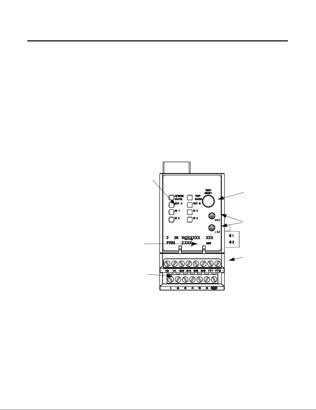
Product Overview
C
LED Status
Indicators
DeviceNet Port
Input Terminals
Test/Reset Button
Node Address
Switches (Series B
and later)
Output and PTC
Te rm in al s
Chapter
1
Introduction
Description
This chapter provides a brief overview of the features and functionality of the
EC4 Current Monitoring Relay.
The EC4 Current Monitoring Relay is a multi-function solid-state
microprocessor-based electronic current monitoring relay for loads rated from
0.4…5000 A.
Figure 1 - EC4 Feature Overview
Rockwell Automation Publication 193-UM011A-EN-P - September 2010 11
Page 11

Chapter 1 Product Overview
193 - EC4 B B
Bulletin
Number
Typ e
EC4 EC4
Current Rating
(Amps)
P 0.4…2.0
A1…5
B3…15
C5…25
D9…45
E 18…90
Z 9…5000
Bulletin 100
Contactor Size
B C09…C23
D C30…C43
E C60…C85
Z Panel Mount, CT fed
Catalog Number
Explanation
Single-/Three-Phase
Operation
Figure 2 - Catalog Number Explanation
The EC4 Current Monitoring Relay is factory-programmed to monitor
three-phase current. The installer can easily change to single-phase operation by
accessing and changing the setting of Parameter 27, Single/Three Ph. Refer to
Chapter 2 — Installation and Wiring – for typical motor connections.
Protection and Warning
Functions
Current Monitoring
Parameters
The EC4 Current Monitoring Relay provides the following protection and
warning functions:
• L(1-3) Undercurrent
• L(1-3) Overcurrent
• L(1-3) Loss
• Communication Fault/Idle
• Number of Starts (warning only)
• Number of Hours (warning only)
Refer to Chapter 3 — Protective Trip and Warning Functions and Chapter 5
— Programmable Parameters for further explanation of these functions.
The EC4 Current Monitoring Relay allows the user to monitor the following
operational data over the DeviceNet network:
• Individual phase currents (in amperes)
• Ground fault current (in amperes)
Refer to Chapter 6 — Current Monitoring Parameters for further information.
12 Rockwell Automation Publication 193-UM011A-EN-P - September 2010
Page 12

Product Overview Chapter 1
Diagnostic Parameters
Trip Relay
Inputs and Outputs
The EC4 Current Monitoring Relay allows the user to monitor the following
diagnostic information over the DeviceNet network:
• Device status
• Tri p s tat us
• Wa rn in g s ta tu s
• Elapsed Time
• Operating Hours
• History of past 5 trips and warnings
Refer to Chapter 7 — Diagnostic Parameters for detailed information of these
parameters.
When the EC4 Current Monitoring Relay is in the unpowered state, the trip relay
contact is open. The trip relay contact closes approximately 2.35 seconds after
power is applied if no trip condition exists.
In addition to the trip relay, the EC4 Current Monitoring Relay provides 4 inputs
and 2 outputs. the inputs are rated 24V DC only. For 120V AC inputs, add the
AC input interface module, Cat. No. 193-EIMD
The status of each can be monitored over the DeviceNet network through
parameter 21, Device Status, or one of the input assemblies. Additionally, the
outputs can be controlled over the network by using one of the output assemblies.
Refer to Appendix B — DeviceNet Information for listings of the available input
and output assemblies.
The EC4 Current Monitoring Relay offers added flexibility by providing the
capability to perform control functions with the inputs and outputs through
DeviceLogix.
The EC4 Current Monitoring Relay inputs are independently configurable for
Trip Reset, Remote Trip, L1 Loss Arm, L2 Loss Arm, L3 Loss Arm, L1L2 Loss
Arm, L2L3 Loss Arm, L1L3 Loss Arm, L1L2L3 Loss Arm, and normal
operation.
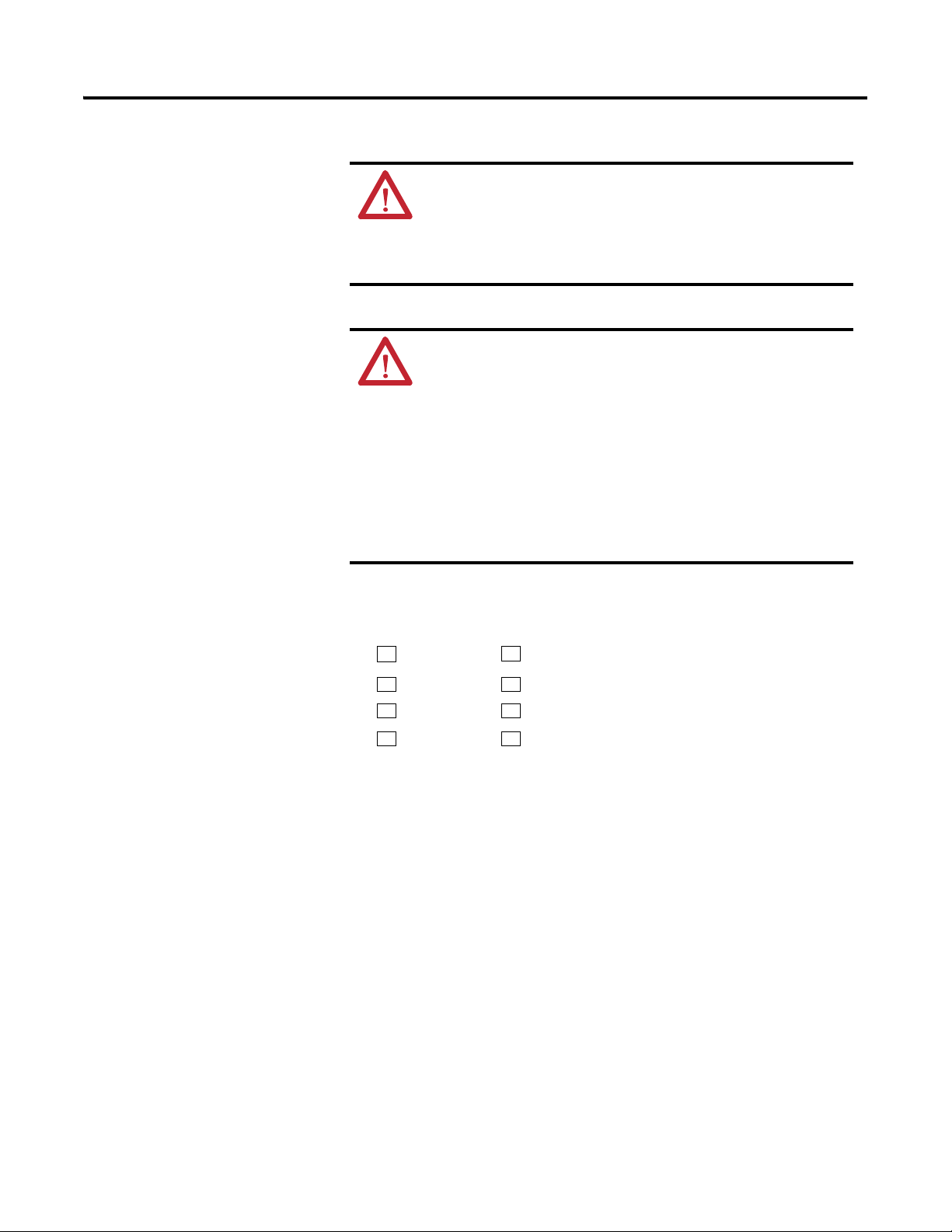
ATTENTION: If the outputs are being commanded via an
explicit message, ensure that there is no established I/O
connection that is actively controlling them, and that the explicit
message connection has a non-zero expected packet rate (EPR)
setting.
Rockwell Automation Publication 193-UM011A-EN-P - September 2010 13
Page 13
Chapter 1 Product Overview
NETWORK
STATUS
TRIP / WARN
OUT A OUT B
IN 1 IN 3
IN 2 IN 4
ATTENTION: The state of the outputs during a Protection Fault,
DeviceNet Comm Fault, or a DeviceNet Comm Idle may be
dependent on the OUTA or OUTB Pr FltState, Pr FltValue, Dn
FltState, Dn FltValue, Dn IdlState, and Dn IdlValue
programmable parameters. For details refer to the Output Setup
Group section of Chapter 5 – Programmable Parameters.
ATTENTION: The EC4 Current Monitoring Relay’s output control
firmware latches “OUT A” and “OUT B” closed upon receipt of a
network “close” command. The outputs will maintain the
commanded closed state until receipt of a network “open”
command. Parameters “OutX Pr FltState” and “OutX Pr
FltValue”, found in the EC4 Current Monitoring Relay’s Output
Setup group, allow flexibility concerning the operation of the
outputs in the event of a trip. Factory default settings cause
the outputs to open upon occurrence of a trip. EC4 outputs
that were closed prior to a trip will re-close upon trip
reset, provided that a network “open” command is not
received first.
Status Indication
The EC4 Current Monitoring Relay provides the following LED indicators:
NETWORK STATUS: This green/red LED indicates the status of the network
connection. See Chapter 11 — Troubleshooting for the possible LED
indications and the associated definitions.
TRIP / WARN: This red/amber LED flashes an amber code under a warning
condition and a red code when tripped. The warning or trip code is indicated by
the number of flashes in sequence. Refer to the side label on the product for
trip/warning codes or Chapter 11 — Troubleshooting.
OUT A and B: These amber LEDs illuminate when the output contacts are
commanded closed.
IN 1…4: These amber LEDs illuminate when the user-connected device contact
is closed.
Test/Reset Button
14 Rockwell Automation Publication 193-UM011A-EN-P - September 2010
The Test/Reset button located on the front of the EC4 Current Monitoring
Relay allows the user to perform the following:
Page 14
Product Overview Chapter 1
Te s t : If Tes t E na bl e is enabled, the trip relay contact will open if the EC4
Current Monitoring Relay is in an un-tripped condition and the
Test/Reset button is pressed. The Test/Reset button must be pressed for a
minimum of 2 seconds to activate the test function.
Reset: The trip relay contact will close if the EC4 Current Monitoring
Relay is in a tripped condition, the cause of the trip is no longer present,
and the Test/Reset button is pressed.
ATTENTION: The “Test” function associated with the Test/Reset
button is enabled by default. Activating it while a motor is
operating will cause the starting contactor to drop out and stop
motor operation.
Node Address Switches
DeviceNet Compatibility
Flash Memory
The node address switches located on the front of the EC4 Current Monitoring
Relay provides physical means for setting the device node address value. Switch
settings greater than 63 allow the node address to be software configured.
The EC4 Current Monitoring Relay supports the following DeviceNet
functionality:
• Polled I/O messaging
• Change-of-state / cyclic messaging
• Explicit messaging
• Group 4 off-line node recovery messaging
• Full parameter object support
• Auto-baud rate identification
• Configuration consistency value
• UCMM (Unconnected Message Manager)
• DeviceLogix component technology
The EC4 Current Monitoring Relay incorporates flash memory. This facilitates
updating of the product firmware as new revisions are released.
Rockwell Automation Publication 193-UM011A-EN-P - September 2010 15
Page 15

Installation and Wiring
Chapter
2
Introduction
Receiving
Unpacking/Inspecting
Storing
This chapter provides instructions for receiving, unpacking, inspecting, and
storing the EC4 Current Monitoring Relay. Installation and wiring instructions
for common applications are also included.
It is the responsibility of the user to thoroughly inspect the equipment before
accepting the shipment from the freight company. Check the item(s) received
against the purchase order. If any items are damaged, it is the responsibility of the
user not to accept delivery until the freight agent has noted the damage on the
freight bill. Should any concealed damage be found during unpacking, it is again
the responsibility of the user to notify the freight agent. The shipping container
must be left intact and the freight agent should be requested to make a visual
inspection of the equipment.
Remove all packing material from around the EC4 Current Monitoring Relay.
After unpacking, check the item’s nameplate catalog number against the purchase
order.
The EC4 Current Monitoring Relay should remain in its shipping container
prior to installation. If the equipment is not to be used for a period of time, it
must be stored according to the following instructions in order to maintain
warranty coverage:
• Store in a clean, dry location.
• Store within an ambient temperature range of -40°C…+85°C
(-40°…+185°F).
• Store within a relative humidity range of 0…95%, non-condensing.
• Do not store where the device could be exposed to a corrosive atmosphere.
• Do not store in a construction area.
General Precautions
In addition to the specific precautions listed throughout this manual, the
following general statements must be observed.
Rockwell Automation Publication 193-UM011A-EN-P - September 2010 16
Page 16
Installation and Wiring Chapter 2
ATTENTION: The EC4 Current Monitoring Relay contains ESD
(electrostatic discharge) -sensitive parts and assemblies. Static
control precautions are required when installing, testing,
servicing, or repairing this assembly. Component damage may
result if ESD control procedures are not followed. If you are not
familiar with static control procedures, refer to Allen-Bradley
publication 8200-4.5.2, “Guarding Against Electrostatic
Damage”, or any other applicable ESD protection handbook.
ATTENTION: An incorrectly applied or installed EC4 Current
Monitoring Relay can result in damage to the components or
reduction in product life. Wiring or application errors, such as
supplying incorrect or inadequate DeviceNet supply voltage,
connecting an external supply voltage to the input, or
operating/storing in excessive ambient temperatures may result
in malfunction of the EC4 Current Monitoring Relay.
ATTENTION: Only personnel familiar with the EC4 Current
Monitoring Relay and associated machinery should plan to
install, start up, and maintain the system. Failure to comply may
result in personal injury and/or equipment damage.
Starter Installation
ATTENTION: The purpose of this user manual is to serve as a
guide for proper installation. The National Electrical Code and
any other governing regional or local code will overrule this
information. Rockwell Automation cannot assume responsibility
for the compliance or proper installation of the EC4 Current
Monitoring Relay or associated equipment. A hazard of personal
injury and/or equipment damage exists if codes are ignored
during installation.
ATTENTION: The Earth Ground terminal of the EC4 Current
Monitoring Relay shall be connected to a solid earth ground via
a low-impedance connection.
The following figures and tables illustrate the starter assembly instructions and
approximate dimensions.
Rockwell Automation Publication 193-UM011A-EN-P - September 2010 17
Page 17
Chapter 2 Installation and Wiring
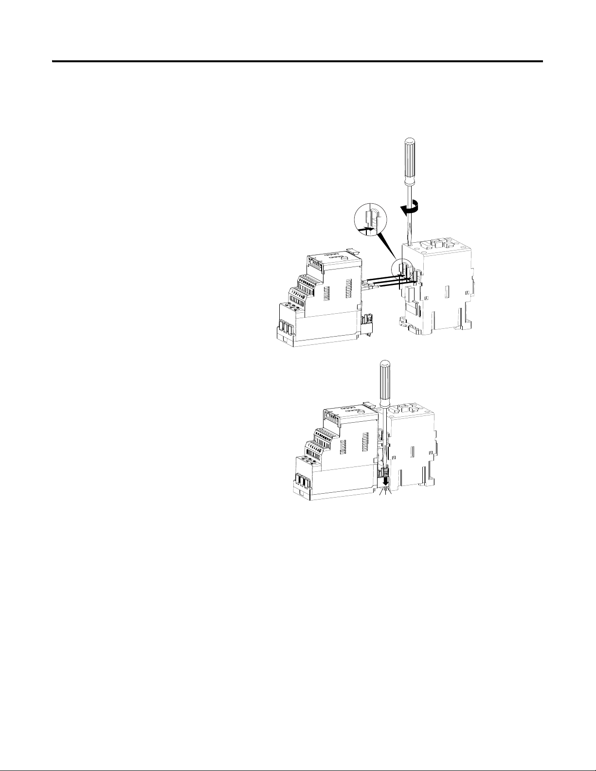
CLICK
➊
➋
➌
2.5 N•m
22 lb•in
Starter Assembly Instructions
Figure 3 - 100-C09…C43 Starter Assembly Instructions (for use with Cat. Nos.
193-EC_ _B and -EC_ _D)
18 Rockwell Automation Publication 193-UM011A-EN-P - September 2010
Page 18
Installation and Wiring Chapter 2
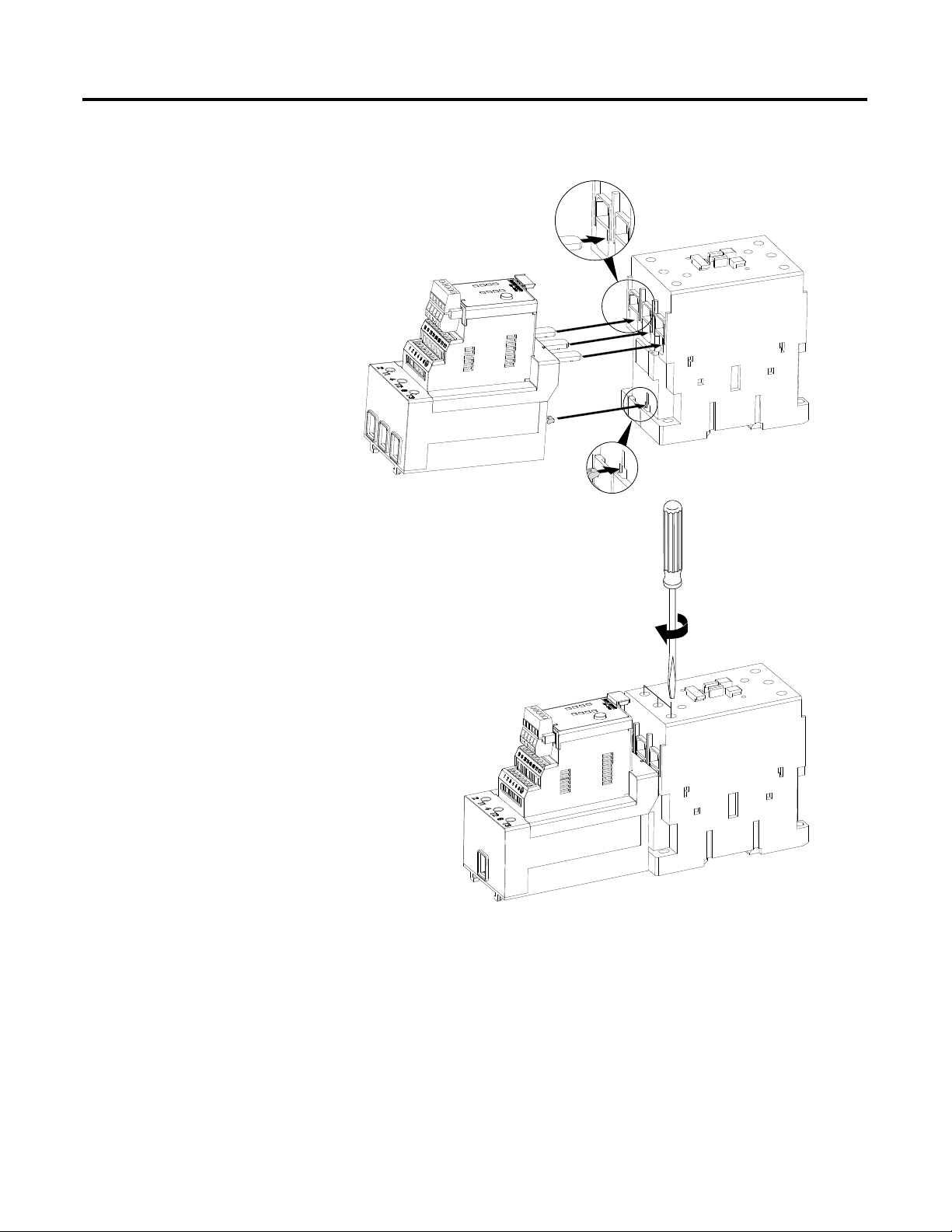
➊
➋
4 N•m
35 lb•in
Figure 4 - 100-C60…C85 Starter Assembly Instructions (for use with Cat. No.
193-EC_ _E)
Rockwell Automation Publication 193-UM011A-EN-P - September 2010 19
Page 19
Chapter 2 Installation and Wiring
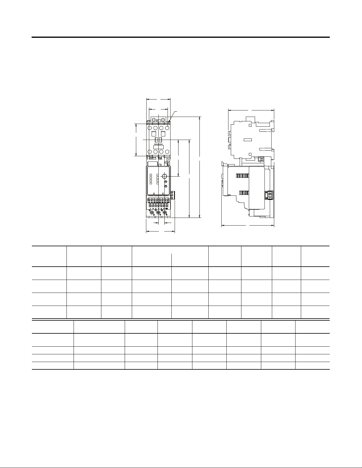
AA
D2D2
D1D1
F1F1
E2E2
B1B1
B
1E
Ø
D
H
C
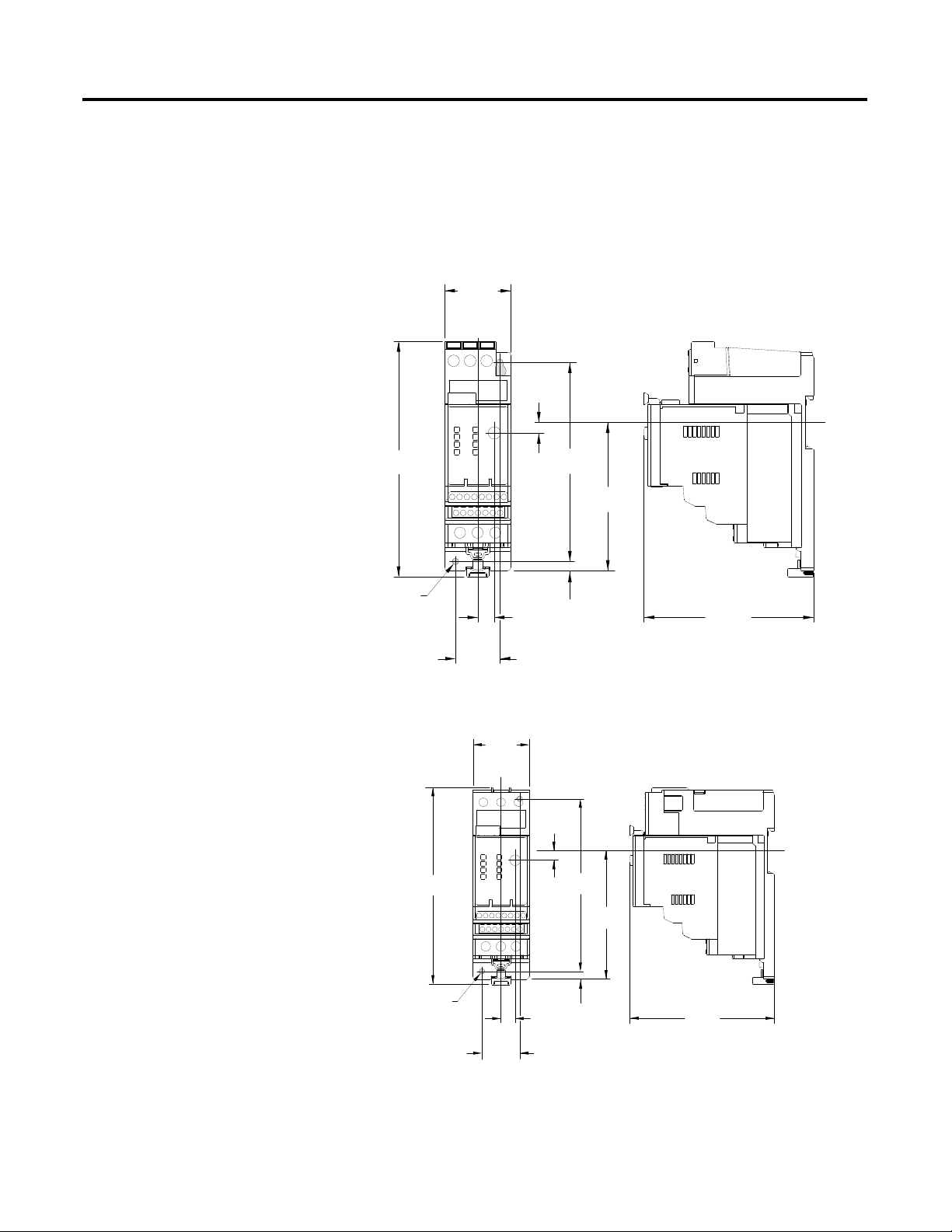
Starter Approximate Dimensions
Approximate dimensions are shown in millimeters (inches). Dimensions are not
intended to be used for manufacturing purposes.
Figure 5 - Bulletin 109 Approximate Starter Dimensions
Table 1 - Bulletin 109 Approximate Starter Dimensions
Overload Cat.
No.
193-EC_ _B 100-C09, -C12
193-EC_ _D 100-C30, -C37 45 (1-25/32) 188.3 (7-13/32) 207.7 (8-11/64) 145.1
193-EC_ _D 100-C43 54 (2-1/8) 188.3 (7-13/32) 207.7 (8-11/64) 145.1
193-EC_ _E 100-C60, -C72,
Overload Cat.
No.
193-EC_ _B 100-C09, -C12 -C16,
193-EC_ _D 100-C30, -C37 53.2 (2-3/32) 60 (2-23/64) 35 (1-3/8) 104 (4-3/32) 2 (5/64) Ø4.2 (11/64Ø)
193-EC_ _D 100-C43 62.2 (2-7/16) 60 (2-23/64) 45 (1-25/32) 107 (4-7/32) 2 (5/64) Ø4.2 (11/64Ø)
193-EC_ _E 100-C60, -C72, -C85 80.2 (3-9/64) 100 (3-15/16) 55 (2-11/64) 125.5 (4-15/16) 2 (5/64) Ø5.5 (7/32Ø)
Contactor
Cat. No.
Width A Height B B1 Depth C E1 E2
without
with 193-EIMD
193-EIMD
-C16, -C23
45 (1-25/32) 188.3 (7-13/32) 207.7 (8-11/64) 145.1
(5-23/32)
107 (4-7/32) 11.4 (29/64) 67.9
107 (4-7/32) 11.4 (29/64) 67.9
(5-23/32)
107 (4-7/32) 11.4 (29/64) 67.9
(5-23/32)
-C85
72 (2-53/64) 236.1 (9-19/64) 255.5 (10-1/16) 173.2
(6-13/16)
124.6
(4-29/32)
11.4 (29/64) 89.8
Contactor Cat. No. F1 D1 D2 H J ØD
53.2 (2-3/32) 60 (2-23/64) 35 (1-3/8) 85.1 (3-23/64) 2 (5/64) Ø4.2 (11/64Ø)
-C23
(2-43/64)
(2-43/64)
(2-43/64)
(3-17/32)
20 Rockwell Automation Publication 193-UM011A-EN-P - September 2010
Page 20
Installation and Wiring Chapter 2
45
(1-25/32)
159.3
(6-17/64)
7.3
(9/32)
135
(5-5/16)
6.1
(1/4)
100.5
(3-31/32)
ø 4.4
(11/64 ø)
11.4
(29/64)
30
(1-3/16)
115
(4-17/32)
115
(4-17/32)
11.4
(29/64)
30
(1-3/16)
45
(1-25/32)
7.3
(9-32)
135
(5-5/16)
154.2
(6-5/64)
ø 4.4
(11/64 ø)
100.5
(3-31/32)
6.1
(1/4)
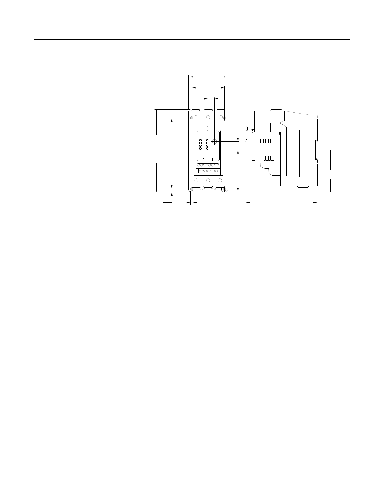
Separate Mount Adapter Approximate Dimensions
Approximate dimensions are shown in millimeters (inches). Dimensions are not
intended to be used for manufacturing purposes.
Figure 6 - 193-ECPM1 Panel Mount Adapter Approximate Dimensions (for use with
Cat. No. 193-EC_ _B)
Figure 7 - 193-ECPM2 Panel Mount Adapter Approximate Dimensions (for use with
Cat. No. 193-EC_ _D and 193-EC_ _Z)
Rockwell Automation Publication 193-UM011A-EN-P - September 2010 21
Page 21
Chapter 2 Installation and Wiring
71.7
(2-53/64)
131.2
(5-11/64)
15
(19/32)
77
(3 - 1/32)
ø 5.5
(7/32 ø)
5
(13/64)
60
(2-23/64)
11.4
(29/64)
150.5
(5-15/16)
130
(5-1/8)
77
(3-1/32)
155.1
(6-7/64) w/
193-EIMD
Figure 8 - 193-ECPM3 Panel Mount Adapter Approximate Dimensions (for use with
Cat. No. 193-EC_ _E)
22 Rockwell Automation Publication 193-UM011A-EN-P - September 2010
Page 22
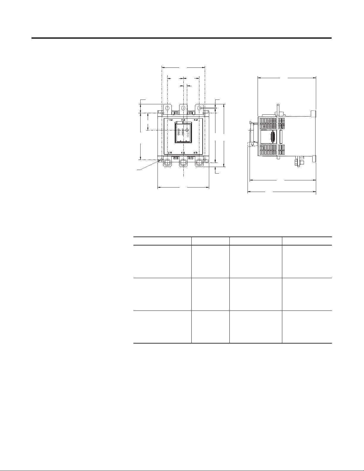
Figure 9 - Wire Size and Torque Specifications
A
B
M
N
P
C
L
K
D
E
E
F
I
G
H
J
0
2
4
6
8
0
2
4
6
8
Installation and Wiring Chapter 2
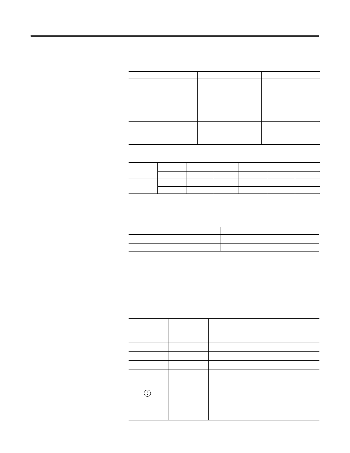
Power Terminals
Table 2 - Power Terminal Wire Size and Torque Specification
Cat. No.
Stranded/Solid
AWG
Single Conductor
Tor qu e
Multiple
Conductor
Tor qu e
Flexible-Stranded with
Ferrule
Metric
Single Conductor
Tor qu e
Multiple
Conductor
Tor qu e
Coarse-Stranded/Solid
Metric
Single Conductor
Tor qu e
Multiple
Conductor
Tor qu e
193-EC
_ _B, -EC_ _D 193-EC_ _E
#14...6 AWG
22 lb-in
#10...6 AWG
30 lb-in
2.5...16 mm
2
2.5 N•m
6...10 mm
2
3.4 N•m
2.5...25 mm
2
2.5 N•m
6...16 mm
2
3.4 N•m
#12...1 AWG
35 lb-in
#6...2 AWG
35 lb-in
4...35 mm
2
4 N•m
4...25 mm
2
4 N•m
4...50 mm
2
4 N•m
4...35 mm
2
4 N•m
Rockwell Automation Publication 193-UM011A-EN-P - September 2010 23
Page 23
Chapter 2 Installation and Wiring
Control and DeviceNet Terminals
Table 3 - Control and DeviceNet Terminal Wire Size and Torque Specification
Cat. No. All Types
Stranded/Solid
AWG
Flexible-Stranded with Ferrule
Metric
Coarse-Stranded/Solid
Metric
Table 4 - Maximum Wire Lengths (Input)
Single Conductor
Multiple Conductor
To rq ue
Single Conductor
Multiple Conductor
To rq ue
Single Conductor
Multiple Conductor
To rq ue
24...12 AWG
24...16 AWG
5 lb-in
0.25...2.5 mm
0.5...0.75 mm
0.55 Nm
0.2...4.0 mm
0.2...1.5 mm
0.55 Nm
2
2
2
2
Terminal Designations
Min. Cross
Section
Max.
Length ➊
2
mm
AWG 20 18 16 14 12
m 160 250 400 600 1000
ft 525 825 1300 1950 3200
0.5 0.75 1.5 2.5 4.0
For reliable input signal processing, input wiring should be routed in raceways
separate from power cabling.
Table 5 - Ground Fault Sensor Terminals (S1 and S2)
Wire type Shielded, twisted pair
Cross section
To rq ue
0.2…4.0 mm
0.55 N•m (5 lb-in.)
2
(#24…12 AWG)
Control Terminals
The following table defines the EC4 Current Monitoring Relay control terminal
designations.
Table 6 - Control Terminal Designation
Terminal
Designation
1 IN 1 General-purpose sinking input number 1
2 IN 2 General-purpose sinking input number 2
3 IN 3 General-purpose sinking input number 3
4 IN 4 General-purpose sinking input number 4
5 V+ +24V DC supply for inputs
6V+
Reference Description
End Earth Ground
➊
13/14 OUT A Output A
23/24 OUT B Output B
24 Rockwell Automation Publication 193-UM011A-EN-P - September 2010
Page 24

Table 6 - Control Terminal Designation
Installation and Wiring Chapter 2
Terminal
Designation
95/96 Trip Relay Trip Relay
IT1/IT2 — —
S1/S2 — External ground fault sensor input
➊ An earth ground connection to this terminal will assist in obtaining compliance with Electromagnetic
Compatibility requirements.
Reference Description
DeviceNet Terminals
The following table defines the DeviceNet connector terminal designations.
Table 7 - DeviceNet Terminal Designation
Terminal Signal Function Color
1V-CommonBlack
2 CAN_L Signal Low Blue
3 Drain Shield Non-insulated
4 CAN_H Signal High White
5 V+ Power Supply Red
Grounding
Short-Circuit Ratings
The following grounding recommendations are provided to ensure
Electromagnetic Compatibility compliance during installation:
• The earth ground terminal of the EC4 Current Monitoring Relay shall be
connected to a solid earth ground via a low-impedance connection
• Installations employing an external ground fault sensor shall ground the
cable shield at the sensor with no connection made at the EC4 Current
Monitoring Relay
The EC4 Current Monitoring Relay is suitable for use on circuits capable of
delivering not more than the RMS symmetrical amperes listed in the following
tables.
Table 8 - UL Short-Circuit Ratings
Cat. No. Maximum Available Fault
_ _B
193-EC
193-EC
_ _D
_ _E
193-EC
_ _Z
193-EC
Current [A]
5,000 600
5,000 600
10,000 600
5,000 600
Maximum Voltage
[V]
Rockwell Automation Publication 193-UM011A-EN-P - September 2010 25
Page 25
Chapter 2 Installation and Wiring
Table 9 - IEC Short-Circuit Ratings
Fuse Coordination
Cat. No. Prospective Current
193-EC_ _B
_ _D
193-EC
193-EC_ _E
Ir [A]
1,000 100,000 690
3,000 100,000 690
5,000 100,000 690
Conditional Short
Circuit Current I
[A]
Maximum Voltage
[V]
q
The following table illustrates the Type I and Type II fuse coordination when
used in conjunction with Bulletin 100-C contactors.
Table 10 - Type I and Type II Fuse Coordination with 100-C and 100-D Contactors
Overload
Cat. No.
193-EC_ _B
_ _D
193-EC
_ _E
193-EC
Contactor
Cat. No.
100-C09 1,000 100,000 20 20
100-C12 1,000 100,000 25 25
100-C16 1,000 100,000 35 35
100-C23 3,000 100,000 40 40
100-C30 3,000 100,000 60 60
100-C37 3,000 100,000 80 80
100-C43 3,000 100,000 90 90
100-C60 3,000 100,000 125 125
100-C72 5,000 100,000 150 150
100-C85 5,000 100,000 175 175
Prospective
Current
[A]
I
r
Conditional
Short Circuit
Current
Iq [A]
Type I
Class J or CC
[A]
Type II
Class J or CC
[A]
Typical Motor Connections
ATTENTION: Select the motor branch circuit protection that
complies with the National Electrical Code and any other
governing regional or local codes.
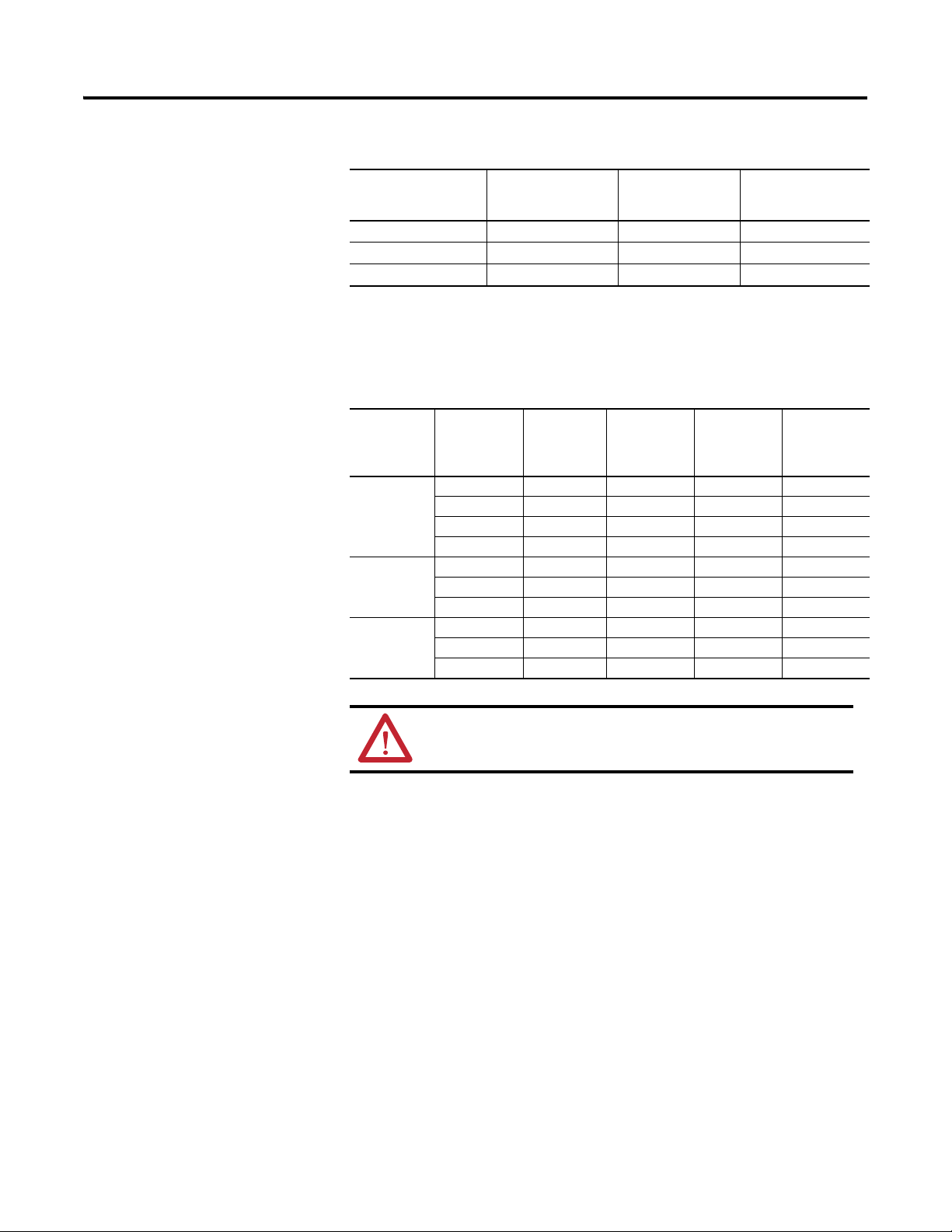
Three-Phase Direct-on-Line (D.O.L)
The following figure illustrates the EC4 Current Monitoring Relay typical motor
connections in a three-phase D.O.L application.
26 Rockwell Automation Publication 193-UM011A-EN-P - September 2010
Page 26
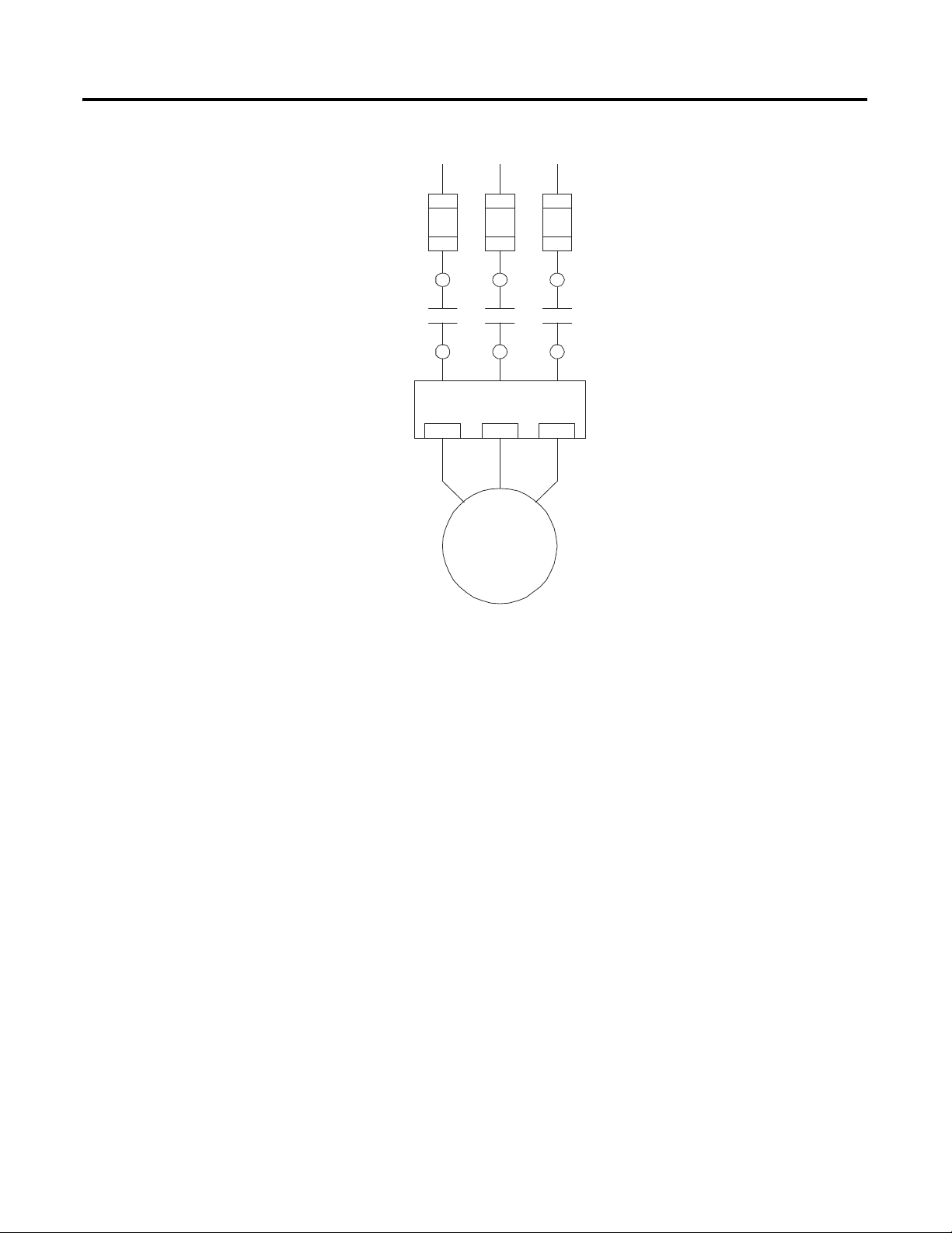
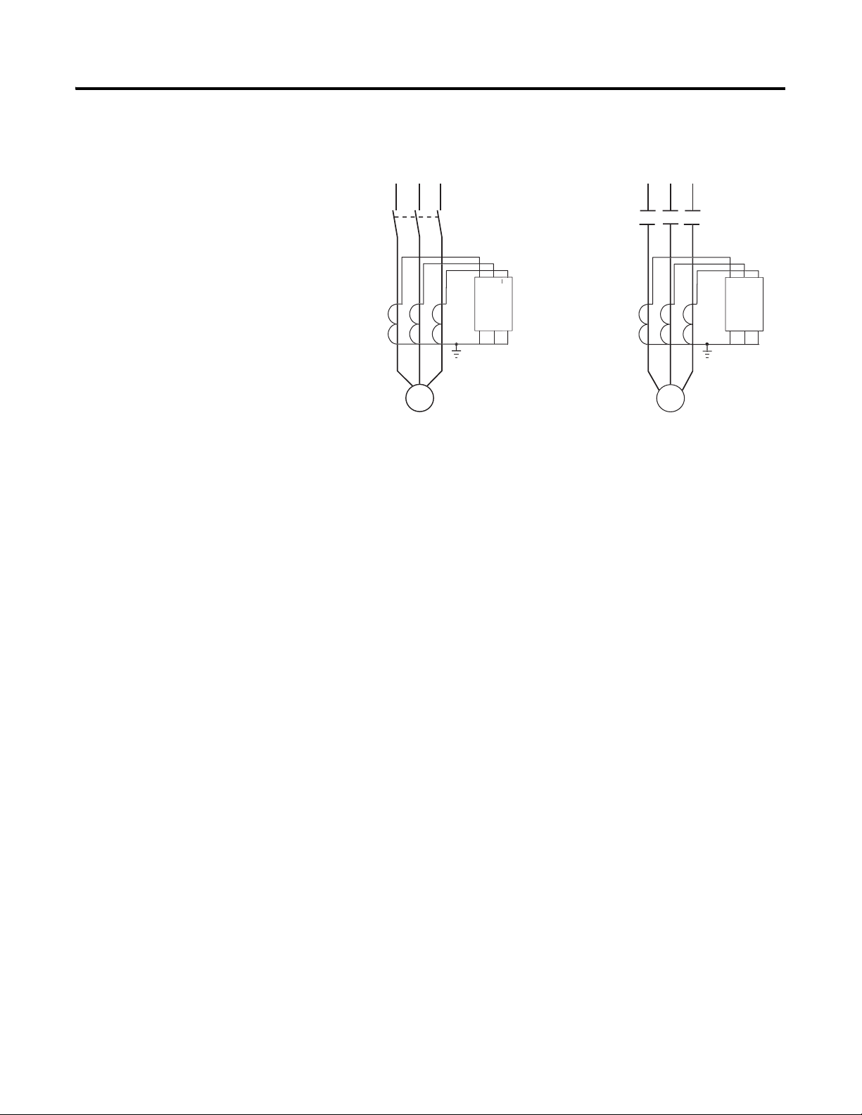
Figure 10 - Three-Phase D.O.L Wiring Diagram
S.C.P.D.
E3 / E3 Plus
L1 L2 L3
2/T1 4/T2 6/T3
M
T1
T2
T3
Installation and Wiring Chapter 2
Single-Phase Full-Voltage
The following figure illustrates the EC4 Current Monitoring Relay Typical
motor connections in a single-phase full voltage application.
Rockwell Automation Publication 193-UM011A-EN-P - September 2010 27
Page 27
Chapter 2 Installation and Wiring
IMPORTANT
IMPORTANT
S.C.P.D.
E3 / E3 Plus
L1 L2
2/T1 4/T2 6/T3
M
T1 T2
Figure 11 - Single-Phase Full-Voltage Wiring Diagram
External Line Current
Transformer Application
Parameter 27, Single/Three Ph, should be set to single-phase.
Traditional single-phase wiring (connecting T2 to L3) will result in a
vector imbalance of current flowing through the EC4 Current Monitoring
Relay. This will result in inaccurate ground fault reporting and protection.
EC4 Current Monitoring Relays are designed for use with separately mounted,
customer-supplied line current transformers (CTs) as required in higher-current
applications. The FLA setting range is 9…5000 A for these units, with a legal
setting range per current transformer. Parameter 78, CT Ratio, is provided for
setting the current transformer ratio to be installed.
Current Transformer Specifications
The 193-EC_ZZ current monitoring relays are intended for use with CTs with a
secondary current rating of 5 A. The installer shall provide one CT for each
motor phase and shall connect the CT’s secondary leads to the appropriate EC4
Current Monitoring Relay power terminals as shown in . The CTs shall have an
appropriate ratio rating as detailed in Table 3.1. Additionally, the CT shall be
selected to be capable of providing the required VA to the secondary load, which
includes the EC4 Current Monitoring Relay burden of 0.1 VA at the rated
28 Rockwell Automation Publication 193-UM011A-EN-P - September 2010
Page 28
Installation and Wiring Chapter 2
6x
6x
OR
y
C
t
s
d
y
secondary current and the wiring burden. Finally, the CT shall be rated for
protective relaying to accommodate the high inrush currents associated with
motor startup and shall have an accuracy of
≤±2% over its normal operating
range. Typical CT ratings include:
ANSI (USA) Class C5 B0.1
CSA (Canada) Class 10L5
IEC (Europe) 5 VA Class 5P10
ATTENTION: The improper selection of a current transformer can
result in the EC4 Current Monitoring Relay reporting inaccurate
motor operational data, and possible motor damage. The selected
current transformer must be rated for protective relaying
applications.
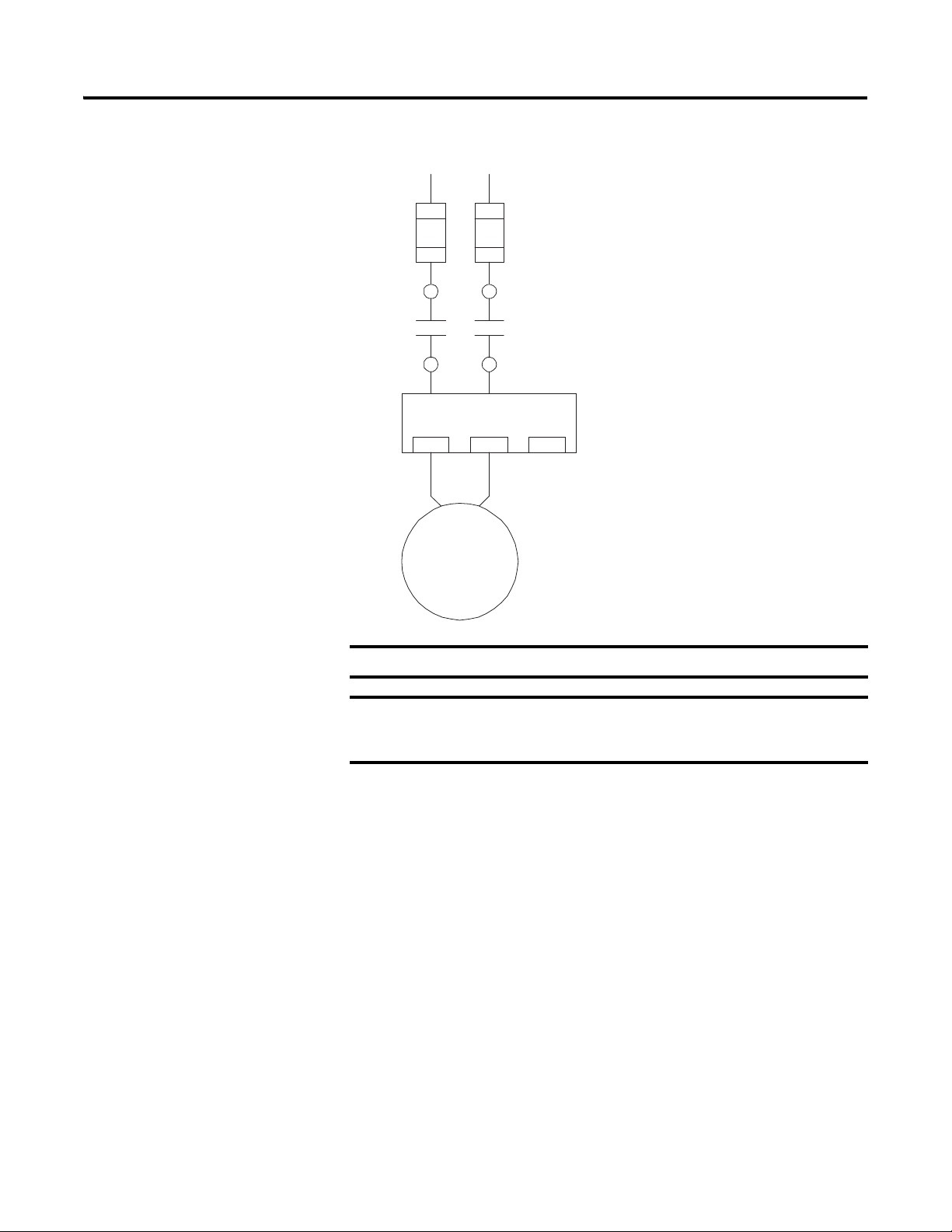
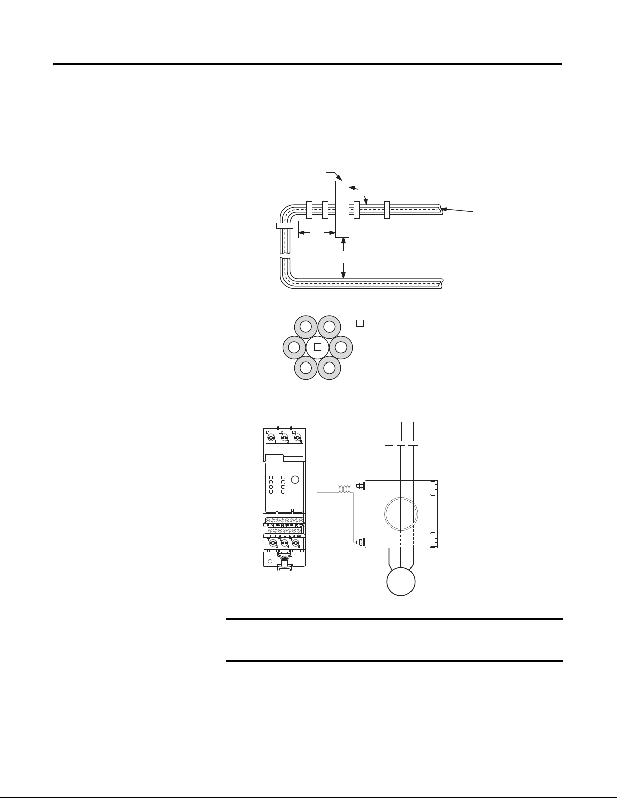
Installation Instructions
Cat. No. 193-EC_ZZ current monitoring relays are designed to be installed in
cat. no. 193-ECPM2 panel mount adapters and connected to separately mounted
current transformers. For panel mount adapter assembly, refer to the instructions
included with the panel mount adapter.The EC4 Current Monitoring Relay must
be mounted a distance equal to or greater than six times the cable diameter
(including insulation) from the nearest current-carrying conductor or current
transformer. For applications employing multiple conductors per phase, the
diameter of each cable should be added and multiplied by six to determine the
proper placement distance for the EC4 Current Monitoring Relay.
Figure 12 - Cat. No. 193-EC_ZZ Current Monitoring Relay Mounting Placement
Primar
urren
Transformer
E3 Overloa
Rela
ATTENTION: Placement of the EC4 Current Monitoring Relay
closer than the recommended distance of six times the cable
diameter may compromise its current reporting and protection
capabilities.
Rockwell Automation Publication 193-UM011A-EN-P - September 2010 29
Page 29
Chapter 2 Installation and Wiring
C
3
3
3E3
/2
3
/4
T
/1L2/3
L
3/6
/1L2/3L3/5
y
C
t
s
y
C
t
s
Figure 13 - External CT Connection Diagrams
IE
L
L
External Ground Fault
Sensor Application
Primar
urren
Transformer
L1
E
T1
T2
Primar
urren
Transformer
T
L1
T1/2T2/4T
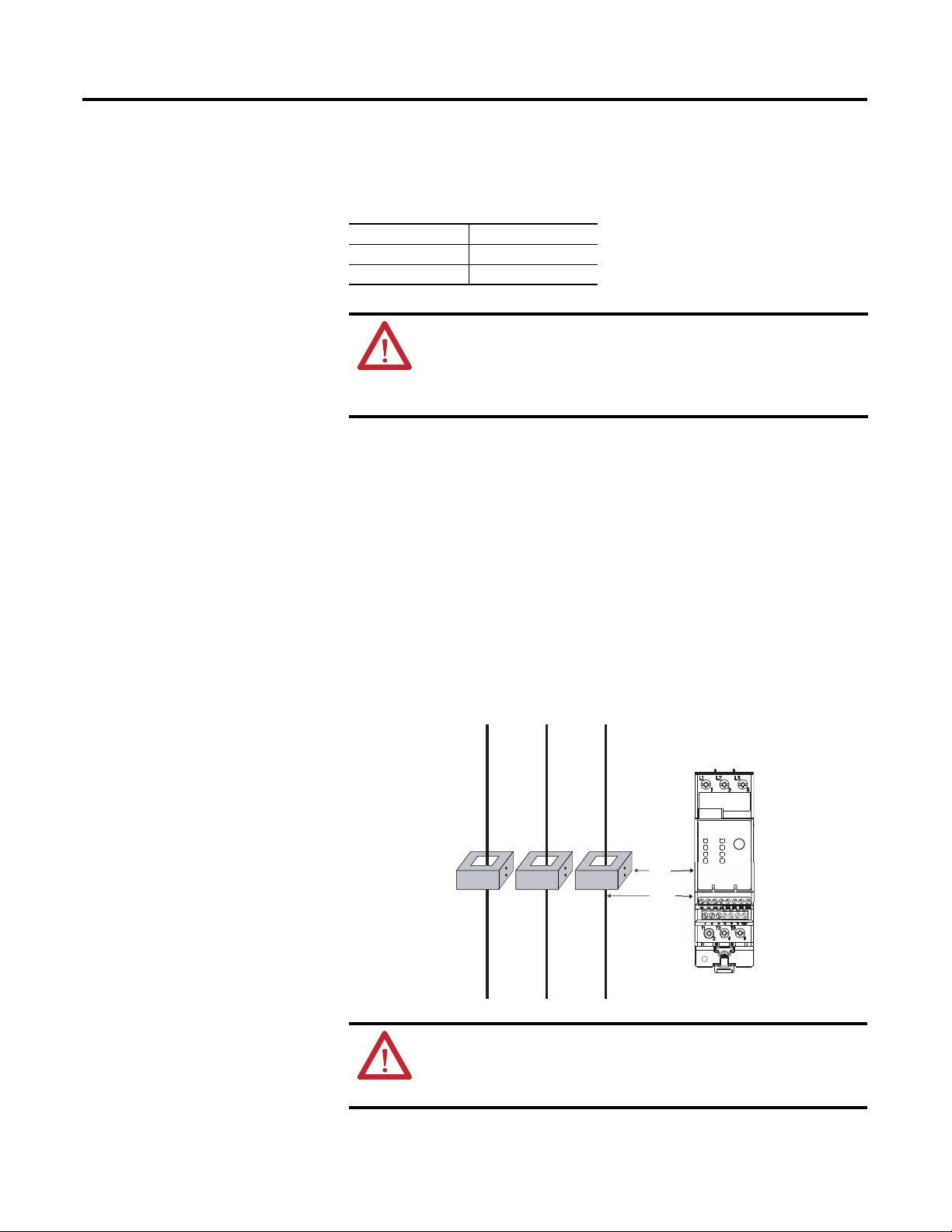
EC4 Current Monitoring Relays are intended to provide ground fault protection
when used with the Cat. No. 193-CBCT_ external ground fault (core balance)
sensor. The ground fault sensor mounts separately from the EC4 current
monotoring relay and must be placed within three meters of it. The
customer-supplied cable for wiring the ground fault sensor to the EC4 should
meet the specifications outlined in Table 5.
Power Cable Installation Instructions
1. All power cables (including the neutral when used) must pass through the
sensor window. The equipment ground conductor (the conductor used to
carry the non-current-carrying metal parts of equipment, as defined by
Article 100 of the NEC) must not pass through the sensor window.
2. The power cables through the sensor window should be straight, tightly
bundled, centered in the window, and perpendicular to the sensor for a
length equal to or greater than six times the cable diameter (including
insulation) from the sensor.
3. All other conductors with available fault currents in excess of 1 000 A
should be placed a distance equal to or greater than six times the cable
diameter (including insulation) from the sensor.
4. The power cables of the branch circuit to be protected by the EC4 Current
Monitoring Relay must not be grounded on the load side of the ground
fault sensor.
5. If the power cables are enclosed in a conducting jacket, the jacket must be
grounded on the line side of the sensor. The jacket must not pass through
the sensor window, but must be cut at the window and joined with a
conductor that passes outside the sensor window.
30 Rockwell Automation Publication 193-UM011A-EN-P - September 2010
Page 30
Installation and Wiring Chapter 2
IMPORTANT
L1
L2 L2
L3
L3 L1
1
1
The spacer is a short (approximately 10 times
the cable diameter in length) piece of cable
with no connections to any terminal.
6. The power system may be solidly grounded or grounded through an
impedance at its source as long as the impedance allows a magnitude of
current to flow that is within the 20 mA…5 A operational range of the
EC4 Current Monitoring Relay.
Figure 14 - Ground Fault Sensor Mounting Placement
GF Sensor
90˚
Power
Cables
6x
6x
Figure 15 - Power Cable Configuration — Two Cables per Phase
Rockwell Automation Publication 193-UM011A-EN-P - September 2010 31
Figure 16 - Ground Fault Sensor Wiring to the EC4 Current Monitoring Relay
L2 L3L1
S1
S2
E3 Plus Overload Relay
Motor
Cat. No. 193-CBCT_
Ground Fault Sensor
The shield of the twisted pair cable must be connected to earth ground
at the sensor, with no connection made at the EC4 Current Monitoring
Relay.
Maximum length of the shielded cable is 100 ft. All control terminals are for
copper wire only in sizes #12…24 AWG. Ring lug termination is required for the
ground sensor terminals of Cat. Nos. 193-CBCT2 and larger. Sensor fastener
torque: 26…30 lb-in. Cat. No. 193-CBCT1 wires should be twisted before
termination by applying one twist per inch.
Page 31

Chapter 2 Installation and Wiring
Catalog Number
Maximum
Current
Frequency
Turns
Ratio
Sensor Window I.D. Sensor Type
Maximum Recommended
Cable Size
Ref: IEC Contactor
Catalog Number
Ref: NEMA
Contactor Size
193-CBCT2
193-CBCT3
#2 AWG (35 mm
2
) @ 600V
100-C09…100-C37
100-C09…100-C85
00…2
00…3
100-C09…100-D180 00…4
193-CBCT1 45 A 50/60 Hz 1000:1
1000:150/60 Hz
90 A
#8 AWG (10 mm2) @ 600V
For a three-phase system with one cable per phase.
39.6 mm (1.56 in.)
19.1 mm (.75 in.)
For a three-phase system with two cables per phase.
#250MCM (120 mm2) @ 600V
100-C09…100-D420 00…5
#350MCM (185 mm
2
) @ 600V
1000:150/60 Hz
180 A
63.5 mm (2.50 in.)
193-CBCT4
1000:150/60 Hz420 A 82.3 mm (3.25 in.)
45.3
(1.78)
23.1
(.91)
Ø 19.1
(Ø .75)
Ø 44.5
(Ø 1.75)
63.5
(2.50)
50.8
(2.00)
3.2
(.12)
4
(.16)
12.7
(.50)
Cat. No. 193-CBCT1
Figure 17 - Control Wire Installation
Figure 18 - Cat. No. 193-CBCT1 Approximate Dimensions [mm (in.)]
32 Rockwell Automation Publication 193-UM011A-EN-P - September 2010
Page 32

Installation and Wiring Chapter 2
11.8
(.47)
3.2
(.13)
Ø D
5.3
(.21)
E
FB
A
C
96
(3.78)
Cat. No.
193-CBCT2
A
89.6
(3.53)
B
48.3
(1.90)
C
Dimensions
39.6
(1.56)
ø D
54.6
(2.15)
E
69.9
(2.75)
122.4
(4.82)
193-CBCT3
115.9
(4.56)
59.7
(2.35)
63.5
(2.50)
54.1
(2.13)96(3.78)
F
44.5
(1.75)
56.2
(2.21)
74.4
(2.93)
123.2
(4.85)
96.7
(3.81)
Cat. No. 193-CBCT4
11.8
(.47)
146.8
(5.78)
143.5
(5.65)
5.5
(.22)
74.9
(2.95)
3.2
(.13)
82.6
(3.25)
Figure 19 - Cat. No. 193-CBCT2, -CBCT3 Approximate Dimensions [mm (in.)]
Figure 20 - Cat. No. 193-CBCT4 Approximate Dimensions [mm (in.)]
Typical Control Circuit
Wiring Diagrams
Rockwell Automation Publication 193-UM011A-EN-P - September 2010 33
ATTENTION: The ratings of the EC4 Current Monitoring Relay’s
output and trip relay must not be exceeded. If the coil current or
voltage of the contactor exceeds the relay’s ratings, an
interposing relay must be used.
ATTENTION: When the power is applied to the EC4 Current
Monitoring Relay (DeviceNet terminals V+ and V-), the N.O. trip
relay contact across terminals 95 and 96 will close after
approximately 2.35 seconds if no trip condition exists.
Page 33

Chapter 2 Installation and Wiring
S.C.P.D.
E3 / E3 Plus
L1 L2
2/T1 4/T2 6/T3
M
T1 T2
S.C.P.D.
E3 / E3 Plus
L1 L2 L3
2/T1 4/T2 6/T3
M
T1T2T3
M
95 96A1 A21413
Out A Trip Relay ➊
E3 E3
➊ Contact shown with supply voltage applied.
Single-Phase
Three-Phase
95
96
A1
A2
14
13
Out A
Trip Relay ➋
E3
E3
➋
Contact shown with supply voltage applied.
K
L1
N
ATTENTION: Additional control circuit protection may be
required. Refer to the applicable electrical codes.
ATTENTION: Do not apply external voltage to 1T1, 1T2, or the
input terminals IN 1…4. This may cause equipment damage.
Full-Voltage Non-Reversing (with Network Control)
Figure 21 - Full-Voltage Non-Reversing Starter Wiring Diagram (NEMA
Nomenclature)
Figure 22 - Full-Voltage Non-Reversing Starter Wiring Diagram (CENELEC
Nomenclature)
34 Rockwell Automation Publication 193-UM011A-EN-P - September 2010
Page 34

Installation and Wiring Chapter 2
IMPORTANT
Reset
1- 5
External/Remote Reset (FRN 3.001 and later)
To reset a trip from an external/remote location, configure one of the EC4
Current Monitoring Relay’s inputs for trip reset operation using one of
parameters 83…86. Wire the input as shown in Figure 23 .
Figure 23 - External/Remote Reset Wiring
Reset operation is edge sensitive and trip free; that is, holding the
push button down (maintaining the reset contact in a closed position)
will not prevent the EC4 Current Monitoring Relay from tripping.
Rockwell Automation Publication 193-UM011A-EN-P - September 2010 35
Page 35

Chapter
IMPORTANT
Protective Trip and Warning Functions
3
Introduction
Trip Enable
The purpose of this chapter is to provide detailed information regarding the
protective trip and warning functions of the EC4 Current Monitoring Relay. In
this chapter, you will find considerable mention given to programming
parameters as they relate to these functions. For complete descriptions of the
programming parameters, refer to Chapter 5 — Programmable Parameters.
Parameter 24, Tri p E nable, allows the installer to enable or disable the desired
protective functions separately. The overcurrent, undercurrent, and
communication fault trip functions are enabled from the factory.
The EC4 Current Monitoring Relay requires undercurrent
(UC)/overcurrent (OC) to be enabled at all times. The EC4 Current
Monitoring Relay requires either UC/OC to be enabled at all times.
ATTENTION: The Trip Enable settings should not be altered during
machine operation, as unexpected behavior of the outputs could
occur. This may result in an unintended actuation of controlled
industrial equipment, with the potential for machine damage or
serious injury to personnel.
Warning Enable
Overcurrent Protection
Rockwell Automation Publication 193-UM011A-EN-P - September 2010 36
Parameter 25, Wa r ni n g E n a bl e , allows the installer to enable or disable the desired
warning functions separately. All warning functions are disabled from the factory.
The EC4 Current Monitoring Relay provides UC/OC protection through true
RMS current measurement of the individual phase currents of the connected
loads. For Undercurrent & Overcurrent Trip and Warning Level parameters, a
warning or trip will occur when the programmed conditions are satisfied.
Page 36

Protective Trip and Warning Functions Chapter 3
Table 11 - Overcurrent Setting Ranges
Current Range [A] Min. [A] Max. [A] Default [A]
0.4…2 0.4 2.5 0.4
1…5 1 6.25 1
3…15 3 18.75 3
5…25 5 31.25 5
9…45 9 56.25 9
18…90 18 112.5 18
9…5000 9 6250 9
Overcurrent Warning
The EC4 Current Monitoring Relay will issue a warning with an overcurrent
condition if:
• The current in any of the phases exceeds the current specified for the
corresponding OC Warn Level parameter (Parameter 120 for L1,
parameter 123 for L2, & parameter 126 for L3)
• No warning condition already exists
If an overcurrent warning parameter is satisfied, the following will occur:
• The TRIP/WARN LED will flash a yellow blinking pattern depending on
which phase encountered the overcurrent warning condition
– 5 blinks for L1 overcurrent
– 6 blinks for L2 overcurrent
– 7 blinks for L3 overcurrent
• Parameter 15, Warning Status, will change
– Bit 4 will go to "1" for L1 overcurrent
– Bit 5 will go to "1" for L2 overcurrent
– Bit 6 will go to "1" for L3 overcurrent
• Bit _ in Parameter 21, Device Status, will go to "1"
Overcurrent Trip
The EC4 Current Monitoring Relay will trip with an overcurrent indication if:
• The current in any of the phases exceeds the current specified for the
corresponding OC Trip Level parameter (Parameter 118 for L1, parameter
121 for L2, & parameter 124 for L3)
• No trip currently exists
If the EC4 Current Monitoring Relay trips on an overcurrent condition, the
following will occur:
Rockwell Automation Publication 193-UM011A-EN-P - September 2010 37
Page 37

Chapter 3 Protective Trip and Warning Functions
• The TRIP/WARN LED will flash a red blinking pattern depending on
which phase encountered the overcurrent
– 5 red blinks for L1 overcurrent
– 6 red blinks for L2 overcurrent
– 7 red blinks for L3 overcurrent
• Parameter 14, Trip Status, will change
– Bit 4 will go to "1" for L1 overcurrent
– Bit 5 will go to "1" for L2 overcurrent
– Bit 6 will go to "1" for L3 overcurrent
• Bit 0 in Parameter 21, Device Status, will go to "1"
• The outputs will be placed in their Protection Fault state (if so
programmed)
Ground Fault Protection
In isolated or high impedance-grounded systems, core-balanced current sensors
are typically used to detect low level ground faults caused by insulation
breakdowns or entry of foreign objects. Detection of such ground faults can be
used to interrupt the system to prevent further damage, or to alert the
appropriate personnel to perform timely maintenance.
The EC4 Current Monitoring Relay provides core-balanced ground fault
detection capability, with the option of enabling Ground Fault Trip, Ground
Fault Warning, or both. The ground fault detection method and range depends
upon the catalog number of the relay ordered. The EC4 can measure from
20 mA…5 A of ground fault current
➊ Must use one of the followign ground fault sensors:
Cat. No. 193-CBCT1 — 20 mm diameer window
Cat. No. 193-CBCT2 — 40 mm diameer window
Cat. No. 193-CBCT3 — 65 mm diameer window
Cat. No. 193-CBCT4 — 85 mm diameer window
➋ 20…100 mA for resistive loads only. For motor load information, please consult your local Allen-Bradley
distributor.
ATTENTION: The EC4 Current Monitoring Relay is not a ground
fault circuit interruptor for personnel protection as defined in
Article 100 of the NEC.
➊➋.
ATTENTION: The EC4 Current Monitoring Relay is not intended to
signal a disconnecting means to open the faulted current. A
disconnecting device must be capable of interrupting the maximum
available fault current of the system on which it is used.
38 Rockwell Automation Publication 193-UM011A-EN-P - September 2010
Page 38

Protective Trip and Warning Functions Chapter 3
IMPORTANT
Ground Fault Setting Range
EC4 Current Monitoring Relays using the external ground fault sensor (Cat. no.
193-CBCT_) have four sensing ranges, which are selectable via the GF Sensing
Range parameter.
Parameter 106, GF Sensing Range (Series C and later)
• 20…100 mA (For resistive loads only. For motor load information, please
consult your local Rockwell Automation sales office or Allen-Bradley
distributor.)
• 100…500 mA
• 200 mA …1.0 A
• 1.0…5.0 A
Ground Fault Trip
The EC4 Current Monitoring Relay will trip with a ground fault indication if:
• No trip currently exists
• Ground fault protection is enabled
• GF Inhibit Time has expired
• GF Current is equal to or greater than the GF Trip Level for a time period
greater than the GF Trip Delay
If the EC4 Current Monitoring Relay trips on a ground fault, the following will
occur:
• The TRIP/WARN LED will flash a red 4-blink pattern
• Bit 3 in Parameter 14, Trip Stat us , will go to “1”
• Bit 0 of Parameter 21, Device Status, will go to “1”
• The Trip Relay contact will open
• The outputs will be placed in their Protection Fault state (if so
programmed)
The Protection Fault State of OUT A and OUT B is defined by Parameter
65 (OUTA Pr FltState), Parameter 66 (OUTA Pr FltValue), Parameter 71
(OUTB Pr FltState), and Parameter 72 (OUTB Pr FltValue).
Parameter 35, GF Inhibit Time, allows the installer to inhibit a ground fault trip
from occurring during the motor starting sequence and is adjustable from 0…250
seconds.
Parameter 36, GF Trip Delay, allows the installer to define the time period a
ground fault condition must be present before a trip occurs. It is adjustable from
0.0…25.0 seconds.
Rockwell Automation Publication 193-UM011A-EN-P - September 2010 39
Page 39

Chapter 3 Protective Trip and Warning Functions
IMPORTANT
Parameter 37, GF Trip Level, allows the installer to define the ground fault
current at which the EC4 Current Monitoring Relay will trip. It is adjustable
from 20.0 mA…5.0 A
The ground fault inhibit timer starts after the maximum phase of load
current transitions from 0 A to 30% of the device’s minimum FLA Setting
or the GF Current is greater than or equal to 50% of the device’s
minimum GF Current setting. The EC4 Current Monitoring Relay does not
begin monitoring for a ground fault condition until the GF Inhibit Time
expires.
Ground Fault Trip Inhibit
Ground faults can quickly rise from low-level arcing levels to short circuit
magnitudes. A motor starting contactor may not have the necessary rating to
interrupt a high magnitude ground fault. In these circumstances it is desirable for
an upstream circuit breaker with the proper rating to interrupt the ground fault.
When enabled, Parameter 89, GF Trip Inhibit, inhibits a ground fault trip from
occurring when the ground fault current exceeds the maximum range of the core
balance sensor (approximately 10 A). Note: This feature is only available in series
B and later devices.
Ground Fault Warning
The EC4 Current Monitoring Relay will indicate a Ground Fault warning if:
• No warning currently exists
• Ground fault warning is enabled
• GF Inhibit Time has expired
• GF Current is equal to or greater than the GF Warn Level (Series C and
later devices; for a time period greater than the GF Warn Delay)
When the Ground Fault warning conditions are satisfied, the following will
occur:
• The TRIP/WARN LED will flash an amber 4-blink pattern
• Bit 3 in Parameter 15, War n in g S ta t us , will go to “1”
• Bit 1 of Parameter 21, Device Status, will go to “1”
Parameter 38, GF Warn Level, allows the installer to define the ground fault
current at which the EC4 Current Monitoring Relay will indicate a warning and
is adjustable from 20 mA…5.0 A.
Parameter 105, GF Warn Delay (Series C and later), allows the installer to define
the time period (adjustable from 0.0…25.0 s) for which a ground fault condition
must be present before a warning occurs.
40 Rockwell Automation Publication 193-UM011A-EN-P - September 2010
Page 40

Protective Trip and Warning Functions Chapter 3
IMPORTANT
In EC4 Current monitoring relays, the Ground Fault warning function
does not include a time delay feature. Once the GF Inhibit Time has
expired, the Ground Fault warning indication is instantaneous.
Undercurrent Protection
Motor current less than a specific level may indicate a mechanical malfunction in
the installation, such as a torn conveyor belt, damaged fan blade, broken shaft, or
worn tool. Such conditions may not harm the motor, but they can lead to loss of
production. Rapid undercurrent fault detection helps to minimize damage and
loss of production.
Table 12 - Undercurrent Setting Ranges
Current Range [A] Min. [A] Max. [A] Default [A]
0.4…2 0.2 2 2
1…5 0.5 5 5
3…15 1.5 15 15
5…25 2.5 25 25
9…45 4.5 45 45
18…90 9 90 90
9…5000 5 5000 45
Undercurrent Warning
The EC4 Current Monitoring Relay will issue a warning with an undercurrent
condition if:
• The current in an of the phases is lower than the current specified for the
corresponding UC Trip Level parameter (Parameter 110 for L1, parameter
113 for L2, & parameter 116 for L3)
• No warning condition already exists
If an undercurrent warning parameter is satisfied, the following will occur:
• The TRIP/WARN LED will flash a yellow blinking pattern depending on
which phase encountered the undercurrent warning condition
– 2 blinks for L1 undercurrent
– 3 blinks for L2 undercurrent
– 4 blinks for L3 undercurrent
• Parameter 15, War n in g St a tu s , will change
– Bit 1 will go to "1" for L1 undercurrent
– Bit 2 will go to "1" for L2 undercurrent
– Bit 3 will go to "1" for L3 undercurrent
• Bit 1 in Parameter 21, Device Status, will go to "1"
Rockwell Automation Publication 193-UM011A-EN-P - September 2010 41
Page 41

Chapter 3 Protective Trip and Warning Functions
IMPORTANT
IMPORTANT
IMPORTANT
Parameter 48, UL Warn Level, allows the installer to define the current at which
the EC4 Current Monitoring Relay will indicate a warning.
The Underload Warning function does not include a time delay feature.
Once the UL Inhibit Time has expired, the Underload warning indication
is instantaneous.
For any given application, the practical limit of UL Warn Level (Parameter
48) will be dependent upon the FLA setting and the lower limit of the EC4
Current Monitoring Relay’s current measurement capability. See Table 20
- on page 83
Undercurrent Trip
The EC4 Current Monitoring Relay will trip with an undercurrent indication if:
• The current in any of the phases is lower than the current specified for the
corresponding UC Trip Level parameter (Parameter 108 for L1, parameter
111 for L2, & parameter 114 for L3)
• No trip currently exists
If the EC4 Current Monitoring Relay trips on an undercurrent condition, the
following will occur:
• The TRIP/WARN LED will flash a red blinking pattern depending on
which phase encountered the undercurrent condition
– 2 blinks for L1 undercurrent
– 3 blinks for L2 undercurrent
– 4 blinks for L3 undercurrent
• Parameter 14, Tri p S tat us , will change
– Bit 1 will go to "1" for L1 undercurrent
– Bit 2 will go to "1" for L2 undercurrent
– Bit 3 will go to "1" for L3 undercurrent
• Bit 0 in Parameter 21, Device Status, will go to "1"
• The outputs will be placed in their Protection Fault state (if so
programmed)
The Protection Fault State of OUT A and OUT B is defined by Parameter
65 (OUTA Pr FltState), Parameter 66 (OUTA Pr FltValue), Parameter 71
(OUTB Pr FltState), and Parameter 72 (OUTB Pr Flt Value).
Parameter 45, UL Inhibit Time, allows the installer to inhibit an underload trip
from occurring during the motor starting sequence and is adjustable from 0…250
seconds.
42 Rockwell Automation Publication 193-UM011A-EN-P - September 2010
Page 42

Protective Trip and Warning Functions Chapter 3
IMPORTANT
IMPORTANT
IMPORTANT
Parameter 46, UL Trip Delay, allows the installer to define the time period that an
underload condition must be present before a trip occurs. It is adjustable from
0.1…25.0 seconds.
Parameter 47, UL Trip Level, allows the installer to define the current at which
the EC4 Current Monitoring Relay will trip on an Underload.
The underload inhibit timer starts after the maximum phase of load
current transitions from 0 A to 30% of the device’s minimum FLA Setting.
The EC4 Current Monitoring Relay does not begin monitoring for an
underload condition until the UL Inhibit Time expires.
For any given application, the practical limit of ULTrip Level (Parameter
47) will be dependent on the FLA setting and the lower limit of the EC4
Current Monitoring Relay’s current measurement capability. See Table 20
- on page 83.
Communication Fault
Protection
A disruption of the communication link between the EC4 Current Monitoring
Relay and a DeviceNet network can result in the loss of application control
and/or critical process diagnostic data. Rapid communication fault detection
helps minimize potential damage due to uncontrolled or unmonitored
applications.
Comm Fault Trip
The EC4 Current Monitoring Relay will trip with a Comm Fault indication if:
• No trip currently exists
• Comm Fault protection is enabled
• The EC4 Current Monitoring Relay experiences a loss of communication
If the relay trips on a Comm Fault, the following will occur:
• The Network Status LED will blink red or become solid red
• The TRIP/WARN LED will flash a red 10-blink pattern
• Bit 9 in Parameter 14, Trip Stat us , will go to “1”
• Bit 0 in Parameter 21, Device Status, will go to “1”
• The Trip Relay contacts will open
• The outputs will be placed in their Protection Fault State (if so
programmed)
The Protection Fault State of OUT A and OUT B is defined by Parameter
65 (OUTA Pr FltState), Parameter 66 (OUTA Pr FltValue), Parameter 71
(OUTB Pr FltState), and Parameter 72 (OUTB Pr FltValue).
Rockwell Automation Publication 193-UM011A-EN-P - September 2010 43
Page 43

Chapter 3 Protective Trip and Warning Functions
IMPORTANT
The Comm Fault State of OUT A and OUT B is defined by Parameter 67
(OUTA Dn FltState), Parameter 68 (OUTA Dn FltValue), Parameter 73
(OUTB Dn FltState), and Parameter 74 (OUTB Dn FltValue).
Comm Fault Warning
The EC4 Current Monitoring Relay will indicate a Comm Fault warning if:
• No warning currently exists
• Comm Fault Warning is enabled
• The relay experiences a loss of communication
When the Comm Fault warning conditions are satisfied, the following will occur:
• The Network Status LED will blink red or become solid red
• The TRIP/WARN LED will flash an amber 10-blink pattern
• Bit 9 in Parameter 15, War n in g S ta t us , will go to “1”
• Bit 1 of Parameter 21, Device Status, will go to “1”
Communication Idle
Protection
If a communication fault occurs and either Comm Fault Trip is not enabled or
the Pr FltState parameters are set to “Ignore”, the following will occur:
• The Network Status LED will blink red or become solid red
• The outputs will be placed in their Comm Fault
When a programmable controller is placed into the program mode, the execution
of its ladder program is suspended, and any connected networks go to an idle
state. If inadvertent, this can result in the loss of application control and/or
critical process diagnostic data. Rapid communication idle detection helps
minimize the potential damage due to uncontrolled or unmonitored
applications.
Comm Idle Trip
The EC4 Current Monitoring Relay will trip with a Comm Idle indication if:
• No trip currently exists
• Comm Idle protection is enabled
• The network controller that the EC4 Current Monitoring Relay is
communicating to is placed to program mode
If the relay trips on a Comm Idle, the following will occur:
• The TRIP/WARN LED will flash a red 11-blink pattern
• Bit 10 in Parameter 14, Tri p S tatu s, will go to “1”
44 Rockwell Automation Publication 193-UM011A-EN-P - September 2010
Page 44

Protective Trip and Warning Functions Chapter 3
IMPORTANT
IMPORTANT
• Bit 0 of Parameter 21, Device Status, will go to “1”
• The Trip Relay contact will open
• The outputs will be placed in their Protection Fault State (if so
programmed)
The Protection Fault state of OUT A and OUT B is defined by Parameter
65 (OUTA Pr FltState), Parameter 66 (OUTA Pr FltValue), Parameter 71
(OUTB Pr FltState), and Parameter 72 (OUTB Pr FltValue).
The Comm Idle State of OUT A and OUT B is defined by Parameter 69
(OUTA Dn IdlState), Parameter 70 (OUTA Dn IdlValue), Parameter 75
(OUTB Dn IdlState), and Parameter 76 (OUTB Dn IdlValue).
Comm Idle Warning
The EC4 Current Monitoring Relay will indicate a Comm Idle warning if:
• No warning currently exists
• Comm Idle Warning is enabled
• The network controller that is communicating to the EC4 Current
Monitoring Relay is placed in idle mode
When the Comm Idle warning conditions are satisfied, the following will occur:
• The TRIP/WARN LED will flash an amber 11-blink pattern
• Bit 10 in Parameter 15, War n in g S ta t us , will go to “1”
• Bit 1 in Parameter 21, Device Status, will go to “1”
If a communication idle occurs and either Comm Idle Trip is not enabled or the
Pr FltState parameters are set to “Ignore”, the following will occur:
• The outputs will be placed in their Comm Idle State
Remote Trip
The Remote Trip function provided in series B and later devices allows the
capability of tripping the EC4 Current Monitoring Relay from a remote source
(for example, a vibration switch). Proper set-up requires that Remote Trip is
enabled in Parameter 24, Trip Enab le , and that an input assignment (Parameters
83 – 86) is configured for Remote Trip.
When the remote trip condition sensor contact closes:
• The TRIP/WARN LED will flash a red 15-blink pattern
• Bit 14 in Parameter 14, Trip Stat us , will go to “1”.
• The Trip relay contact will open.
Rockwell Automation Publication 193-UM011A-EN-P - September 2010 45
Page 45

Chapter 3 Protective Trip and Warning Functions
IMPORTANT
IMPORTANT
IMPORTANT
• The outputs will be placed in their Protection Fault State (if so
programmed).
The Protection Fault state of OUT A and OUT B is defined by Parameter
65 (OUTA Pr FltState), Parameter 66 (OUTA Pr FltValue), Parameter 71
(OUTB Pr FltState) and Parameter 72 (OUTB Pr FltValue).
Preventive Maintenance
Diagnostics
The purpose of this section is to provide detailed information regarding the
Preventive Maintenance Diagnostic functions of the EC4 Current Monitoring
Relays. In this section programming and monitoring parameters as they relate to
these functions will be discussed. For complete descriptions of the programming
parameters, refer to Programmable Parameters on page 5-58.
Monitoring
Parameter 95, Elapsed Time, logs the hours of motor operation — the time
period that the EC4 Current Monitoring Relay is sensing motor current present
(must be greater than 30% of the minimum Full Load Current (FLA) setting).
Parameter 96, Starts Counter, logs the number of starts, defined as the number of
times motor current transitions from zero to a reported non-zero value (motor
current must be greater than 30% of the minimum Full Load Current (FLA)
setting).
The EC4 Current Monitoring Relay will report 0 A or 0% FLA if the
current is below 30% of the minimum FLA setting.
Preventive Maintenance Flags
The EC4 Current Monitoring Relay offers preventive maintenance flags in the Wa r n i n g
Status parameter based on the number of start cycles or the number of operating hours
(motor current must be greater than 30% of the minimum Full Load Current (FLA)
setting). These can be used to send the user a warning message that the number of starts
or number of operating hours has been reached and that it is time to perform preventive
maintenance. The preventive maintenance warning function can be set by: PM - # Starts
and/or PM – Oper. Hours.
The EC4 Current Monitoring Relay will report 0 A or 0% FLA if the current
is below 30% of the minimum FLA setting.
The EC4 Current Monitoring Relay will give a PM - # Starts warning indication
when:
• PM - # Starts warning is enabled
46 Rockwell Automation Publication 193-UM011A-EN-P - September 2010
Page 46

Protective Trip and Warning Functions Chapter 3
• Starts Counter parameter is equal to or greater than the value set in the PM
- # Starts parameter
Upon a PM - # Starts warning, the following will occur:
• The TRIP/WARN LED will flash an amber 14-blink pattern
• Bit 13 in Parameter 15, War n in g S ta t us , will go to “1”
• Bit 1 in Parameter 21, Device Status, will go to “1”
Parameter 101, PM - # Starts, allows the installer to set a number of starts. It is
adjustable from 0…65,535.
The EC4 Current Monitoring Relay will give a PM – Oper. Hours warning
indication when:
• PM – Oper. Hours warning is enabled
• Elapsed Time parameter is equal to or greater than the value set in the PM
– Oper. Hours parameter
Upon a PM – Oper. Hours warning, the following will occur:
• The TRIP/WARN LED will flash an amber 15-blink pattern
• Bit 14 in Parameter 15, War n in g S ta t us , will go to “1”
• Bit 1 in Parameter 21, Device Status, will go to “1”
Parameter 102, PM – Oper. Hours, allows the installer to set a number of hours of
operation. It is adjustable from 0…65,565 hours.
Queue Clearing
The EC4 Current Monitoring Relay provides the capability to clear the Tri p L o gs ,
Warning Logs, Starts Counter, and the Elapsed Time using the Clear Queue parameter. If
using the Preventative Maintenance Flags, the user will want to reset the Starts Count and
Elapsed Time after preventative maintenance has been performed.
Parameter 104, Clear Queue, allows the user to clear the Trip Logs (parameters 16…20),
Warning Logs (parameters 90…94), Starts Counter (parameter 96), and the Elapsed Time
(parameter 95). The Clear Queue parameter will clear/reset all of these parameters at the
same time.
Rockwell Automation Publication 193-UM011A-EN-P - September 2010 47
Page 47

DeviceNet Node Commissioning
IMPORTANT
The following recommendations are intended to ensure a trouble-free
startup and operation:
1. Use the node commissioning tool in RSNetWorx or the E3 programming and
control terminal when modifying the E3’s node address. Do not use the “General”
tab found in the product window in RSNetWorx. The Node Commissioning tool
ensures that the device goes through a hard reset and requires the user to upload
the most current parameter information from the device prior to making
configuration changes.
2. Ensure that you have the most current configuration information prior to saving an
RSNetWorx configuration file.
3. If you intend to employ the ADR function of the DeviceNet scanner, ensure that
the device configuration is as you intend it BEFORE saving to memory.
4. Be aware that the “Restore Device Defaults” button in RSNetWorx will reset the
EC4 Current Monitoring Relay’s node address setting to 63. For Series B and later
devices, the hardware node address switches take precedence over the software
node address setting.
Chapter
4
Introduction
EC4 Current Monitoring Relays are shipped with a default software node address
(MAC ID) setting of 63 and the data rate set to Autobaud. Each device on a
DeviceNet network must have a unique node address which can be set to a value
from 0 to 63. Keep in mind that most DeviceNet systems use address 0 for the
master device (Scanner) and node address 63 should be left vacant for
introduction of new slave devices. The node address and data rate for the EC4
Current Monitoring Relay can be changed using software or by setting the
hardware switches that reside on the front of each unit. While both methods
yield the same result, it is a good practice to choose one method and deploy it
throughout the system.
Setting the Hardware Switches (Series B and later)
Use the following steps to commission the card.
1. Set the node address switches.
Rockwell Automation Publication 193-UM011A-EN-P - September 2010 48
Page 48

DeviceNet Node Commissioning Chapter 4
IMPORTANT
Figure 24 - Node Address Switches
Table 13 - Node Address Setting
Switch Settings Description
0…63 The node address setting is determined by the switch values when
64…99 For switch settings in this range, the node address setting is
99 Factory default setting.
set in this range.
determined by the software setting using the RSNetWorx for
DeviceNet configuration tool.
Resetting an EC4 Current Monitoring Relay to factory default values will
also effect the node address setting for node address switch settings of
64 to 99.
2. For node address switch values in the range of 0 to 63, cycle power to the
EC4 Current Monitoring Relay to initialize the new setting.
Using RSNetWorx for DeviceNet
Going Online
Follow these additional steps for node address switch settings in the range of
64…99. To begin the configuration of an EC4 Current Monitoring Relay using
software, execute the RSNetWorx software and complete the following
procedure. You must use RSNetWorx Revision 3.21 Service Pack 2 or later.
1. After going on-line using RSNetWorx for DeviceNet, do the following :
• Select the “Network” menu.
• Select “Online”.
2. Choose the appropriate DeviceNet PC interface. In this example, a
1784-PCD module is chosen. Other common DeviceNet interfaces are the
1770-KFD and 1784-PCIDS.
Rockwell Automation Publication 193-UM011A-EN-P - September 2010 49
Page 49

Chapter 4 DeviceNet Node Commissioning
TIP
TIP
DeviceNet drivers must be configured using RSLinx prior to being
available to RSNetWorx.
3. Select “OK”.
4. RSNetWorx notifies the user to upload or download devices before
viewing configuration. Select “OK”.
5. RSNetWorx now browses the network and displays all of the nodes it has
detected on the network. For some versions of RSNetWorx software, the
Series B and later EC4 Current Monitoring Relay EDS files may not be
included, and the device will be identified as an “Unrecognized Device”.
If the screen appears like the example in Figure 25 -, continue with Building and
Registering an EDS file.
Figure 25 - Network Online Screen
6. If RSNetWorx recognizes the device as an EC4 Current Monitoring Relay,
skip ahead to the following section – Using the Node Commissioning Tool
of RSNetWorx for DeviceNet.
Node Comisisoning can also be accomplished by using the DeviceNet
Configuration Terminal, Cat. No. 193-DNCT.
Building and Registering an EDS File
The EDS file defines how RSNetWorx for DeviceNet will communicate to the
EC4 Current Monitoring Relay. The EDS file can be created over the DeviceNet
network or downloaded from the Internet.
50 Rockwell Automation Publication 193-UM011A-EN-P - September 2010
Page 50

DeviceNet Node Commissioning Chapter 4
TIP
If you are using DeviceLogix functionality, you must download the EDS
file from www.ab.com/networks.eds.
Do the following to build and register the EDS file.
1. Right-click on the “Unrecognized Device” icon. The Register Device
menu appears.
2. Select “Yes”. The EDS Wizard will appear.
3. Select “Next”.
4. Select “Create an EDS File”.
5. Select “Next”.
6. Select “Upload EDS” (see note above).
7. Select “Next”. The following screen appears:
Figure 26 - EDS Wizard Screen
8. (Optional) Do the following.
a. Type a value in Catalog.
b. Type a description in File Description Text.
9. Select “Next”.
Rockwell Automation Publication 193-UM011A-EN-P - September 2010 51
Page 51

Chapter 4 DeviceNet Node Commissioning
Figure 27 - Setting Default I/O Assembly Sizes
10. Next to the selected Polled check box, do the following:
a. Type 8 in Input Size.
b. Type 1 in Output Size.
11. Select “Next”. RSNetWorx uploads the EDS file from the EC4 Current
Monitoring Relay.
12. To display the icon options for the node, select “Next”.
13. Select the EC4 Current Monitoring Relay icon by highlighting it and
clicking “Change Icon”.
14. After selecting the desired icon, select “OK”.
15. Select “Next”.
16. When prompted to register this device, select “Next”.
17. Select “Finish”. After a short time, RSNetWorx updates the online screen
by replacing “Unrecognized Device” with the name and icon given by the
EDS file that you have just registered.
Using the Node Commissioning Tool of RSNetWorx for DeviceNet
1. From the Tools menu at the top of the screen, select “Node
Commissioning”.
2. Select “Browse”.
52 Rockwell Automation Publication 193-UM011A-EN-P - September 2010
Page 52

DeviceNet Node Commissioning Chapter 4
Figure 28 - Node Commissioning Device Solution Window
3. Select the EC4 Current Monitoring Relay located at node 63.
4. Select “OK”. The Node Commissioning screen shows Current Device
Settings entries completed. It will also provide the current network baud
rate in the New EC4 Current Monitoring Relay Settings area. Do not
change the baud rate setting, unless you are sure it must be changed.
5. Type the node address that you want in the New Device Settings section.
In this example, the new node address is 5.
6. To apply the new node address, select “Apply”.
7. When the new node address has been successfully applied, the Current
Device Settings section of the window is updated (see the example below).
If an error occurs, check to see if the device is properly powered up and
connected to the network.
Rockwell Automation Publication 193-UM011A-EN-P - September 2010 53
Page 53

Chapter 4 DeviceNet Node Commissioning
Figure 29 - Node Commissioning Confirmation Window
8. To exit the node commissioning tool, select “Close”.
9. To update RSNetWorx and verify that the node address is set correctly,
select “Single Pass Browse” from the Network menu.
Produced and Consumed Assembly Configuration
The Input and Output Assembly format for the EC4 Current Monitoring Relay
is identified by the value in parameter 59 (Output Assembly) and parameter 60
(Input Assembly). These values determine the amount and arrangement of the
information communicated to the master scanner.
54 Rockwell Automation Publication 193-UM011A-EN-P - September 2010
Page 54

Figure 30 - I/O Assembly Settings
DeviceNet Node Commissioning Chapter 4
Selection of Input and Output Assemblies (also referred to as Produced and
Consumed Assemblies) define the format of I/O message data that is exchanged
between the EC4 Current Monitoring Relay and other devices on the network.
The consumed information is generally used to command the state of the slave
device’s outputs, and produced information typically contains the state of the
inputs and the current fault status of the slave device.
The default Consumed and Produced Assemblies are shown in Table 14 and
Table 15; for additional formats refer to AppendixB.
Table 14 - Instance 100 - Default Produced IO Assembly
Instance 100 Parameter Based Input Assembly
Byte Word Value
0 0 Value of parameter pointed to by parameter #61 (low byte)
1 Value of parameter pointed to by parameter #61 (high byte)
2 1 Value of parameter pointed to by parameter #62 (low byte)
3 Value of parameter pointed to by parameter #62 (high byte)
4 2 Value of parameter pointed to by parameter #63 (low byte)
5 Value of parameter pointed to by parameter #63 (high byte)
6 3 Value of parameter pointed to by parameter #64 (low byte)
7 Value of parameter pointed to by parameter #64 (high byte)
Rockwell Automation Publication 193-UM011A-EN-P - September 2010 55
Page 55

Chapter 4 DeviceNet Node Commissioning
IMPORTANT
Table 15 - Instance 105 – E3 Plus Default Consumed I/O Assembly
Instance 103 E3 Plus Default Output Assembly
Byte Bit 7 Bit 6 Bit 5 Bit 4 Bit 3 Bit 2 Bit 1 Bit 0
0 Remote
Tri p
Fault
Reset
Out B Out A
Choosing the size and format of the I/O data that is exchanged by the EC4
Current Monitoring Relay is done by selecting Input and Output Assembly
instance numbers. Each assembly has a given size (in bytes). This instance
number is written to the Input Assembly and Output Assembly parameters. The
different instances/formats allow for user programming flexibility and network
optimization.
The Output Assembly and Input Assembly parameter values cannot be
changed while the EC4 Current Monitoring Relay is online with a
scanner. Any attempts to change the value of this parameter while
online with a scanner will result in the error message “Object State
Conflict”.
Mapping to the Scanner’s Scan List
The Automap feature available in all Rockwell Automation scanners
automatically maps the information. If the default I/O Assemblies are not used,
the values must be changed in the scanner’s Scan List.
Do this by selecting “Edit I/O Parameters” on the Scan List tab of the scanner.
The following screen (see Figure 31 -) then appears.
56 Rockwell Automation Publication 193-UM011A-EN-P - September 2010
Page 56

Figure 31 - Editing Device I/O Parameters
DeviceNet Node Commissioning Chapter 4
Rockwell Automation Publication 193-UM011A-EN-P - September 2010 57
Page 57

Programmable Parameters
IMPORTANT
IMPORTANT
IMPORTANT
Chapter
5
Introduction
Parameter Programming
Program Lock
This chapter describes each programmable parameter and its function.
Refer to Chapter 4 — DeviceNet Node Commissioning for instructions in
using RSNetworx for DeviceNet to modify parameter settings. The section,
Device Parameter Programming — Input and Output Assemblies, shows an
example of modifying Parameters 59 and 60.
Parameter setting changes downloaded to the EC4 Current Monitoring
Relay take effect immediately, even during a “running” status.
Parameter setting changes made in a configuration tool such as
RSNetWorx for DeviceNet do not take effect in the EC4 Current
Monitoring Relay until the installer applies or downloads the new
settings to the device.
Parameter 53, Program Lock, provides a degree of security from having parameter
settings unintentionally altered when programmed to the “locked” setting.
Resetting to the Factory
Default Values
Parameter Group Listing
Rockwell Automation Publication 193-UM011A-EN-P - September 2010 58
Parameter 54, Set to Defaults, allows the installer to reset all parameter settings
(including trip logs) to the factory default values.
Resetting to factory default values also resets the EC4 Current
Monitoring Relay’s DeviceNet node address (MAC ID) to the default
value of 63.
The EC4 Current Monitoring Relay contains six parameter groups. The
parameters shown in the Advanced Setup, DeviceNet Setup, Output Setup, and
Reset/Lock groups will be discussed in this chapter. The parameters in the
Monitor group will be discussed in Chapter 6 — Current Monitoring
Parameters and Chapter 7 — Diagnostic Parameters. The parameters in the
Trip History and Snapshot groups will be discussed in Chapter 9 — Logic
Controller Application Example with Explicit Messaging.
Page 58

Table 16 - Parameter Group Listing
Monitor Params (All
Read-Only)
L1 Current
1
(in Amps)
L2 Current
2
(in Amps)
L3 Current
3
(in Amps)
GF-Current
10
(in Amps)
14 Trip Status 37
15 Warning Status 38
16 Trip Log 0 83
17 Trip Log 1 84 IN2 Assignment 63
18 Trip Log 2 85 IN3 Assignment 64
19 Trip Log 3 86 IN4 Assignment 74
20 Trip Log 4 89
21 Device Status 101
22 Firmware 102 Oper. Hours (0…65535)
Device
23
Configutation
90 Warning Log 0 106
91 Warning Log 1 107
92 Warning Log 2 108 L1 UC Trip Level
93 Warning Log 3 109
94 Warning Log 4 110 L1 UC Warn Level
95 Elapsed Time 111 L2 UC Trip Level
96 Starts Counter 112
Advanced Setup Reset / Lock DeviceNet Setup Output Setup DeviceLogix
Trip Enable
24
(Change bit masking)
Trip Reset
26
(Ready/Reset
Tr ip )
AutoBaudEnable
55
(Enable/Disable)
NonVol Baud
25 Warning Enable 53
Program Lock
(Unlock/Lock)
56
Rate (125K,
250K, 500K
Baud)
Set To
GF Inhibit Time
35
(0…250 s)
Defaults
54
(Ready/Reset
COS Mask (Bit
58
Masking)
Defaults)
36 GF Trip Delay (0…25 s) 103
GF Trip Level
(0.02…5 A)
104
GF Warn Level
(0.02…5 A)
Test Enable
(Enable/
Disable)
Clear Queue
(Ready/ Clear)
Output Assembly
59
(0…140)
Input Assembly
60
(0…184)
Assy Word0
61
Param (0…130)
IN1 Assignment
(Normal, Trip Reset,
Remote Trip, L1 Loss
Arm, L2 Loss Arm,
L3 Loss Arm, L1L2 Loss
Assy Word1
62
Param (0…130)
Arm, L2L3 Loss Arm,
L1L3 Loss Arm, L1L2L3
Loss Arm)
Assy Word2
Param (0…130)
Assy Word3
Param (0…130)
GF Trip Inhibi
(Enable/Disable)
PM – # Starts
(0…65535)
GF Warning Delay
105
(0…25 s)
GF Sensing Range
(20…100 mA,
100…500 mA,
0.2…1 A, 1…5 A)
UC Inhibit Time
(0…250 s)
L1 UC Trip Delay
(0.1…25 s)
L2 UC Trip Delay
(0.1…25 s)
113 L2 UC Warn Level
114 L3 UC Trip Level
OutA Pr FltState
65
(Go to FltValue/
Ignore Fault)
OutA Pr FltValue
66
(Open/Closed)
OutA Dn FltState
67
(Go to FltValue/
Ignore Fault)
OutA Dn FltValue
68
(Open/Closed)
OutA Dn IdlState
69
(Go to IdlValue/
Hold Last State)
OutA Dn IdlValue
70
(Open/Closed)
OutB Pr FltState
71
(Go to FltValue/
Ignore Fault)
OutB Pr FltValue
72
(Open/Closed)
OutB Dn FltState
73
(Go to FltValue/
Ignore Fault)
OutB Dn FltValue
(Open/Closed)
OutB Dn IdlState
75
(Go to IdlValue/
Hold Last State)
OutB Dn IdlValue
76
(Open/Closed)
Programmable Parameters Chapter 5
Comm Override
79
(Enabled/
Disabled)
Network Override
80
(Enabled/
Disabled)
Net Outputs
81
(Read-Only)
Net Out COS
82
Mask (Bit mask)
Rockwell Automation Publication 193-UM011A-EN-P - September 2010 59
Page 59

Chapter 5 Programmable Parameters
Table 17 - Parameter Group Listing, Continued
Monitor Params (All
Read-Only)
Advanced Setup Reset / Lock DeviceNet Setup Output Setup DeviceLogix
L3 UC Trip Delay
115
(0.1…25 s)
116 L3 UC Warn Level
OC Inhibit Time
117
(0…250 s)
118 L1 OC Trip Level
L1 OC Trip Delay
119
(0.1…25 s)
120 L1 OC Warn Level
121 L2 OC Trip Level
L2 OC Trip Delay
122
(0.1…25 s)
123 L2 OC Warn Level
124 L3 OC Trip Level
L3 OC Trip Delay
125
(0.1…25 s)
126 L3 OC Warn Level
OC Inhibit Time
127
(0…250 s)
L1 Loss Trip Delay
128
(0.5…25 s)
L2 Loss Trip Delay
129
(0.5…25 s)
L3 Loss Trip Delay
130
(0.5…25 s)
Table 18 - Parameter Group Listing, Continued
TripWarn History ➊ Trip Snapshot ➊
132 Trip History 0 144 SS L1 Current
133 Trip History 1 145 SS L2 Current
134 Trip History 2 146 SS L3 Current
135 Trip History 3 148 SS GF Current
136 Trip History 4
137 Warn History 0
138 Warn History 1
139 Warn History 2
140 Warn History 3
141 Warn History 4
142 TripHistory Mask
143 WarnHistory Mask
➊ Series C (FRN 5.00 and Higher)
60 Rockwell Automation Publication 193-UM011A-EN-P - September 2010
Page 60

Programmable Parameters Chapter 5
Advanced Setup Group
TRIP ENABLE
This parameter allows the installer to enable
or disable trip functions separately. Overload,
Phase Loss, and Comm Fault are enabled
from the factory.
1 = Enabled
0 = Disabled
Bit Function:
1514131211109876543210
X L1 Loss
X L2 Loss
X L3 Loss
X Comm Fault
X Comm Idle
X Remote Trip
Parameter Number 24
Access Rule Get/Set
Data Type WORD
Object Mapping 0x29-1-124
Group Advanced Setup
Units —
Minimum Value 0000000000000000
Maximum Value 1111111111111111
Default Value 0000000000000000
X Ground Fault
X L1 Undercurrent
X L2 Undercurrent
X L3 Undercurrent
X L1 Overcurrent
X L2 Overcurrent
X L3 Overcurrent
—
—
WARNING ENABLE
This parameter allows the installer to enable
or disable warning functions separately. All
warning functions are disabled from the
factory.
1 = Enabled
0 = Disabled
Parameter Number 25
Access Rule Get/Set
Data Type WORD
Object Mapping 0x29-1-125
Group Advanced Setup
Units —
Minimum Value 0000000000000000
Maximum Value 1111111111111111
Default Value 0000000000000000
Rockwell Automation Publication 193-UM011A-EN-P - September 2010 61
Page 61

Chapter 5 Programmable Parameters
Bit Function:
1514131211109876543210
X Ground Fault
X L1 Undercurrent
X L2 Undercurrent
X L3 Undercurrent
X L1 Overcurrent
X L2 Overcurrent
X L3 Overcurrent
X L1 Loss
X L2 Loss
X L3 Loss
X Comm Fault
X Comm Idle
—
X PM — #Starts
X PM — Oper. Hours
GF INHIBIT TIME
Parameter Number 35
Access Rule Get/Set
This parameter defines the amount of time
for which ground fault detection is inhibited
during a motor starting sequence.
Data Type USINT
Object Mapping 2C
hex
-1-135
Group Advanced Setup
Units Seconds
Minimum Value 0
Maximum Value 250
Default Value 10
GF TRIP DELAY
Parameter Number 36
Access Rule Get/Set
This parameter allows the installer to
program a time duration for which a ground
fault condition must exist at the programmed
level prior to the device tripping.
Data Type USINT
Object Mapping 2C
hex
-1-136
Group Advanced Setup
Units Seconds
Minimum Value 0
Maximum Value 25.0
Default Value 0.5
GF Sensing Range
Parameter Number 106
Access Rule Get/Set
This parameter selects one of the
Ground Fault Sensing Ranges:
20…100 mA➊
100…500 mA
200 mA…1.0 A
1.0…5.0 A
Data Type USINT
Object Mapping 2Chex-1-181
Group Advanced Setup
Units 0 = 20…100 mA
1 = 100…500 mA
2 = 200 mA…1.0 A
➊For use with resistive loads only.
For motor loads, consult factory.
Minimum Value 0
3 = 1.0…5.0 A
Maximum Value 3
Default Value 3
62 Rockwell Automation Publication 193-UM011A-EN-P - September 2010
Page 62

Programmable Parameters Chapter 5
GF TRIP LEVEL
This parameter sets the ground fault trip
level.
GF WARN LEVEL
This parameter sets the ground fault warning
level.
CT RATIO ➊
This parameter defines the turns ratio of the
primary current transformers (when used).
See Table 20 - on page 83 for the
corresponding FLA setting ranges.
➊ FRN 2.000 and later.
Parameter Number 37
Access Rule Get/Set
Data Type USINT
Object Mapping 2C
hex
-1-137
Group Advanced Setup
Units Amps
Minimum Value 0.02
Maximum Value 5.0
Default Value 2.5
Parameter Number 38
Access Rule Get/Set
Data Type USINT
Object Mapping 0xB4-1-1 (E3)
2C
-1-138 (E3 Plus)
hex
Group Advanced Setup
Units Amps
Minimum Value 0.02
Maximum Value 5.0
Default Value 2.0
Parameter Number 78
Access Rule Get/Set
Data Type USINT
Object Mapping 0x2-1-178
Group Overload Setup
Units —
Minimum Value 0 = 50:5
1 = 100:5
2 = 150:5
3 = 200:5
4 = 300:5
5 = 500:5
6 = 600:5
7 = 800:5
8 = 1200:5
9 = 2500:5
Maximum Value 10 = 5000:5
Default Value 0 = 50:5
Rockwell Automation Publication 193-UM011A-EN-P - September 2010 63
Page 63

Chapter 5 Programmable Parameters
IN1 ASSIGNMENT
This parameter allows the user to assign a
specific function to the discrete IN1 input.
IN2 ASSIGNMENT
This parameter allows the user to assign a
specific function to the discrete IN2 input.
Parameter Number 83
Access Rule Get/Set
Data Type USINT
Object Mapping 29
hex
-1-177
Group Advanced Setup
Units —
Minimum Value 0 = Normal
1 = Trip Reset
2 = Remote Trip
3 = L1 Loss Arm
4 = L2 Loss Arm
5 = L3 Loss Arm
6 = L1 L2 Loss Arm
7 = L2 L3 Loss Arm
8 = L1 L3 Loss Arm
Maximum Value 9 = L1 L2 L3 Loss Arm
Default Value 0
Parameter Number 84
Access Rule Get/Set
Data Type USINT
Object Mapping 29
hex
-1-178
Group Advanced Setup
Units —
Minimum Value 0 = Normal
1 = Trip Reset
2 = Remote Trip
3 = L1 Loss Arm
4 = L2 Loss Arm
5 = L3 Loss Arm
6 = L1 L2 Loss Arm
7 = L2 L3 Loss Arm
8 = L1 L3 Loss Arm
Maximum Value 9 = L1 L2 L3 Loss Arm
Default Value 0
64 Rockwell Automation Publication 193-UM011A-EN-P - September 2010
Page 64

Programmable Parameters Chapter 5
IN3 ASSIGNMENT
This parameter allows the user to assign a
specific function to the discrete IN3 input.
IN4 ASSIGNMENT
This parameter allows the user to assign a
specific function to the discrete IN4 input.
Parameter Number 85
Access Rule Get/Set
Data Type USINT
Object Mapping 29
hex
-1-179
Group Advanced Setup
Units —
Minimum Value 0 = Normal
1 = Trip Reset
2 = Remote Trip
3 = L1 Loss Arm
4 = L2 Loss Arm
5 = L3 Loss Arm
6 = L1 L2 Loss Arm
7 = L2 L3 Loss Arm
8 = L1 L3 Loss Arm
Maximum Value 9 = L1 L2 L3 Loss Arm
Default Value 0
Parameter Number 86
Access Rule Get/Set
Data Type USINT
Object Mapping 29
hex
-1-180
Group Advanced Setup
Units -Minimum Value 0 = Normal
1 = Trip Reset
2 = Remote Trip
3 = L1 Loss Arm
4 = L2 Loss Arm
5 = L3 Loss Arm
6 = L1 L2 Loss Arm
7 = L2 L3 Loss Arm
8 = L1 L3 Loss Arm
Maximum Value 9 = L1 L2 L3 Loss Arm
Default Value 0
GF TRIP INHIBIT
Parameter Number 89
Access Rule Get/Set
This parameter allows the installer to inhibit
a ground fault trip from occurring when the
ground fault current exceeds the maximum
range of the core balance sensor
(approximately 10 A).
Data Type BOOL
Object Mapping
Group Advanced Setup
Units -Minimum Value 0 = Disabled
Maximum Value 1 = Enabled
Default Value 0
Rockwell Automation Publication 193-UM011A-EN-P - September 2010 65
Page 65

Chapter 5 Programmable Parameters
PM - # Starts
This parameter allows the installer to set a
number of starts after which preventative
maintenance should be performed.
GF Warn Delay
This parameter allows the installer to
program a time duration for which a ground
fault condition must exist at the programmed
level prior to the device providing a warning.
PM - Oper. Hours
This parameter allows the installer to set the
hours of operation after which preventative
maintenance should be performed.
Parameter Number 101
Access Rule Get/Set
Data Type UINT
Object Mapping 29hex-1-106
Group Advanced Setup
Units —
Minimum Value 0
Maximum Value 65535
Default Value 0
Parameter Number 105
Access Rule Get/Set
Data Type USINT
Object Mapping 2Chex-1-180
Group Advanced Setup
Units Seconds
Minimum Value 0
Maximum Value 250
Default Value 0
Parameter Number 102
Access Rule Get/Set
Data Type UINT
Object Mapping 29hex-1-107
Group Advanced Setup
Units Hours
Minimum Value 0
Maximum Value 65535
Default Value 0
UC Inhibit Time
Parameter Number 107
Access Rule Get/Set
This parameter sets the time in which the
under current protection is inhibited during a
starting sequence.
Data Type USINT
Object Mapping 2C
Group Advanced Setup
Units Seconds
Minimum Value 0
Maximum Value 250
Default Value 1
66 Rockwell Automation Publication 193-UM011A-EN-P - September 2010
hex
-1-158
Page 66

Programmable Parameters Chapter 5
L1 UC Trip Level
This parameter sets the under current trip
level for line 1.
➊
For Catalog Number 193-EC4ZZ
L1 UC Trip Delay
This parameter allows the installer to
program a time duration for which an under
current condition must exist at the
programmed level prior to the device
tripping.
Parameter Number 108
Access Rule Get/Set
Data Type UINT
Object Mapping 2C
2C
-1-159
hex
-1-184 ➊
hex
Group Advanced Setup
Units 0.01 Amps
1 Amps ➊
Minimum Value 0.20
Maximum Value 5000
Default Value
Parameter Number 109
Access Rule Get/Set
Data Type USINT
Object Mapping 2C
hex
-1-160
Group Advanced Setup
Units 0.1 Seconds
Minimum Value 0.1
Maximum Value 25.0
Default Value 1.0
L1 UC Warn Level
This parameter sets the under current
warning level for line 1.
➊ For Catalog Number 193-EC4ZZ
L2 UC Trip Level
This parameter sets the under current trip
level for line 2.
Parameter Number 110
Access Rule Get/Set
Data Type UINT
Object Mapping 2C
2C
-1-161
hex
-1-118 ➊
hex
Group Advanced Setup
Units 0.01 Amps
1 Amps ➊
Minimum Value 0.20
Maximum Value 5000
Default Value
Parameter Number 111
Access Rule Get/Set
Data Type UINT
Object Mapping 2C
2C
-1-162
hex
-1-185 ➊
hex
Group Advanced Setup
Units 0.01 Amps
1 Amps ➊
Minimum Value 0.20
Maximum Value 5000
Default Value
➊ For Catalog Number 193-EC4ZZ
Rockwell Automation Publication 193-UM011A-EN-P - September 2010 67
Page 67

Chapter 5 Programmable Parameters
L2 UC Trip Delay
This parameter allows the installer to
program a time duration for which an under
current condition must exist at the
programmed level prior to the device
tripping.
L2 UC Warn Level
This parameter sets the under current
warning level for line 2.
For Catalog Number 193-EC4ZZ
➊
Parameter Number 112
Access Rule Get/Set
Data Type USINT
Object Mapping 2C
hex
-1-163
Group Advanced Setup
Units 0.1 Seconds
Minimum Value 0.1
Maximum Value 25.0
Default Value 1.0
Parameter Number 113
Access Rule Get/Set
Data Type UINT
Object Mapping 2C
2C
-1-164
hex
-1-119 ➊
hex
Group Advanced Setup
Units 0.01 Amps
1 Amps ➊
Minimum Value 0.20
Maximum Value 5000
Default Value
L3 UC Trip Level
This parameter sets the under current trip
level for line 3.
➊ For Catalog Number 193-EC4ZZ
L3 UC Trip Delay
This parameter allows the installer to
program a time duration for which an under
current condition must exist at the
programmed level prior to the device
tripping.
Parameter Number 114
Access Rule Get/Set
Data Type UINT
Object Mapping 2C
2C
-1-165
hex
-1-186 ➊
hex
Group Advanced Setup
Units 0.01 Amps
1 Amps ➊
Minimum Value 0.20
Maximum Value 5000
Default Value
Parameter Number 115
Access Rule Get/Set
Data Type USINT
Object Mapping 2C
hex
-1-166
Group Advanced Setup
Units 0.1 Seconds
Minimum Value 0.1
Maximum Value 25.0
Default Value 1.0
68 Rockwell Automation Publication 193-UM011A-EN-P - September 2010
Page 68

Programmable Parameters Chapter 5
L3 UC Warn Level
This parameter sets the under current
warning level for line 3.
➊
For Catalog Number 193-EC4ZZ
OC Inhibit Time
This parameter sets the time in which the
over current protection is inhibited during a
starting sequence.
Parameter Number 116
Access Rule Get/Set
Data Type UINT
Object Mapping 2C
2C
-1-167
hex
-1-120 ➊
hex
Group Advanced Setup
Units 0.01 Amps
1 Amps ➊
Minimum Value 0.20
Maximum Value 5000
Default Value
Parameter Number 117
Access Rule Get/Set
Data Type USINT
Object Mapping 2C
hex
-1-168
Group Advanced Setup
Units Seconds
Minimum Value 0
Maximum Value 250
Default Value 1
L1 OC Trip Level
This parameter sets the over current trip
level for line 1.
➊ For Catalog Number 193-EC4ZZ
L1 OC Trip Delay
This parameter allows the installer to
program a time duration for which an over
current condition must exist at the
programmed level prior to the device
tripping.
Parameter Number 118
Access Rule Get/Set
Data Type UINT
Object Mapping 2C
2C
-1-169
hex
-1-187 ➊
hex
Group Advanced Setup
Units 0.01 Amps
1 Amps ➊
Minimum Value 0.20
Maximum Value 5000
Default Value
Parameter Number 119
Access Rule Get/Set
Data Type USINT
Object Mapping 2C
hex
-1-170
Group Advanced Setup
Units 0.1 Seconds
Minimum Value 0.1
Maximum Value 25.0
Default Value 1.0
Rockwell Automation Publication 193-UM011A-EN-P - September 2010 69
Page 69

Chapter 5 Programmable Parameters
L1 OC Warn Level
This parameter sets the over current warning
level for line 1.
➊
For Catalog Number 193-EC4ZZ
L2 OC Trip Level
This parameter sets the over current trip
level for line 2.
Parameter Number 120
Access Rule Get/Set
Data Type UINT
Object Mapping 2C
2C
-1-171
hex
-1-121 ➊
hex
Group Advanced Setup
Units 0.01 Amps
1 Amps ➊
Minimum Value 0.20
Maximum Value 5000
Default Value
Parameter Number 121
Access Rule Get/Set
Data Type UINT
Object Mapping 2C
2C
-1-172
hex
-1-188 ➊
hex
Group Advanced Setup
Units 0.01 Amps
1 Amps ➊
Minimum Value 0.20
Maximum Value 5000
Default Value
➊ For Catalog Number 193-EC4ZZ
L2 OC Trip Delay
This parameter allows the installer to
program a time duration for which an over
current condition must exist at the
programmed level prior to the device
tripping.
L2 OC Warn Level
This parameter sets the over current warning
level for line 2.
Parameter Number 122
Access Rule Get/Set
Data Type USINT
Object Mapping 2C
hex
-1-173
Group Advanced Setup
Units 0.1 Seconds
Minimum Value 0.1
Maximum Value 25.0
Default Value 1.0
Parameter Number 123
Access Rule Get/Set
Data Type UINT
Object Mapping 2C
2C
-1-174
hex
-1-122 ➊
hex
Group Advanced Setup
Units 0.01 Amps
1 Amps ➊
Minimum Value 0.20
Maximum Value 5000
Default Value
➊ For Catalog Number 193-EC4ZZ
70 Rockwell Automation Publication 193-UM011A-EN-P - September 2010
Page 70

Programmable Parameters Chapter 5
L3 OC Trip Level
This parameter sets the over current trip
level for line 3.
➊
For Catalog Number 193-EC4ZZ
L3 OC Trip Delay
This parameter allows the installer to
program a time duration for which an over
current condition must exist at the
programmed level prior to the device
tripping.
Parameter Number 124
Access Rule Get/Set
Data Type UINT
Object Mapping 2C
2C
-1-175
hex
-1-189 ➊
hex
Group Advanced Setup
Units 0.01 Amps
1 Amps ➊
Minimum Value 0.20
Maximum Value 5000
Default Value
Parameter Number 125
Access Rule Get/Set
Data Type USINT
Object Mapping 2C
hex
-1-176
Group Advanced Setup
Units 0.1 Seconds
Minimum Value 0.1
Maximum Value 25.0
Default Value 1.0
L3 OC Warn Level
This parameter sets the over current warning
level for line 3.
➊ For Catalog Number 193-EC4ZZ
LL Inhibit Time
This parameter sets the time in which line
loss protection is inhibited during a starting
sequence.
Parameter Number 126
Access Rule Get/Set
Data Type UINT
Object Mapping 2C
2C
-1-177
hex
-1-123 ➊
hex
Group Advanced Setup
Units 0.01 Amps
1 Amps ➊
Minimum Value 0.20
Maximum Value 5000
Default Value
Parameter Number 127
Access Rule Get/Set
Data Type USINT
Object Mapping 2C
hex
-1-114
Group Advanced Setup
Units 0.1 Seconds
Minimum Value 0.0
Maximum Value 25.0
Default Value 0.1
Rockwell Automation Publication 193-UM011A-EN-P - September 2010 71
Page 71

Chapter 5 Programmable Parameters
L1 Loss Trip Delay
This parameter allows the installer to
program a time duration for which a loss on
line 1 must exist prior to the device tripping.
L2 Loss Trip Delay
This parameter allows the installer to
program a time duration for which a loss on
line 2 must exist prior to the device tripping.
L3 Loss Trip Delay
This parameter allows the installer to
program a time duration for which a loss on
line 3 must exist prior to the device tripping.
Parameter Number 128
Access Rule Get/Set
Data Type USINT
Object Mapping 2C
Group Advanced Setup
Units 0.1 Seconds
Minimum Value 0.5
Maximum Value 25.0
Default Value 0.5
Parameter Number 129
Access Rule Get/Set
Data Type USINT
Object Mapping 2C
Group Advanced Setup
Units 0.1 Seconds
Minimum Value 0.5
Maximum Value 25.0
Default Value 0.5
Parameter Number 130
Access Rule Get/Set
Data Type USINT
Object Mapping 2C
Group Advanced Setup
Units 0.1 Seconds
Minimum Value 0.5
Maximum Value 25.0
Default Value 0.5
hex
hex
hex
-1-115
-1-116
-1-117
Reset/Lock Group
72 Rockwell Automation Publication 193-UM011A-EN-P - September 2010
TRIP RESET
This parameter provides the user with the
capability of resetting a trip over the
DeviceNet network. After a trip is reset, the
parameter automatically returns to a
“Ready” state.
Parameter Number 26
Access Rule Get/Set
Data Type BOOL
Object Mapping 0x29-1-126
Group Reset/Lock
Units —
Minimum Value 0 = Ready
Maximum Value 1 = Reset
Default Value 0
Page 72

Programmable Parameters Chapter 5
PROGRAM LOCK
This parameter prohibits the device
parameters from being altered when set to
“Locked”.
This parameter must be set to “Unlocked” to
allow parameter modification.
SET TO DEFAULTS
This parameter allows the user to reset the
parameter settings to the factory default
values. After parameter values have been
reset to the factory default settings, the
parameter automatically returns to a
“Ready” state.
Test Enable
This parameter allows the installer to enable
or disable the test function of the Test/Reset
button.
Parameter Number 53
Access Rule Get/Set
Data Type BOOL
Object Mapping 0xB4-1-18
Group Reset/Lock
Units —
Minimum Value 0 = Unlocked
Maximum Value 1 = Locked
Default Value 0
Parameter Number 54
Access Rule Get/Set
Data Type BOOL
Object Mapping 0xB4-1-19
Group Reset/Lock
Units —
Minimum Value 0 = Ready
Maximum Value 1 = Set
Default Value 0
Parameter Number 103
Access Rule Get/Set
Data Type BOOL
Object Mapping 29hex-1-108
Group Reset/Lock
Units —
Minimum Value 0 = Disable
Maximum Value 1 = Enable
Default Value 1
DeviceNet Setup Group
Clear Queue
This parameter allows the user to clear the
Trip Logs, Warning Logs, Starts Counter, and
the Elapsed Time. Setting the Clear Queue
parameter to "1" will clear/reset the Trip
Logs, Warning Logs, Starts Counter, and the
Elapsed Time parameters at the same time.
AUTO BAUD ENABLE
When this parameter is enabled, the device
will attempt to determine the network baud
rate and set its baud rate to the same,
provided network traffic exists.
At least one node with an established baud
rate must exist on the network for autobaud
to occur.
Parameter Number 104
Access Rule Get/Set
Data Type BOOL
Object Mapping 29hex-1-132
Group Reset/Lock
Units —
Minimum Value 0 = Ready
Maximum Value 1 = Clear
Default Value 0
Parameter Number 55
Access Rule Get/Set
Data Type BOOL
Object Mapping 0xB4-1-15
Group DeviceNet Setup
Units —
Minimum Value 0 = Disabled
Maximum Value 1 = Enabled
Default Value 1
Rockwell Automation Publication 193-UM011A-EN-P - September 2010 73
Page 73

Chapter 5 Programmable Parameters
NONVOL BAUD RATE
This parameter allows the installer to
manually set the desired baud rate.
Parameter 55, AutoBaud Enable, must be
disabled when using this parameter.
COS MASK
This parameter allows the installer to define
the change-of-state conditions that will
result in a change-of-state message being
produced.
1 = Enabled
0 = Disabled
Bit Function:
1514131211109876543210
X Input #4 (E3 Plus)
X Motor Current
X Ground Fault Current (E3 Plus)
Parameter Number 56
Access Rule Get/Set
Data Type USINT
Object Mapping 0xB4-1-6
Group DeviceNet Setup
Units —
Minimum Value 0 = 125k
1 = 250k
Maximum Value 2 = 500k
Default Value 0
Parameter Number 58
Access Rule Get/Set
Data Type WORD
Object Mapping 0xB4-1-13
Group DeviceNet Setup
Units —
Minimum Value 0000000000000000
Maximum Value 0000001111111111
Default Value 0000000000000000
XTrip
X Warning
X Output A
X Output B (E3 Plus)
X Input #1
X Input #2
X Input #3 (E3 Plus)
OUTPUT ASSEMBLY
This parameter is used to select the desired
output assembly. See Appendix B for a listing
of available assemblies
74 Rockwell Automation Publication 193-UM011A-EN-P - September 2010
Parameter Number 59
Access Rule Get/Set
Data Type USINT
Object Mapping 0xB4-1-16
Group DeviceNet Setup
Units —
Minimum Value 0
Maximum Value 105
Default Value 103 (E3)
105 (E3 Plus)
Page 74

Programmable Parameters Chapter 5
INPUT ASSEMBLY
This parameter is used to select the desired
input assembly. See Appendix B for a listing
of available assemblies
ASSY WORD0 PARAM
This parameter assigns the parameter value
to be placed in Word 0 of Input Assembly
100.
ASSY WORD1 PARAM
This parameter assigns the parameter value
to be placed in Word 1 of Input Assembly
100.
ASSY WORD2 PARAM
This parameter assigns the parameter value
to be placed in Word 2 of Input Assembly
100.
ASSY WORD3 PARAM
This parameter assigns the parameter value
to be placed in Word 3 of Input Assembly
100.
Parameter Number 60
Access Rule Get/Set
Data Type USINT
Object Mapping 0xB4-1-17
Group DeviceNet Setup
Units —
Minimum Value 0
Maximum Value 107
Default Value 100
Parameter Number 61
Access Rule Get/Set
Data Type USINT
Object Mapping 0xB4-1-7
Group DeviceNet Setup
Units —
Minimum Value 0
Maximum Value 89
Default Value 21
Parameter Number 62
Access Rule Get/Set
Data Type USINT
Object Mapping 0xB4-1-8
Group DeviceNet Setup
Units —
Minimum Value 0
Maximum Value 89
Default Value 1
Parameter Number 63
Access Rule Get/Set
Data Type USINT
Object Mapping 0xB4-1-9
Group DeviceNet Setup
Units —
Minimum Value 0
Maximum Value 89
Default Value 2
Parameter Number 64
Access Rule Get/Set
Data Type USINT
Object Mapping 0xB4-1-10
Group DeviceNet Setup
Units —
Minimum Value 0
Maximum Value 89
Default Value 3
Rockwell Automation Publication 193-UM011A-EN-P - September 2010 75
Page 75

Chapter 5 Programmable Parameters
IMPORTANT
Output Setup Group
The parameters in the Output Setup Group provide great flexibility in
terms of output relay(s) operation under the conditions of Protection
Faults, Comm Fault, and Comm Idle. It is important, therefore, that the
installer fully understands the use of these parameters, their
interaction with Parameter 24, Trip Enable, and the order of priority.
Order of Priority: The Out_Pr FltState parameter settings take
priority over the other settings.
If Comm Fault and Comm Idle are enabled (set to 1) in Trip Enable, the
state that the output(s) assumes is first determined by the settings in
the Out_Pr FltState and Out_PrFltValue parameters. If Out_Pr FltState
is set to 1 = ignore fault, the state of the output(s) will be determined
by the Out_DN FltState and Out_DN FltValue, and Out_DN IdlState
and Out_DN IdlValue settings.
If Comm Fault and Comm Idle are disabled (set to 0) in Trip Enable, the
state that the output(s) assumes will be determined by the Out_DN
FltState and Out_DN Flt Value, and Out_DN IdlState and Out_DN
IdleValue settings.
EC4 is normal – no trip present
In normal operation, the EC4 Current Monitoring Relay firmware latches Out A
and Out B commands received through Polled I/O and Explicit messaging. The
latched states are applied to the outputs until the next command is received.
EC4 is tripped
In the event of a protection trip, the state of an EC4 Current Monitoring Relay
output is determined by the programmed settings of the corresponding Out_ Pr
FltState and Out_ Pr FltValue parameters. When Out_ Pr FltState is set to
“Ignore Fault”, output operation continues to respond to message commands.
When Out_ Pr FltState is set to “Go to FltValue”, the output commanded states
are determined by the settings of the Out_ Pr FltValue parameters.
The EC4 current monitoring relay sets the firmware latch to the Out_ Pr FltValue
when Out_ Pr FltState is set to “Go to FltValue” while the EC4 Current
Monitoring Relay is in a tripped state.
EC4 is reset from trip
After an EC4 Current Monitoring Relay is returned to normal following a trip
reset, operation of Out A and Out B is determined by the state of the firmware
latch.Table 19 provides further illustration.
76 Rockwell Automation Publication 193-UM011A-EN-P - September 2010
Page 76

Table 19 - Output State Matrix for Output Setup Parameters
Programmable Parameters Chapter 5
Commanded
Output State
Prior to Trip
Open 0 = Go to FltValue 0 = Open Open Open Open
Close 0 = Go to FltValue 0 = Open Open Open Open
Out X
PR FltState
Setting
1 = Ignore Fault — As Commanded As Commanded As Commanded
1 = Ignore Fault — As Commanded As Commanded As Commanded
Out X
PR FltValue
Setting
1 = Closed Closed Open Closed
1 = Closed Closed Open Closed
OUTA PR FLTSTATE
This parameter, in conjunction with
Parameter 66, defines how Output A will
respond when a trip occurs. When set to “1”,
Output A will continue to operate as
commanded via the network. When set to
“0”, Output A will open or close as
determined by the setting of Parameter 66.
OUTA PR FLTVALUE
This parameter determines the state that
Output A assumes when a trip occurs and
Parameter 65 is set to “0”.
Output State
with Active Trip
Last Commanded
Output State during Trip
Close Open
-none - Open
Close Closed
-none - Closed
Close Open
-none - Open
Close Closed
-none - Closed
Parameter Number 65
Access Rule Get/Set
Data Type BOOL
Object Mapping 0x09-1-113
Group DeviceNet I/O
Units —
Minimum Value 0 = Go to FltValue (#66)
Maximum Value 1 = Ignore Fault
Default Value 0
Parameter Number 66
Access Rule Get/Set
Data Type BOOL
Object Mapping 0x09-1-114
Group DeviceNet I/O
Units —
Minimum Value 0 = Open
Maximum Value 1 = Closed
Default Value 0
Output State Following Trip
Reset
(before any new command)
Rockwell Automation Publication 193-UM011A-EN-P - September 2010 77
Page 77

Chapter 5 Programmable Parameters
OUTA DN FLTSTATE
This parameter, in conjunction with
Parameter 68, defines how Output A will
respond when a DeviceNet network fault
occurs. When set to “1”, Output A will hold
the state prior to trip occurrence. When set
to “0”, Output A will open or close as
determined by the setting of Parameter 68.
Output A can be configured to go to a desired
state in the event of a DeviceNet network
fault independent from enabling CommFault
in Parameter 24, Trip Enable.
OUTA DN FLTVALUE
This parameter determines the state that
Output A assumes when a DeviceNet
network fault occurs and Parameter 67 is set
to “0”.
OUTA DN IDLSTATE
This parameter, in conjunction with
Parameter 70, defines how Output A will
respond when the DeviceNet network is idle.
When set to “1”, Output A will hold the state
prior to trip occurrence. When set to “0”,
Output A will open or close as determined by
the setting in Parameter 70.
The Dn Flt parameters supersede the Dn Idl
parameters.
OUTA DN IDLVALUE
This parameter determines the state that
Output A assumes when the network is idle
and Parameter 69 is set to “0”.
OUTB PR FLTSTATE
This parameter, in conjunction with
Parameter 72, defines how Output B will
respond when a trip occurs. When set to “1”,
Output B will continue to operate as
commanded via the network. When set to
“0”, Output B will open or close as
determined by the setting in Parameter 72.
Parameter Number 67
Access Rule Get/Set
Data Type BOOL
Object Mapping 0x09-1-5
Group DeviceNet I/O
Units —
Minimum Value 0 = Go to FltValue (#68)
Maximum Value 1 = Hold Last State
Default Value 0
Parameter Number 68
Access Rule Get/Set
Data Type BOOL
Object Mapping 0x09-1-6
Group DeviceNet I/O
Units —
Minimum Value 0 = Open
Maximum Value 1 = Closed
Default Value 0
Parameter Number 69
Access Rule Get/Set
Data Type BOOL
Object Mapping 0x09-1-7
Group DeviceNet I/O
Units —
Minimum Value 0 = Go to IdlValue (#70)
Maximum Value 1 = Hold Last State
Default Value 0
Parameter Number 70
Access Rule Get/Set
Data Type BOOL
Object Mapping 0x09-1-8
Group Advanced Setup
Units —
Minimum Value 0 = Open
Maximum Value 1 = Closed
Default Value 0
Parameter Number 71
Access Rule Get/Set
Data Type BOOL
Object Mapping 0x09-2-113
Group DeviceNet I/O
Units —
Minimum Value 0 = Go to FltValue (#72)
Maximum Value 1 = Ignore Fault
Default Value 0
78 Rockwell Automation Publication 193-UM011A-EN-P - September 2010
Page 78

Programmable Parameters Chapter 5
OUTB PR FLTVALUE
This parameter determines the state that
Output B assumes when a trip occurs and
Parameter 71 is set to “0”.
OUTB DN FLTSTATE
This parameter, in conjunction with
Parameter 74, defines how Output B will
respond when a DeviceNet network fault
occurs. When set to “1”, Output B will hold
the state prior to trip occurrence. When set
to “0”, Output B will open or close as
determined by the setting in Parameter 74.
Output B can be configured to go to a desired
state in the event of a DeviceNet network
fault independent from enabling CommFault
in Parameter 24, Trip Enable.
OUTB DN FLTVALUE
This parameter determines the state that
Output B assumes when a comm fault occurs
and Parameter 73 is set to “0”.
OUTB DN IDLSTATE
This parameter, in conjunction with
Parameter 76, defines how Output B will
respond when the DeviceNet network is idle.
When set to “1”, Output B will hold the state
prior to trip occurrence. When set to “0”,
Output B will open or close as determined by
the setting in Parameter 76.
The Dn Flt parameters supersede the Dn Idl
parameters.
OUTB DN IDLVALUE
This parameter determines the state that
Output B assumes when the network is idle
and Parameter 75 is set to “0”.
Parameter Number 72
Access Rule Get/Set
Data Type BOOL
Object Mapping 0x09-2-114
Group DeviceNet I/O
Units —
Minimum Value 0 = Open
Maximum Value 1 = Closed
Default Value 0
Parameter Number 73
Access Rule Get/Set
Data Type BOOL
Object Mapping 0x09-2-5
Group DeviceNet I/O
Units —
Minimum Value 0 = Go to FltValue (#74)
Maximum Value 1 = Hold Last State
Default Value 0
Parameter Number 74
Access Rule Get/Set
Data Type BOOL
Object Mapping 0x09-2-6
Group DeviceNet I/O
Units —
Minimum Value 0 = Open
Maximum Value 1 = Closed
Default Value 0
Parameter Number 75
Access Rule Get/Set
Data Type BOOL
Object Mapping 0x09-2-7
Group DeviceNet I/O
Units —
Minimum Value 0 = Go to IdlValue (#76)
Maximum Value 1 = Hold Last State
Default Value 0
Parameter Number 76
Access Rule Get/Set
Data Type BOOL
Object Mapping 0x09-2-8
Group DeviceNet I/O
Units —
Minimum Value 0 = Open
Maximum Value 1 = Closed
Default Value 0
Rockwell Automation Publication 193-UM011A-EN-P - September 2010 79
Page 79

Chapter 5 Programmable Parameters
DeviceLogix Group
COMM OVERRIDE
This parameter is used to enable DeviceLogix
programs to override normal output behavior
in the event of a communication status
change. These events include all states
where the E3 Plus is without an I/O
connection (I/O Connection does not exist,
has timed out, has been deleted, or is
currently idle)
Parameter Number 79
Access Rule Get/Set
Data Type BOOL
Object Mapping 0x1E-1-105
Group DeviceLogix
Units —
Minimum Value 0 = Disabled
Maximum Value 1 = Enabled
Default Value 0
NETWORK OVERRIDE
This parameter is used to enable DeviceLogix
programs to override normal output behavior
in the event of a network fault. Network
faults include duplicate MAC ID failures and
bus off conditions.
NET OUTPUTS
This parameter monitors network outputs
controlled through DeviceLogix programs.
Bits Function:
1514131211109876543210
X Net Output 8
X Net Output 9
X Net Output 10
X Net Output 11
X Net Output 12
X Net Output 13
X Net Output 14
X—
Parameter Number 80
Access Rule Get/Set
Data Type BOOL
Object Mapping 0x1E-1-104
Group DeviceLogix
Units —
Minimum Value 0 = Disabled
Maximum Value 1 = Enabled
Default Value 0
Parameter Number 81
Access Rule Get/Set
Data Type WORD
Object Mapping 0x04-1-3
Group DeviceLogix
Units —
Minimum Value
Maximum Value
Default Value
X Net Output 0
X Net Output 1
X Net Output 2
X Net Output 3
X Net Output 4
X Net Output 5
X Net Output 6
X Net Output 7
80 Rockwell Automation Publication 193-UM011A-EN-P - September 2010
Page 80

Programmable Parameters Chapter 5
NET OUT COS MASK
This parameter allows the installer to select
the events for which a Change-of-State
(COS) message is produced.
1 = Enabled
0 = Disabled
Bits Function:
1514131211109876543210
XNet Output 9
X Net Output 10
X Net Output 11
X Net Output 12
X Net Output 13
X Net Output 14
X—
Parameter Number 82
Access Rule Get/Set
Data Type WORD
Object Mapping 0xB4-1-50
Group DeviceLogix
Units —
Minimum Value
Maximum Value
Default Value
XNet Output 0
XNet Output 1
XNet Output 2
XNet Output 3
XNet Output 4
XNet Output 5
XNet Output 6
XNet Output 7
XNet Output 8
Rockwell Automation Publication 193-UM011A-EN-P - September 2010 81
Page 81

Current Monitoring Parameters
IMPORTANT
IMPORTANT
Chapter
6
Introduction
Phase Current Reporting
This chapter provides information for the current monitoring parameters of the
EC4 Current Monitoring Relay.
Current Range
The EC4 Current Monitoring Relay utilizes a true RMS algorithm to calculate
the RMS value of the current passing through phase L1, L2, and L3. The relay is
capable of sensing and reporting currents ranging from 0% to 720% of the
maximum current rating.
The EC4 Current Monitoring Relay will report 0 A if the current is
below 30% of the minimum current rating.
The EC4 Current Monitoring Relay is capable of reporting values
greater than 720% of the maximum current rating, but the accuracy of
the value may be compromised.
The following chart illustrates the reporting current precision, the minimum and
maximum reporting current values, and the 720% maximum current rating value
for each current range.
Rockwell Automation Publication 193-UM011A-EN-P - September 2010 82
Page 82

Current Monitoring Parameters Chapter 6
IMPORTANT
Table 20 - Current Reporting Summary (with indicated precision)
FLA Setting Range
[A]
0.4…2.0 — 0.15 14.40
1…5 — 0.30 36.00
3…15 — 0.90 108.00
5…25 — 1.50 180.00
9…45 — 3.0 360.0
18…90 — 6.0 720.0
9…45 50:5 3 360
18…90 100:5 6 720
28…140 150:5 9 1080
42…210 200:5 12 1440
60…302 300:5 18 2160
84…420 500:5 30 3600
125…630 600:5 36 4320
172…860 800:5 48 5760
240…1215 1200:5 72 8640
450…2250 2500:5 150 18000
1000…5000 5000:5 300 32767
CT Ratio Min. Reporting
Current [A] ➊
Max Reporting
Current [A] ➋
➊ 0 A is reported when the actual current is below the indicated minimum reporting current.
➋ The E3 is capable of reporting higher currents, but reporting accuracy is compromised.
Reporting Accuracy
Table 21 - Current Reporting Accuracy
FLA Setting Range Operating Range
100% Min. current rating…
720% Max. current rating
0.4…2.0 A ±10% —
All others ±6% ±10%
The accuracy specified above is only applicable to non-distorted
sinusoidal currents.
50% Min. current rating…
100% Min. current rating
Rockwell Automation Publication 193-UM011A-EN-P - September 2010 83
Page 83

Chapter 6 Current Monitoring Parameters
Ground Fault Current
Reporting
Current Range
The following chart illustrates the minimum and maximum reporting ground
fault current values for a given ground fault current range.
Table 22 - Ground Fault Current Reporting Summary
Ground Fault
Current Range
20…100 mA➍ 10 mA 180 mA 193/592-EC3 — Series C and later
100…500 mA 50 mA 900 mA 193/592-EC3 — Series C and later
200 mA…1.0 A 100 mA 1.80 A 193/592-EC3 — Series C and later
1.0…5.0 A 500 mA 9.00 A 193/592-EC2 — Series A and later
➊ The EC4 Current Monitoring Relay will report 0 A if the ground fault current is below 50% of the minimum
ground fault current setting for a given range.
➋ The EC4 Current Monitoring Relay is capable of reporting values greater than the maximum values shown, but
the accuracy of the value is compromised.
➌ The accuracy specified is only applicable to non-distorted sinusoidal currents.
➍ 20…100 mA for resistive loads only. For motor loads consult your local Allen-Bradley distributor.
Minimum
Reporting
Current ➊➌
Maximum
Reporting
Current ➋➌
E3 Plus Cat. No. /Series
Monitor Group
Frequency Range
The EC4 Current Monitoring Relay is capable of sensing variable frequency
ground fault currents ranging from 20…250 Hz.
Exception: Any EC4 Current Monitoring Relay using an external ground fault
sensor is limited to 50/60 Hz detection.
L1 CURRENT
This parameter provides the L1 phase current
measurement in amperes.
Parameter Number 1
Access Rule Get
Data Type INT
Object Mapping 2C
Group Monitor
Units Amps
Minimum Value See Table 20 Maximum Value See Table 20 Default Value None
2C
2C
hex
hex
hex
-1-231
-1-8
-1-227
84 Rockwell Automation Publication 193-UM011A-EN-P - September 2010
Page 84

Current Monitoring Parameters Chapter 6
L2 CURRENT
This parameter provides the L2 phase current
measurement in amperes.
L3 CURRENT
This parameter provides the L3 phase current
measurement in amperes.
Parameter Number 2
Access Rule Get
Data Type INT
Object Mapping 2C
2C
2C
hex
hex
hex
-1-232
-1-9
-1-228
Group Monitor
Units Amps
Minimum Value See Table 20 Maximum Value See Table 20 Default Value None
Parameter Number 3
Access Rule Get
Data Type INT
Object Mapping 2C
2C
2C
hex
hex
hex
-1-233
-1-10
-1-229
Group Monitor
Units Amps
Minimum Value See Table 20 Maximum Value See Table 20 Default Value None
GF CURRENT
This parameter provides the ground fault
current measurement in amperes.
Parameter Number 10
Access Rule Get
Data Type INT
Object Mapping 2C
hex
-1-110
Group Monitor
Units Amps
Minimum Value 0.00
Maximum Value 12.75 (approx.)
Default Value None
Rockwell Automation Publication 193-UM011A-EN-P - September 2010 85
Page 85

Diagnostic Parameters
Chapter
7
Introduction
Monitor Group
This chapter provides an overview of the diagnostic and status parameters
reported by the EC4 Current Monitoring Relay.
TRIP STATUS
This parameter provides trip identification.
1 = Trip
0 = No Trip
Bits Function:
1514131211109876543210
X L1 Loss
X L2 Loss
X L3 Loss
X Comm Fault
X Comm Idle
X Hardware Fault
XTest Trip
X Remote Trip
XNonVol Mem Fault
Parameter Number 14
Access Rule Get
Data Type WORD
Object Mapping 0x29-1-114
Group Monitor
Units —
Minimum Value —
Maximum Value —
Default Value None
X Ground Fault
X L1 Undercurrent
X L2 Undercurrent
X L3 Undercurrent
X L1 Overcurrent
X L2 Overcurrent
X L3 Overcurrent
Rockwell Automation Publication 193-UM011A-EN-P - September 2010 86
Page 86

Diagnostic Parameters Chapter 7
WARNING STATUS
This parameter provides warning
identification.
Bit Function:
1514131211109876543210
X L1 Loss
X L2 Loss
X L3 Loss
X Comm Fault
X Comm Idle
X Config Fault
X PM - # Starts
X PM – Oper. Hours
Parameter Number 15
Access Rule Get
Data Type WORD
Object Mapping 0x29-1-115
Group Monitor
Units —
Minimum Value —
Maximum Value —
Default Value None
Ground Fault
X L1 Undercurrent
X L2 Undercurrent
X L3 Undercurrent
X L1 Overcurrent
X L2 Overcurrent
X L3 Overcurrent
TRIP LOG 0
This parameter records the latest trip.
TRIP LOG 1
This parameter records the trip previous to
Trip Log 0.
Parameter Number 16
Access Rule Get
Data Type WORD
Object Mapping 0x29-1-116
Group Monitor
Units —
Minimum Value See table
Maximum Value See table
Default Value None
Parameter Number 17
Access Rule Get
Data Type WORD
Object Mapping 0x29-1-117
Group Monitor
Units —
Minimum Value See Trip Status table
Maximum Value See Trip Status table
Default Value None
Rockwell Automation Publication 193-UM011A-EN-P - September 2010 87
Page 87

Chapter 7 Diagnostic Parameters
TRIP LOG 2
This parameter records the trip previous to
Trip Log 1.
TRIP LOG 3
This parameter records the trip previous to
Trip Log 2.
TRIP LOG 4
This parameter records the trip previous to
Trip Log 3.
DEVICE STATUS
This parameter provides status information
of the EC4 Current Monitoring Relay as
outlined in the table below.
1 = On or Present
0 = Off or Not Present
Bit Function:
1514131211109876543210
X Input #4 (E3 Plus)
X Motor Current
X Ground Fault Current (E3 Plus)
Parameter Number 18
Access Rule Get
Data Type WORD
Object Mapping 0x29-1-118
Group Monitor
Units —
Minimum Value See Trip Status table
Maximum Value See Trip Status table
Default Value None
Parameter Number 19
Access Rule Get
Data Type WORD
Object Mapping 0x29-1-119
Group Monitor
Units —
Minimum Value See Trip Status table
Maximum Value See Trip Status table
Default Value None
Parameter Number 20
Access Rule Get
Data Type WORD
Object Mapping 0x29-1-120
Group Monitor
Units —
Minimum Value See Trip Status table
Maximum Value See Trip Status table
Default Value None
Parameter Number 21
Access Rule Get
Data Type WORD
Object Mapping 0x29-1-121
Group Monitor
Units —
Minimum Value —
Maximum Value —
Default Value None
XTrip
X Warning
X Output A
X Output B (E3 Plus)
X Input #1
X Input #2
X Input #3 (E3 Plus)
88 Rockwell Automation Publication 193-UM011A-EN-P - September 2010
Page 88

Diagnostic Parameters Chapter 7
Firmware
This parameter allows the installer to read
the firmware revision number (FRN) of the E3
Overload Relay.
Dev Config
This parameter allows the installer to read
which features are enabled in the E3
Overload Relay as outlined in the table
below:
1 = On or Present
0 = Off or Not Present
Parameter Number 22
Access Rule Get
Data Type UINT
Object Mapping B4hex-01-0C
Group Monitor
Units —
Minimum Value 0
Maximum Value 65535
Default Value —
Parameter Number 23
Access Rule Get
Data Type UINT
Object Mapping B4hex-01-14
Group Monitor
Units —
Minimum Value —
Maximum Value —
Default Value —
Bit Function:
1514131211109876543210
X 4 in/2 out
XPTC Hardware
X GF Hardware
X External GF
X Heat Trace
Warn Log 0
This parameter records the latest warning.
Warn Log 1
This parameter records the warning previous
to Warn Log 0.
Parameter Number 90
Access Rule Get
Data Type WORD
Object Mapping 29hex-1-109
Group Monitor
Units —
Minimum Value See Warning Status Table
Maximum Value See Warning Status Table
Default Value 0
Parameter Number 91
Access Rule Get
Data Type WORD
Object Mapping 29hex-1-110
Group Monitor
Units —
Minimum Value See Warning Status Table
Maximum Value See Warning Status Table
Default Value 0
Rockwell Automation Publication 193-UM011A-EN-P - September 2010 89
Page 89

Chapter 7 Diagnostic Parameters
Warn Log 2
This parameter records the warning previous
to Warn Log 1.
Warn Log 3
This parameter records the warning previous
to Warn Log 2.
Warn Log 4
This parameter records the warning previous
to Warn Log 3.
Parameter Number 92
Access Rule Get
Data Type WORD
Object Mapping 29hex-1-111
Group Monitor
Units —
Minimum Value See Warning Status Table
Maximum Value See Warning Status Table
Default Value 0
Parameter Number 93
Access Rule Get
Data Type WORD
Object Mapping 29hex-1-112
Group Monitor
Units —
Minimum Value See Warning Status Table
Maximum Value See Warning Status Table
Default Value 0
Parameter Number 94
Access Rule Get
Data Type WORD
Object Mapping 29hex-1-113
Group Monitor
Units —
Minimum Value See Warning Status Table
Maximum Value See Warning Status Table
Default Value 0
Elapsed Time
This parameter records the hours of motor
operation - the time period that the E3 is
sensing motor current present (motor current
must be greater than 30% of the minimum
current rating.
Starts Counter
This parameter records the number of starts motor current transitions from zero to
non-zero values (motor current must be
greater than 30% of the minimum current
rating.
Parameter Number 95
Access Rule Get
Data Type UINT
Object Mapping 29hex-1-100
Group Monitor
Units Hours
Minimum Value 0
Maximum Value 65535
Default Value 0
Parameter Number 96
Access Rule Get
Data Type UINT
Object Mapping 29hex-1-101
Group Monitor
Units Minimum Value 0
Maximum Value 65535
Default Value 0
90 Rockwell Automation Publication 193-UM011A-EN-P - September 2010
Page 90

Trip History and Snapshot
Chapter
8
Trip and Warning History
The EC4 Current Monitoring Relay with firmware revision 5.01 and higher
offers the user programmable Trip History and Warning History diagnostic
information. The user can select the specific trip and warning features that get
written to the five record Trip History and Warning History.
TripWarn History Group
Trip History 0
This parameter reports the latest trip
written to the Trip History. Refer to Table
8.1 for the Trip History record identification.
Trip History 1
This parameter reports the trip written to
the Trip History previous to Trip History 0.
Refer to Table 8.1 for the Trip History record
identification.
Parameter Number 132
Access Rule Get
Data Type UINT
Object Mapping 0Fhex-84-01
Group TripWarn History
Units —
Minimum Value 0
Maximum Value 48
Default Value —
Parameter Number 133
Access Rule Get
Data Type UINT
Object Mapping 0Fhex-85-01
Group TripWarn History
Units —
Minimum Value 0
Maximum Value 48
Default Value —
Trip History 2
This parameter reports the trip written to
the Trip History previous to Trip History 1.
Refer to Table 8.1 for the Trip History record
identification.
Rockwell Automation Publication 193-UM011A-EN-P - September 2010 91
Parameter Number 134
Access Rule Get
Data Type UINT
Object Mapping 0Fhex-86-01
Group TripWarn History
Units —
Minimum Value 0
Maximum Value 48
Default Value —
Page 91

Chapter 8 Trip History and Snapshot
Trip History 3
This parameter reports the trip written to
the Trip History previous to Trip History 2.
Refer to Table 8.1 for the Trip History record
identification.
Trip History 4
This parameter reports the trip written to
the Trip History previous to Trip History 3.
Refer to Table 8.1 for the Trip History record
identification.
Warn History 0
This parameter reports the latest warning
written to the Warning History. Refer to
Table 8.1 for the Warning History record
identification.
Parameter Number 135
Access Rule Get
Data Type UINT
Object Mapping 0Fhex-87-01
Group TripWarn History
Units —
Minimum Value 0
Maximum Value 48
Default Value —
Parameter Number 136
Access Rule Get
Data Type UINT
Object Mapping 0Fhex-88-01
Group TripWarn History
Units —
Minimum Value 0
Maximum Value 48
Default Value —
Parameter Number 137
Access Rule Get
Data Type UINT
Object Mapping 0Fhex-89-01
Group TripWarn History
Units —
Minimum Value 0
Maximum Value 48
Default Value —
Warn History 1
This parameter reports the warning written
to the Warning History previous to Warn
History 0. Refer to Table 8.1 for the
Warning History record identification.
Warn History 2
This parameter reports the warning written
to the Warning History previous to Warn
History 1. Refer to Table 8.1 for the
Warning History record identification.
Parameter Number 138
Access Rule Get
Data Type UINT
Object Mapping 0Fhex-8A-01
Group TripWarn History
Units —
Minimum Value 0
Maximum Value 48
Default Value —
Parameter Number 139
Access Rule Get
Data Type UINT
Object Mapping 0Fhex-8B-01
Group TripWarn History
Units —
Minimum Value 0
Maximum Value 48
Default Value —
92 Rockwell Automation Publication 193-UM011A-EN-P - September 2010
Page 92

Trip History and Snapshot Chapter 8
Warn History 3
This parameter reports the warning written
to the Warning History previous to Warn
History 2. Refer to Table 8.1 for the
Warning History record identification.
Warn History 4
This parameter reports the warning written
to the Warning History previous to Warn
History 3. Refer to Table 8.1 for the
Warning History record identification.
Trip History Codes
Parameter Number 140
Access Rule Get
Data Type UINT
Object Mapping 0Fhex-8C-01
Group TripWarn History
Units —
Minimum Value 0
Maximum Value 48
Default Value —
Parameter Number 141
Access Rule Get
Data Type UINT
Object Mapping 0Fhex-8D-01
Group TripWarn History
Units —
Minimum Value 0
Maximum Value 48
Default Value —
Code Type Description
0 No Fault No Fault Conditions Detected
1 Ground Fault Power conductor or motor winding is shorting to ground
2 L1 Undercurrent Line 1 current is lower than the programmed level
3 L2 Undercurrent Line 2 current is lower than the programmed level
4 L3 Undercurrent Line 3 current is lower than the programmed level
5 L1 Overcurrent Line 1 current exceeds the programmed level
6 L2 Overcurrent Line 2 current exceeds the programmed level
7 L3 Overcurrent Line 3 current exceeds the programmed level
8 L1 Loss Current in line 1 is not present
9 L2 Loss Current in line 2 is not present
10 L3 Loss Current in line 3 is not present
11 Comm Fault DeviceNet communications fault detected
12 Comm Idle DeviceNet idle condition detected
13 Hardware Fault Hardware configuration fault. Check for shorts on input terminal
14 Test Trip Test trip caused by holding the Test/Rest button for 2 seconds
15 Remote Trip Remote trip command detected
16 NonVol Mem Fault Internal memory failure. Contact the factory.
Rockwell Automation Publication 193-UM011A-EN-P - September 2010 93
Page 93

Chapter 8 Trip History and Snapshot
Warning History Codes
Code Type Description
0 No Fault No Fault Conditions Detected
1 Ground Fault Power conductor or motor winding is shorting to ground
2 L1 Undercurrent Line 1 current is lower than the programmed level
3 L2 Undercurrent Line 2 current is lower than the programmed level
4 L3 Undercurrent Line 3 current is lower than the programmed level
5 L1 Overcurrent Line 1 current exceeds the programmed level
6 L2 Overcurrent Line 2 current exceeds the programmed level
7 L3 Overcurrent Line 3 current exceeds the programmed level
8 L1 Loss Current in line 1 is not present
9 L2 Loss Current in line 2 is not present
10 L3 Loss Current in line 3 is not present
11 Comm Fault DeviceNet communications fault detected
12 Comm Idle DeviceNet idle condition detected
13 Config Fault Parameter configuration fault. Check configuration parameters for the
proper values.
14 PM - # Starts Number of starts has exceeded the programmed level
15 PM- Oper. Hours Number of operating hours has exceeded the programmed level
TripHistory Mask
This parameter allows the user to configure
which current based protection features are
written to the five record Trip History as
outlined in the table below:
1 = Recorded
0 = Not Recorded
Bit Function:
1514131211109876543210
XL2 Loss
XL3 Loss
X Comm Fault
X Comm Idle
X Hardware Fault
XTest Trip
X Remote Trip
XNonVol Mem Fault
Parameter Number 142
Access Rule Get/Set
Data Type UINT
Object Mapping 0Fhex-8E-01
Group TripWarn History
Units —
Minimum Value 0000000000000000
Maximum Value 1111111111111111
Default Value 1101111101111111
X Ground Fault
X L1 Undercurrent
X L2 Undercurrent
X L3 Undercurrent
X L1 Overcurrent
X L2 Overcurrent
X L3 Overcurrent
XL1 Loss
94 Rockwell Automation Publication 193-UM011A-EN-P - September 2010
Page 94

Trip History and Snapshot Chapter 8
WarnHistory Mask
This parameter allows the user to configure
which current based protection features are
written to the five record Warning History
as outlined in the table below:
1 = Recorded
0 = Not Recorded
Bit Function:
1514131211109876543210
X L2 Loss
X L3 Loss
X Comm Fault
X Comm Idle
X Config Fault
XPM Starts
XPM Oper Hours
Parameter Number 143
Access Rule Get/Set
Data Type UINT
Object Mapping 0Fhex-8F-01
Group TripWarn History
Units —
Minimum Value 0000000000000000
Maximum Value 0111111111111111
Default Value 0111111111111111
X Ground Fault
X L1 Undercurrent
X L2 Undercurrent
X L3 Undercurrent
X L1 Overcurrent
X L2 Overcurrent
X L3 Overcurrent
X L1 Loss
Reserved
Trip Snapshot
The EC4 Current Monitoring Relay with firmware revision 5.01 and higher will
record up to four real time data parameters in non-volatile memory in the event
of an EC4 Current Monitoring Relay trip. This information can be used by
maintenance personnel to understand the electrical conditions of the electric
motor at the time of the trip.
Trip Snapshot Group
SS L1 Current
This parameter reports the value of L1
Current at the time of the last relay trip.
Rockwell Automation Publication 193-UM011A-EN-P - September 2010 95
Parameter Number 144
Access Rule Get
Data Type INT
Object Mapping 0Fhex-90-01
Group Trip Snapshot
Units Amps
Minimum Value 0
Maximum Value 32767
Default Value —
Page 95

Chapter 8 Trip History and Snapshot
SS L2 Current
This parameter reports the value of L2
Current at the time of the last relay trip.
SS L3 Current
This parameter reports the value of L3
Current at the time of the last relay trip.
SS GF Current
This parameter reports the value of ground
fault current at the time of the last relay
trip.
Parameter Number 145
Access Rule Get
Data Type INT
Object Mapping 0Fhex-91-01
Group Trip Snapshot
Units Amps
Minimum Value 0
Maximum Value 32767
Default Value —
Parameter Number 146
Access Rule Get
Data Type INT
Object Mapping 0Fhex-92-01
Group Trip Snapshot
Units Amps
Minimum Value 0
Maximum Value 32767
Default Value —
Parameter Number 148
Access Rule Get
Data Type INT
Object Mapping 0Fhex-94-01
Group Trip Snapshot
Units Amps
Minimum Value 0
Maximum Value 1275
Default Value —
96 Rockwell Automation Publication 193-UM011A-EN-P - September 2010
Page 96

Chapter
9
Logic Controller Application Example with
Explicit Messaging
Introduction
I/O Mapping
This example demonstrates discrete control of the EC4 Current Monitoring
Relay’s output relay and the use of the explicit messaging function for transferring
parameter data to a CompactLogix L32E via a 1769-SDN DeviceNet scanner
module named DNET. The selections shown are example-specific. Some changes
by the user may be necessary to apply the concepts of this example to a specific
application.
Figure 32 - Network Example
For this example, a CompactLogix L32E will energize OUT A on an EC4
Current Monitoring Relay using DeviceNet I/O Messaging. The EC4 is
configured as Node 6 on the DeviceNet network. Its Output Assembly is
configured to use Output Assembly 103, and its Input Assembly is configured to
use Input Assembly 100 as shown:
The 1769-SDN was configured to scan I/O from various devices, including the
EC4, and store this information to the following memory locations within the
CompactLogix L32E as shown:
Rockwell Automation Publication 193-UM011A-EN-P - September 2010 97
Page 97

Chapter 9 Logic Controller Application Example with Explicit Messaging
To have the CompactLogix controller energize OUT A of the EC4 Current
Monitoring Relay using I/O Messaging, set Bit 0 in Word 1:O.Data[0] to a 1.
OUT A should be energized.
To verify that OUT A of the EC4 Current Monitoring Relay was energized, the
CompactLogix controller will read the device status of the EC4 Current
Monitoring Relay and place that information at Word 1:I.Data[0] with the
L32E. Bit 2 identifies the state of OUT A.
98 Rockwell Automation Publication 193-UM011A-EN-P - September 2010
Page 98

Logic Controller Application Example with Explicit Messaging Chapter 9
For more information on configuring the scanlist of a DeviceNet Scanner, refer
to DeviceNet Node Commissioning on page 4-48.
Explicit Messaging
The EC4 Current Monitoring Relay supports Explicit Messaging via DeviceNet.
This allows a controller to read and write various parameters from an EC4
Current Monitoring Relay. In this example, a CompactLogix L32E controller
will read three parameters from the EC4 located on Node 6 on a DeviceNet via
Explicit Messaging using various Object Classes and storing the information in an
array of Integer_Files.
Reading Device Status using the Parameter Object Class (0x0F)
In this example a Periodic Task has been configured within the L32E to execute
every 1000 msec in which a message instruction will be used to read the Device
Status of the EC4 Current Monitoring Relay using the Parameter Object Class.
The supporting ladder logic was added to execute a MSG instruction every time
this Periodic Task executes
.
Rockwell Automation Publication 193-UM011A-EN-P - September 2010 99
Page 99

Chapter 9 Logic Controller Application Example with Explicit Messaging
The Device Status is located in Parameter 21 within the EC4 Current
Monitoring Relay. Setup the MSG instruction in the Configuration tab to read
Parameter 21 using the Parameter Object Class by configuring the following
fields:
– Message Type: CIP Generic
– Service Type: Parameter Read
– Service Code: 0x0E (hex)
– Class: 0x0F (hex)
– Instance: 21 (dec)
– Attribute: 0x01 (hex)
– Destination: Integer_Files[0]
Next, set up the communications path in the Communication tab to read data
from the EC4 Current Monitoring Relay located at Node 6 by configuring the
communication Path as “DNET, 2, 6”
DNET - the name of the 1769-SDN DeviceNet Scanner
2 – The port number of the 1769-SDN DeviceNet Scanner
6 – The node address of the EC4 Current Monitoring Relay
When finished, the MSG instruction will read the Device Status from the EC4
Current Monitoring Relay and place the results in Integer_Files[0] as shown:
100 Rockwell Automation Publication 193-UM011A-EN-P - September 2010
Page 100

Logic Controller Application Example with Explicit Messaging Chapter 9
Currently OUT A of the EC4 Current Monitoring Relay is energized as shown
in Bit 2 in Integer_Files[0].
Reading Device Status using the Control Supervisor Object Class
(0x29)
In this example, a Periodic Task has been configured within the L32E to execute
every 1000 msec in which a message instruction will be used to read the Device
Status of the EC4 Current Monitoring Relay using the Control Supervisor
Object Class. The supporting ladder logic was added to execute a MSG
instruction every time this Periodic Task executes.
The Device Status is located in Parameter 21 within the EC4 Current
Monitoring Relay. Set up the MSG instruction in the Configuration tab to read
Parameter 21 using the Parameter Object Class by configuring the following
fields:
– Message Type: CIP Generic
– Service Type: Get Attribute Single
– Service Code: 0x0E (hex)
– Class: 0x29 (hex)
– Instance: 0x01 (hex)
– Attribute: 0x79 (hex)
Rockwell Automation Publication 193-UM011A-EN-P - September 2010 101
 Loading...