

Page 1

User Manual
PhaseManager User Manual
Catalog Numbers
with DriveLogix
1756 ControlLogix, 1769 CompactLogix, 1789 SoftLogix, 1794 FlexLogix, 20D PowerFlex 700S
Page 2
Important User Information
Solid-state equipment has operational characteristics differing from those of electromechanical equipment. Safety
Guidelines for the Application, Installation and Maintenance of Solid State Controls (publication
your local Rockwell Automation sales office or online at
http://www.rockwellautomation.com/literature/) describes some
important differences between solid-state equipment and hard-wired electromechanical devices. Because of this difference,
and also because of the wide variety of uses for solid-state equipment, all persons responsible for applying this equipment
must satisfy themselves that each intended application of this equipment is acceptable.
In no event will Rockwell Automation, Inc. be responsible or liable for indirect or consequential damages resulting from
the use or application of this equipment.
The examples and diagrams in this manual are included solely for illustrative purposes. Because of the many variables and
requirements associated with any particular installation, Rockwell Automation, Inc. cannot assume responsibility or
liability for actual use based on the examples and diagrams.
No patent liability is assumed by Rockwell Automation, Inc. with respect to use of information, circuits, equipment, or
software described in this manual.
Reproduction of the contents of this manual, in whole or in part, without written permission of Rockwell Automation,
Inc., is prohibited.
Throughout this manual, when necessary, we use notes to make you aware of safety considerations.
WARNING: Identifies information about practices or circumstances that can cause an explosion in a hazardous
environment, which may lead to personal injury or death, property damage, or economic loss.
SGI-1.1 available from
ATTENTION: Identifies information about practices or circumstances that can lead to personal injury or death,
property damage, or economic loss. Attentions help you identify a hazard, avoid a hazard, and recognize the
consequence
SHOCK HAZARD: Labels may be on or inside the equipment, for example, a drive or motor, to alert people that
dangerous voltage may be present.
BURN HAZARD: Labels may be on or inside the equipment, for example, a drive or motor, to alert people that
surfaces may reach dangerous temperatures.
IMPORTANT
Allen-Bradley, Rockwell Software, Rockwell Automation, SoftLogix, FlexLogix, CompactLog ix, ControlLogix, DriveLogix, PhaseManager, Powerflex 700S, Logix5000, Logix5550, PLC -5, SLC 500, SoftLogix5800,
FactoryTalk Batch, RSLogix 5000, RSBizWare Batch, and TechConnect are trademarks of Rockwell Automation, Inc.
Trademarks not belonging to Rockwell Automation are property of their respective companies.
Identifies information that is critical for successful application and understanding of the product.
Page 3

Summary of Changes
Introduction
Updated Information
The release of this document contains new and updated information. To find
new and updated information, look for change bars, as shown next to this
paragraph.
This document contains the these changes.
Topic Page
Execution Guidelines 34
PXRQ Error Codes 86
3Publication LOGIX-UM001B-EN-P - April 2010 3
Page 4

Summary of Changes
Notes:
4 Publication LOGIX-UM001B-EN-P - April 2010
Page 5

Table of Contents
Preface
Introduction
PhaseManager Quick Start
When To Use This Manual . . . . . . . . . . . . . . . . . . . . . . . . . . . . . . . . . . . 7
Purpose of This Manual. . . . . . . . . . . . . . . . . . . . . . . . . . . . . . . . . . . . . . 8
Who Should Use This Manual. . . . . . . . . . . . . . . . . . . . . . . . . . . . . . . . . 8
How To Use This Manual . . . . . . . . . . . . . . . . . . . . . . . . . . . . . . . . . . . . 8
Chapter 1
PhaseManager Overview . . . . . . . . . . . . . . . . . . . . . . . . . . . . . . . . . . . . . 9
State Model Overview . . . . . . . . . . . . . . . . . . . . . . . . . . . . . . . . . . . . . . 12
Equipment States . . . . . . . . . . . . . . . . . . . . . . . . . . . . . . . . . . . . . . . . . . 13
State Transitions . . . . . . . . . . . . . . . . . . . . . . . . . . . . . . . . . . . . . . . . . . . 14
Manually Change State . . . . . . . . . . . . . . . . . . . . . . . . . . . . . . . . . . . . . . 15
Ownership . . . . . . . . . . . . . . . . . . . . . . . . . . . . . . . . . . . . . . . . . . . . . . . 15
Comparison of Other State Models . . . . . . . . . . . . . . . . . . . . . . . . . . . 16
Chapter 2
Purpose of This Chapter . . . . . . . . . . . . . . . . . . . . . . . . . . . . . . . . . . . . 17
Equipment . . . . . . . . . . . . . . . . . . . . . . . . . . . . . . . . . . . . . . . . . . . . . . . 17
Create an Equipment Phase. . . . . . . . . . . . . . . . . . . . . . . . . . . . . . . . . . 18
Create a State Routine . . . . . . . . . . . . . . . . . . . . . . . . . . . . . . . . . . . . . . 18
Manually Step Through the States. . . . . . . . . . . . . . . . . . . . . . . . . . . . . 19
Configure the Initial State for an Equipment Phase. . . . . . . . . . . . . . . 22
Guidelines
Chapter 3
Purpose of this chapter . . . . . . . . . . . . . . . . . . . . . . . . . . . . . . . . . . . . . 23
Equipment Model Guidelines . . . . . . . . . . . . . . . . . . . . . . . . . . . . . . . . 24
Example 1: Tank . . . . . . . . . . . . . . . . . . . . . . . . . . . . . . . . . . . . . . . 25
Example 2: Smart Belt . . . . . . . . . . . . . . . . . . . . . . . . . . . . . . . . . . . 25
State Model Guidelines . . . . . . . . . . . . . . . . . . . . . . . . . . . . . . . . . . . . . 26
State Model Worksheet . . . . . . . . . . . . . . . . . . . . . . . . . . . . . . . . . . 28
Example 1: Add Water . . . . . . . . . . . . . . . . . . . . . . . . . . . . . . . . . . 29
Example 2: Space Parts . . . . . . . . . . . . . . . . . . . . . . . . . . . . . . . . . . 30
Equipment Code Guidelines . . . . . . . . . . . . . . . . . . . . . . . . . . . . . . . . . 31
Example 1: Add Water to a Tank . . . . . . . . . . . . . . . . . . . . . . . . . . 32
Example 2: Smart Belt . . . . . . . . . . . . . . . . . . . . . . . . . . . . . . . . . . . 33
Execution Guidelines. . . . . . . . . . . . . . . . . . . . . . . . . . . . . . . . . . . . . . . 34
Example 1: Add Water to a Tank . . . . . . . . . . . . . . . . . . . . . . . . . . 38
Example 2: Smart Belt . . . . . . . . . . . . . . . . . . . . . . . . . . . . . . . . . . . 39
Transition Guidelines. . . . . . . . . . . . . . . . . . . . . . . . . . . . . . . . . . . . . . . 40
Example 1: Tank . . . . . . . . . . . . . . . . . . . . . . . . . . . . . . . . . . . . . . . 43
Example 2: Smart Belt . . . . . . . . . . . . . . . . . . . . . . . . . . . . . . . . . . . 44
Example 3: Jam Detection. . . . . . . . . . . . . . . . . . . . . . . . . . . . . . . . 45
State Completion Guidelines . . . . . . . . . . . . . . . . . . . . . . . . . . . . . . . . . 46
Example 1: Add Water to a Tank . . . . . . . . . . . . . . . . . . . . . . . . . . 47
Example 2: Smart Belt . . . . . . . . . . . . . . . . . . . . . . . . . . . . . . . . . . . 47
Equipment Interface Tag Guidelines . . . . . . . . . . . . . . . . . . . . . . . . . . 48
Additional Resources . . . . . . . . . . . . . . . . . . . . . . . . . . . . . . . . . . . . 49
5Publication LOGIX-UM001B-EN-P - April 2010 5
Page 6

Table of Contents
Equipment Phase Instructions
(PSC, PCMD, POVR, PFL, PCLF, PX
RQ, PRNP, PPD, PATT, PDET)
Example 1: Add Water to a Tank . . . . . . . . . . . . . . . . . . . . . . . . . . 50
Example 2: Smart Belt . . . . . . . . . . . . . . . . . . . . . . . . . . . . . . . . . . . 51
Example 2: Smart belt, Continued . . . . . . . . . . . . . . . . . . . . . . . . . 52
Alias Tag Guidelines . . . . . . . . . . . . . . . . . . . . . . . . . . . . . . . . . . . . . . . 53
Example . . . . . . . . . . . . . . . . . . . . . . . . . . . . . . . . . . . . . . . . . . . . . . 53
Additional Resources . . . . . . . . . . . . . . . . . . . . . . . . . . . . . . . . . . . . 54
Appendix A
Introduction . . . . . . . . . . . . . . . . . . . . . . . . . . . . . . . . . . . . . . . . . . . . . . 55
Set and Clear . . . . . . . . . . . . . . . . . . . . . . . . . . . . . . . . . . . . . . . . . . 55
Relay Ladder Rung Condition. . . . . . . . . . . . . . . . . . . . . . . . . . . . . 56
Prescan of Routines . . . . . . . . . . . . . . . . . . . . . . . . . . . . . . . . . . . . . . . . 57
Choose an Equipment Phase Instruction . . . . . . . . . . . . . . . . . . . . . . . 58
Phase State Complete (PSC) . . . . . . . . . . . . . . . . . . . . . . . . . . . . . . . . . 59
Equipment Phase Command (PCMD) . . . . . . . . . . . . . . . . . . . . . . . . . 62
Equipment Phase Override Command (POVR) . . . . . . . . . . . . . . . . . 67
Equipment Phase Failure (PFL) . . . . . . . . . . . . . . . . . . . . . . . . . . . . . . 71
Equipment Phase Clear Failure (PCLF) . . . . . . . . . . . . . . . . . . . . . . . . 75
Equipment Phase External Request (PXRQ) . . . . . . . . . . . . . . . . . . . . 77
Equipment Phase New Parameters (PRNP). . . . . . . . . . . . . . . . . . . . . 88
Equipment Phase Paused (PPD) . . . . . . . . . . . . . . . . . . . . . . . . . . . . . . 91
Attach to Equipment Phase (PATT). . . . . . . . . . . . . . . . . . . . . . . . . . . 96
Detach from Equipment Phase (PDET) . . . . . . . . . . . . . . . . . . . . . . 101
PHASE Data Type
Configure an Equipment Phase
Glossary
Index
Appendix B
Introduction . . . . . . . . . . . . . . . . . . . . . . . . . . . . . . . . . . . . . . . . . . . . . 103
Set and Clear Equipment Phase Tag Values . . . . . . . . . . . . . . . . . . . . 103
PHASE Data Type. . . . . . . . . . . . . . . . . . . . . . . . . . . . . . . . . . . . . . . . 104
Appendix C
Introduction . . . . . . . . . . . . . . . . . . . . . . . . . . . . . . . . . . . . . . . . . . . . . 109
Open the Configuration for an Equipment Phase . . . . . . . . . . . . . . . 109
Equipment Phase Settings . . . . . . . . . . . . . . . . . . . . . . . . . . . . . . . . . . 110
Glossary . . . . . . . . . . . . . . . . . . . . . . . . . . . . . . . . . . . . . . . . . . . . . . . . 113
Index . . . . . . . . . . . . . . . . . . . . . . . . . . . . . . . . . . . . . . . . . . . . . . . . . . . 115
6 Publication LOGIX-UM001B-EN-P - April 2010
Page 7
Preface
When To Use This Manual
To See
get started with a Logix5000 controller
program a Logix5000 controller—detailed and
comprehensive information
You are
here
• use equipment phases
• set up a state model for your equipment
• program in a way that is similar to S88 and
PackML models
program a specific Logix5000 programming
instruction
import or export a Logix5000 project or tags from or
to a text file
convert a PLC-5 or SLC 500 application to a
Logix5000 project
use a specific Logix5000 controller CompactLogix Controllers User manual, publication
The manual is one of various Logix5000 manuals.
Logix5000 Controllers Quick Start, publication 1756-QS001
Logix5000 Controllers Common Procedures, publication
1756-PM001
PhaseManager User Manual, publication
Logix5000 Controllers General Instructions Reference Manual,
publication
Logix5000 Controllers Process and Drives Instructions Reference
Manual, publication
Logix5000 Controllers Motion Instructions Refernce Manual,
publication
Logix5000 Controllers Import/Export Reference Manual,
publication
Converting PLC-5 or SLC 500 Logix to Logix5550 Logic Refernce
Manual, publication
1756-RM003
1756-RM006
MOTION-RM002
1756-RM084
1756-RM085
LOGIX-UM001
1769-UM007
ControlLogix System User Manual, publicaton
DriveLogix System 5720 User Manual, publication
DriveLogix5730 Controller for PowerFlex 700S Drives with
PhaseII Control User Manual, publication
FlexLogix Controllers User Manual, publication
SoftLogix5800 System User Manual, publication
control devices over an EtherNet/IP network EtherNet/IP Modules in Logix5000 Control Systems User
Manual, publication
control devices over an ControlNet network ControlNet Modules in Logix5000 Control Systems User Manual,
publication
control devices over an DeviceNet network DeviceNet Modules in Logix5000 Control Systems User Manual,
publication
CNET-UM001
DNET-UM004
ENET-UM001
1756-UM001
20D-UM002
20D-UM003
1794-UM001
1789-UM002
7Publication LOGIX-UM001B-EN-P - April 2010 7
Page 8

Preface Preface
Purpose of This Manual
Who Should Use This Manual
This manual shows you how to set up and program a Logix5000 controller to
use equipment phases. It gives you guidance and examples to:
• lay-out your code in sections that include equipment phases.
• set up a state model for your equipment.
• program your equipment to run by the state model.
• use equipment phase instructions to transition to a different state,
handle faults, set up break points, and so forth.
A Logix5000 controller is any of the following:
• 1756 ControlLogix controllers
• 1769 CompactLogix controllers
• 1789 SoftLogix5800 controllers
• 1794 FlexLogix controllers
• 20D PowerFlex 700S with DriveLogix controllers
This manual is for those who program or maintain industrial automation
systems.
How To Use This Manual
To use this manual, you must already have experience with:
• programmable controllers.
• industrial automation systems.
• personal computers.
As you use this manual, text that is courier identifies information that you
must supply based on your application (a variable). For example, ‘Right-click
name_of_program ...’ means that you must identify the specific program in
your application. Typically, it is a name or variable that you have defined.
8 Publication LOGIX-UM001B-EN-P - April 2010
Page 9
Introduction
Chapter 1
PhaseManager Overview
Controller
Controller Tags
Tasks
MainTask
Add_Water_Phase
Mix_Phase
Drain_Phase
Space_Parts_Phase
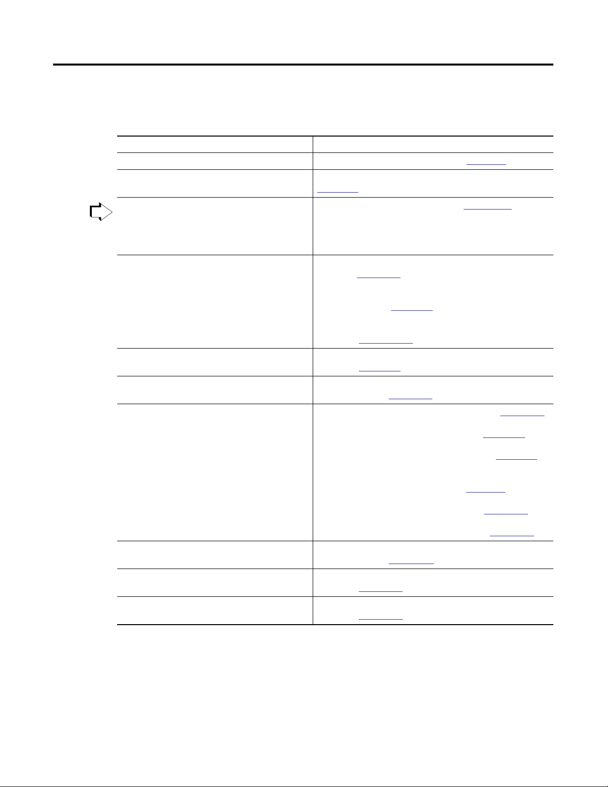
PhaseManager software lets you add equipment phases to your controller. An
equipment phase makes it easier to write, use, and manage the code for your
machine or equipment.
A PHASE tag gives you the status of an equipment phase.
An equipment phase directs 1 activity of your equipment.
A state model divides the activity into a set of states that have specific transitions.
Running State Routine
How to add
water
MainProgram
My_Equipment_Program
9Publication LOGIX-UM001B-EN-P - April 2010 9
Equipment phase instructions control the transitions between
states, handle faults, and so forth.
PSC POVR PCLF PRNP PATT
PCMD PFL PXRQ PPD PDET
Other code does the specific actions of your equipment
Water Feed
Conveyor Enable Axes
Page 10

Chapter 1 Introduction
PhaseManager Terms
Term Description
equipment phase An equipment phase is similar to a program:
state model A state model divides the operating cycle of your equipment into a set of states. Each state
state machine The controller has an embedded state machine for the equipment phase. This makes it a lot
• you run the equipment phase in a task.
• you give the equipment phase a set of routines and tags.
An equipment phase is different from a program in these ways:
• The equipment phase uses a state model.
• Use an equipment phase to do 1 activity of your equipment.
is an instant in the operation of the equipment. It's the actions or conditions of the
equipment at a given time.
The state model of an equipment phase is similar to these state models:
• U.S. standard ISA S88.01-1995 and its IEC equivalent IEC 61512-1-1998, commonly
referred to as S88
• PackML, which was previously under the supervision of OMAC but is now a working
group within ISA
easier to use the state model. The state machine:
• calls the main routine (state routine) for an acting state.
• manages the transitions between states with minimal coding.
You code the transition conditions. When the conditions are true, the state machine
transitions the equipment to the next required state.
• makes sure that the equipment goes from state to state along an allowable path.
For example, if the equipment is in the Complete or Stopped state, the equipment phase
makes sure that it goes only to the Resetting state. This simplifies the amount of
interlocking that you have to do.
equipment phase instructions Specific instructions that you use to control an equipment phase. See
PHASE tag When you add an equipment phase, RSLogix 5000 programming software makes a tag for
the equipment phase. The tag uses the PHASE data type. Use the tag to:
• see which state the equipment phase is in.
• hold a failure code for the equipment phase.
• hold an index for your steps.
• hold the unit ID.
• see the status of an external request to FactoryTalk Batch software.
• see if FactoryTalk Batch software has new parameters for the equipment phase.
• set up producing and standby states.
See
Appendix B
for more information about the PHASE data type.
Appendix A
.
PhaseManager software helps you write the code for your equipment in a
structured way. This results in the same behavior for all the equipment across a
plant.
10 Publication LOGIX-UM001B-EN-P - April 2010
Page 11

Introduction Chapter 1
PhaseManager Questions and Answers
Question Answer
How can I get the highest performance possible
from my equipment?
You have to measure equipment performance to improve it. The state model gives you a
way to measure the status of your equipment. With that data, you'll be able to calculate
the efficiency and performance measures that you want.
If you use PhaseManager software across your plant, you have consistent data from
equipment to equipment.
How can I cut the cost of integrating my
equipment into the plant?
Clear structure and consistent tags make it a lot easier to plug the equipment into your
plant and set up communication right away. Equipment up and down that line share
data using the same tag names. And all equipment communicates with higher-level
systems in the same way.
How can I make it easier to maintain the code? A state model helps you lay out the general functions of your equipment. We found that
the best programmers use a state model as the heart of their code. A state model serves
as a map for the code. With a clear structure, you'll know just where to look for the
piece of code that you want.
How can I give my operators a clean, intuitive
HMI?
A state model lets you make all your equipment behave the same. Your HMIs can then
show consistent equipment conditions across the plant. When an HMI says that the
equipment is idle, running, or holding, your operators will know exactly what that
means.
Publication LOGIX-UM001B-EN-P - April 2010 11
Page 12
Chapter 1 Introduction
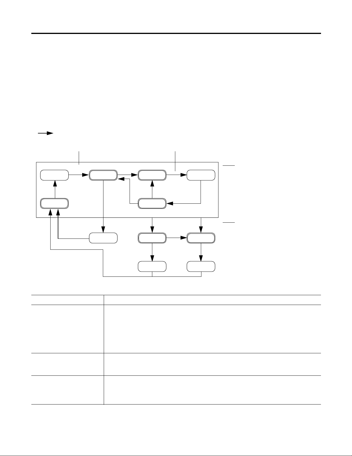
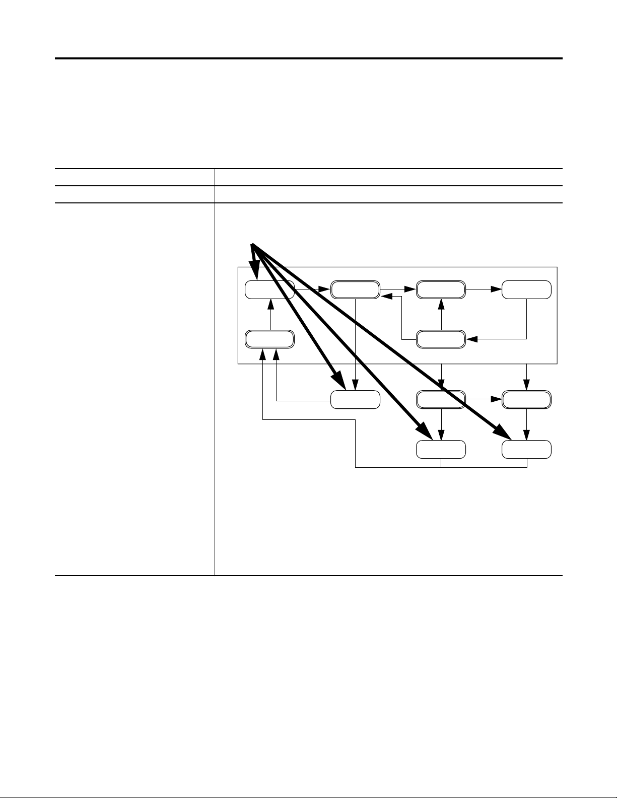
State Model Overview
Start
Idle
Running
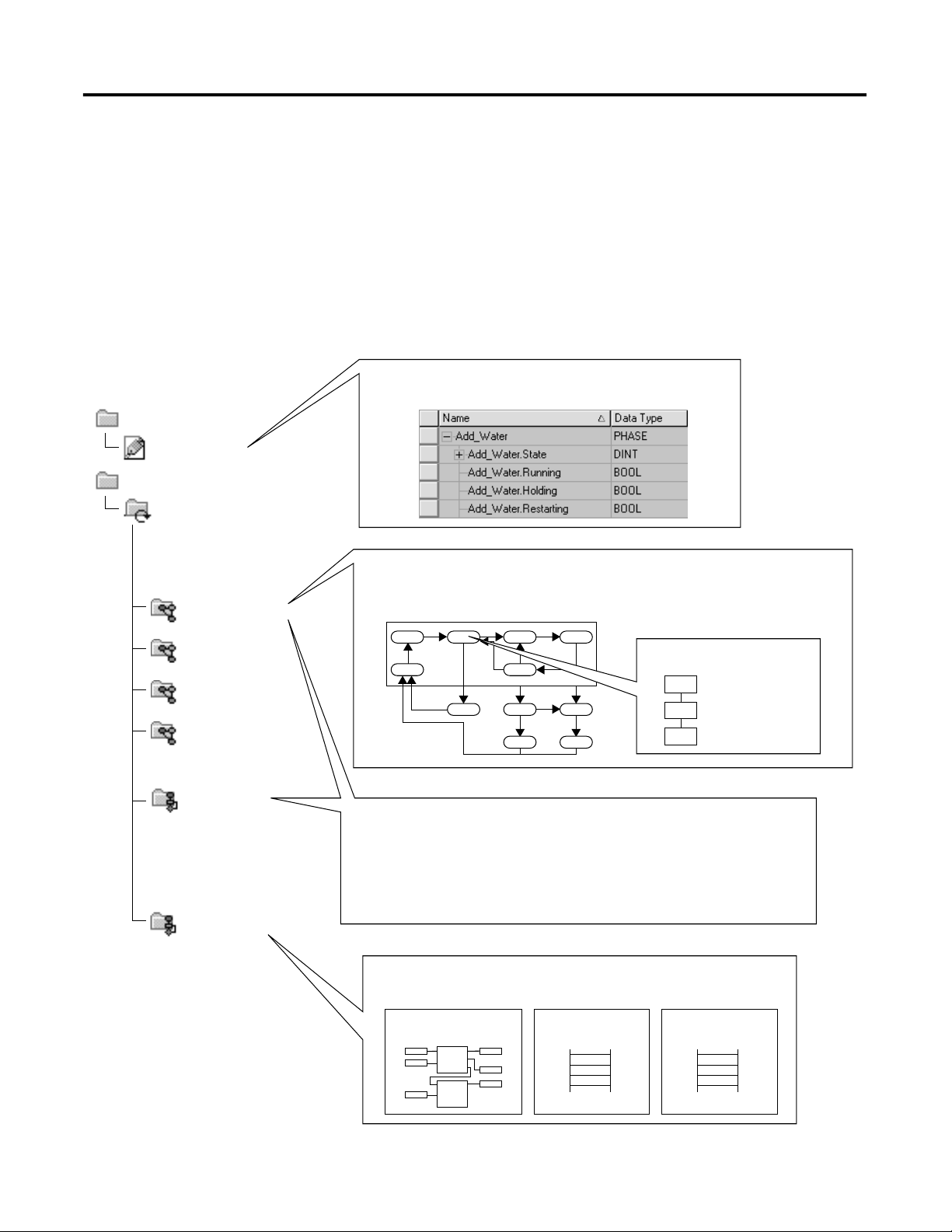
A state model divides the operating cycle of your equipment into a series of
states. Each state is an instant in the operation of the equipment. It's the
actions or conditions of the equipment at a given time.
In a state model, you define what your equipment does under different
conditions, such as run, hold, stop, and so forth. You don’t need to use all the
states for your equipment. Use only the states that you want.
There are two types of states.
Type of State Description
Acting Does something or several things for a certain time or until
certain conditions are met. An acting state runs one time or
repeatedly.
Waiting Shows that certain conditions are met and the equipment is
waiting for the signal to go to the next state.
PhaseManager software uses the following states.
Hold
Holding
Held
Your equipment can go from any
state in the box to the stopping or
aborting state.
Resetting
Reset
Complete
Reset
Hold
Restart
Restarting
Stop
Abort
Stopping
Stopped Aborted
Aborting
Abort
Acting
Acting states represent the
things your equipment does at
a given time.
Waiting
Waiting states represent the
condition of your equipment
when it is in-between acting
states.
12 Publication LOGIX-UM001B-EN-P - April 2010
Page 13

Introduction Chapter 1
One common objection to a state model is that it doesn't fit all equipment.
You may hear or think: ‘My equipment is very complex. There's a lot of
synchronization and many things happen in parallel.’
Keep in mind that a state model looks at your equipment at a very general
level. Different equipment does different things and needs specific code for
everything it does. A state model simply gives you a higher-level framework for
your code.
• The state model defines the general behavior, commands, and status of
the equipment.
• You program the details of the equipment within that framework.
Equipment States
The use of a state model may sound like a big change for programmers. But it's
simply a different way to look at the same control problem.
With a state model, you define the behavior of your equipment and put it into
a brief functional specification. In this way you show what happens and when
it happens.
For this State Ask
Stopped What happens when you turn on power?
Resetting How does the equipment get ready to run?
Idle How do you tell that the equipment is ready to run?
Running What does the equipment do to make product?
Holding How does the equipment temporarily stop making product without
making scrap?
Held How do you tell if the equipment is safely holding?
Restarting How does the equipment resume production after holding?
Complete How do you tell when the equipment is done with what it had to do?
Stopping What happens during an normal shutdown?
Aborting How does the equipment shutdown if a fault or failure happens?
Aborted How do you tell if the equipment is safely shutdown?
Publication LOGIX-UM001B-EN-P - April 2010 13
Page 14
Chapter 1 Introduction
State Transitions
= transition
Command Done — No command. Use PSC instruction instead.
Start
Idle
Resetting
Running
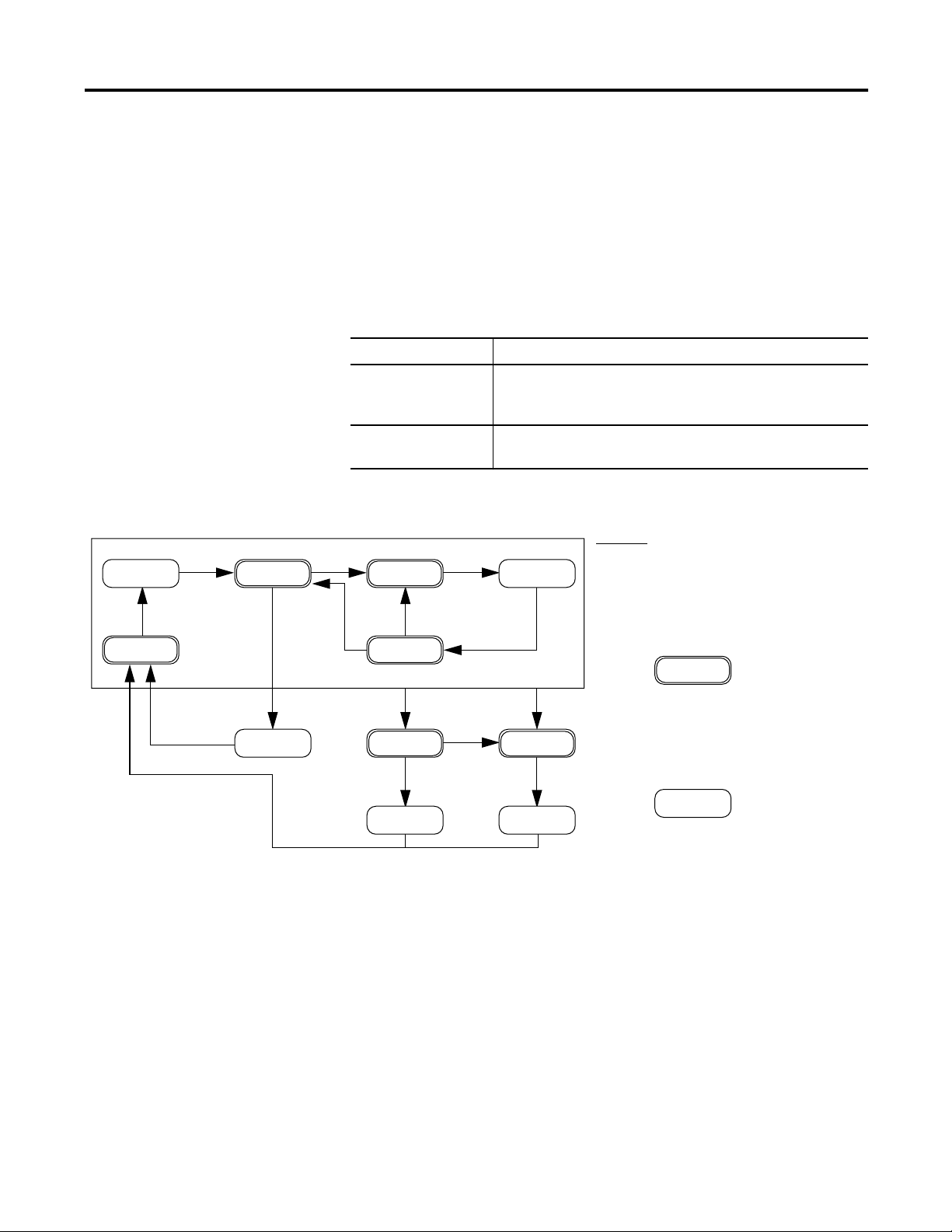
The arrows in the state model show to which states your equipment can go
from the state it is in now.
• Each arrow is called a transition.
• A state model lets the equipment make only certain transitions. This
gives the equipment the same behavior as any other equipment that uses
the same model.
PhaseManager software uses the following transitions.
Hold
Holding
Hold
Restarting
Held
Restart
Your equipment can go from any
state in the box to the stopping or
aborting state.
Stop
Reset
Complete
Reset
Type of Transition Description
Command A command tells the equipment to start doing something or do something different. For example the
operator pushes the start button to start production and the stop button to shutdown.
PhaseManager software uses these commands:
reset stop restart
start hold abort
Done Equipment goes to a waiting state when it's done with what it's doing. You don’t give the equipment a
command. Instead, you set up your code to signal when the equipment is done. The waiting state
shows that the equipment is done.
Fault A fault tells you that something out of the ordinary has happened. You set up your code to look for
faults and take action if it finds any. Suppose you want your equipment to shut down as fast as
possible if a certain fault happens. In that case, set up your code look for that fault and give the abort
command if it finds it.
Stopping
Stopped Aborted
Abort
Abort
Aborting
Fault (specific use of the abort
command)
14 Publication LOGIX-UM001B-EN-P - April 2010
Page 15
Introduction Chapter 1
Manually Change State
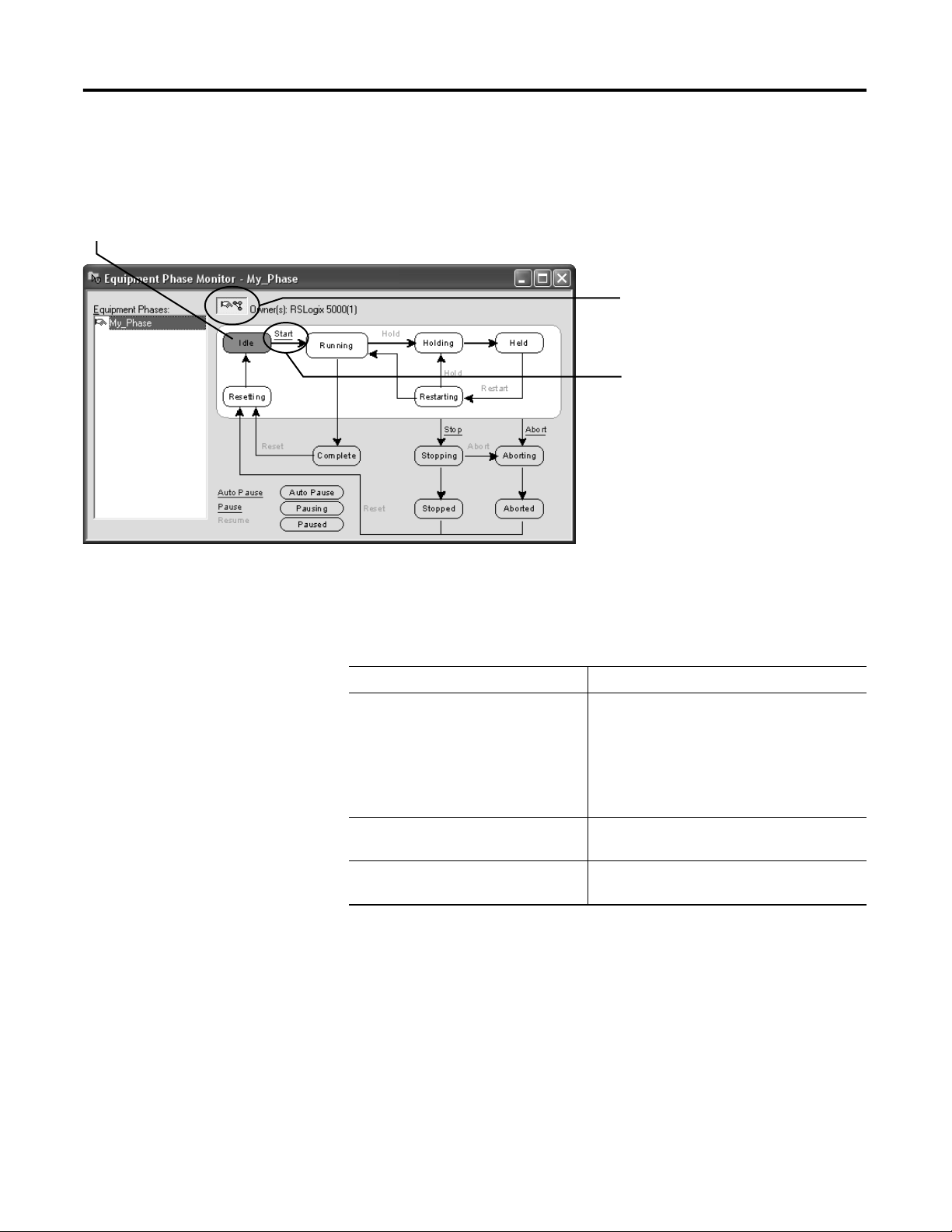
State that the equipment phase is in right now
RSLogix 5000 programming software has a window that lets you monitor and
command an equipment phase.
To manually change states.
1. Take ownership of the equipment phase.
2. Give a command.
Ownership
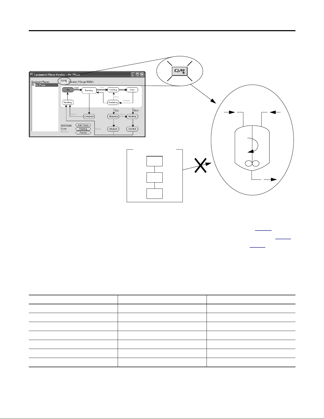
Ownership locks out programs or FactoryTalk Batch software from giving
commands to an equipment phase.
If this owns the equipment phase Then
RSLogix 5000 programming software Sequencers can’t give commands to the
equipment phase. This includes:
• Internal sequencer — program in the
controller.
• External sequencer — FactoryTalk Batch
software.
Internal sequencer — program in the
controller
External sequencer — FactoryTalk Batch
software
Other sequencers can’t give commands to the
equipment phase.
Other sequencers can’t give commands to the
equipment phase.
Exception: Use an Equipment Phase Override Command (POVR)
instruction to give a hold, stop, or abort command regardless of ownership.
Publication LOGIX-UM001B-EN-P - April 2010 15
Page 16
Chapter 1 Introduction
Takes ownership
My Code
Can’t command
See the following for additional information.
• Equipment Phase Command (PCMD) instruction on
page 62.
• Equipment Phase Override Command (POVR) instruction on
• Attach to Equipment Phase (PATT) instruction on
Comparison of Other State Models
S88 PackML PhaseManager Software
Idle Starting Ready Resetting Idle
Running Complete Producing Running Complete
Pausing Paused Standby subroutines, breakpoints, or both.
Holding Held Holding Held Holding Held
Restarting none Restarting
Stopping Stopped Stopping Stopped Stopping Stopped
Aborting Aborted Aborting Aborted Aborting Aborted
The following table compares PhaseManager software’s state model to other
common state models.
page 97
.
page 68
.
16 Publication LOGIX-UM001B-EN-P - April 2010
Page 17

PhaseManager Quick Start
Chapter 2
Purpose of This Chapter
Use this quick start to:
• get an introduction to how an equipment phase runs.
• monitor an equipment phase.
• manually tell an equipment phase to go to a different state.
Use this quick start when you want to:
• try out PhaseManager software for the first time.
• test an equipment phase by manually stepping through its states.
Topic Page
Create an Equipment Phase 18
Create a State Routine 18
Manually Step Through the States 19
Configure the Initial State for an Equipment Phase 22
Equipment
17Publication LOGIX-UM001B-EN-P - April 2010 17
To use this quick start, you need:
• a Logix5000 controller. See the preface if you aren’t sure which
controllers are Logix5000 controllers.
• firmware, revision 18.0 or later, for the controller
• a power supply for the controller
• a communication path to the controller:
– Communication card or built-in port
– Corresponding communication cable
• RSLogix 5000 programming software, version 18.0 or later
Page 18
Chapter 2 PhaseManager Quick Start
2
3
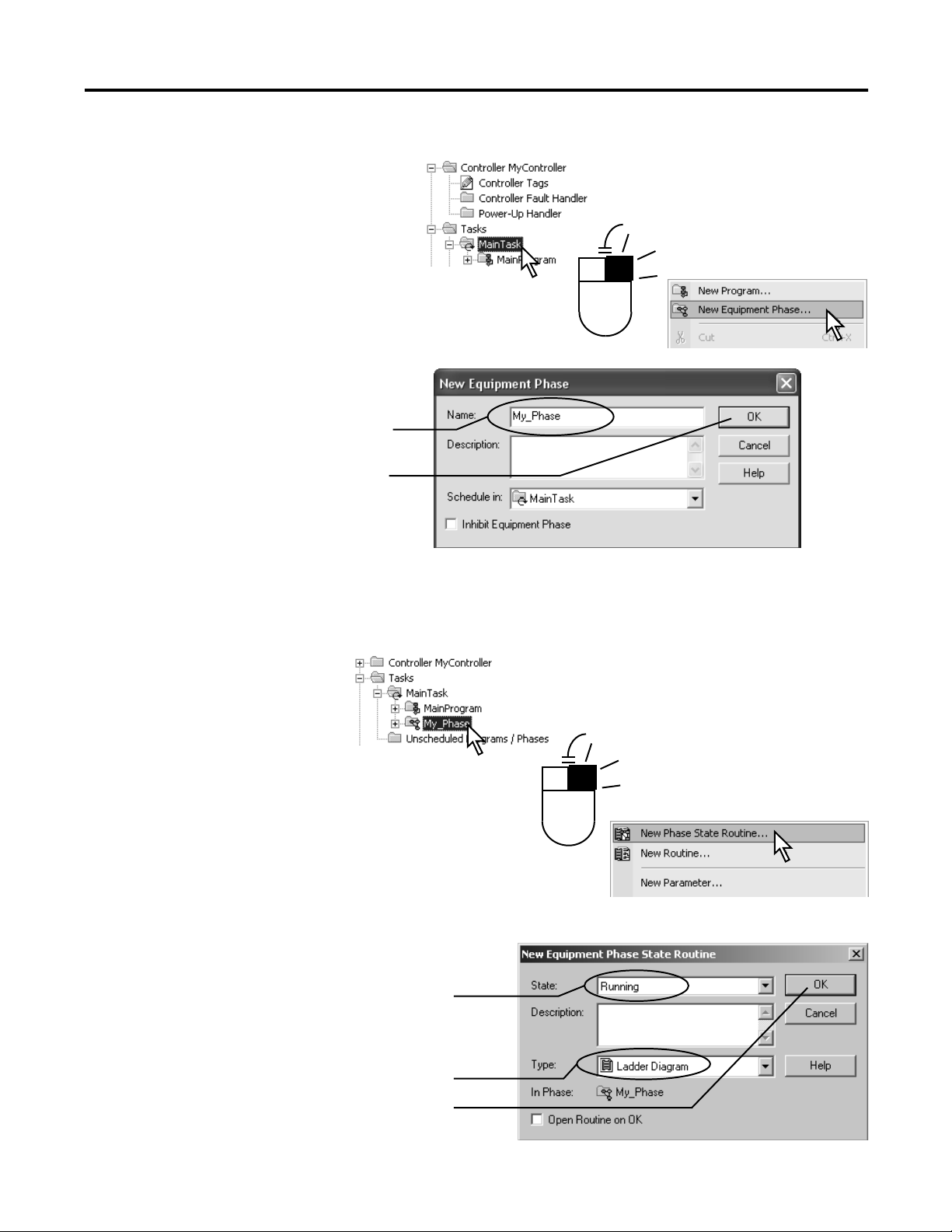
Create an Equipment Phase
1.
.
.
Create a State Routine
1.
2.
3.
18 Publication LOGIX-UM001B-EN-P - April 2010
4.
Page 19
PhaseManager Quick Start Chapter 2
Manually Step Through the States
Step Notes
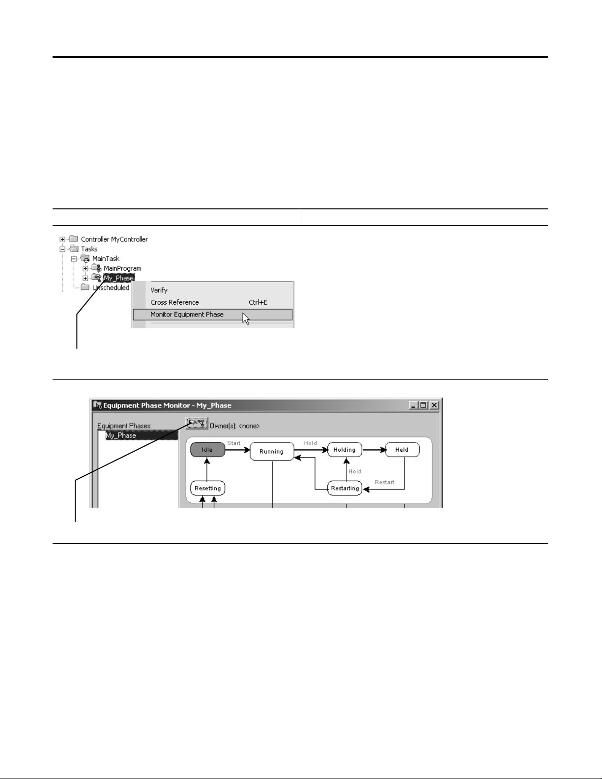
1. Right-click the equipment phase and choose Monitor Equipment
Phase.
Before you do this procedure, do the following:
• Download the project to the controller.
• Put the controller in run or remote run mode.
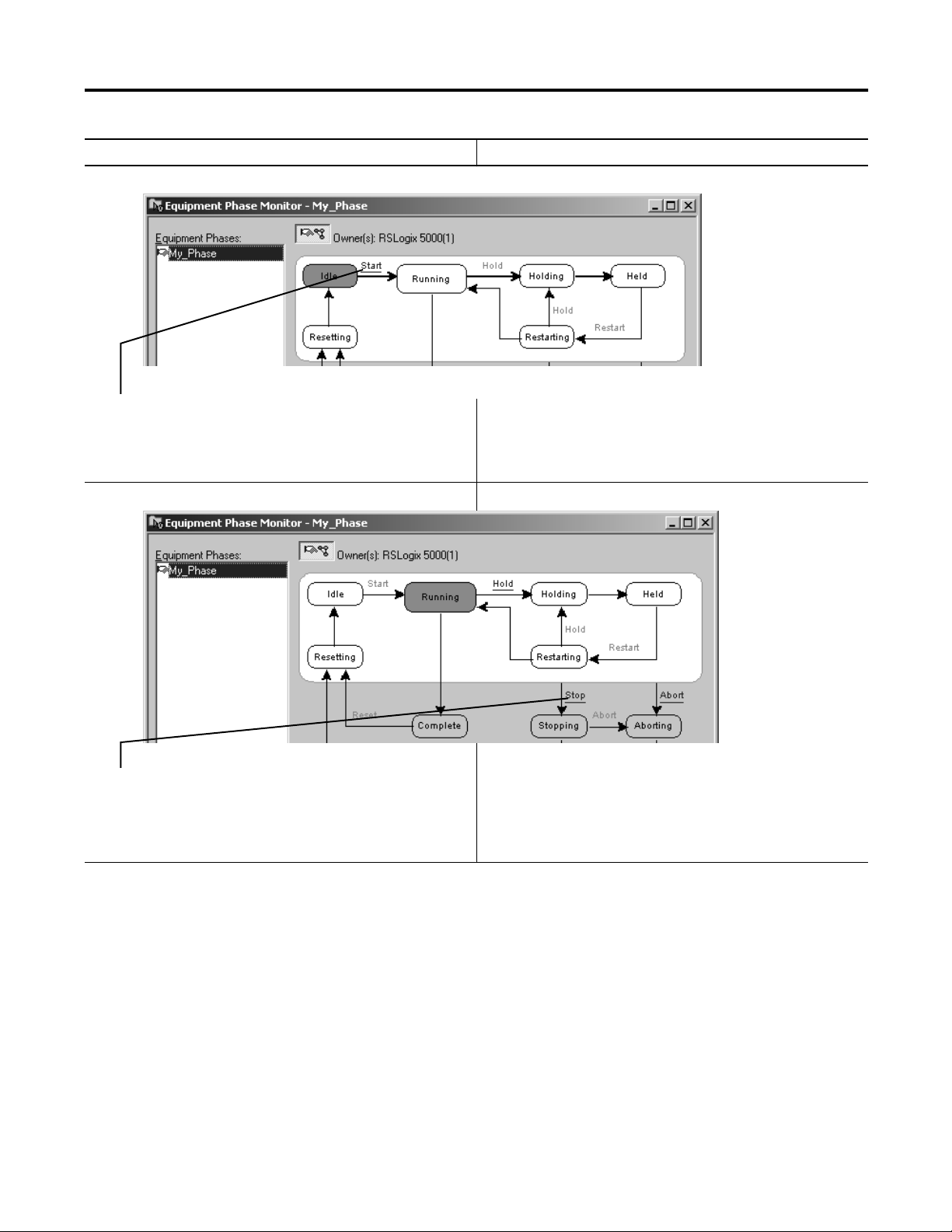
2. Click the ownership button and then Yes—take ownership. This lets you use this window to step through the states.
Publication LOGIX-UM001B-EN-P - April 2010 19
Page 20
Chapter 2 PhaseManager Quick Start
Step Notes
3. Click Start. • The equipment phase goes to the Running state.
• Any code in the Running state routine starts running. This is
where you put the code for the normal production sequence of
your equipment.
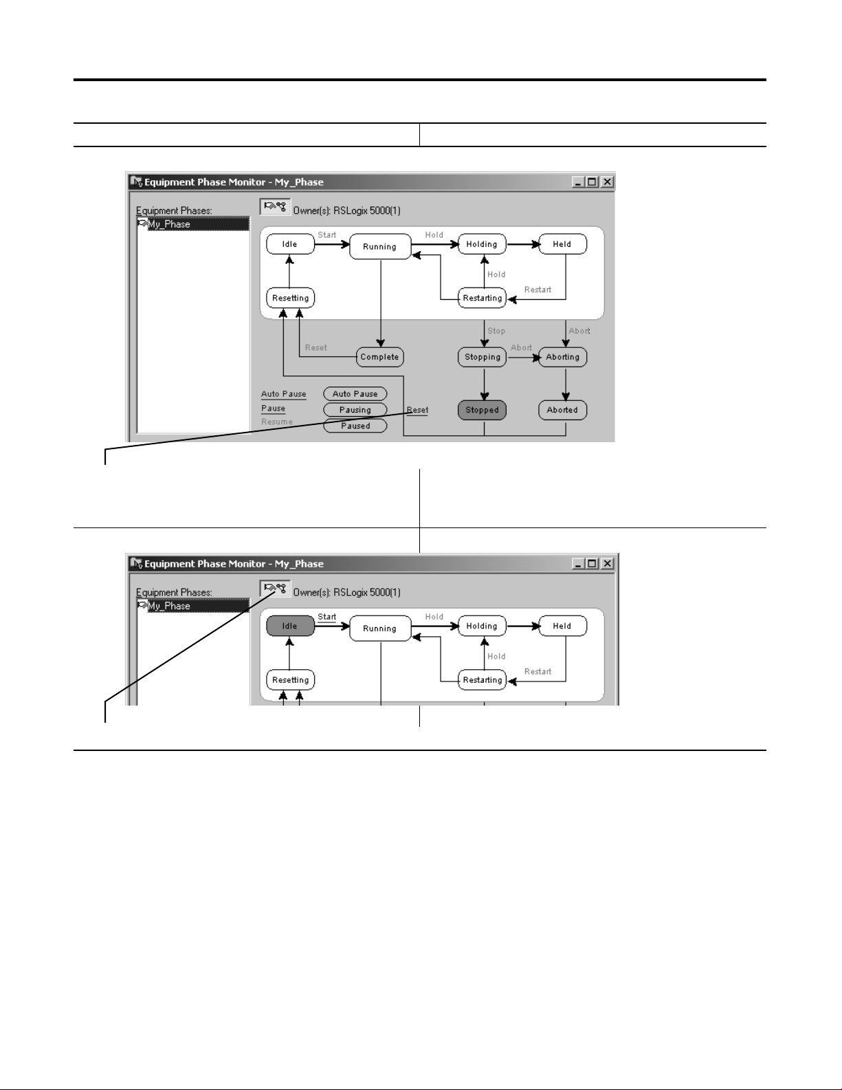
4. Click Stop. • The equipment phase goes to the Stopped state.
• The Running state routine stops running.
• The Stopping state routine is optional. Without it, the
equipment phase goes directly to the Stopped state.
20 Publication LOGIX-UM001B-EN-P - April 2010
Page 21
Step Notes
PhaseManager Quick Start Chapter 2
5. Click Reset. • The equipment phase goes to the Idle state.
• The Resetting state routine is optional. Without it, the
equipment phase goes directly to the Idle state.
6. Click the ownership button. This releases the equipment phase from control by this window.
Publication LOGIX-UM001B-EN-P - April 2010 21
Page 22
Chapter 2 PhaseManager Quick Start
3
4
2
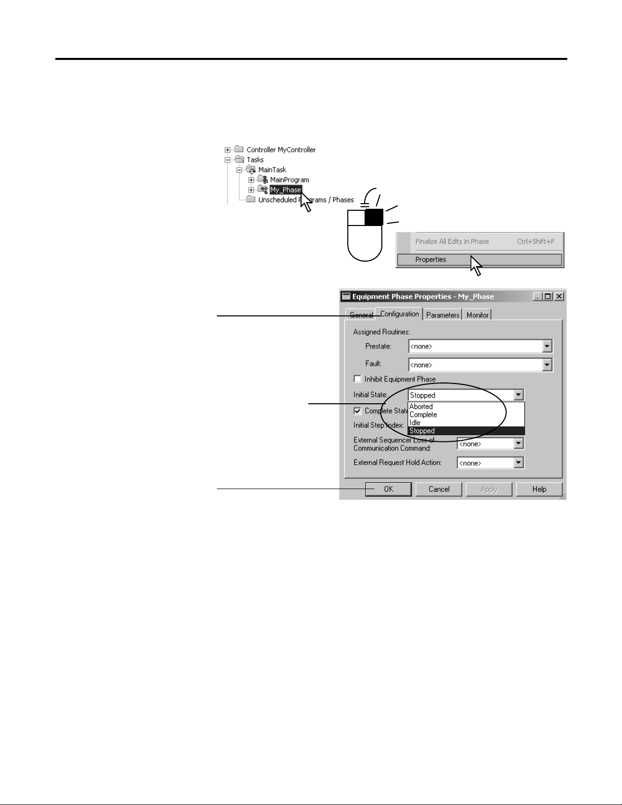
Configure the Initial State for an Equipment Phase
1.
.
The initial state is the first state to which the equipment phase goes after
power up.
. Choose your initial state.
.
22 Publication LOGIX-UM001B-EN-P - April 2010
Page 23

Guidelines
Chapter 3
Purpose of this chapter
To guide your development and programming of a Logix5000 project that
uses equipment phases
Use this chapter:
• before you lay-out the equipment phases for your Logix5000 project.
• as a reference while you program the project.
Review the following guidelines before you lay-out your project and refer back
to them as needed:
Topic Page
Equipment Model Guidelines 24
State Model Guidelines 26
Equipment Code Guidelines 31
Execution Guidelines 34
State Completion Guidelines 46
Transition Guidelines 40
Equipment Interface Tag Guidelines 48
Alias Tag Guidelines 53
23Publication LOGIX-UM001B-EN-P - April 2010 23
Page 24

Chapter 3 Guidelines
Equipment Model
Each equipment phase is a specific activity that your equipment does. An
equipment phase tells the equipment what to do and when to do it.
Guidelines
Follow these guidelines to decide how many equipment phases to use.
Guideline Details
Make sure each equipment phase does
an independent activity.
Keep the number of equipment phases
and programs within the following limits.
List the equipment that goes along with
each equipment phase.
Make sure each equipment phase does an activity that is independent (relatively
independent) from other equipment. The equipment phase commands all the equipment that
works together to do the specific activity.
Example
This is probably an equipment
phase
• Fill bottles with product.
• Put bottles in carton.
• Add water to a tank.
• Mix ingredients in tank
If you have this controller You can have up to
ControlLogix 100 programs and equipment phases per task
SoftLogix 100 programs and equipment phases per task
FlexLogix 32 programs and equipment phases per task
CompactLogix 32 programs and equipment phases per task
Example
This equipment phase Relates this equipment
Add_Water water pump
Smart_Belt Coarse belt axis
This in probably NOT an equipment phase
• Accelerate filler axis (too small)
• Run bottling line (too big)
• Open water valve (too small)
• Brew ingredients (too big)
water valve
limit switch
Fine belt axis
Exit belt axis
24 Publication LOGIX-UM001B-EN-P - April 2010
Page 25
tank completes these steps.
1. Adds water.
2. Heats the water.
3. Adds other ingredients.
4. Mixes all the ingredients.
5. Dispenses the finished
product.
Guidelines Chapter 3
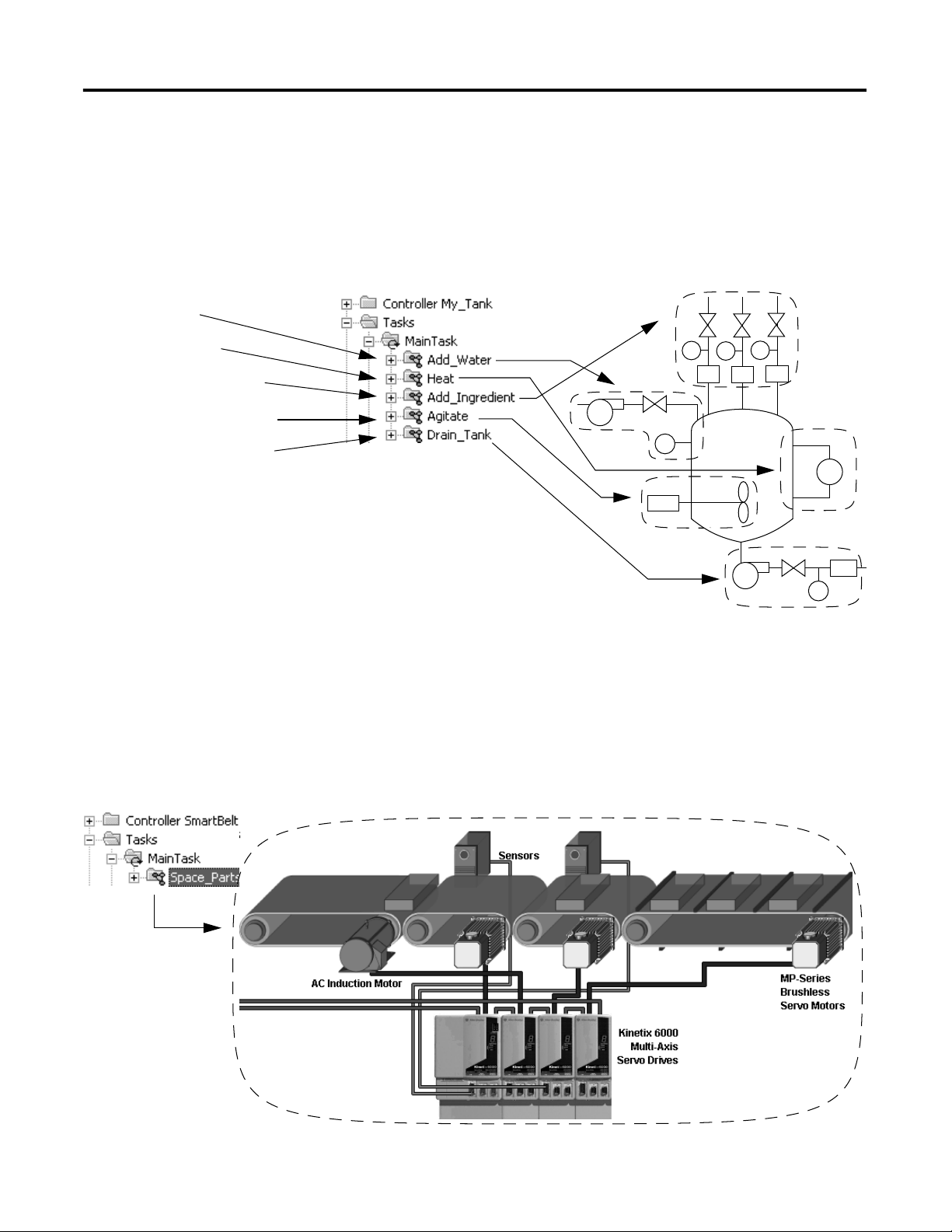
Example 1: Tank
The following example shows the equipment phases for a tank that cooks
ingredients.
Which become these phases Which commands this equipmentTo cook the ingredients, the
Example 2: Smart Belt
The following example shows a smart belt. The smart belt does only one
activity. It spaces product evenly on an exit belt. Because it does only one
activity, it needs only 1 equipment phase.
Publication LOGIX-UM001B-EN-P - April 2010 25
Page 26
Chapter 3 Guidelines
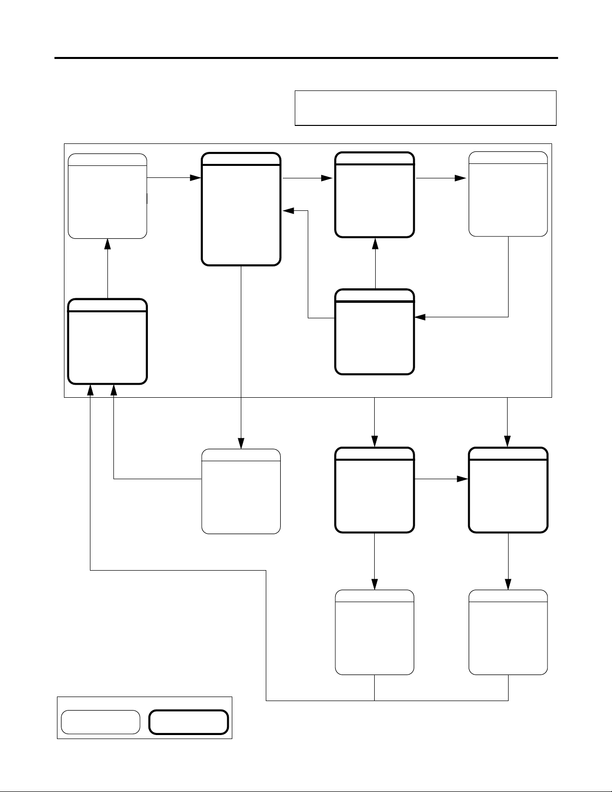
State Model Guidelines
A state model divides the operating cycle of your equipment into a series of
states. Each state is an instant in the operation of the equipment. It's the
actions or conditions of the equipment at a given time.
Follow these guidelines as you fill out the state model for an equipment phase.
Guideline Details
Fill out 1 state model for each phase. Each phase runs its own set of states. Fill out 1 state model worksheet for each phase.
Decide which state you want as your
initial state after power-up.
Which state do you want the equipment phase to go to when you turn on power?
ON
?
Idle
Resetting
Start
Running
Reset
Complete
Hold
Holding
Hold
Restarting
Stop
Stopping
Restart
Abort
Aborting
Held
Abort
Reset
An equipment phase goes to its initial state when you turn on power. We recommend that you
use one of these states as the initial state:
• Idle (default)
• Complete
• Stopped
Choose the initial state that best shows what your equipment is waiting to do after power-up
(reset, run, and so forth).
Stopped Aborted
26 Publication LOGIX-UM001B-EN-P - April 2010
Page 27

Guidelines Chapter 3
Guideline Details
Start with the initial state and work
through the model.
Start with the initial state. Then work forward from that point. Use the following questions to
help you.
For this State Ask
Stopped What happens when you turn on power?
Resetting How does the equipment get ready to run?
Idle How do you tell that the equipment is ready to run?
Running What does the equipment do to make product?
Holding How does the equipment pause without making scrap?
Held How do you tell if the equipment is safely paused?
Restarting How does the equipment resume production after a pause?
Complete How do you tell when the equipment is done with what it had to do?
Stopping What happens during an normal shutdown?
Aborting How does the equipment shutdown if a fault or failure happens?
Aborted How do you tell if the equipment is safely shutdown?
Use only the states that you want. Define only the states that are appropriate for your equipment. You don’t need to use all the
states. The equipment phase just skips any states that you don’t add.
For the producing and standby states, use
subroutines.
If you want to define producing and standby states for your equipment, use subroutines.
A. Create a routines for the producing state and another routine for the standby state.
B. In the running state, check for the produce verses standby conditions. Set either the
Producing bit or the Standby bit of the equipment phase tag.
C. Use the Producing and Standby bits as conditions to call the corresponding routine.
See
Appendix B
.
Publication LOGIX-UM001B-EN-P - April 2010 27
Page 28
Chapter 3 Guidelines
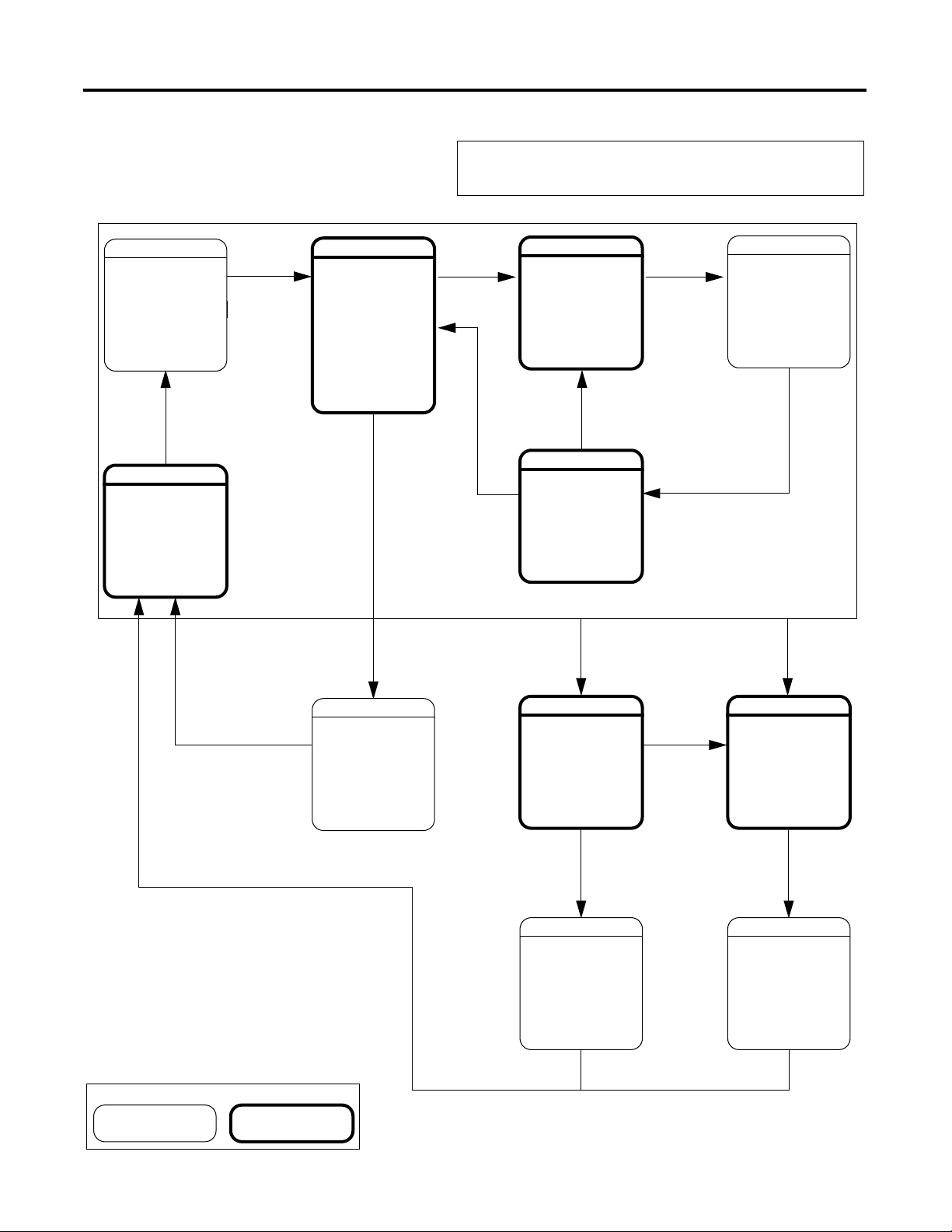
State Model Worksheet
IDLE
To
Done
RESETTING
Start
Command
RUNNING
Done
Equipment Phase:
Hold
Command
Done
HOLDING
RESTARTING
Done
HELD
Hold
Command
Restart
Command
Reset
Command
COMPLETE
Reset
Command
Command
STOPPING
Done
STOPPED
Stop
Abort
Command
Abort
Command
ABORTING
Done
ABORTED
Key
Waiting State Acting State
28 Publication LOGIX-UM001B-EN-P - April 2010
Page 29
Guidelines Chapter 3
Example 1: Add Water
IDLE
· No water flow
· Tank Not full
· Operator can
control equipment
To
Done
RESETTING
Command
Start
RUNNING
· Lock equipment in
program control
· Add water
· Unlock equipment
from program
control
Done
Equipment Phase: Add Water
Hold
Command
Done
HOLDING
· Stop water
· Unlock equipment
from program
control
Hold
Command
RESTARTING
· Lock equipment in
program control
Done
HELD
· No water flow
· Operator can
control equipment
Restart
Command
Reset
Command
COMPLETE
· No water flow
· Water at high limit
· Operator can
control equipment
Reset
Command
Stop
Command
STOPPING
· Stop water
· Unlock equipment
from program
control
Done
STOPPED
· No water flow
· Operator can
control equipment
Abort
Command
Abort
Command
ABORTING
· Stop water
· Unlock equipment
from program
control
Done
ABORTED
· No water flow
· Operator can
control equipment
Key
Waiting State Acting State
Publication LOGIX-UM001B-EN-P - April 2010 29
Page 30

Chapter 3 Guidelines
Example 2: Space Parts
IDLE
· No axes faults
· All axes = on
· Exit belt = homed
· Registration =
armed
· Clear axes faults
· Turn on all axes
· Home exit belt
· Arm registration
To
Done
RESETTING
Start
Command
RUNNING
· Jog exit belt
· Gear other belts
· Put 1 box on fine
belt
· Put 1 box on each
flight
Done
Equipment Phase: Space Parts
Hold
Command
Done
HOLDING
· Set speed of exit
belt = 0
Hold
Command
RESTARTING
· Jog exit belt
Done
HELD
· Speed of exit belt
=0
Restart
Command
Reset
Command
COMPLETE
Not used
Reset
Command
Stop
Command
STOPPING
· Run out boxes on
coarse belt
· Stop coarse and
fine belts
· Empty exit belt
· Stop exit belt
Done
STOPPED
· All axes = off
· SERCOS = phased
up
· All network
connections are
made
Abort
Command
Abort
Command
ABORTING
· Turn off all axes
Done
ABORTED
· All axes = off
· Boxes may still be
on belts
Key
Waiting State Acting State
30 Publication LOGIX-UM001B-EN-P - April 2010
Page 31

Guidelines Chapter 3
Equipment Code Guidelines
Step 1
Step 2
Step 3
Step 4
To start the equipment, the equipment
phase gives the equipment program a start
command, a set point, and so forth.
The equipment program sends back
information such as current state, total, and
so forth.
One advantage of an equipment phase is that it lets you separate the
procedures (recipes) for how to make the product from the control of the
equipment that makes the product. This makes it much easier to execute
different procedures for different products using the same equipment.
Equipment Phase
Directs the actions of the
equipment (what to do and
when)
• produce product
• stop producing product
• add water to a tank
• wait for the operator to do
Equipment Program
Does the actions for a specific
group of devices (does it)
• jog axis
• run pump
• open valve
• calculate control variable
Step 5
Step 6
The equipment program controls the
equipment.
Publication LOGIX-UM001B-EN-P - April 2010 31
Page 32

Chapter 3 Guidelines
Example 1: Add Water to a Tank
The equipment phase tells the equipment program to go to
program mode and add water.
The equipment program follows the commands of the equipment
phase and sends back its mode and state.
32 Publication LOGIX-UM001B-EN-P - April 2010
Page 33

Example 2: Smart Belt
The equipment phase tells the equipment program to reset faults. The
equipment phase then waits for the equipment program to turn on a done
bit. When the done bit turns on, the equipment phase clears the command
to reset faults. The equipment phase then goes to the next step in the
sequence.
Guidelines Chapter 3
The equipment program resets faults when it gets the fault reset command
from the equipment phase. It turns on a done bit after it clears the faults.
Publication LOGIX-UM001B-EN-P - April 2010 33
Page 34

Chapter 3 Guidelines
Execution Guidelines
Use the resetting, running, and stopping states
for the normal execution of the equipment.
A state model makes it much easier to separate the normal execution of your
equipment from any exceptions (faults, failures, off-normal conditions).
Use the holding, restarting, and aborting states to
handle exceptions (faults, failures, off-normal
conditions).
HoldingIdle Running Held
Resetting
Complete
Restarting
Stopping Aborting
Stopped Aborted
Guideline Details
Use the prestate routine to watch for
faults
Use the prestate routine for conditions that you want to watch all the time such as fault bits.
The prestate routine:
• runs all the time.
• runs before each scan of a state.
• runs even in the waiting states (idle, held, complete, stopped, or aborted).
prestate routine
current state
routine
34 Publication LOGIX-UM001B-EN-P - April 2010
Page 35

Guideline Details
Create a prestate routine just like the
routine for a program. It’s not a phase
state routine.
1.
2.
Guidelines Chapter 3
3. Choose any language.
4.
Publication LOGIX-UM001B-EN-P - April 2010 35
Page 36

Chapter 3 Guidelines
3
4
2
Guideline Details
Assign a prestate routine.
1.
.
.
.
Use a state bit to limit code to a specific
state
RSLogix 5000 software automatically makes a tag for each equipment phase. The tag has bits
that tell you the state of the equipment phase.
• The tag is at the controller scope.
• The tag uses the PHASE data type.
• Use bits of the tag for code that you want to limit to certain states.
Example
Suppose the name of your equipment phase is My_Phase. And you have some code that you
want to run only when the equipment phase is in the running state. In that case, check the
My_Phase.Running bit for on (1):
If My_Phase.Running then…
See
Appendix B
for more information.
36 Publication LOGIX-UM001B-EN-P - April 2010
Page 37

Guidelines Chapter 3
Guideline Details
Use the empty phase state routine to
complete phase execution
Unlike normal program routines, phase state routines are called by the batch manager (not
other program routines(, so they always have the potential of being called.
In the configuration for a phase state routine, if the Complete State Immediately if not
Implemented option is checked in RSLogix 5000 programming software, version 18 or later, an
implemented, but empty (no logic), phase state routine behaves the same as an implemented
phase state routine. The state immediately completes and execution of the phase continues.
The phase then enters the next state in the state machine.
In RSLogix 5000 programming software, version 16 and earlier, if a phase enters a state for
which a state routine exists, but contains no logic, execution of the phase stops. The routine
does complete, but there is no logic to execute.
Choose from the following if you import a new state routine and in the Online Options dialog
box.
• Import Logic Edits as Pending, an empty routine is created in the controller and the
pending edits exist in the offline project.
• Accepts Program Edits, an empty routine is created in the controller and the logic is placed
in a test edits container in the routine. If you are not actively testing edits, then the routine
appears as empty when running.
• Finalize All Edits in Program, the routine is created with the new logic and does not appear
empty.
In the first two cases, if the Complete State Immediately if not Implemented option is
checked, the empty routine will complete immediately and allow phase execution to continue.
Use the PFL instruction to signal a fault The Equipment Phase Failure (PFL) instruction sets a failure code for an equipment phase. Use
the code to signal a specific failure such as the fault of a specific device.
• The PFL instruction writes a code to the failure member for the equipment phase.
• To see the failure code of an equipment phase, look at the phase_name.Failure tag.
• The failure code stays until any of the following happens:
• A PFL instruction sets the failure code to a larger number.
• The equipment phase transitions from the resetting state idle state.
• A PCLF instruction clears the failure code.
• FactoryTalk Batch software clears the failure code.
See
page 72
for more information.
Use a PCLF instruction to clear a failure
code
The Equipment Phase Clear Failure (PCLF) instruction clears the failure code for an equipment
phase.
• A CLR instruction, MOV instruction, or assignment (:=) d doesn’t change the failure code of
an equipment phase.
• If you are testing a PCLF instruction, make sure RSLogix 5000 software doesn’t own the
equipment phase. The PCLF instruction doesn’t work if RSLogix 5000 software owns the
equipment phase.
See
page 76
for more information.
Publication LOGIX-UM001B-EN-P - April 2010 37
Page 38

Chapter 3 Guidelines
Example 1: Add Water to a Tank
The prestate routine watches for equipment faults while the equipment phase is in
the running state (Add_Water.Running = 1). If Water_Feed.Health = 1, then a fault
happened. If a fault happens, the equipment phase sets a failure code of 202.
If Add_Water.Running And Water_Feed.Health Then
PFL(202);
End_If;
The equipment program watches the fault bits of the valve, pump, and their feedback devices.
If any of that equipment faults, the equipment program turns on the Water_Feed.Health bit.
38 Publication LOGIX-UM001B-EN-P - April 2010
Page 39

Example 2: Smart Belt
Guidelines Chapter 3
The preset value of this step = 20000 ms. The step
turns on its DN bit if it doesn’t clear the faults
within 20000 ms.
If Step_000.DN = on, a timeout happened. When a timeout happens, the OSR instruction
turns on the Clear_Faults_Timeout bit for one scan.
If MyPhase is in the resetting state and Clear_Faults_Timeout is on, then the PFL instruction
signals a failure. The PFL instruction sets the failure code = 501.
Publication LOGIX-UM001B-EN-P - April 2010 39
Page 40

Chapter 3 Guidelines
Transition Guidelines
To start an acting state, you usually have to give the equipment phase a
command. The command tells the equipment phase and its equipment to start
doing something or do something different. Use the Equipment Phase
Command (PCMD) instruction to give a command to an equipment phase.
Optional: You can also use FactoryTalk Batch software in place of a PCMD
instruction to trigger transitions
Use the state model to see which transitions need a PCMD instruction.
Idle
Resetting
PCMD instruction
Start
Reset
Running
done donedone
Complete
Hold
Restarting
Stopping
Holding
PSC instruction
done
Hold
Restart
Stop
Abort
Held
Abort
Aborting
Reset
Type of Transition Description Instruction
Command A command tells the equipment to start doing something or do something
different. For example the operator pushes the start button to start production
and the stop button to shutdown.
PhaseManager software Software Software uses these commands:
reset stop restart
start hold abort
Done Equipment goes to a waiting state when it's done with what it's doing. You
set up your code to signal when the equipment is done. The waiting state
shows that the equipment is done.
Exception: The restarting state goes to the running state when it’s done.
Stopped Aborted
PCMD
Use an Equipment Phase
Command (PCMD) instruction
to give a command. Or use
RSLogix 5000 software.
See
page 62
information.
PSC
Use the Phase State Complete
(PSC) instruction to signal
when a state is done. See
page 59
for more information.
donedone
for more
40 Publication LOGIX-UM001B-EN-P - April 2010
Page 41

Guideline Details
A PCMD instruction causes a transition
right away.
A PCMD instruction makes an equipment phase go to the commanded state. The equipment
phase changes states as soon as it finishes its current scan. This happens even if the current
state isn’t done.
See if you need to reset the state that
you’ve left.
Are you leaving an acting state (for example, running, holding)?
• YES — Consider resetting the code of the state that you’ve left.
• NO — You probably don’t need to reset anything.
The equipment phase stops running the code of the current state when it goes to a different
state. This leaves outputs at their last values unless the new state takes control of them. It
also leaves an SFC at the step it was at when the equipment phase changed states.
Example 1: You don’t need to reset
Suppose your equipment phase is in the idle state. In that case, it isn’t running any state code.
So you probably don’t need to reset any state when you go to a different state like running,
stopping, and so forth.
Example 2: You don’t need to reset
Suppose your equipment phase is in the running state and you go to the holding state. When
you go back to the running state, you probably want to pick up where you left off. In that case,
you probably don’t need to reset the code in the running state.
Guidelines Chapter 3
Use an SFR instruction to reset the SFC of
a state routine.
Use the PCMD instruction to go to an
allowed next state.
Example 3: You must reset
Suppose your equipment phase is half way through the resetting state and you give the stop
command. And suppose you want to run the entire resetting sequence when you go back to it.
In that case, you probably need to reset the code of the resetting state. If the resetting state
uses an SFC, then use the SFR instruction to reset it to the first step.
An SFC Reset (SFR) instruction is one way to reset an SFC. In some cases, reset an SFC from
several other state routines.
To reset the SFC of this
Place an SFR instruction in this state routine
state
Running Resetting
Holding Holding—Let the SFC reset itself at the last step.
Restarting Reset the restarting routine in both these routines:
• Holding—In case you go back to holding before you finish
restarting.
• Restarting—Let the SFC reset itself at the last step.
PhaseManager software makes sure that an equipment phase follows the state model. So the
equipment phase goes only to certain states from the state that it is in right now.
Example 1: A transition is allowed
Suppose your equipment phase is in the running state and you give it the hold command. In
that case, the equipment phase goes to holding because that transition is allowed.
Example 2: A transition isn’t allowed
Suppose your equipment phase is in the running state and you give it the reset command. In
that case, the equipment phase stays in the running state. To go to the resetting state, you
first have to stop or abort the equipment phase.
Publication LOGIX-UM001B-EN-P - April 2010 41
Page 42

Chapter 3 Guidelines
Guideline Details
See if you must use a POVR instruction
instead of a PCMD instruction.
Takes ownership
My Code
Can’t command
A. Are you giving the hold, stop, or abort command?
· NO — Use the PCMD instruction.
· YES — Go to step B.
B. Must the command work even if you have manual control of the equipment phase via
RSLogix 5000 software?
· YES — Use the POVR instruction instead. See
page 68
.
· NO — Go to step C.
C. Must the command work even if FactoryTalk Batch software or another program owns the
equipment phase?
· YES — Use the POVR instruction instead. See
page 68
.
· NO — Use the PCMD instruction.
42 Publication LOGIX-UM001B-EN-P - April 2010
Page 43

Guidelines Chapter 3
Example 1: Tank
The controller uses an SFC to command the phases that run the tank (add water,
heat, add ingredients, and so forth).
Give the start command to the Add_Water equipment
phase. The P1 qualifier limits this to the first scan of
the step.
Wait until the Add_Water equipment phase
is done (complete). When the equipment
phase is done, give the reset command. The
P0 qualifier limits this to the last scan of the
step.
Start the next equipment phase.
Publication LOGIX-UM001B-EN-P - April 2010 43
Page 44

Chapter 3 Guidelines
Example 2: Smart Belt
If the operator presses the start button on the machine or HMI, then
My_Inputs.AnyStartPressed = on for 1 scan.
The ONS instruction makes sure that My_Inputs.AnyStartPressed turns on only
when a start button goes from off on.
If the equipment phase is in the idle state and My_Inputs.AnyStartPressed = on, then
The PCMD instruction gives MyPhase the start command.
44 Publication LOGIX-UM001B-EN-P - April 2010
Page 45

Guidelines Chapter 3
Example 3: Jam Detection
The equipment program watches for the following faults:
• Faulted axis
• Jammed material
If there is a fault, then
Local_Interface.Equipment_Faults_Cleared = 0. This tag is an alias for the
controller-scoped tag Shear_1.
The prestate routine of the equipment phase watches for the equipment program to signal a
fault.
• If Interface_To_Equipment.Equipment_Faults_Cleared = 0 then there is a fault.
• Both Interface_To_Equipment and Local_Interface are aliases for Shear_1, so they have
the same values.
If there is a fault Then
Give the Shear_One_Phase equipment phase the abort command. The POVR instruction
makes sure the command works even if someone has manual control of the equipment
phase through RSLogix 5000 software.
The PFL instruction sets the failure code for Shear_One_Phase = 333.
The Fault_Strobe keeps these actions to a single scan.
Publication LOGIX-UM001B-EN-P - April 2010 45
Page 46

Chapter 3 Guidelines
State Completion Guidelines
IMPORTANT
To leave an acting state, you usually signal that the state is done doing what it
had to do. Use the Phase State Complete (PSC) instruction to signal when a
state is done.
The PSC instruction doesn’t stop the current scan of a routine.
When the PSC instruction executes, the controller scans the rest of the routine and
then transitions the equipment phase to the next state. The PSC instruction does not
terminate the execution of the routine.
Use the state model to see which transitions need a PSC instruction.
Idle
Resetting
PCMD instruction
Start
Hold
Running
done donedone
Restarting
Holding
PSC instruction
done
Held
Hold
Restart
Stop
Reset
Complete
Reset
Type of transition Description Instruction
Command A command tells the equipment to start doing something or do something
different. For example the operator pushes the start button to start production
and the stop button to shutdown.
PhaseManager software Software uses these commands:
reset stop restart
start hold abort
Done Equipment goes to a waiting state when it's done with what it's doing. You
set up your code to signal when the equipment is done. The waiting state
shows that the equipment is done.
Exception: The restarting state goes to the running state when it’s done.
Stopping
Stopped Aborted
Abort
PCMD
Use an Equipment Phase
Command (PCMD) instruction
to give a command. Or use
RSLogix 5000 software.
PSC
Use the Phase State Complete
(PSC) instruction to signal
when a state is done. See
page 59
for more information.
Abort
Aborting
donedone
46 Publication LOGIX-UM001B-EN-P - April 2010
Page 47

Example 1: Add Water to a Tank
The holding state does three things.
1. Rung 0 — stop the water.
2. Rung 1 — unlock the devices from program control.
3. Rung 2 — signal that the state is done.
Guidelines Chapter 3
Example 2: Smart Belt
At the last step of the resetting state:
• the SFR instruction resets the SFC
so it is ready for the next time you
need it.
• the PSC instruction signals that the
state is done.
Note: The P1 qualifier runs the actions
only one time.
Publication LOGIX-UM001B-EN-P - April 2010 47
Page 48

Chapter 3 Guidelines
Equipment Interface Tag Guidelines
Equipment Phase
Directs the actions of the
equipment (what to do and
when)
• produce product
• stop producing product
• add water to a tank
• wait for the operator to do
An equipment interface tag links an equipment phase to an equipment
program.
• The equipment phase uses the tag to configure and command the
equipment program.
• The equipment program uses the tag to report its status or condition.
You are here.
Interface Tags
Links equipment phase to
equipment program
• jog at this speed
• go to the 1 state (run
pump)
• axis is jogging
• valve is faulted
Equipment Program
Does the actions for a specific
group of devices (does it)
• jog axis
• run pump
• open valve
• calculate control variable
Guideline Details
List the values that your equipment phase
must give to the equipment program or get
back from it.
Create a user-defined data type A user-defined data type lets you make a template for your data. It lets you group related
Think of these values as a faceplate to the equipment program. It is the values that your
equipment phase uses to control and monitor the equipment program. Do not include I/O
data.
Inputs to the equipment program Outputs from the equipment program
• mode requests
• set points
• commands such as on, off, start,
stop, reset
• permissives
• overrides
data into a single data type. You then use the data type to make tags with the same data
lay-out.
If you have more than one equipment phase, lay out the data type so that it’s easy to use
with more than one equipment phase. Consider the following:
• Include a range of data that makes the data type more versatile.
• Use names that are as general as possible.
Example: The name State_Cmnd lets you use it for any equipment that runs in 2
states like on/off, running/not running, pumping/not pumping. It is easier to re-use
than names such as Open or Close. Those names apply to valves but not pumps or
motors.
• mode status
• control values
• done or completion
• alarms
• faults
• health indication
• totals or accumulated values
48 Publication LOGIX-UM001B-EN-P - April 2010
Page 49

Guideline Details
Create a tag for each equipment phase Create tag for the interface data of each equipment phase.
• Make a tag for each equipment phase.
• Use the data type from guideline .
• Make the tag at the controller scope. Both the equipment phase and the equipment
program must get to the tag.
• Consider using alias tags. See Alias Tag Guidelines on
Additional Resources
For this information See this publication
Guidelines and considerations regarding:
• user-defined data types
• alias tags
Step-by-step procedures on how to:
• create user-defined data types
• assign alias tags
Logix5000 Controllers Design
Considerations, publication
Logix5000 Controllers Common Procedures
Programming Manual, publication
1756-PM001
page 53
Guidelines Chapter 3
.
1756-RM094
Publication LOGIX-UM001B-EN-P - April 2010 49
Page 50

Chapter 3 Guidelines
1. The equipment phase and equipment program
share this data.
Go to program mode
Go to this state
In program mode
No faults
Hardware OK
In this state
2. A user-defined data type creates a template
for the data.
Example 1: Add Water to a Tank
Water_Feed
LS
3. A tag stores the data that is shared by the
equipment phase and equipment program. The
tag uses the user-defined data type from step
2.
50 Publication LOGIX-UM001B-EN-P - April 2010
Page 51

Example 2: Smart Belt
Guidelines Chapter 3
The equipment phase and equipment
program share this data.
A separate user-defined data type holds
data for each axis.
Equipment program interface
Commands Conditions or status
Enable Abort FaultScroll EnableCyclingDone
Disable FaultReset Faulted DisableCyclingDone
Home Stop EnableDone AbortingDone
ActivateRun ArmRegistration DisableDone FaultResetDone
EnableProduct HomeDone StoppingDone
DisableProduct ActivateRunDone Selected
EnableCycling EnableProductDone RegistrationArmed
DisableCycling DisableProductDone
Axis interface
Commands Conditions or status
Enable Abort State NoMotion MoveActive
Disable Stop On Homed HomeDone
Home ActivateRun Ok AxisSelected RunDone
AutoRun Auto GearActive
ResetFaults Jogging CamActive
There is an interface tag for each axis and
one for the entire machine.
Interface tag for each axis
Interface tag for entire machine
One tag stores the data that is shared by the equipment phase and equipment program.
Other tags store the data for each individual axis.
Publication LOGIX-UM001B-EN-P - April 2010 51
Page 52

Chapter 3 Guidelines
Example 2: Smart belt, Continued
The equipment program gets the command
from the equipment phase and passes it to
each axis.
Routine of the equipment program
This tag Is the interface between
My_Equipment equipment phase and equipment program
Coarse_Belt_Vars equipment program and an axis
The equipment program collects the fault
status of each axis and passes it back to
the equipment phase.
Routine of the equipment program
The equipment program checks the fault code of each axis. If an axis isn’t faulted, the OK bit
for the axis turns on.
The equipment program collects the OK status of each axis. If the OK bit of each axis = on,
then My_Equipment.Faulted = off (no faults).
52 Publication LOGIX-UM001B-EN-P - April 2010
Page 53

Guidelines Chapter 3
Alias Tag Guidelines
Program-scoped tags and phase-scoped tags make your code easier to reuse.
Make the tags aliases for tags at the controller scope. If you reuse the
equipment phase (for example, copy/paste), simply point the phase-scoped
tags to new tags at the controller scope. This reduces address fixes within the
code.
Example
The controller automatically makes a tag for an equipment phase. The tag is at
the controller scope (controller tag). Suppose you plan to reuse an equipment
phase for a different part of your tank.
1. Make an alias tag for the first equipment phase. Make the tag at the
phase scope and point it to the controller tag for that equipment phase.
2. Use the alias tag throughout the code of the equipment phase (This
Phase).
3. Make a copy of the equipment phase.
4. Point the alias tag of the copy to its controller tag.
Publication LOGIX-UM001B-EN-P - April 2010 53
Page 54

Chapter 3 Guidelines
Additional Resources
For this information See this publication
Guidelines and considerations for alias tags Logix5000 Controllers Design
Considerations, publication
Steps to assign alias tags Logix5000 Controllers Common Procedures
Programming Manual, publication
1756-PM001
1756-RM094
54 Publication LOGIX-UM001B-EN-P - April 2010
Page 55

Appendix A
Equipment Phase Instructions
(PSC, PCMD, POVR, PFL, PCLF, PXRQ, PRNP, PPD, PATT, PDET)
Introduction
This section Provides this type of information
Instruction name identifies the instruction
Operands lists all the operands of the instruction
Instruction structure lists control status bits and values, if any, of the instruction
Description describes the instruction’s use
Arithmetic status flags defines whether or not the instruction affects arithmetic status flags
Fault conditions defines whether or not the instruction generates minor or major faults
Execution defines the specifics of how the instruction operates
Example provides at least one programming example in each available programming language
This appendix provides a description of each equipment phase instruction in
this format.
defines any differences when the instruction is enabled and disabled, if appropriate
if so, defines the fault type and code
includes a description explaining each example
Set and Clear
This manual uses set and clear to define the status of bits (booleans) and
values (non-booleans).
This term Means
set the bit is set to 1 (ON)
a value is set to any non-zero number
clear the bit is cleared to 0 (OFF)
all the bits in a value are cleared to 0
If an operand or parameter support more than one data type, the bold data
types indicate optimal data types. An instruction executes faster and requires
less memory if all the operands of the instruction use the same optimal data
type, typically DINT or REAL.
Publication LOGIX-UM001B-EN-P - April 2010 55
Page 56

Appendix A Equipment Phase Instructions (PSC, PCMD, POVR, PFL, PCLF, PXRQ, PRNP, PPD, PATT, PDET)
Relay Ladder Rung Condition
The controller evaluates ladder instructions based on the rung condition
preceding the instruction (rung-condition-in). Based on the rung-condition-in
and the instruction, the controller sets the rung condition following the
instruction (rung-condition-out), which in turn, affects any subsequent
instruction.
input instruction
rung-in
condition
rung-out
condition
output instruction
If the rung-in condition to an input instruction is true, the controller evaluates
the instruction and sets the rung-out condition based on the results of the
instruction. If the instruction evaluates to true, the rung-out condition is true;
if the instruction evaluates to false, the rung-out condition is false.
56 Publication LOGIX-UM001B-EN-P - April 2010
Page 57

Equipment Phase Instructions (PSC, PCMD, POVR, PFL, PCLF, PXRQ, PRNP, PPD, PATT, PDET) Appendix A
Prescan of Routines
The controller also prescans routines. Prescan is a special scan of all routines in
the controller. During prescan, the controller:
• scans all main routines.
• scans all state routines of equipment phases.
• scans all prestate routines of equipment phases.
• scans all subroutines of programs and equipment phases one time.
Once the controller prescans a subroutine, it does not prescan the
subroutine again during that prescan.
• scans all routines called by FOR instructions of a ladder diagram
routine.
• ignores jumps that could skip the execution of instructions.
• executes all instructions in prescan mode.
For details on how a specific instruction operates during prescan, see the
Execution section for the instruction.
• resets to 0 all non-retentive assignments.
• does not update input values.
• does not write output values.
The following conditions generate prescan:
• Toggle from Program to Run mode
• Automatically enter Run mode from a power-up condition
Prescan does not occur for a program or equipment phase when:
• the program or equipment phase becomes scheduled while the
controller is running.
• the program or equipment phase is unscheduled when the controller
enters Run mode.
Publication LOGIX-UM001B-EN-P - April 2010 57
Page 58

Appendix A Equipment Phase Instructions (PSC, PCMD, POVR, PFL, PCLF, PXRQ, PRNP, PPD, PATT, PDET)
Choose an Equipment Phase Instruction
If You Want To Use This Instruction Available In These Languages See Page
signal an equipment phase that the state
routine is complete so go to the next state
change the state or substate of an equipment
phase
give a hold, stop, or abort command to an
equipment phase regardless of ownership
signal a failure for an equipment phase Equipment Phase Failure (PFL) relay ladder
clear the failure code of an equipment phase Equipment Phase Clear Failure (PCLF) relay ladder
Phase State Complete (PSC) relay ladder
structured text
Equipment Phase Command (PCMD) relay ladder
structured text
Equipment Phase Override Command
(POVR)
relay ladder
structured text
structured text
59
62
68
72
76
structured text
initiate communication with FactoryTalk Batch
software
clear the NewInputParameters bit of an
equipment phase
set up breakpoints within the logic of an
equipment phase
take ownership of an equipment phase to
either:
• prevent another program or FactoryTalk
Batch software from commanding an
equipment phase
• make sure another program or FactoryTalk
Batch software does not already own an
equipment phase
relinquish ownership of an equipment phase Detach from Equipment Phase (PDET) relay ladder
Equipment Phase External Request
(PXRQ)
Equipment Phase New Parameters
(PRNP)
Equipment Phase Paused (PPD) relay ladder
Attach to Equipment Phase (PATT) relay ladder
relay ladder
structured text
relay ladder
structured text
structured text
structured text
structured text
78
89
92
97
102
58 Publication LOGIX-UM001B-EN-P - April 2010
Page 59

Equipment Phase Instructions (PSC, PCMD, POVR, PFL, PCLF, PXRQ, PRNP, PPD, PATT, PDET) Appendix A
Phase State Complete (PSC)
Operands:
Description: The PSC instruction signals the completion of a phase state routine.
Use the PSC instruction to signal an equipment phase that the state routine is
complete so go to the next state.
Relay Ladder
none
Structured Text
none
You must enter the parentheses ( ) after the instruction mnemonic, even
though there are no operands.
In the running state routine, use the PSC instruction to
transition the equipment phase to the complete state.
Publication LOGIX-UM001B-EN-P - April 2010 59
Page 60

Appendix A Equipment Phase Instructions (PSC, PCMD, POVR, PFL, PCLF, PXRQ, PRNP, PPD, PATT, PDET)
Guidelines for Using the PSC Instruction
Guideline Details
Use the PSC instruction in each
phase state routine that you add to
an equipment phase.
Without a PSC instruction, the equipment phase remains in the state and does not go to the
next state.
• Place the PSC instruction as the last step in your phase state routine.
• When the state is done (complete), execute the PSC instruction.
In the holding state routine, use
the PSC instruction to let the
equipment phase go to the Held
state.
Remember that the PSC instruction
does not stop the current scan of a
routine.
Do not use a PSC instruction in a
prestate routine.
When the PSC instruction executes, the controller scans the rest of the routine and then
transitions the equipment phase to the next state. The PSC instruction does not termiN/Ate
the execution of the routine.
Use the PSC instruction only to signal the transition from one state to another.
Arithmetic Status Flags: not affected
Fault Conditions: none
Execution:
Condition Relay Ladder Action Structured Text Action
prescan The rung-condition-out is set to false. No action taken.
rung-condition-in is false The rung-condition-out is set to false. N/A
rung-condition-in is true The instruction executes.
The rung-condition-out is set to true.
scan of structured text N/A In structured text, instructions execute each time
instruction execution The instruction signals that the state is complete. The instruction signals that the state is complete.
postscan The rung-condition-out is set to false. No action taken.
N/A
they are scanned. To limit the scan of an instruction,
use a qualifier of an SFC action and/or a structured
text construct.
60 Publication LOGIX-UM001B-EN-P - April 2010
Page 61

Equipment Phase Instructions (PSC, PCMD, POVR, PFL, PCLF, PXRQ, PRNP, PPD, PATT, PDET) Appendix A
Example:
Relay Ladder
If ThisPhase.StepIndex = 30 (The routine is at step 30.)
Then the PSC instruction signals that the state is done (complete).
After the controller scans the rest of the routine (rung 5, rung 6, and so forth.), the equipment phase goes to the next
Structured Text
When the SFC reaches Step_002, the PSC instruction signals that
the state is done (complete).
Publication LOGIX-UM001B-EN-P - April 2010 61
Page 62

Appendix A Equipment Phase Instructions (PSC, PCMD, POVR, PFL, PCLF, PXRQ, PRNP, PPD, PATT, PDET)
Equipment Phase Command (PCMD)
Operands:
Use the PCMD instruction to change the state or substate of an equipment
phase.
Relay Ladder
Operand Type Format Description
Phase Name phase name of the
equipment
phase
Command command name of the
command
Result DINT immediate
tag
Equipment phase that you want to change to
a different state
Command that you want to send to the
equipment phase to change its state
For available commands, see Figure .
To let the instruction return a code for its
success/failure, enter a DINT tag in which to
store the result code.
Otherwise, enter 0.
Structured Text
The operands are the same as those for the relay ladder PCMD instruction.
Description: The PCMD instruction transitions an equipment phase to the next state or
substate.
62 Publication LOGIX-UM001B-EN-P - April 2010
Page 63

state
Equipment Phase Instructions (PSC, PCMD, POVR, PFL, PCLF, PXRQ, PRNP, PPD, PATT, PDET) Appendix A
States, Substates, and Commands of an Equipment Phase
command
Some states need a command to go to the next state. If the
equipment phase is in the idle state, a start command
transitions the equipment phase to the running state. Once
in the running state, the equipment phase executes its
running state routine.
Other states use a Phase State Complete (PSC) instruction
to go to the next state. If the equipment phase is in the
holding state, a PSC instruction transitions the equipment
phase to the held state. Once in the held state, the
equipment phase needs a restart command to go to the
restarting state.
substate
Use the auto pause, pausing, and paused substates to test and debug a state routine. The
substates require the Equipment Phase Paused (PPD) instruction to create breakpoints in your logic.
The auto pause, pause, and resume commands let you step through the breakpoints.
Guidelines for Using the PCMD Instruction
Guideline Details
Limit execution of a PCMD instruction
to a single scan.
Determine if you need to take
ownership of the equipment phase.
Limit the execution of the PCMD instruction to a single scan. Each command applies to only a
specific state or states. Once the equipment phase changes state, the command is no longer
valid. To limit execution:
• execute the PCMD instruction within a P1 Pulse (Rising Edge) or P0 Pulse (Falling Edge)
action.
• place a one shot instruction before the PCMD instruction.
• execute the PCMD instruction and then advance to the next step.
As an option, a program can own an equipment phase. This prevents another program or
FactoryTalk Batch software from also commanding the equipment phase.
If you use Then
FactoryTalk Batch software to also run
procedures (recipes) within this controller
multiple programs to command the same
equipment phase
none of the above There is no need to own the equipment
Before you use a PCMD instruction, use
an Attach to Equipment Phase (PATT)
instruction to take ownership of the
equipment phase. See
phase.
page 97
.
Publication LOGIX-UM001B-EN-P - April 2010 63
Page 64

Appendix A Equipment Phase Instructions (PSC, PCMD, POVR, PFL, PCLF, PXRQ, PRNP, PPD, PATT, PDET)
Guideline Details
See if you must use a POVR
instruction instead of a PCMD
instruction.
A. Are you giving the hold, stop, or abort command?
• NO — Use the PCMD instruction.
• YES — Go to step B.
B. Must the command work even if you have manual control of the equipment phase via
RSLogix 5000 software?
• YES — Use the POVR instruction instead. See
• NO — Go to step C.
C. Must the command work even if FactoryTalk Batch software or another program owns the
equipment phase?
• YES — Use the POVR instruction instead. See
• NO — Use the PCMD instruction.
Example: Suppose your equipment checks for jammed material. And if there is a jam, you
always want the equipment to abort. In that case, use the POVR instruction. This way, the
equipment aborts even if you have manual control via RSLogix 5000 software.
Decide if you want a result code. Use the Result operand to get a code that shows the success/failure of the PCMD instruction.
If you Then in the Result operand, enter a
anticipate ownership conflicts or other
possible errors
do not anticipate ownership conflicts or
other errors
To interpret the result code, see ’PCMD Result Codes’ on
DINT tag in which to store a code for the result of
the execution of the instruction
0
page 68
page 68
page 64
.
.
.
PCMD Result Codes
If you assign a tag to store the result of a PCMD instruction, the instruction
returns one of the following codes when it executes.
Code (Dec) Description
0 The command was successful.
24577 The command is not valid.
64 Publication LOGIX-UM001B-EN-P - April 2010
Page 65

Equipment Phase Instructions (PSC, PCMD, POVR, PFL, PCLF, PXRQ, PRNP, PPD, PATT, PDET) Appendix A
Code (Dec) Description
24578 The command is not valid for the current state of the equipment phase.
24579 You cannot command the equipment phase. One of the following
24594 The equipment phase is unscheduled, inhibited, or in a task that is
Arithmetic Status Flags: not affected
Fault Conditions: none
Execution:
For example, if the equipment phase is in the running state, then a start
command is not valid.
already owns the equipment phase.
• RSLogix 5000 software
• external sequencer (FactoryTalk Batch software)
• another program in the controller
inhibited.
Condition Relay Ladder Action Structured Text Action
prescan The rung-condition-out is set to false. No action taken.
rung-condition-in is false The rung-condition-out is set to false. N/A
rung-condition-in is true • The instruction executes.
• The rung-condition-out is set to true.
scan of structured text N/A In structured text, instructions execute each time
instruction execution The instruction commands the equipment phase to
the specified state.
postscan The rung-condition-out is set to false. No action taken.
N/A
they are scanned. To limit the scan of an instruction,
use a qualifier of an SFC action and/or a structured
text construct.
The instruction commands the equipment phase to
the specified state.
Publication LOGIX-UM001B-EN-P - April 2010 65
Page 66

Appendix A Equipment Phase Instructions (PSC, PCMD, POVR, PFL, PCLF, PXRQ, PRNP, PPD, PATT, PDET)
Example 1:
Relay Ladder
If ProcedureB_StepIndex = 20 (The routine is at step 20.)
And this is the transition to step 20 (The ONS instruction signals that the EQU instruction went from false to true.)
Then
Change the state of the Add_Water equipment phase to running via the start command.
If ProcedureB_StepIndex = 20 (The routine is at step 20.)
And the Add_Water equipment phase is complete (Add_Water:Phase.Complete =1)
Then
Change the state of the Add_Water equipment phase to resetting via the reset command.
Advance to step 30.
Structured Text
When the SFC enters Add_Water_Step, change Add_Water
equipment phase to running via the start command. The P1 qualifier
limits this to the first scan of the step.
Before the SFC leaves Add_Water_Step
(Add_Water:Phase.Complete = 1), change Add_Water equipment
phase to resetting via the reset command. The P0 qualifier limits this
to the last scan of the step.
66 Publication LOGIX-UM001B-EN-P - April 2010
Page 67

Equipment Phase Instructions (PSC, PCMD, POVR, PFL, PCLF, PXRQ, PRNP, PPD, PATT, PDET) Appendix A
n
Example 2:
Relay Ladder
If ProcedureB_StepIndex = 30 (The routine is at step 30.)
And this is the transition to step 30 (The ONS instruction signals that the EQU instruction went from false to true.)
Then
Change the Add_Ingredient equipment phase to running via the start command.
Verify that the command was successful and store the result code in PCMD_Result[1] (DINT tag).
Structured Text
When the SFC enters Add_Ingredient_Step:
• change Add_Ingredient equipment phase to running via the start
command.
• verify that the command was successful and store the result code i
PCMD_Result[2] (DINT tag).
The P1 qualifier limits this to the first scan of the step.
Publication LOGIX-UM001B-EN-P - April 2010 67
Page 68

Appendix A Equipment Phase Instructions (PSC, PCMD, POVR, PFL, PCLF, PXRQ, PRNP, PPD, PATT, PDET)
Equipment Phase Override Command (POVR)
Operands:
Use the POVR instruction to give a hold, stop, or abort command to an
equipment phase regardless of ownership.
Relay Ladder
Operand Type Format Description
Phase Name phase name of the
equipment
phase
Command command name of the
command
Result DINT immediate
tag
Equipment phase that you want to change to
a different state
One of these commands for the equipment
phase:
• Hold
• Stop
• Abort
To let the instruction return a code for its
success/failure, enter a DINT tag in which to
store the result code.
Otherwise, enter 0.
Structured Text
The operands are the same as those for the relay ladder POVR instruction.
Description: The POVR instruction:
• gives the hold, stop, or abort command to an equipment phase.
• overrides all owners of the equipment phase. The command works even
if RSLogix 5000 software, FactoryTalk Batch software, or another
program already own the equipment phase.
68 Publication LOGIX-UM001B-EN-P - April 2010
Page 69

Equipment Phase Instructions (PSC, PCMD, POVR, PFL, PCLF, PXRQ, PRNP, PPD, PATT, PDET) Appendix A
Guidelines for Using the POVR Instruction
Guideline Details
Make sure you want to override other
owners.
Limit execution of a POVR instruction
to a single scan.
Do you want the equipment to hold, stop, or abort even if you have manual control of the
equipment phase via RSLogix 5000 software?
• YES — Use the POVR instruction.
• NO — Use the PCMD instruction.
This also applies to FactoryTalk Batch software or other programs. Use the POVR only when
you must hold, stop, or abort regardless of ownership.
Example: Suppose your equipment checks for jammed material. And if there is a jam, you
always want the equipment to abort. In that case, use the POVR instruction. This way, the
equipment aborts even if you have manual control via RSLogix 5000 software.
Limit the execution of the POVR instruction to a single scan. Each command applies to only a
specific state or states. Once the equipment phase changes state, the command is no longer
valid. To limit execution:
• execute the POVR instruction within a P1 Pulse (Rising Edge) or P0 Pulse (Falling Edge)
action.
• place a one shot instruction before the POVR instruction.
• execute the POVR instruction and then advance to the next step.
POVR Result Codes
If you assign a tag to store the result of a POVR instruction, the instruction
returns one of the following codes when it executes:.
Code (Dec) Description
0 The command was successful.
24577 The command is not valid.
24578 The command is not valid for the current state of the equipment phase.
24594 The equipment phase is unscheduled, inhibited, or in a task that is
Arithmetic Status Flags: not affected
Fault Conditions: none
For example, if the equipment phase is in the stopping state, then a
hold command is not valid.
inhibited.
Publication LOGIX-UM001B-EN-P - April 2010 69
Page 70

Appendix A Equipment Phase Instructions (PSC, PCMD, POVR, PFL, PCLF, PXRQ, PRNP, PPD, PATT, PDET)
Execution:
Condition Relay Ladder Action Structured Text Action
prescan The rung-condition-out is set to false. No action taken.
rung-condition-in is false The rung-condition-out is set to false. N/A
rung-condition-in is true • The instruction executes.
• The rung-condition-out is set to true.
scan of structured text N/A In structured text, instructions execute each time
instruction execution The instruction commands the equipment phase to
the specified state.
postscan The rung-condition-out is set to false. No action taken.
N/A
they are scanned. To limit the scan of an instruction,
use a qualifier of an SFC action and/or a structured
text construct.
The instruction commands the equipment phase to
the specified state.
70 Publication LOGIX-UM001B-EN-P - April 2010
Page 71

Equipment Phase Instructions (PSC, PCMD, POVR, PFL, PCLF, PXRQ, PRNP, PPD, PATT, PDET) Appendix A
Example:
The prestate routine of the equipment phase watches for the equipment program to signal a
fault.
If there is a fault Then
The equipment program watches for the following faults:
• Faulted axis
• Jammed material
If there is a fault, then
Local_Interface.Equipment_Faults_Cleared = 0. This tag is an alias for the
controller-scoped tag Shear_1.
• If Interface_To_Equipment.Equipment_Faults_Cleared = 0 then there is a fault.
• Both Interface_To_Equipment and Local_Interface are aliases for Shear_1, so they have
the same values.
Give the Shear_One_Phase equipment phase the abort command. The POVR instruction
makes sure the command works even if someone has manual control of the equipment
phase through RSLogix 5000 software.
The PFL instruction sets the failure code for Shear_One_Phase = 333.
The Fault_Strobe keeps these actions to a single scan.
Relay Ladder
Structured Text
If NOT
Interface_To_Equipment.Equipment_Faults_Cleared
And NOT Fault_Strobe Then
POVR(Shear_One_Phase,Abort,0);
PFL(333);
End_If;
Fault_Strobe := NOT
Interface_To_Equipment.Equipment_Faults_Cleared;
Publication LOGIX-UM001B-EN-P - April 2010 71
Page 72

Appendix A Equipment Phase Instructions (PSC, PCMD, POVR, PFL, PCLF, PXRQ, PRNP, PPD, PATT, PDET)
Equipment Phase Failure (PFL)
Operands:
Description: The PFL instruction sets the value of the failure code for an equipment phase.
Use the PFL instruction as an optional method to signal a failure for an
equipment phase.
Relay Ladder
Operand Type Format Description
Failure_Code DINT immediate
tag
value to which you want to set the failure
code for the equipment phase
Structured Text
The operands are the same as those for the relay ladder PFL instruction.
Use the instruction to signal a specific failure for an equipment phase, such as
a specific device has faulted.
72 Publication LOGIX-UM001B-EN-P - April 2010
Page 73

Equipment Phase Instructions (PSC, PCMD, POVR, PFL, PCLF, PXRQ, PRNP, PPD, PATT, PDET) Appendix A
Guidelines for Using the PFL Instruction
Guideline Details
Put the PFL instruction in the
equipment phase.
The PFL instruction sets the failure code for the equipment phase in which you put the
instruction. There is no operand to identify a specific equipment phase.
Typically, put the PFL instruction in a prestate routine for the equipment phase.
• The controller always scans the prestate routine, even when an equipment phase is in the
idle state.
• The controller scans the prestate routine before each scan of a state.
prestate routine
• Use the prestate routine to continuously monitor the health of an equipment phase as you
progress through its states.
Prioritize your failure codes. The PFL instruction sets the failure code only to a value greater than its current value.
• For example, if a PFL instruction sets the failure code = 102, another PFL instruction can
only set the failure code > 102.
• Make sure that you assign higher values to exceptions that require higher priority in their
handling. Otherwise, a lower priority exception may overwrite a more critical exception.
To take action when a failure occurs,
monitor the Failure member of the
PHASE tag.
When you create an equipment phase,
RSLogix 5000 software creates a tag for the
The PFL instruction writes its value to the Failure member of the PHASE tag for the equipment
phase.
status of the equipment phase.
controller scope
name = phase_name
PHASE data type
current state
routine
The PFL instruction writes its value to the
failure member for the equipment phase.
Publication LOGIX-UM001B-EN-P - April 2010 73
Page 74

Appendix A Equipment Phase Instructions (PSC, PCMD, POVR, PFL, PCLF, PXRQ, PRNP, PPD, PATT, PDET)
Guideline Details
To clear the failure code, use a PCLF
instruction.
You must use a PCLF instruction to clear the failure code of an equipment phase. Instructions
such as a CLR or MOV won’t change the failure code. See Equipment Phase Clear Failure
(PCLF) instruction on page 76.
Arithmetic Status Flags: not affected
Fault Conditions: none
Execution:
Condition Relay Ladder Action Structured Text Action
prescan The rung-condition-out is set to false. No action taken.
rung-condition-in is false The rung-condition-out is set to false. N/A
rung-condition-in is true • The instruction executes.
• The rung-condition-out is set to true.
scan of structured text N/A In structured text, instructions execute each time
instruction execution The instruction sets the value of the failure code for
the equipment phase.
postscan The rung-condition-out is set to false. No action taken.
N/A
they are scanned. To limit the scan of an instruction,
use a qualifier of an SFC action and/or a structured
text construct.
The instruction sets the value of the failure code for
the equipment phase.
74 Publication LOGIX-UM001B-EN-P - April 2010
Page 75

Equipment Phase Instructions (PSC, PCMD, POVR, PFL, PCLF, PXRQ, PRNP, PPD, PATT, PDET) Appendix A
Example:
Relay Ladder
In the prestate routine of an equipment phase…
If Drain_Valve.FaultAlarm = 1 (The valve did not go to the commanded state.) then
Failure code for the equipment phase = 102.
If Drain_Tank.Running = 1 (The Drain_Tank equipment phase is in the running state.)
And Drain_Tank.Failure = 102 (failure code for the equipment phase)
Then
Change the state of the Drain_Tank equipment phase to holding via the hold command.
Structured Text
In the prestate routine of an equipment phase…
(*If the drain valve does not go to the commanded
state, then set the failure code of this equipment
phase = 102.*)
If Drain_Valve.FaultAlarm Then
PFL(102);
End_If;
(*If the Drain_Tank equipment phase = running and
its failure code = 102, issue the hold command and
send the equipment phase to the holding state.*)
If Drain_Tank.Running And (Drain_Tank.Failure =
102) Then
PCMD(Drain_Tank,hold,0);
End_IF;
Publication LOGIX-UM001B-EN-P - April 2010 75
Page 76

Appendix A Equipment Phase Instructions (PSC, PCMD, POVR, PFL, PCLF, PXRQ, PRNP, PPD, PATT, PDET)
Equipment Phase Clear Failure (PCLF)
Operands:
Description: The PCLF instruction clears the failure code for an equipment phase.
Use the PCLF instruction to clear the failure code of an equipment phase.
Relay Ladder
Operand Type Format Description
Phase Name phase name of the
equipment
phase
Equipment phase whose failure code you
want to clear
Structured Text
The operands are the same as those for the relay ladder PCLF instruction.
• You must use a PCLF instruction to clear the failure code of an
equipment phase.
• A CLR instruction, MOV instruction, or assignment (:=) doesn’t change
the failure code of an equipment phase.
• Make sure the equipment phase doesn’t have other owners when you
use the PCLF instruction. The PCLF instruction won’t clear the failure
code if RSLogix 5000 software, FactoryTalk Batch software, or another
program owns the equipment phase.
Arithmetic Status Flags: not affected
Fault Conditions: none
76 Publication LOGIX-UM001B-EN-P - April 2010
Page 77

Equipment Phase Instructions (PSC, PCMD, POVR, PFL, PCLF, PXRQ, PRNP, PPD, PATT, PDET) Appendix A
Execution:
Condition Relay Ladder Action Structured Text Action
prescan The rung-condition-out is set to false. No action taken.
rung-condition-in is false The rung-condition-out is set to false. N/A
rung-condition-in is true • The instruction executes.
• The rung-condition-out is set to true.
scan of structured text N/A In structured text, instructions execute each time
instruction execution The instruction clears the value of the failure code
for the specified equipment phase.
postscan The rung-condition-out is set to false. No action taken.
N/A
they are scanned. To limit the scan of an instruction,
use a qualifier of an SFC action and/or a structured
text construct.
The instruction clears the value of the failure code
for the specified equipment phase.
Example:
Relay Ladder
If Drain_Tank_Restart = 1 (restart the Drain_Tank equipment phase) then
Clear the failure code of the Drain_Tank equipment phase
Change the state of the Drain_Tank equipment phase to restarting via the restart command.
Drain_Tank_Restart =0.
Structured Text
(*If Drain_Tank_Restart = on, then:
Clear the failure code for the Drain_Tank
equipment phase.
Restart the Drain_Tank equipment phase.
Turn off Drain_Tank_Restart.*)
If Drain_Tank_Restart Then
PCLF(Drain_Tank);
PCMD(Drain_Tank,Restart,0);
Drain_Tank_Restart := 0;
End_If;
Publication LOGIX-UM001B-EN-P - April 2010 77
Page 78

Appendix A Equipment Phase Instructions (PSC, PCMD, POVR, PFL, PCLF, PXRQ, PRNP, PPD, PATT, PDET)
Equipment Phase External Request (PXRQ)
Operands:
Use the PXRQ instruction to initiate communication with
FactoryTalk Batch software.
Relay Ladder
Operand Type Format Description
Phase
Instruction
External
Request
Data Value DINT array tag parameters of the request
PHASE_INSTRUCTION tag tag that controls the operation
request name type of request
For available requests, see
page 81
.
For array size and data values,
see
page 81
.
Structured Text
The operands are the same as those for the relay ladder PXRQ instruction.
PHASE_INSTRUCTION Data Type
If You Want To Then Check
Or Set This
Member
determine if a false-to-true transition caused
the instruction to execute
determine if the request failed ER BOOL See Timing Diagram of a PXRQ Instruction on
determine if the FactoryTalk Batch software
has completed its processing of the request
determine if the FactoryTalk Batch software is
processing the request
determine if the instruction sent the request
but FactoryTalk Batch software has not yet
acknowledged it
cancel the request ABORT BOOL To abort (cancel) the request, set the ABORT bit = 1.
EN BOOL See Timing Diagram of a PXRQ Instruction on
PC BOOL See Timing Diagram of a PXRQ Instruction on
IP BOOL See Timing Diagram of a PXRQ Instruction on
WA BOOL See Timing Diagram of a PXRQ Instruction on
Data Type Notes
page 80
page 80.
To diagnose the error, see the ERR and EXERR values.
page 80.
page 80.
page 80
WA also = 0 if:
• the connection times out.
• a network error occurs.
• ABORT = 1.
When the controller aborts the instruction:
• ER=1.
• ERR shows the result of the abort.
.
.
78 Publication LOGIX-UM001B-EN-P - April 2010
Page 79

Equipment Phase Instructions (PSC, PCMD, POVR, PFL, PCLF, PXRQ, PRNP, PPD, PATT, PDET) Appendix A
If You Want To Then Check
Or Set This
Member
• diagnose the cause of an error
ERR INT If ER = 1, the error code gives diagnostic information. To
• write logic to respond to specific errors
EXERR INT If ER = 1, the extended error code gives additional
use one member for the various status bits of
Status DINT For this member Use this bit
the tag
Data Type Notes
interpret the error code, see ’PXRQ Error Codes’ on
page 86
diagnostic information for some errors. To interpret the
extended error code, see ’PXRQ Error Codes’ on
EN 31
ER 28
PC 27
IP 26
WA 25
ABORT 24
.
page 86
.
Publication LOGIX-UM001B-EN-P - April 2010 79
Page 80

Appendix A Equipment Phase Instructions (PSC, PCMD, POVR, PFL, PCLF, PXRQ, PRNP, PPD, PATT, PDET)
Timing Diagram of a PXRQ Instruction
rung-condition-in
EN
WA
IP
PC or ER
21 3 4
65 7 8
Description Description
The rung-condition-in goes true.
1 5
The instruction sends the request to FactoryTalk Batch
software.
FactoryTalk Batch software starts processing the request. FactoryTalk Batch software starts processing the request.
2 6
Either of the following occur:
3 7
• FactoryTalk Batch software completes its processing of
the request. (PC = 1).
• An error occurs. (ER = 1).
The rung-condition-in goes false. Either of the following occur:
4 8
The rung-condition-in goes true.
The instruction sends the request to FactoryTalk Batch
software.
The rung-condition-in goes false.
• EN remains = 1.
• FactoryTalk Batch software continues processing the
request. (IP = 1).
• FactoryTalk Batch software completes its processing of
the request. (PC = 1).
• An error occurs. (ER = 1).
Because the rung-condition-in is false, EN = 0.
Description: The PXRQ instruction sends a request to FactoryTalk Batch software.
80 Publication LOGIX-UM001B-EN-P - April 2010
Page 81

Equipment Phase Instructions (PSC, PCMD, POVR, PFL, PCLF, PXRQ, PRNP, PPD, PATT, PDET) Appendix A
Guidelines for Using the PXRQ Instruction
Guideline Details
Make sure to use an array for the
Data Values operand.
In relay ladder, condition the
instruction to execute on a
transition.
In structured text, use a construct
to condition the execution of the
instruction.
The Data Values operand requires a DINT array, even if the array contains only 1 element (that
is, the data type is DINT[1]).
This is a transitional instruction. Each time you want to execute the instruction, toggle the
rung-condition-in from false to true.
When you program a PXRQ instruction in structured text, consider the following:
• In structured text, instructions execute each time they are scanned.
• The PXRQ instruction updates its status bits only when it is scanned.
To keep the instruction from repeatedly executing but ensure that the status bits update,
enclose the instruction in a construct that:
• initiates the execution of the instruction only on a transition (change in conditions).
• remains true until either PC=1orER=1.
Configure the PXRQ Instruction
For more information about PXRQ requests, see FactoryTalk Batch
PhaseManager User's Guide, publication
If You Want To Then Configure The PXRQ Instruction As Follows
External Request Data Value
Array Element
download all input parameters Download Input Parameters DINT[0] 0
download a single input parameter Download Input Parameters DINT[0] parameter ID
download a range of input
parameter
download the input parameters
configured for automatic download
on start or transfer of control
download all output parameter
limits
download a single output
parameter limit
upload all reports Upload Output Parameters DINT[0] 0
upload a single report Upload Output Parameters DINT[0] report ID
upload a range of reports Upload Output Parameters DINT[0] report ID of the first report
upload the output parameters
configured for automatic upload on
terminal state or transfer of control
Download Input Parameters DINT[0] parameter ID of the first parameter
DINT[1] number of values
Download Input Parameters Subset DINT[0] start = 1
Download Output Parameter Limits DINT[0] 0
Download Output Parameter Limits DINT[0] parameter ID
DINT[1] number of values
Upload Output Parameters Subset DINT[0] terminal = 1
BATCHX-UM010
Value
transfer of control = 2
transfer of control = 2
.
Publication LOGIX-UM001B-EN-P - April 2010 81
Page 82

Appendix A Equipment Phase Instructions (PSC, PCMD, POVR, PFL, PCLF, PXRQ, PRNP, PPD, PATT, PDET)
If You Want To Then Configure The PXRQ Instruction As Follows
External Request Data Value
Value
Array Element
send a message to an operator Send Message to Operator DINT[0] message ID
clear a message from an operator Clear Message to Operator DINT[0] 0
acquire a resource Acquire Resources DINT[0] equipment ID
acquire multiple resources Acquire Resources DINT[0] equipment ID
DINT[1] equipment ID
……
release a single resource Release Resources DINT[0] equipment ID
release multiple resources Release Resources DINT[0] equipment ID
DINT[1] equipment ID
……
release all resources Release Resources DINT[0] 0
send a message (and optional data)
to another phase
Send Message to Linked Phase DINT[0] message ID
DINT[1] number of receivers
DINT[2] value 1
DINT[3] value 2
……
send a message (and optional data)
to another phase and wait for the
phase to receive the message
Send Message to Linked Phase and
Wait
DINT[0] message ID
DINT[1] number of receivers
DINT[2] value 1
DINT[3] value 2
……
wait to receive a message from
another phase
Receive Message From Linked
Phase
DINT[0] message ID
DINT[1] value 1
DINT[2] value 2
……
cancel a message to another phase Cancel Message to Linked Phase DINT[0] message ID
cancel all messages to another
Cancel Message to Linked Phase DINT[0] 0
phase
download customer’s batch ID Download Batch Data DINT[0] 1
DINT[1] parameter ID in which to store the value
download unique batch ID Download Batch Data DINT[0] 2
DINT[1] parameter ID in which to store the value
download phase ID Download Batch Data DINT[0] 3
DINT[1] parameter ID in which to store the value
82 Publication LOGIX-UM001B-EN-P - April 2010
Page 83

Equipment Phase Instructions (PSC, PCMD, POVR, PFL, PCLF, PXRQ, PRNP, PPD, PATT, PDET) Appendix A
If You Want To Then Configure The PXRQ Instruction As Follows
External Request Data Value
Array Element
download recipe control verses
manual phase control
download current mode of the
phase
download the low limit of an input
Download Batch Data DINT[0] 4
DINT[1] parameter ID in which to store the value
Download Batch Data DINT[0] 5
DINT[1] parameter ID in which to store the value
Download Batch Data DINT[0] 6
parameter
download the high limit of an input
Download Batch Data DINT[0] 7
parameter
download data about the container
currently in use.
Download Material Track Data
Container In Use
DINT[0] 1
DINT[1] attribute ID
DINT[2] parameter ID in which to store the value
download data about the current
material inside the container
currently in use.
Download Material Track Data
Container In Use
DINT[0] 2
DINT[1] attribute ID
DINT[2] parameter ID in which to store the value
download data about the current
lot inside the container currently in
use.
Download Material Track Data
Container In Use
DINT[0] 3
DINT[1] attribute ID
DINT[2] parameter ID in which to store the value
upload data about the container
currently in use
Upload Material Track Data
Container In Use
DINT[0] 1
DINT[1] attribute ID
DINT[2] parameter ID that has the value
upload data about the current
material inside the container
currently in use.
Upload Material Track Data
Container In Use
DINT[0] 2
DINT[1] attribute ID
DINT[2] parameter ID that has the value
upload data about the current lot
inside the container currently in
use.
Upload Material Track Data
Container In Use
DINT[0] 3
DINT[1] attribute ID
DINT[2] parameter ID that has the value
download the current binding's
container priority
upload a new container priority for
Download Container Binding
DINT[0] parameter ID in which to store the value
Priority
Upload Container Binding Priority DINT[0] parameter ID that has the value
the current binding
Value
In the result value:
0 = recipe control
1 = manual phase control
In the result value:
0=P-Auto mode
1=O-Auto mode
The input parameter tag stores the low
limit.
The input parameter tag stores the high
limit.
Publication LOGIX-UM001B-EN-P - April 2010 83
Page 84

Appendix A Equipment Phase Instructions (PSC, PCMD, POVR, PFL, PCLF, PXRQ, PRNP, PPD, PATT, PDET)
If You Want To Then Configure The PXRQ Instruction As Follows
External Request Data Value
Value
Array Element
download information regarding
the availability of sufficient
material
Download Sufficient Material DINT[0] parameter ID in which to store the value
In the result value:
0 = insufficient material
1 = sufficient material
generate a signature Generate E Signature DINT[0] ID of the signature template
DINT[1] define if the signature is cancelable:
no=0
yes = nonzero
download material attribute Download Material Track Database
Data
DINT[0] 0
DINT[1] parameter ID in which to store the value
DINT[2] controller ID
DINT[3] attribute ID
download lot attribute Download Material Track Database
Data
DINT[0] 1
DINT[1] parameter ID in which to store the value
DINT[2] controller ID
DINT[3] attribute ID
download container attribute Download Material Track Database
Data
DINT[0] 3
DINT[1] parameter ID in which to store the value
DINT[2] controller ID
DINT[3] attribute ID
download container priority
assignment
Download Material Track Database
Data
DINT[0] 4
DINT[1] parameter ID in which to store the value
DINT[2] material ID
DINT[3] container ID
DINT[4] feed type:
1 = add to container
2 = distribute from container
upload material attribute Upload Material Track Database
Data
DINT[0] 5
DINT[1] report ID that has the value
DINT[2] controller ID
DINT[3] attribute ID
upload lot attribute Upload Material Track Database
Data
DINT[0] 6
DINT[1] report ID that has the value
DINT[2] controller ID
DINT[3] attribute ID
84 Publication LOGIX-UM001B-EN-P - April 2010
Page 85

Equipment Phase Instructions (PSC, PCMD, POVR, PFL, PCLF, PXRQ, PRNP, PPD, PATT, PDET) Appendix A
If You Want To Then Configure The PXRQ Instruction As Follows
External Request Data Value
Array Element
upload container attribute Upload Material Track Database
Data
DINT[0] 8
DINT[1] report ID that has the value
DINT[2] controller ID
DINT[3] attribute ID
upload container priority
assignment
Upload Material Track Database
Data
DINT[0] 9
DINT[1] report ID that has the value
DINT[2] material ID
DINT[3] container ID
DINT[4] feed type:
Value
add to container = 1
distribute from container = 2
Publication LOGIX-UM001B-EN-P - April 2010 85
Page 86

Appendix A Equipment Phase Instructions (PSC, PCMD, POVR, PFL, PCLF, PXRQ, PRNP, PPD, PATT, PDET)
PXRQ Error Codes
ERR (hex) EXERR (hex) Description Recommended Action
00 0000 The PXRQ instruction was aborted before it
sent the request to FactoryTalk Batch
software.
01 0000 The PXRQ instruction was aborted after it
sent the request to FactoryTalk Batch
software.
02 0000 2 or more PXRQ instructions executed at the
same time using the same request type
03 0110 Communication error. The request was not
delivered because there is no subscriber
subscribed to the phase.
0210 Communication error. The request was not
delivered because there is no connection to
the Notify object.
0410 Communication error. Delivery failed. Check the connection and communication path to
1010 Communication error. The request was not
delivered because FactoryTalk Batch
software does not subscribe to receive the
external request.
1020 FactoryTalk Batch software isn’t attached to
the phase.
04 0002 The FactoryTalk Batch software
encountered an error while processing the
request.
0003 The PXRQ instruction contains an invalid
value.
0004 FactoryTalk Batch software is not in the
proper state to process the request.
0005 2 or more PXRQ instructions executed at the
same time using different request types
0006 Error storing to parameter tags at end of
request processing.
05 0000 FactoryTalk Batch software received the
request but passed back an invalid cookie.
06 0000 PXRQ instruction sent an invalid parameter
to FactoryTalk Batch software.
07 0000 Communication lost while PXRQ is waiting
for response from FactoryTalk Batch
software.
None
None
Limit execution to 1 PXRQ instruction at a time.
Check that FactoryTalk Batch software is connected and
running.
Check that FactoryTalk Batch software is connected and
running.
FactoryTalk Batch software.
Check that FactoryTalk Batch software is connected and
running.
Check that FactoryTalk Batch software is attached to the
phase.
Check the connection and communication path to
FactoryTalk Batch software.
Check the connection and communication path to
FactoryTalk Batch software.
Check the connection and communication path to
FactoryTalk Batch software.
Limit execution to 1 PXRQ instruction at a time.
Check the connection and communication path to
FactoryTalk Batch software.
Check the connection and communication path to
FactoryTalk Batch software.
Check the connection and communication path to
FactoryTalk Batch software.
Check the connection and communication path to
FactoryTalk Batch software.
Arithmetic Status Flags: not affected
Fault Conditions: none
86 Publication LOGIX-UM001B-EN-P - April 2010
Page 87

Equipment Phase Instructions (PSC, PCMD, POVR, PFL, PCLF, PXRQ, PRNP, PPD, PATT, PDET) Appendix A
Execution:
Condition Relay Ladder Action Structured Text Action
prescan The rung-condition-out is set to false. No action taken.
rung-condition-in is false The rung-condition-out is set to false. N/A
rung-condition-in is true • When the rung-condition-in goes from false to
true, the instruction executes one time.
• The rung-condition-out is set to true.
scan of structured text N/A In structured text, instructions execute each time
instruction execution The instruction sends the specified request to
FactoryTalk Batch software.
postscan The rung-condition-out is set to false. No action taken.
N/A
they are scanned. To limit the scan of an instruction,
use a qualifier of an SFC action and/or a structured
text construct.
The instruction sends the specified request to
FactoryTalk Batch software.
Publication LOGIX-UM001B-EN-P - April 2010 87
Page 88

Appendix A Equipment Phase Instructions (PSC, PCMD, POVR, PFL, PCLF, PXRQ, PRNP, PPD, PATT, PDET)
Example:
Relay Ladder
If ThisPhase.StepIndex.1 = 1 (The routine is at step 1.), then
Send the Acquire Resources request to FactoryTalk Batch software. The DataValues tag is a DINT array that contains the
equipment IDs of the resources.
When RQ_Control[0].PC =1orRQ_Control[0].ER = 1 (The request is complete or it failed.), then
Done = 1. (This signals the sequence to go to the next step.)
Structured Text
If Step_000.FS = 1 (first scan of the step)
Or RQ_Control[0]. PC = 0 (The PXRQ instruction is in process.), then
This action executes one time to initialize the data values of the
PXRQ instruction to the equipment IDs of the resources it will
acquire.
Send the Acquire Resources request to FactoryTalk Batch software. The
DataValues tag is a DINT array that contains the equipment IDs of the
resources.
If RQ_Control[0]. PC = 1 (The request is complete.), then
Go to the next step.
88 Publication LOGIX-UM001B-EN-P - April 2010
Page 89

Equipment Phase Instructions (PSC, PCMD, POVR, PFL, PCLF, PXRQ, PRNP, PPD, PATT, PDET) Appendix A
Equipment Phase New Parameters (PRNP)
Operands:
Description: The PRNP instruction clears the NewInputParameters bit of the equipment
Use the PRNP instruction to clear the NewInputParameters bit of an
equipment phase.
Relay Ladder
none
Structured Text
none
You must enter the parentheses ( ) after the instruction mnemonic, even
though there are no operands.
phase.
When FactoryTalk Batch software has new
parameters for an equipment phase, it sets the
NewInputParameters bit for the phase.
After you download the parameters, use the
PRNP instruction to clear the bit.
Arithmetic Status Flags: not affected
Fault Conditions: none
Publication LOGIX-UM001B-EN-P - April 2010 89
Page 90

Appendix A Equipment Phase Instructions (PSC, PCMD, POVR, PFL, PCLF, PXRQ, PRNP, PPD, PATT, PDET)
Execution:
Condition Relay Ladder Action Structured Text Action
prescan The rung-condition-out is set to false. No action taken.
rung-condition-in is false The rung-condition-out is set to false. N/A
rung-condition-in is true • The instruction executes.
• The rung-condition-out is set to true.
scan of structured text N/A In structured text, instructions execute each time
instruction execution The instruction clears the NewInputParameters bit
of the equipment phase.
postscan The rung-condition-out is set to false. No action taken.
N/A
they are scanned. To limit the scan of an instruction,
use a qualifier of an SFC action and/or a structured
text construct.
The instruction clears the NewInputParameters bit
of the equipment phase.
Example:
Relay Ladder
If ThisPhase.NewInputParameters = 1 (FactoryTalk Batch software has new input parameters for the equipment phase), then
DataValues[0] = 2. This sets the PXRQ instruction for transfer of control.
Send the Download Input Parameters Subset request to FactoryTalk Batch software. Because DataValues[0] =2,the
instruction is set for transfer of control.
When RQ_Control[0].PC = 1 (The PXRQ instruction is done.), then
ThisPhase.NewInputParameters = 0 via the PRNP instruction.
90 Publication LOGIX-UM001B-EN-P - April 2010
Page 91

Equipment Phase Instructions (PSC, PCMD, POVR, PFL, PCLF, PXRQ, PRNP, PPD, PATT, PDET) Appendix A
Structured Text
This is a stored action. It continues to execute even after the SFC leaves
Step_001.
If ThisPhase.NewInputParameters = 1 (FactoryTalk Batch software has new input parameters for
the equipment phase), then
If Enable_PXRQ = 1 (Let the PXRQ instruction execute.)
Or RQ_Control[0]. PC = 0 (The PXRQ instruction is in process.), then
DataValues[0] = 2. This sets the PXRQ instruction for transfer of control.
Send the Download Input Parameters Subset request to FactoryTalk Batch software.
Because DataValues[0] = 2, the instruction is set for transfer of control.
Enable_PXRQ =0(Do not let the PXRQ instruction restart after the request
completes.)
If RQ_Control[0]. PC = 1(The request is complete.), then
ThisPhase.NewInputParameters = 0 via the PRNP instruction.
Otherwise
Enable_PXRQ = 1 (Let the PXRQ instruction execute the next time new input parameters are
available.
Publication LOGIX-UM001B-EN-P - April 2010 91
Page 92

Appendix A Equipment Phase Instructions (PSC, PCMD, POVR, PFL, PCLF, PXRQ, PRNP, PPD, PATT, PDET)
Equipment Phase Paused (PPD)
Operands:
Description: The PPD instruction lets you stop execution at a specific step (breakpoint) to
Use the PPD instruction to set up breakpoints within the logic of an
equipment phase.
Relay Ladder
none
Structured Text
none
You must enter the parentheses ( ) after the instruction mnemonic, even
though there are no operands.
test and troubleshoot your logic. When an equipment phase is in the pausing
substate and the controller executes a PPD instruction, the controller:
• sets the Paused bit of the PHASE tag = 1.
• makes the rest of the rung = false (RLL).
Once you place PPD instructions in your equipment phase, you can either use
them or ignore them.
The auto pause and pausing substates let you control whether or not the
equipment phase uses your breakpoints.
The auto pause, pause, and resume commands let you change the substate and step through your
breakpoints.
92 Publication LOGIX-UM001B-EN-P - April 2010
Page 93

Equipment Phase Instructions (PSC, PCMD, POVR, PFL, PCLF, PXRQ, PRNP, PPD, PATT, PDET) Appendix A
phase_name.AutoPause
phase_name.Pausing
phase_name.Paused
phase_name.Running
rung-condition-in
The following timing diagram shows how the PPD instruction effects the
substate bits of a PHASE tag.
rung-condition-out
21 3 4
Description
The equipment phase gets the auto pause command.
1
The equipment phase gets the start command.
2
Once the equipment phase starts, it goes to the pausing substate.
Input conditions for the PPD instruction go true.
3
The equipment phase changes from the pausing substate to the paused substate
The equipment phase gets the resume command.
4
The logic goes to next step, so input conditions go false and the outputs no longer
execute.
Because auto pause is on, the equipment phase automatically goes back to the
pausing substate.
Publication LOGIX-UM001B-EN-P - April 2010 93
Page 94

Appendix A Equipment Phase Instructions (PSC, PCMD, POVR, PFL, PCLF, PXRQ, PRNP, PPD, PATT, PDET)
Guidelines for Using Breakpoints
Guideline Details
Organize your logic as a series of
steps.
Do not use a PPD instruction as a
temporary end of the routine.
Limit the execution of a PPD
instruction to a single scan.
Make sure only 1 PPD instruction
at a time is true.
Choose the correct substate. PPD instructions (breakpoints) work only when the equipment phase is in the pausing
❑
PPD instructions (breakpoints) are easiest to use if your logic moves through defined steps,
such as a state machine or SFC.
• A breakpoint only signals that specific conditions are met. It does not stop the execution
of the equipment phase.
• To have your logic actually break (pause) at a breakpoint, organize your logic so that it
stays at the step at which the breakpoint occurred until you give the resume command.
See the examples on
Even when an equipment phase is paused, it continues to execute all its logic.
• When a PPD instruction executes, it only sets the Paused bit for the equipment phase.
• If you program the PPD instruction in RLL, it disables only the rest of the logic on its rung.
It does not terminate or suspend the execution of the routine.
• Think of the PPD instruction as a condition that you can apply or ignore based on the auto
pause and pause commands.
In the pausing substate, an equipment phase goes to paused at the first PPD instruction
whose conditions are true. If the PPD instruction executes over several scans, the equipment
phase may continually pause at the same breakpoint. (This is different than a One Shot (ONS)
instruction, which executes only on a false-to-true transition.)
A PPD instruction does not have a control tag to remember whether it executed.
• Anytime its conditions are true (and the equipment phase is in the pausing substate), the
PPD instruction acts as a breakpoint (sets the equipment phase to paused).
• Limiting your logic to one possible breakpoint at a time ensures that you pause at the
required breakpoint.
substate:
page 96
.
To pause at Give this command Notes
Arithmetic Status Flags:
each true
breakpoint
first true
breakpoint
not affected
auto pause • When you start the equipment phase, it
goes to the pausing substate.
• When you give the resume command after a
pause, the equipment phase remains in the
pausing substate.
• To turn off auto pause, give the auto pause
command again.
pause • Give the pause command after you start the
equipment phase.
• To pause at another breakpoint, give the
resume command and then the pause
command.
Fault Conditions: none
94 Publication LOGIX-UM001B-EN-P - April 2010
Page 95

Equipment Phase Instructions (PSC, PCMD, POVR, PFL, PCLF, PXRQ, PRNP, PPD, PATT, PDET) Appendix A
Execution:
Condition Relay Ladder Action Structured Text Action
Prescan The rung-condition-out is set to false. No action taken.
Rung-condition-in is false The rung-condition-out is set to false. N/A
Rung-condition-in is true The instruction executes. N/A
Scan of structured text N/A In structured text, instructions execute each time
they are scanned. To limit the scan of an instruction,
use a qualifier of an SFC action and/or a structured
text construct.
Instruction execution Substate Action Substate Action
pausing • The substate = paused.
• The Paused bit of the PHASE tag
=1.
• The rung-condition-out = false.
not pausing The rung-condition-out = true. not pausing No action taken.
Postscan The rung-condition-out is set to false. No action taken.
pausing • The substate = paused.
• The Paused bit of the PHASE tag
=1.
Publication LOGIX-UM001B-EN-P - April 2010 95
Page 96

Appendix A Equipment Phase Instructions (PSC, PCMD, POVR, PFL, PCLF, PXRQ, PRNP, PPD, PATT, PDET)
Example:
Relay Ladder
If the equipment phase is in the pausing substate
And ThisPhase.StepIndex = 20 (The routine is at step 20.)
And FillTime.DN =On
Then the PPD instruction prevents the MOV instruction from moving the routine to step 30 until the equipment phase gets the
resume command. (The routine stays at step 20.)
When the equipment phase gets the resume command, the PPD instruction lets the MOV instruction execute, so the routine
goes to step 30.
Structured Text
If Step_001.DN = 1 (The step ran for the preset time.), then
Ingredient_Add…State_Cmnd = 0 (stop adding ingredient)
The SFC goes to Step_004
When the SFC goes to Step_004
The PPD instruction sets Add_Ingredient.Paused =1
While Add_Ingredient.Paused = 1, the SFC stays at Step_004.
When the equipment phase gets the resume command
Add_Ingredient.Paused =0
The SFC goes to the next step
96 Publication LOGIX-UM001B-EN-P - April 2010
Page 97

Equipment Phase Instructions (PSC, PCMD, POVR, PFL, PCLF, PXRQ, PRNP, PPD, PATT, PDET) Appendix A
Attach to Equipment Phase (PATT)
Operands:
Use the PATT instruction to take ownership of an equipment phase to either:
• prevent another program or FactoryTalk Batch software from
commanding an equipment phase.
• make sure another program or FactoryTalk Batch software does not
already own an equipment phase.
Relay Ladder
Operand Type Format Description
Phase Name phase name of the
equipment
phase
Result DINT immediate
tag
Equipment phase that you want to own
To let the instruction return a code for its
success/failure, enter a DINT tag in which to
store the result code.
Otherwise, enter 0.
Structured Text
The operands are the same as those for the relay ladder PATT instruction.
Description: The PATT instruction lets a program take ownership of an equipment phase.
• Ownership is optional. As long as an equipment phase has no owners,
any sequencer (program in the controller, FactoryTalk Batch software)
can command an equipment phase.
• FactoryTalk Batch software always takes ownership of an equipment
phase.
• Once a sequencer owns an equipment phase, no other sequencer can
command the equipment phase.
Publication LOGIX-UM001B-EN-P - April 2010 97
Page 98

Appendix A Equipment Phase Instructions (PSC, PCMD, POVR, PFL, PCLF, PXRQ, PRNP, PPD, PATT, PDET)
Guidelines for Using the PATT Instruction
Guideline Details
Consider ownership if you have
multiple sequencers that use a
common equipment phase.
Ownership makes sure that a program can command all the equipment phases it needs and
locks out any other sequencers.
If you use Then
FactoryTalk Batch software to also run
sequences within this controller
multiple programs to command the same
equipment phase
none of the above There is no need to own the equipment
Before you execute your sequence
(process), take ownership of all the
equipment phases that the sequence
uses.
phases.
Remember that RSLogix 5000
software overrides the controller.
Use the Result operand to validate
ownership.
Avoid or plan for a result code =
24582.
When the sequence is done,
relinquish ownership.
Regardless of whether a program or FactoryTalk Batch software owns an equipment phase,
you can always use RSLogix 5000 software to override ownership and command the
equipment phase to a different state.
This Overrides this
RSLogix 5000 software controller (internal sequencer)
FactoryTalk Batch software (external sequencer)
controller (internal sequencer) none
FactoryTalk Batch software (external
sequencer)
Use the Result operand to get a code that shows the success/failure of the PATT instruction.
To interpret the result code, see “PATT Result Codes” on
On each execution, the PATT instruction tries to take ownership of the equipment phase. Once
a program owns an equipment phase, another execution of the PATT instruction produces a
result code = 24582. When you use a PATT instruction, either:
• limit its execution to a single scan to avoid the 24582 result code.
• include in your conditions for ownership a result code = 24582. See the example on
page 100
To relinquish ownership, use a Detach from Equipment Phase (PDET) instruction. See
page 102
.
.
none
page 99
98 Publication LOGIX-UM001B-EN-P - April 2010
Page 99

Equipment Phase Instructions (PSC, PCMD, POVR, PFL, PCLF, PXRQ, PRNP, PPD, PATT, PDET) Appendix A
PATT Result Codes
If you assign a tag to store the result of a PATT instruction, the instruction
returns one of the following codes when it executes.
Code (Dec) Description
0 The command was successful.
24579 RSLogix 5000 software already owns the equipment phase.
• This program now also owns the equipment phase.
• Because RSLogix5000 software is higher priority than a program, the
program cannot command the equipment phase.
24582 The program already owns the equipment phase.
24593 One of the following already owns the equipment phase.
• external sequencer (FactoryTalk Batch software)
• another program in the controller
24594 Equipment phase is inhibited, unscheduled, or in a task that is inhibited.
Arithmetic Status Flags: not affected
Fault Conditions: none
Execution:
Condition Relay Ladder Action Structured Text Action
prescan The rung-condition-out is set to false. No action taken.
rung-condition-in is false The rung-condition-out is set to false. N/A
rung-condition-in is true • The instruction executes.
• The rung-condition-out is set to true.
scan of structured text N/A In structured text, instructions execute each time
instruction execution The instruction tries to take ownership of the
specified equipment phase.
postscan The rung-condition-out is set to false. No action taken.
N/A
they are scanned. To limit the scan of an instruction,
use a qualifier of an SFC action and/or a structured
text construct.
The instruction tries to take ownership of the
specified equipment phase.
Publication LOGIX-UM001B-EN-P - April 2010 99
Page 100

Appendix A Equipment Phase Instructions (PSC, PCMD, POVR, PFL, PCLF, PXRQ, PRNP, PPD, PATT, PDET)
Example: Relay Ladder
If Step.1 = 1 (first step in the sequence) then
Each PATT instruction tries to take ownership of an equipment phase.
If the Result of a PATT instruction=0or24582 (the program owns the equipment phase), then
A bit within the Ownership tag = 1. (In the Ownership tag, each equipment phase is assigned a bit.)
If Ownership = 3 (The program owns both equipment phases as shown by bits 0 and 1.), then:
Done = 1. (This signals the sequence to go to the next step.)
100 Publication LOGIX-UM001B-EN-P - April 2010
 Loading...