

Page 1

FlexLogix Controller System User Manual
1794-L34
Firmware Revision 16
User Manual
Page 2
Important User Information
Solid state equipment has operational characteristics differing from those of
electromechanical equipment. Safety Guidelines for the Application,
Installation and Maintenance of Solid State Controls (publication SGI-1.1
available from your local Rockwell Automation sales office or online at
http://literature.rockwellautomation.com
differences between solid state equipment and hard-wired electromechanical
devices. Because of this difference, and also because of the wide variety of
uses for solid state equipment, all persons responsible for applying this
equipment must satisfy themselves that each intended application of this
equipment is acceptable.
In no event will Rockwell Automation, Inc. be responsible or liable for
indirect or consequential damages resulting from the use or application of this
equipment.
The examples and diagrams in this manual are included solely for illustrative
purposes. Because of the many variables and requirements associated with
any particular installation, Rockwell Automation, Inc. cannot assume
responsibility or liability for actual use based on the examples and diagrams.
No patent liability is assumed by Rockwell Automation, Inc. with respect to
use of information, circuits, equipment, or software described in this manual.
Reproduction of the contents of this manual, in whole or in part, without
written permission of Rockwell Automation, Inc., is prohibited.
) describes some important
Throughout this manual, when necessary, we use notes to make you aware
of safety considerations.
WARNING
Identifies information about practices or circumstances that
can cause an explosion in a hazardous environment, which
may lead to personal injury or death, property damage, or
economic loss.
IMPORTANT
Identifies information that is critical for successful
application and understanding of the product.
ATTENTION
Identifies information about practices or circumstances that
can lead to personal injury or death, property damage, or
economic loss. Attentions help you to identify a hazard,
avoid a hazard, and recognize the consequences.
SHOCK HAZARD
Labels may be on or inside the equipment, for example, a
drive or motor, to alert people that dangerous voltage may
be present.
BURN HAZARD
Labels may be on or inside the equipment, for example, a
drive or motor, to alert people that surfaces may be
dangerous temperatures.
Allen-Bradley, FlexLogix, Logix5000, RSLogix, RSLogix 5000, Rockwell Automation, RSNetWorx, and RSLinx are trademarks of
Rockwell Automation, Inc.
Trademarks not belonging to Rockwell Automation are property of their respective companies.
Page 3

Summary of Changes
Developing FlexLogix Controller
Systems
Where to Start
Directly Connect to the Controller
via the Serial Port
Table of Contents
Important User Information . . . . . . . . . . . . . . . . . . . . . . . . . . 2
Introduction . . . . . . . . . . . . . . . . . . . . . . . . . . . . . . . . . . . . . 7
Updated Information. . . . . . . . . . . . . . . . . . . . . . . . . . . . . . . 7
Preface
Introduction . . . . . . . . . . . . . . . . . . . . . . . . . . . . . . . . . . . . . 9
Related Documentation . . . . . . . . . . . . . . . . . . . . . . . . . . . . . 9
Chapter 1
Use This Chapter . . . . . . . . . . . . . . . . . . . . . . . . . . . . . . . . 11
Design . . . . . . . . . . . . . . . . . . . . . . . . . . . . . . . . . . . . . . . . 12
Install Hardware . . . . . . . . . . . . . . . . . . . . . . . . . . . . . . . . . 13
Chapter 2
Use This Chapter . . . . . . . . . . . . . . . . . . . . . . . . . . . . . . . . 15
Connect the Controller via the Serial Port. . . . . . . . . . . . . . . 15
Configure the Serial Driver . . . . . . . . . . . . . . . . . . . . . . . . . 18
Select the Controller Path . . . . . . . . . . . . . . . . . . . . . . . . . . 20
Communicate over Networks
Manage Controller
Communications
Chapter 3
Use This Chapter . . . . . . . . . . . . . . . . . . . . . . . . . . . . . . . . 21
EtherNet/IP. . . . . . . . . . . . . . . . . . . . . . . . . . . . . . . . . . . . . 22
Connections over EtherNet/IP . . . . . . . . . . . . . . . . . . . . 24
ControlNet . . . . . . . . . . . . . . . . . . . . . . . . . . . . . . . . . . . . . 25
Connections over ControlNet . . . . . . . . . . . . . . . . . . . . . 26
DeviceNet. . . . . . . . . . . . . . . . . . . . . . . . . . . . . . . . . . . . . . 28
Define Data Blocks . . . . . . . . . . . . . . . . . . . . . . . . . . . . 30
Serial . . . . . . . . . . . . . . . . . . . . . . . . . . . . . . . . . . . . . . . . . 31
Communicate with DF1 devices . . . . . . . . . . . . . . . . . . . 33
Communicate with ASCII devices . . . . . . . . . . . . . . . . . . 35
Modbus support . . . . . . . . . . . . . . . . . . . . . . . . . . . . . . 38
DH-485. . . . . . . . . . . . . . . . . . . . . . . . . . . . . . . . . . . . . . . . 39
Third Party . . . . . . . . . . . . . . . . . . . . . . . . . . . . . . . . . . . . . 42
Communication Format . . . . . . . . . . . . . . . . . . . . . . . . . 42
Connection Parameters. . . . . . . . . . . . . . . . . . . . . . . . . . 42
Chapter 4
Use This Chapter . . . . . . . . . . . . . . . . . . . . . . . . . . . . . . . . 45
Produce and Consume (Interlock) Data . . . . . . . . . . . . . . . . 45
Send and Receive Messages. . . . . . . . . . . . . . . . . . . . . . . . . 47
Determine whether to cache message connections . . . . . 47
Connection Overview . . . . . . . . . . . . . . . . . . . . . . . . . . . . . 49
Calculate Connection Use . . . . . . . . . . . . . . . . . . . . . . . . . . 50
Connections Example . . . . . . . . . . . . . . . . . . . . . . . . . . . . . 52
3 Publication 1794-UM001G-EN-P - January 2007
Page 4

4 Table of Contents
Place, Configure, and Monitor I/O
Chapter 5
Use This Chapter . . . . . . . . . . . . . . . . . . . . . . . . . . . . . . . . 53
Select I/O Modules . . . . . . . . . . . . . . . . . . . . . . . . . . . . . . . 53
Place Local I/O Modules . . . . . . . . . . . . . . . . . . . . . . . . . . . 54
Selecting a Power Supply . . . . . . . . . . . . . . . . . . . . . . . . 54
Configure I/O . . . . . . . . . . . . . . . . . . . . . . . . . . . . . . . . . . . 55
I/O connections. . . . . . . . . . . . . . . . . . . . . . . . . . . . . . . 57
Configure Distributed I/O on EtherNet/IP . . . . . . . . . . . . . . 59
Configure Distributed I/O on ControlNet . . . . . . . . . . . . . . . 60
Configure Distributed I/O on DeviceNet . . . . . . . . . . . . . . . 61
Address I/O Data . . . . . . . . . . . . . . . . . . . . . . . . . . . . . . . . 62
Determine When Data Is Updated . . . . . . . . . . . . . . . . . . . . 63
Monitor I/O Modules . . . . . . . . . . . . . . . . . . . . . . . . . . . . . 64
Displaying fault data . . . . . . . . . . . . . . . . . . . . . . . . . . . 64
Monitor a rack-optimized connection . . . . . . . . . . . . . . . 65
Reconfigure an I/O Module . . . . . . . . . . . . . . . . . . . . . . . . . 66
Reconfigure a module via RSLogix 5000 software . . . . . . 66
Reconfigure a module via a MSG instruction . . . . . . . . . . 67
Develop Applications
Chapter 6
Use This Chapter . . . . . . . . . . . . . . . . . . . . . . . . . . . . . . . . 69
Manage Tasks . . . . . . . . . . . . . . . . . . . . . . . . . . . . . . . . . . . 69
Develop Programs . . . . . . . . . . . . . . . . . . . . . . . . . . . . . . . 70
Defining tasks . . . . . . . . . . . . . . . . . . . . . . . . . . . . . . . . 71
Defining programs . . . . . . . . . . . . . . . . . . . . . . . . . . . . . 73
Defining routines . . . . . . . . . . . . . . . . . . . . . . . . . . . . . . 73
Sample controller projects . . . . . . . . . . . . . . . . . . . . . . . 74
Organize Tags. . . . . . . . . . . . . . . . . . . . . . . . . . . . . . . . . . . 75
Select a Programming Language . . . . . . . . . . . . . . . . . . . . . 76
Add-On Instructions. . . . . . . . . . . . . . . . . . . . . . . . . . . . 77
Monitor Controller Status. . . . . . . . . . . . . . . . . . . . . . . . . . . 79
Monitor Connections . . . . . . . . . . . . . . . . . . . . . . . . . . . . . . 80
Determine if communication has timed out with any device
80
Determine if communication has timed out with a specific
I/O module . . . . . . . . . . . . . . . . . . . . . . . . . . . . . . . . . . 80
Interrupt the execution of logic and execute the fault handler
81
Select a System Overhead Percentage . . . . . . . . . . . . . . . . . 82
Use the Event Task . . . . . . . . . . . . . . . . . . . . . . . . . . . . . . . 85
Prioritizing Periodic and Event Tasks . . . . . . . . . . . . . . . 85
Triggering the Event Task. . . . . . . . . . . . . . . . . . . . . . . . 86
Programmatically Determine if an EVENT Instruction
Triggered a Task . . . . . . . . . . . . . . . . . . . . . . . . . . . . . . 87
Checklist for an EVENT Instruction Task . . . . . . . . . . . . . 87
Publication 1794-UM001G-EN-P - January 2007
Page 5

Configure PhaseManager
Maintain the Battery
FlexLogix System Status
Indicators
FlexLogix Back-Up on DeviceNet
Table of Contents 5
Chapter 7
Use This Chapter . . . . . . . . . . . . . . . . . . . . . . . . . . . . . . . . 89
PhaseManager Overview . . . . . . . . . . . . . . . . . . . . . . . . . . . 89
State Model Overview . . . . . . . . . . . . . . . . . . . . . . . . . . . . . 91
How equipment changes states . . . . . . . . . . . . . . . . . . . 92
Manually change states . . . . . . . . . . . . . . . . . . . . . . . . . 94
Compare PhaseManager to Other State Models. . . . . . . . . . . 94
Minimum System Requirements . . . . . . . . . . . . . . . . . . . . . . 94
Equipment Phase Instructions . . . . . . . . . . . . . . . . . . . . . . . 95
Chapter 8
Using this Appendix . . . . . . . . . . . . . . . . . . . . . . . . . . . . . . 97
Storing Replacement Batteries . . . . . . . . . . . . . . . . . . . . . . . 97
Estimating Battery Life. . . . . . . . . . . . . . . . . . . . . . . . . . . . . 98
Replacing a Battery . . . . . . . . . . . . . . . . . . . . . . . . . . . . . . . 99
Appendix A
Controller LEDs. . . . . . . . . . . . . . . . . . . . . . . . . . . . . . . . . 101
Appendix B
Using This Appendix. . . . . . . . . . . . . . . . . . . . . . . . . . . . . 103
How the Back-up Works . . . . . . . . . . . . . . . . . . . . . . . . . . 104
Requirements of the Back-Up. . . . . . . . . . . . . . . . . . . . 105
Power-Up and System Start-up . . . . . . . . . . . . . . . . . . . . . 106
Developing the FlexLogix Back-Up Application . . . . . . . . . 108
Back-up Heartbeat Configuration Rungs . . . . . . . . . . . . 108
Reading Back-up State Rung. . . . . . . . . . . . . . . . . . . . . 112
Reading Back-up Status . . . . . . . . . . . . . . . . . . . . . . . . 114
Using Indicators to Check Status . . . . . . . . . . . . . . . . . . . . 115
Development and Debugging Tips. . . . . . . . . . . . . . . . . . . 115
Instruction Locator
Index
Appendix C
Where to Find an Instruction . . . . . . . . . . . . . . . . . . . . . . . 117
Publication 1794-UM001G-EN-P - January 2007
Page 6

6 Table of Contents
Publication 1794-UM001G-EN-P - January 2007
Page 7

Summary of Changes
Introduction
Updated Information
This release of this document contains new and updated information.
To find new and updated information, look for change bars, as shown
next to this paragraph.
The document contains these changes.
Topic Page
DF1 radio modem 31
Add-On Instructions 77
Where to Find an Instruction 117
7 Publication 1794-UM001G-EN-P - January 2007
Page 8

8 Summary of Changes
Notes:
Publication 1794-UM001G-EN-P - January 2007
Page 9

Preface
Developing FlexLogix Controller Systems
Introduction
Use this manual to become familiar with the FlexLogix controller and
its features. This version of the manual corresponds to controller
firmware revision 16.
This manual describes the necessary tasks to install, configure,
program, and operate a FlexLogix system. In some cases, this manual
includes references to additional documentation that provides the
more comprehensive details.
Related Documentation
For this information: Use this publication:
where to start for a new user of a Logix5000 controller
program and test a simple project
how to complete standard tasks
program logic using sequential function charts (SFC),
ladder diagram (LD), structured text (ST), and function
block diagram (FBD) languages
Logix5000 controller reference:
• LED patterns
• controller features
• instruction set quick reference
program sequential applications
ladder diagram and structured text instructions
program process control and drives applications
function block diagram instructions
program motion applications
ladder diagram motion instructions
configure and program motion interface modules
create and configure motion groups and axes
configure a coordinated system time master device
These core documents address the Logix5000 family of controllers:
Logix5000 Controllers Quick Start
publication 1756-QS001
Logix5000 Controllers Common Procedures
publication 1756-PM001
Important: SFC and ST Programming Languages Programming Manual,
publication 1756-PM003, is an excerpt from the Logix5000 Controllers Common
Procedures Manual
Logix5000 Controllers System Reference
publication 1756-QR107
Logix5000 Controllers General Instruction Set Reference Manual
publication 1756-RM003
Logix5000 Controllers Process Control/Drives Instruction Set Reference Manual
publication 1756-RM006
Logix5000 Controllers Motion Instruction Set Reference Manual
publication 1756-RM007
Logix5000 Motion Module Configuration and Programming Manual
publication 1756-UM006
9 Publication 1794-UM001G-EN-P - January 2007
Page 10

10 Developing FlexLogix Controller Systems
The documents address network communications:
For this information: Use this publication:
configure and use EtherNet/IP networks
communicate over EtherNet/IP
configure and use ControlNet networks
communicate over ControlNet
configure and use DeviceNet network
communicate over DeviceNet
EtherNet/IP Communication Modules in Logix5000 Control Systems
publication ENET-UM001
ControlNet Communication Modules in Logix5000 Control Systems
publication CNET-UM001
DeviceNet Communication Modules in Logix5000 Control Systems
publication CNET-UM004
These documents address specific controller applications:
For this information: Use this publication:
use a state model for your controller
configure equipment phase programs
Logix5000 Controllers PhaseManager User Manual
publication LOGIX-UM001
• To view or download manuals, visit
www.rockwellautomation.com/literature.
• To obtain a hard copy of a manual, contact your local Rockwell
Automation distributor or sales representative.
Publication 1794-UM001G-EN-P - January 2007
Page 11
Where to Start
Chapter
1
Use This Chapter
1794 I/O modules
connected to the
FlexLogix controller
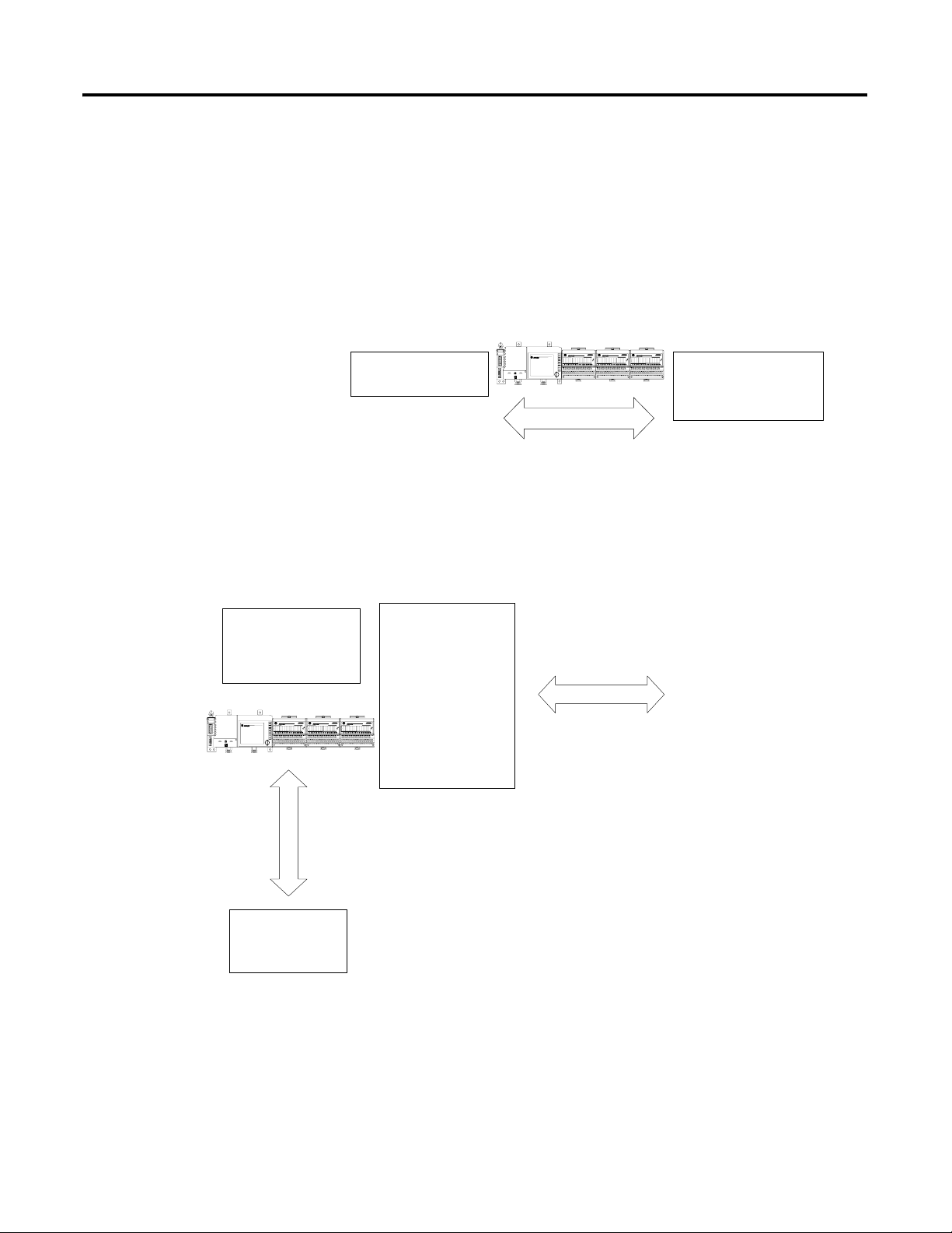
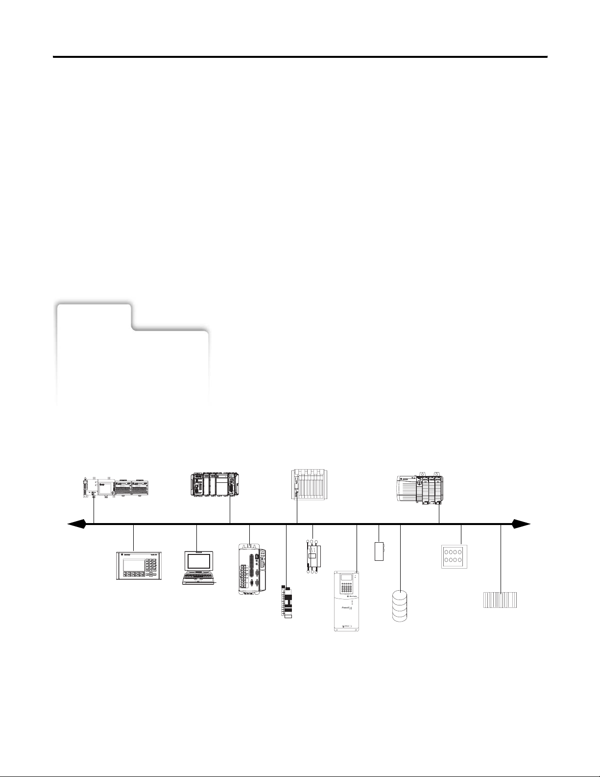
The FlexLogix controller offers state-of-art control, communications,
and I/O elements in a distributed control package..
FlexLogix controller
For a more flexible system, use:
• multiple controllers joined across networks
• I/O from multiple platforms that is distributed in many locations
and connected over multiple I/O links
network communication
cards installed in
the controller
EtherNet/IP link
1794 I/O modules
connected to the
FlexLogix controller
remote I/O modules
drives
}
ControlNet link
EtherNet/IP link
ControlNet link
DeviceNet
computers
other controllers
11 Publication 1794-UM001G-EN-P - January 2007
Page 12

12 Where to Start
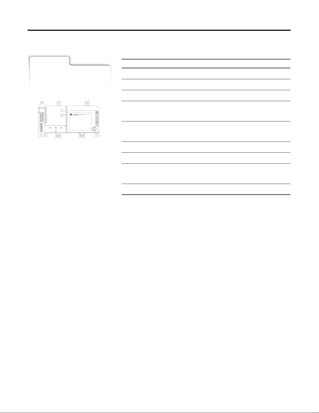
The FlexLogix controller, part of the Logix family of controllers,
provides a small, powerful, cost-effective system built on the
following components:
• 1794-L34 FlexLogix controller available in 512 Kbytes of
user memory.
• FlexLogix controller that supports the Logix instructions.
• RSLogix 5000 programming software that supports every
Logix controller.
• FLEX I/O modules that provide a compact, DIN-rail mounted
I/O system.
• 1788 communication daughtercard that provides communication
over standard-based ControlNet, DeviceNet or EtherNet/IP
networks. The controller allows the insertion of daughtercards
for up to 2 networks (e.g., one for DeviceNet and one for
EtherNet/IP).
Design
See:
• FlexLogix Selection Guide,
1794-SG001
• Logix5000 Controller Design
Considerations Reference Manual,
1756-RM094
When designing a FlexLogix system, determine the network
configuration and the placement of components in each location.
Make these decisions as you design your system:
Design Step
o 1.
o 2.
o 3.
o 4.
o 5.
Select I/O devices
Select communication cards
Select controllers
Select power supplies
Select software
Publication 1794-UM001G-EN-P - January 2007
Page 13
Where to Start 13
Install Hardware
See:
• FlexLogix Controller Installation
To install a FlexLogix controller, follow these steps:
Installation Step
o 1.
o 2.
o 3.
o 4.
o 5.
o 6.
o 7.
o 8.
o 9.
Install a DIN rail
Use DIN rail locks that came with your controller
Mount an appropriate power supply on the DIN rail
Install the battery in the controller
See 8 “Maintain the Battery.“
Install the communication cards in the controller
See Chapter 3 “Communicate over Networks”
Install the controller on the DIN rail
Install the extended-local adapter (optional)
Make serial connections
See Chapter 2 “Directly Connect to the Controller via the Serial Port “
Load controller firmware
Publication 1794-UM001G-EN-P - January 2007
Page 14

14 Where to Start
Notes:
Publication 1794-UM001G-EN-P - January 2007
Page 15
Chapter
2
Directly Connect to the Controller via the
Serial Port
Use This Chapter
See:
• EtherNet/IP Modules in Logix5000
Control Systems User Manual,
ENET-UM001
• ControlNet Modules in Logix5000
Control System User Manual,
CNET-UM001
• DeviceNet Modules in Logix5000
Control System User Manual,
DNET-UM004
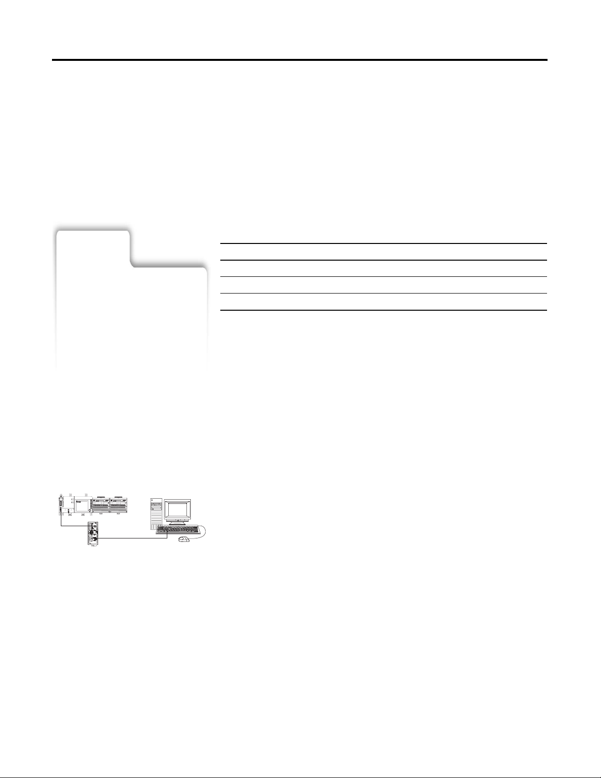
Connect the Controller via the Serial Port
This chapter describes how to connect to the controller via the serial
port so you can configure the controller and upload and/or download
a project to the controller.
For this information See
Connect the Controller via the Serial Port 15
Configure the Serial Driver 18
Select the Controller Path 20
For the FlexLogix controller to operate on a serial network, you need:
• a workstation with a serial port
• RSLinx software to configure the serial communication driver
• RSLogix5000 programming software to configure the serial port
of the controller
The RS-232 port is a non-isolated serial port built-in to the front of the
FlexLogix controller.
1. Determine whether you need an isolator.
If you connect the controller to a modem or an ASCII device,
consider installing an isolator between the controller and
modem or ASCII device. An isolator is also recommended when
connecting the controller directly to a programming workstation.
15 Publication 1794-UM001G-EN-P - January 2007
Page 16
16 Directly Connect to the Controller via the Serial Port
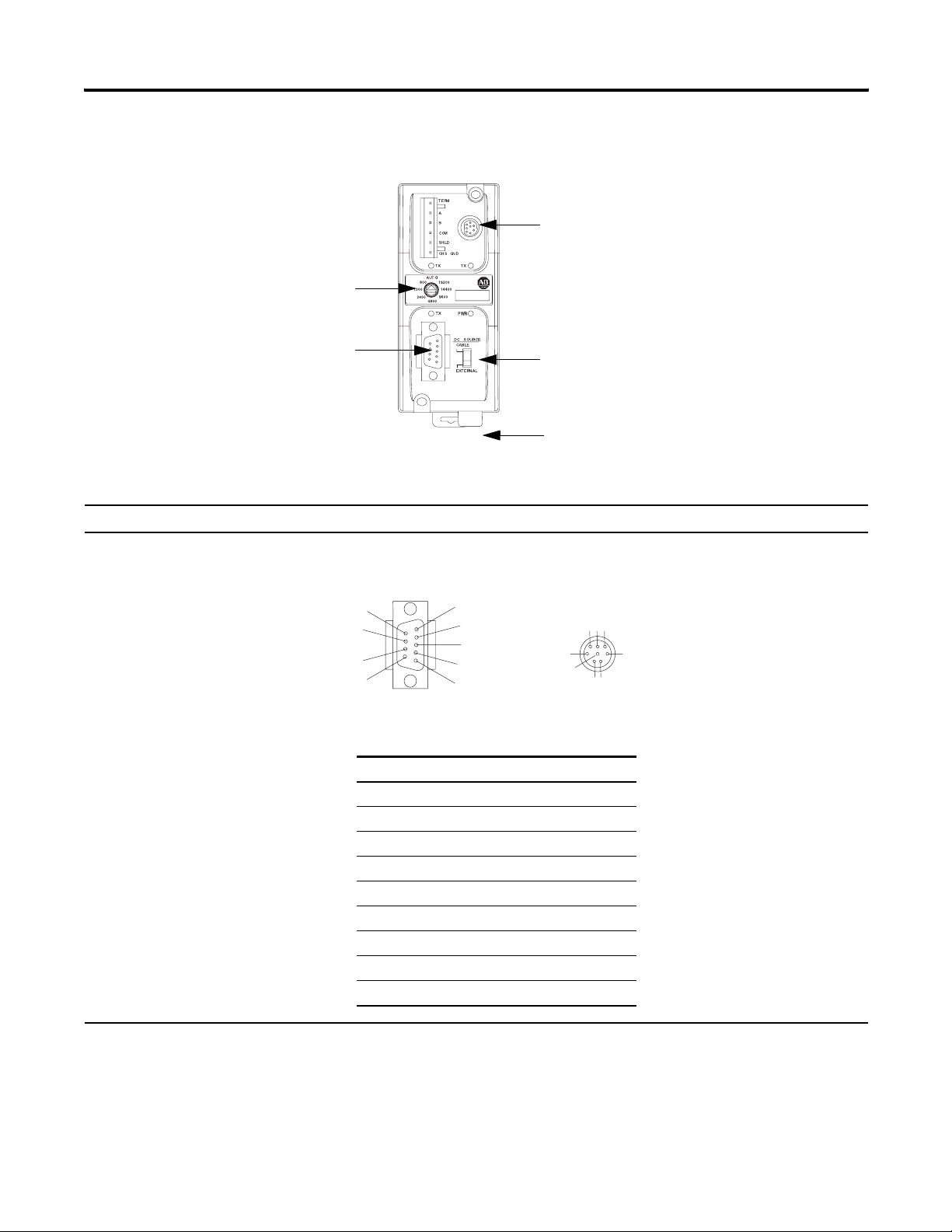
5
8
baud rate selector switch
One possible isolator is the 1761-NET-AIC interface converter.
port 2: mini-DIN 8 RS-232
port 1: DB-9 RS-232, DTE
dc power source selector switch
terminals for external 24V dc power supply
2. Select the appropriate cable.
If you are using an isolator: Use this cable:
yes The 1761-CBL-AP00 cable (right-angle bend connector to controller) or the 1761-CBL-PM02 cable
(straight connector to the controller) attaches the controller to port 2 on the 1761-NET-AIC isolator.
The 8-pin mini-DIN connector is not commercially available, so you cannot make this cable.
6
7
9
DB-9 right-angle or
straight cable end
Pin: DB-9 end: Mini-DIN end:
1DCD DCD
2 RxD RxD
3TxD TxD
4DTR DTR
5 ground ground
6DSR DSR
7 RTS RTS
8 CTS CTS
9na na
1
2
3
4
5
678
3
4
12
8-pin, mini-DIN
cable end
Publication 1794-UM001G-EN-P - January 2007
Page 17
Directly Connect to the Controller via the Serial Port 17
If you are using an isolator: Use this cable:
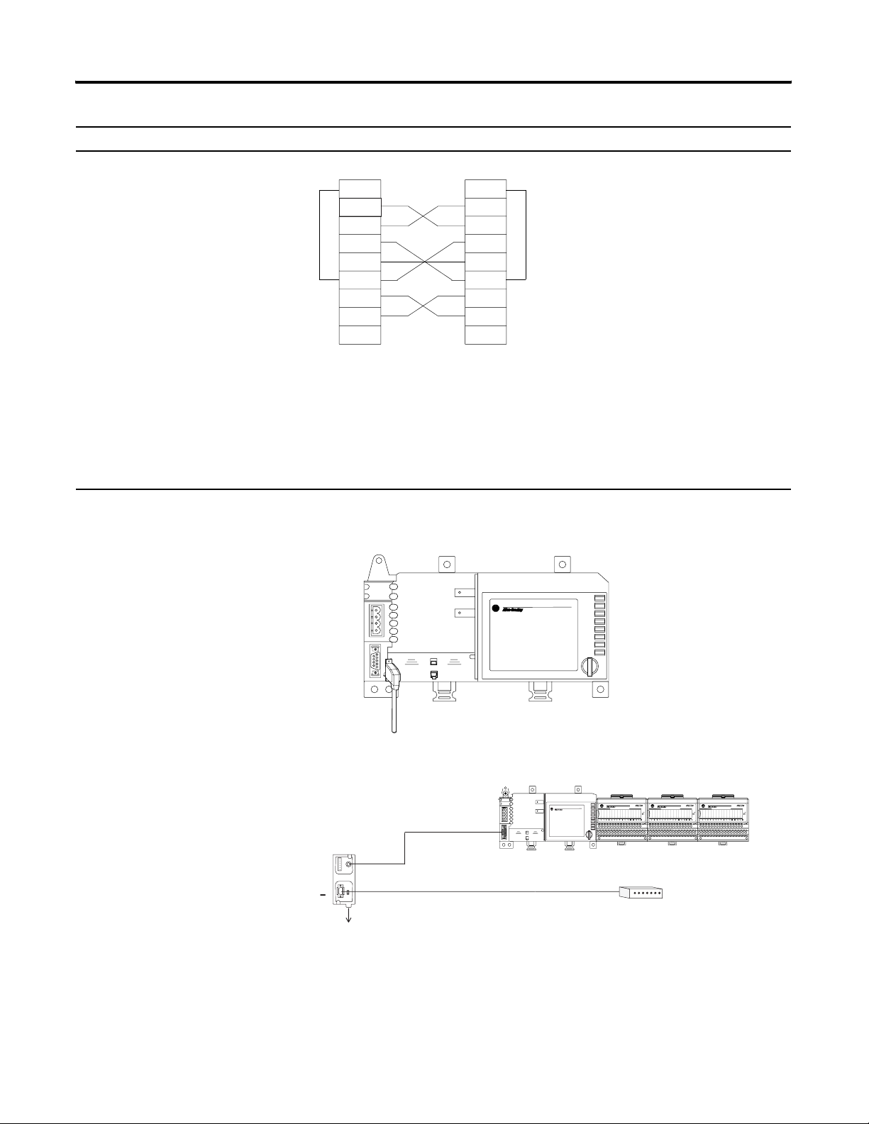
no The 1756-CP3 cable attaches the controller directly to the RS-232 device.
1 CD
2 RDX
3 TXD
4 DTR
COMMON
6 DSR
7 RTS
8 CTS
9
straight
cable end
1 CD
2 RDX
3 TXD
4 DTR
COMMON
6 DSR
7 RTS
8 CTS
9
right-angle
cable end
If you make your own cable, it must be shielded and the shields must be tied to the metal shell
(that surrounds the pins) on both ends of the cable.
You can also use a 1747-CP3 cable from the SLC product family. This cable has a larger right-angle
connector than the 1756-CP3 cable.
3. Connect the appropriate cable to the serial port on the
controller.
isolator
1761-NET-AIC
4. If necessary, attach the controller to the isolator.
1761 cable
user-supplied modem cable
modem
24 V dc
Publication 1794-UM001G-EN-P - January 2007
Page 18
18 Directly Connect to the Controller via the Serial Port
Configure the Serial Driver
ATTENTION
The FlexLogix controller is grounded through its DIN rail. It is
important that you understand the workstation’s grounding
system before connecting it to the controller. An isolator is
CH
recommended between the controller and the workstation.
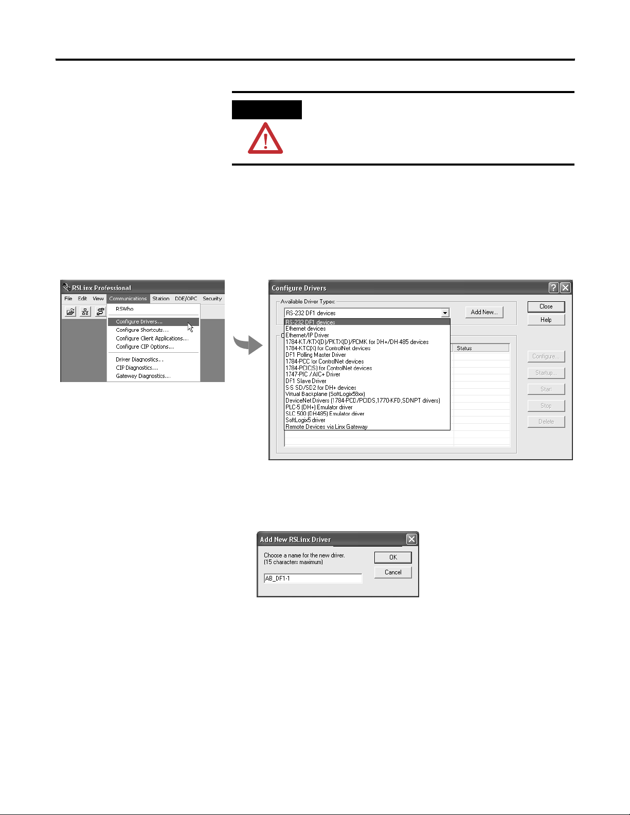
Use RSLinx software to configure the RS-232 DF1 Device driver for
serial communications. To configure the driver:
1. From the Communications menu in RSLinx software, select
Configure Drivers. Choose the RS-232 DF1 Device driver.
Publication 1794-UM001G-EN-P - January 2007
2. Click Add New to add the driver.
3. Specify the driver name and click OK.
Page 19
Directly Connect to the Controller via the Serial Port 19
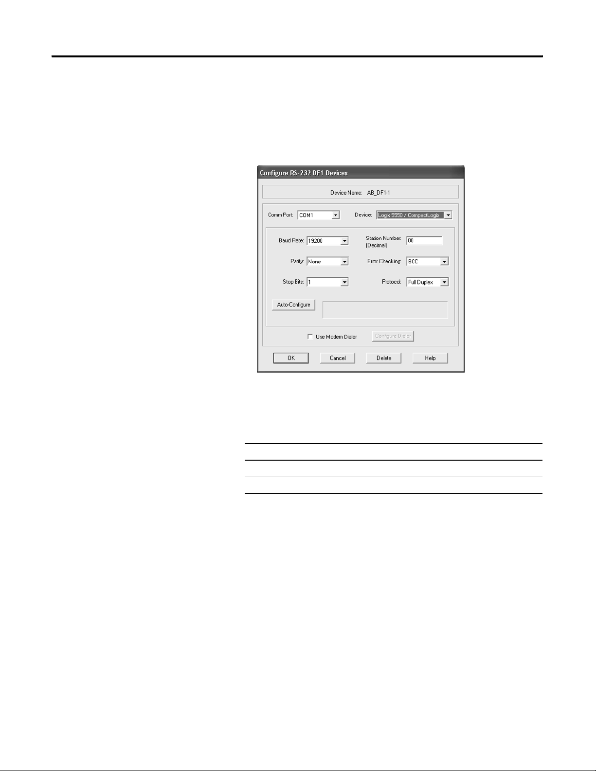
4. Specify the serial port settings:
a. From the Comm Port drop-down list, select the serial port (on
the workstation) that the cable is connected to.
b. From the Device drop-down list, select Logix 5550-Serial Port.
c. Click Auto-Configure.
5. Does the dialog box display the following message:
Auto Configuration Successful!
If: Then:
Yes Click OK.
No Go to step 4. and verify that you selected the correct Comm Port.
Then click Close.
Publication 1794-UM001G-EN-P - January 2007
Page 20
20 Directly Connect to the Controller via the Serial Port
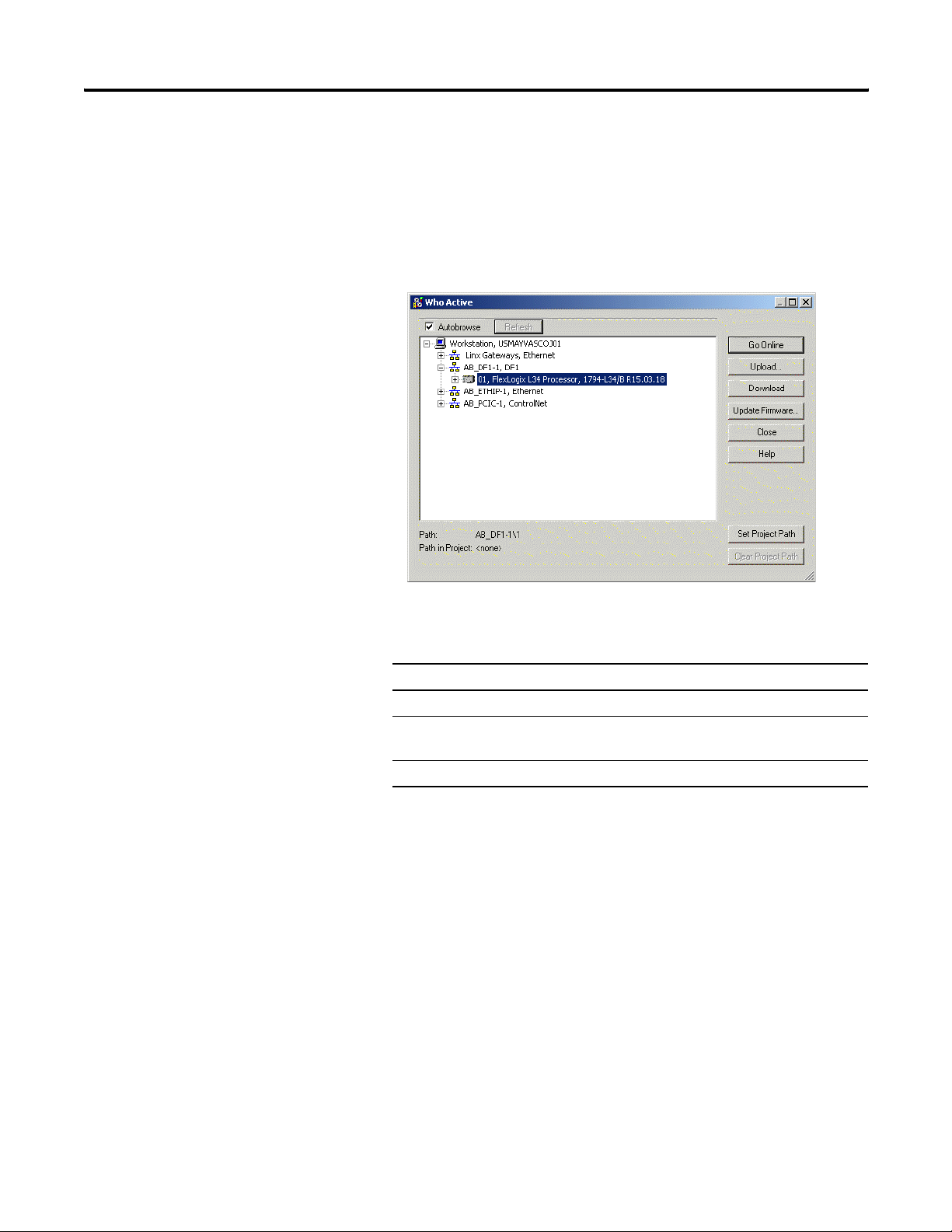
Select the Controller Path
In RSLogix 5000 software, select the controller path on the network.
1. Open an RSLogix 5000 project for the controller.
2. From the Communications menu, select Who Active.
3. Expand the communication driver to the level of the controller.
4. Select the controller.
To: Choose:
monitor the project in the controller Go Online
transfer a copy of the project from the controller to
RSLogix 5000 software
transfer the open project to the controller Download
You may have to confirm the action.
Upload
Publication 1794-UM001G-EN-P - January 2007
Page 21
Communicate over Networks
Chapter
3
Use This Chapter
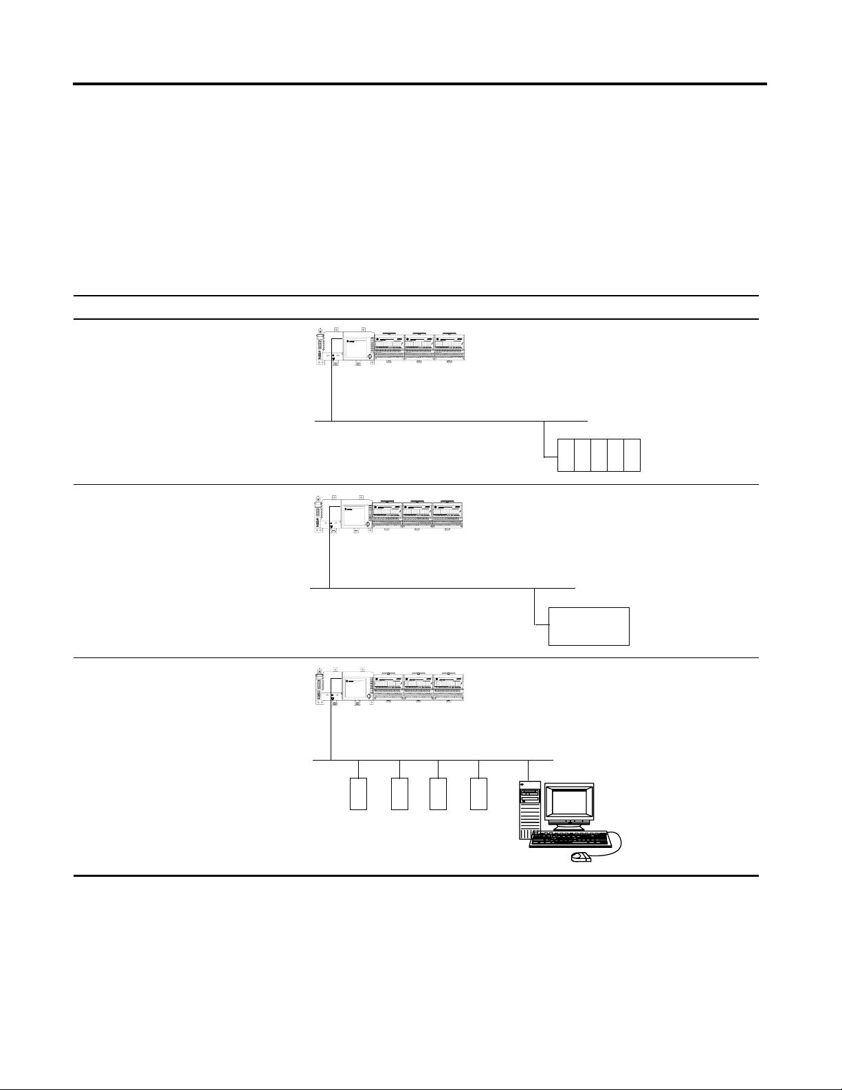
The FlexLogix controller supports additional networks so that the
controller can:
Supported networks for: Example:
Control distributed (remote) I/O
• EtherNet/IP
• ControlNet
• DeviceNet
Produce/consume (interlock) data between
controllers
• EtherNet/IP
• ControlNet
FlexLogix controller
control network
distributed (remote)
I/O platform
FlexLogix controller
control network
other Logix5000
controller
Send and receive messages to and from
other devices (this includes access to the
controller via RSLogix 5000 programming
software)
• EtherNet/IP
• ControlNet
• DeviceNet (to devices only)
• serial
• DH-485
21 Publication 1794-UM001G-EN-P - January 2007
control network
FlexLogix controller
other remote
devices
Page 22

22 Communicate over Networks
This chapter summarizes the FlexLogix controller’s
communications capabilities:
For this information: See:
EtherNet/IP 22
ControlNet 25
DeviceNet 28
Serial 31
DH-485 39
Third Party 42
EtherNet/IP
See:
• EtherNet/IP Modules in Logix5000
Control Systems User Manual,
ENET-UM001
• EtherNet/IP Web Server Module
User Manual, ENET-UM527
• EtherNet/IP Performance
Application Guide, ENET-AP001
• Logix5000 Controllers Design
Considerations Reference Manual,
1756-RM094
• EtherNet/IP Daughtercard
Installation Instructions,
1788-IN054
For EtherNet/IP communications, install a 1788-ENBT communication
card in your FlexLogix controller.
Use these software products when you use a FlexLogix controller on
EtherNet/IP:
Software Use Required/optional
RSLogix 5000 programming
software
Use this to configure the
FlexLogix project and define
EtherNet/IP
communications.
BOOTP/DHCP Utility
This utility comes with
RSLogix 5000 software. Use
this utility to assign IP
addresses to devices on an
EtherNet/IP network.
RSNetWorx for EtherNet/IP Use this software to
configure EtherNet/IP
devices by IP addresses
and/or host names.
Required
Optional
Optional
Publication 1794-UM001G-EN-P - January 2007
Page 23
Communicate over Networks 23
The EtherNet/IP communication modules:
• support messaging, produced/consumed tags, HMI, and
distributed I/O
• encapsulate messages within standard TCP/UDP/IP protocol
• share a common application layer with ControlNet and
DeviceNet
• interface via RJ45, category 5, unshielded, twisted-pair cable
• support half/full duplex 10 Mbps or 100 Mbps operation
• support standard switches
• require no network scheduling
• require no routing tables
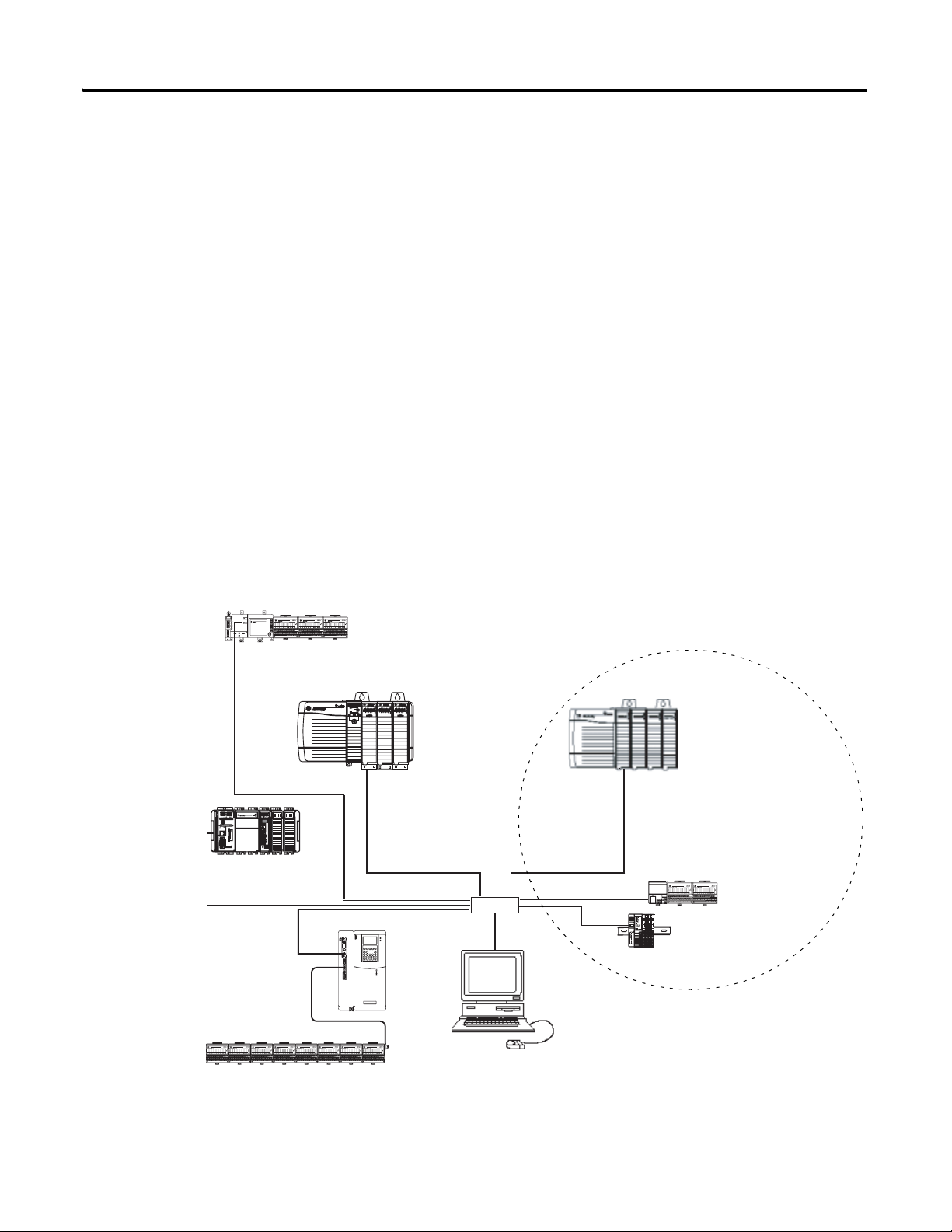
In this example:
• The controllers can produce and consume tags among each
other.
• The controllers can initiate MSG instructions that send/receive
data or configure devices.
• The personal computer can upload/download projects to
the controllers.
• The personal computer can configure devices on EtherNet/IP.
CompactLogix controller
with integrated
EtherNet/IP port
PowerFlex 700S AC
drive with DriveLogix
FlexLogix controller with
1788-ENBT card
ControlLogix
controller with
1756-ENBT
module
switch
workstation
Distributed I/O
1756-ENBT module
(as an adapter) with 1756
I/O modules
1794-AENT adapter with
1794 I/O modules
1734-AENT adapter
with 1734 I/O
modules
Publication 1794-UM001G-EN-P - January 2007
Page 24

24 Communicate over Networks
Connections over EtherNet/IP
You indirectly determine the number of connections the controller
uses by configuring the controller to communicate with other devices
in the system. Connections are allocations of resources that provide
more reliable communications between devices than unconnected
messages.
All EtherNet/IP connections are unscheduled. An unscheduled
connection is a message transfer between controllers that is triggered
by the requested packet interval (RPI) or the program (such as a MSG
instruction). Unscheduled messaging lets you send and receive data
when needed.
The 1788-ENBT card supports 32 CIP connections over an EtherNet/IP
network. With these controllers, the number of end-node connections
they effectively support is dependent on the RPI of the connection:
If the RPI is: The EtherNet/IP card effectively
supports a maximum of this many
communication connections:
2 ms 2
For more information...
4 ms 5
8 ms 10
16 ms 18
32 ms + 25
In the table above, with an RPI of 32 ms and greater, the EtherNet/IP
card effectively supports 25 communications connections. In this case,
the remaining 7 connections can be used for non-I/O purposes.
The EtherNet/IP Modules in Logix5000 Control Systems User Manual,
ENET-UM001 provides information on how to:
• configure an EtherNet/IP communication module
• control I/O over EtherNet/IP
• send a message over EtherNet/IP
• produce/consume a tag over EtherNet/IP
• monitor diagnostics
• calculate controller connections over EtherNet/IP
The Logix5000 Controllers Design Guidelines Reference Manual,
1756-RM094 provides guidelines on optimizing a control application
on an EtherNet/IP network.
Publication 1794-UM001G-EN-P - January 2007
Page 25

Communicate over Networks 25
ControlNet
See:
• ControlNet Modules in Logix5000
Control Systems User Manual,
CNET-UM001
• Logix5000 Controllers Design
Considerations Reference Manual,
1756-RM094
• ControlNet Daughtercard
Installation Instructions,
1788-IN002
• ControlNet Daughtercard
Installation Instructions,
For ControlNet communications, install a ControlNet communication
card in your FlexLogix controller:
If you are using Use this card
fiber media 1788-CNF, 1788-CNFR
coaxial media 1788-CNC, 1788-CNCR
Use these software products when you use a FlexLogix controller
on ControlNet:
Software Use Required/optional
RSLogix 5000 programming
software
RSLinx Use this software to
RSNetWorx for ControlNet Use this software to
Use this to configure the
FlexLogix project and define
ControlNet communications.
configure the ControlNet
communication driver.
configure the ControlNet
network, define the NUT
(Network update time), and
schedule the ControlNet
network.
Required
Required
Required
The ControlNet communications modules:
• support messaging, produced/consumed tags and distributed
I/O
• share a common application layer with DeviceNet and
EtherNet/IP
• require no routing tables
• support the use of coax and fiber repeaters for isolation and
increased distance
Publication 1794-UM001G-EN-P - January 2007
Page 26
26 Communicate over Networks
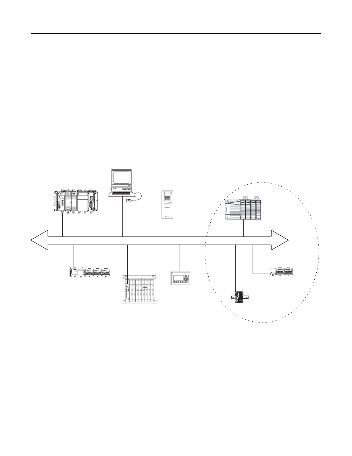
In this example:
• The controllers can produce and consume tags among
each other.
• The controllers can initiate MSG instructions that send/receive
data or configure devices.
• The personal computer can upload/download projects to the
controllers.
• The personal computer can configure devices on ControlNet,
and it can configure the network itself.
personal computer/workstation
CompactLogix controller
with built-in Control port
FlexLogix controller with
1788-CNC card
PowerFlex 700S drive
ControlNet
PLC-5/40C controller
PanelView terminal
Distributed I/O
1756-CNB module
(as an adapter) with
1756 I/O modules
1794-ACN15 adapter
with 1794 I/O modules
1734-ACNR adapter with
1734 I/O modules
Publication 1794-UM001G-EN-P - January 2007
Connections over ControlNet
You indirectly determine the number of connections the controller
uses by configuring the controller to communicate with other devices
in the system. Connections are allocations of resources that provide
Page 27

more reliable communications between devices compared to
unconnected messages.
ControlNet connections can be:
Connection method: Description:
Communicate over Networks 27
scheduled
(unique to ControlNet)
unscheduled An unscheduled connection is a message transfer between controllers that is triggered by
A scheduled connection is unique to ControlNet communications. A scheduled connection
lets you send and receive data repeatedly at a predetermined interval, which is the
requested packet interval (RPI). For example, a connection to an I/O module is a scheduled
connection because you repeatedly receive data from the module at a specified interval.
Other scheduled connections include connections to:
• communication devices
• produced/consumed tags
On a ControlNet network, you must use RSNetWorx for ControlNet to enable all scheduled
connections and establish a network update time (NUT). Scheduling a connection reserves
network bandwidth to specifically handle the connection.
ladder logic or the program (such as a MSG instruction). Unscheduled messaging lets you
send and receive data when needed. Unscheduled messages use the remainder of
network bandwidth after scheduled connections are allocated.
The FlexLogix controller supports 100 connections. However, the
controller is limited by the number of connections each ControlNet
communication card supports. The 1788-CNx cards support 32 total
ControlNet connections, 22 of which can be scheduled and used for
producing and consuming tags. With these controllers, the number of
end-node connections they effectively support is dependent on the
application’s NUT and RPI:
If the NUT and RPI are each: The controllers effectively support this
many communication connections
5 ms 3
10 ms 6
20 ms 13
40 ms + 22
In the table above, with a NUT and RPI of 40 ms and greater, the
ControlNet card supports 22 communications connections. In this
case, the remaining 10 connections can be used for unscheduled
connections.
Publication 1794-UM001G-EN-P - January 2007
Page 28
28 Communicate over Networks
For more information...
DeviceNet
See:
• DeviceNet Modules in Logix5000
Control Systems User Manual,
DNET-UM004
• Logix5000 Controllers Design
Considerations Reference Manual,
1756-RM094
• DeviceNet Daughtercard
The ControlNet Modules in Logix5000 Control Systems User Manual,
CNET-UM001 provides information on how to:
• configure a ControNet communication module
• control I/O over ControlNet
• send a message over ControlNet
• produce/consume a tag over ControlNet
• calculate controller connections over ControlNet
The Logix5000 Controllers Design Guidelines Reference Manual,
1756-RM094 provides guidelines on optimizing a control application
on a ControlNet network.
The DeviceNet network uses the Common Industrial Protocol (CIP) to
provide the control, configuration, and data collection capabilities for
industrial devices.
For DeviceNet communications, install a 1788-DNBO communication
card in your FlexLogix controller.
FlexLogix system with
1788-DNBO card
PanelView
terminal
CompactLogix controller
with 1769-SDN
laptop
Ultra 5000
servo drive
PLC-5 controller with
1771-SDN scanner module
DeviceNet network
motor
starter
input/output
devices
PowerFlex
ac drive
sensor
indicator
lights
ControlLogix controller
with 1756-DNB module
pushbutton
cluster
bar code
scanner
Publication 1794-UM001G-EN-P - January 2007
Page 29
Communicate over Networks 29
Use these software products when you use a FlexLogix controller
on DeviceNet:
Software Use Required/optional
RSLogix 5000 programming
software
Use this to configure the
FlexLogix project and define
Required
DeviceNet communications.
RSNetWorx for DeviceNet Use this software to
Required
configure DeviceNet devices
and define the scan list for
those devices.
The DeviceNet communications module:
• supports messaging to devices (not controller to controller)
• shares a common application layer with ControlNet and
EtherNet/IP
• offers diagnostics for improved data collection and fault
detection
• requires less wiring than traditional, hardwired systems
personal computer
FlexLogix system with
a 1788-DNBO card
You can use a linking device as a:
• gateway to connect information- or control-level networks to
device-level networks for programming, configuration, control
or data collection
• router/bridge to connect the EtherNet/IP or ControlNet network
to the DeviceNet network
ControlLogix controller
with 1756-ENBT module
EtherNet/IP network
FlexLogix controller
FLEX adapter and I/O
linking
devices
DeviceNet network
sensor
motor
starter
with a 1788-ENBT card
pushbutton
cluster
input/output
devices
PowerFlex
ac drive
bar code
indicator
lights
Publication 1794-UM001G-EN-P - January 2007
scanner
Page 30

30 Communicate over Networks
Define Data Blocks
How you configure the DeviceNet devices determines how many
words you use per device. The 1788-DNBO card supports a maximum
of:
• 124 32-bit words of input data
• 123 32-bit words of output data
• 32 32-bit words of status data
Most DeviceNet devices support 16-bit words. Take care how you
map these into the 32-bit words used in RSLogix 5000 programming
software. RSNetWorx for DeviceNet lets you DINT-align the device
data. While this might simplify the organization of the data, it might
also limit the data you have available.
For more information...
The DeviceNet Modules in Logix5000 Control Systems User Manual,
DNET-UM004 provides information on how to:
• configure DeviceNet communication module
• control devices on DeviceNet
The Logix5000 Controllers Design Guidelines Reference Manual,
1756-RM094 provides guidelines on optimizing a control application
on a DeviceNet network.
Publication 1794-UM001G-EN-P - January 2007
Page 31

Communicate over Networks 31
Serial
See:
• Logix5000 Controllers Common
Procedures Manual, 1756-PM001
The RS-232 port is a non-isolated serial port built-in to the front of the
FlexLogix controller. You can configure the serial port of the controller
for these modes:
Use this mode: For:
DF1
point-to-point
DF1 master mode control of polling and message transmission between the master and
communication between the controller and one other
DF1-protocol-compatible device.
This is the default system mode. Default parameters are:
• Baud Rate: 19200
• Data Bits: 8
• Parity: None
• Stop Bits: 1
• Control Line: No Handshake
• RTS send Delay: 0
• RTS Off Delay: 0
This mode is typically used to program the controller through its
serial port.
slave nodes.
DF1 radio modem
The master/slave network includes one controller configured as the
master node and as many as 254 slave nodes. Link slave nodes using
modems or line drivers.
A master/slave network can have node numbers from 0 to 254. Each
node must have a unique node address. Also, at least 2 nodes must
exist to define your link as a network (1 master and 1 slave station are
the two nodes).
• Compatible with SLC500 and MicroLogix1500 controllers
• This mode supports master and slave, and store and forward
modes
Publication 1794-UM001G-EN-P - January 2007
Page 32

32 Communicate over Networks
Use this mode: For:
DF1 slave mode using a controller as a slave station in a master/slave serial
communication network.
When there are multiple slave stations on the network, link slave
stations using modems or line drivers to the master. When you have a
single slave station on the network, you do not need a modem to
connect the slave station to the master. You can configure the control
parameters for no handshaking. You can connect 2 to 255 nodes to a
single link. In DF1 slave mode, a controller uses DF1 half-duplex
protocol.
One node is designated as the master and it controls who has access
to the link. All the other nodes are slave stations and must wait for
permission from the master before transmitting.
User mode
communicating with ASCII devices.
(channel 0 only)
This requires your program to use ASCII instructions to read and write
data from and to an ASCII device.
DH-485 communicating with other DH-485 devices multi-master, token
passing network allowing programming and peer-to-peer messaging.
Publication 1794-UM001G-EN-P - January 2007
Page 33

Communicate over Networks 33
1. Determine whether you need an isolator.
For more information on determining if you need an isolator,
see
page 15.
2. Select the appropriate cable.
3. Connect the appropriate cable to the serial port.
Communicate with DF1 devices
You can configure the controller as a master or slave on a serial
communication network. Use serial to get information to and from
remote controllers (stations) when:
• the system contains three or more stations
• communications occur on a regular basis and require
leased-line, radio, or power-line modems
EtherNet/IP
RS-232
RS-232
modem
modem
Isolator
RS-232
modem
Publication 1794-UM001G-EN-P - January 2007
Page 34

34 Communicate over Networks
On this tab Do this
To configure the controller for DF1 communications:
1. Select System Mode
2. Specify communication settings
1. Select DF1 protocol
For more information...
2. Specify DF1 settings
The Logix5000 Controllers General Instructions Reference Manual,
1756-RM003 defines the instructions you can use to manipulate ASCII
characters.
The SCADA System Application Guide, AG-UM008 provides
information on how to:
• select a polling mode
• configure controllers, modems, and software
• troubleshoot basic DF1 protocol issues
Publication 1794-UM001G-EN-P - January 2007
Page 35

Communicate over Networks 35
Communicate with ASCII devices
When configured for user mode, you can use the serial port to
interface with ASCII devices. For example, you can use the serial port
to:
• read ASCII characters from a weigh scale module or bar code
reader
• send and receive messages from an ASCII triggered device, such
as a MessageView terminal.
connection from the serial port of the controller to the ASCII device
Publication 1794-UM001G-EN-P - January 2007
Page 36

36 Communicate over Networks
On this tab Do this
To configure the controller for ASCII communications:
1. Select User Mode
2. Specify communication settings
1. Select ASCII protocol
2. Specify ASCII character settings
Publication 1794-UM001G-EN-P - January 2007
Page 37

Communicate over Networks 37
The controller supports several instructions to manipulate ASCII
characters. The instructions are available in ladder diagram (LD) and
structured text (ST).
Read and write ASCII characters
If you want to: Use this instruction:
determine when the buffer contains termination characters ABL
count the characters in the buffer ACB
clear the buffer ACL
clear out ASCII Serial Port instructions that are currently
executing or are in the queue
obtain the status of the serial port control lines AHL
turn on or off the DTR signal
turn on or off the RTS signal
read a fixed number of characters ARD
read a varying number of characters, up to and including the
first set of termination characters
send characters and automatically append one or two
additional characters to mark the end of the data
ARL
AWA
send characters AWT
Create and modify strings of ASCII characters
If you want to: Use this instruction:
add characters to the end of a string CONCAT
delete characters from a string DELETE
determine the starting character of a sub-string FIND
insert characters into a string INSERT
extract characters from a string MID
Publication 1794-UM001G-EN-P - January 2007
Page 38

38 Communicate over Networks
Convert data to or from ASCII characters
If you want to: Use this instruction:
convert the ASCII representation of an integer value to a SINT,
INT, DINT, or REAL value
STOD
For more information...
convert the ASCII representation of a floating-point value to a
REAL value
convert a SINT, INT, DINT, or REAL value to a string of ASCII
characters
convert a REAL value to a string of ASCII characters RTOS
convert the letters in a string of ASCII characters to upper case UPPER
convert the letters in a string of ASCII characters to lower case LOWER
STOR
DTOS
The Logix5000 Controllers General Instructions Reference Manual,
1756-RM003 defines the instructions you can use to manipulate ASCII
characters.
The Logix5000 Controllers Common Procedures Manual, 1756-PM001
provides information on how to:
• communicate with an ASCII device
• transmit/receive ASCII characters
Modbus support
See:
• Logix5000 Controllers as Masters
or Slaves on Modbus Application
Solution, CIG-AP129
Publication 1794-UM001G-EN-P - January 2007
To use Logix5000 controllers on Modbus, you connect through the
serial port and execute specific ladder logic routines. A sample
controller project is available with RSLogix 5000 Enterprise
programming software. From RSLogix 5000 software, select Help
→
Vendor Sample Projects to display a list of available, sample projects.
Page 39

Communicate over Networks 39
DH-485
For DH-485 communication, use the serial port of the controller.
However, when using a FlexLogix controller, it is recommended that
you use NetLinx networks (EtherNet/IP, ControlNet, or DeviceNet)
because excessive traffic on a DH-485 network may make it
impractical to connect to a controller with RSLogix 5000 programming
software.
If your application uses: Select:
• connections to existing DH-485 networks
built-in serial port
The DH-485 protocol uses RS-485 half-duplex as its physical interface.
(RS-485 is a definition of electrical characteristics; it is not a protocol.)
You can configure the RS-232 port of the FlexLogix controller to act as
a DH-485 interface. By using a 1761-NET-AIC and the appropriate
RS-232 cable (1756-CP3 or 1747-CP3), a FlexLogix controller can send
and receive data on a DH-485 network.
FlexLogix controller
1747-CP3
or
1761-NET-AIC+
1761-CBL-AP00
or
connection from FlexLogix
controller to port 1 or port 2
DH-485 network
1747-CP3
or
1747-AIC
SLC 5/03 controller
Publication 1794-UM001G-EN-P - January 2007
Page 40

40 Communicate over Networks
On the DH-485 network, the FlexLogix controller can send and
receive messages to and from other controllers on the network.
IMPORTANT
A DH-485 network consists of multiple cable segments. Limit
the total length of all the segments to 1219m (4000 ft.).
For the controller to operate on a DH-485 network, you need:
• a 1761-NET-AIC interface converter for each controller you want
to put on the DH-485 network.
You can have two controllers for each 1761-NET-AIC converter,
but you need a different cable for each controller.
a. Connect the serial port of the controller to either port 1 or
port 2 of the 1761-NET-AIC converter.
b. Use the RS-485 port to connect the converter to the DH-485
network.
The cable you use to connect the controller depends on the port
you use on the 1761-NET-AIC converter.
If you connect to this port: Use this cable:
port 1
1747-CP3
DB-9 RS-232, DTE connection
port 2
mini-DIN 8 RS-232 connection
or
1761-CBL-AC00
1761-CBL-AP00
or
1761-CBL-PM02
Publication 1794-UM001G-EN-P - January 2007
Page 41

Communicate over Networks 41
• RSLogix 5000 programming software to configure the serial port
of the controller for DH-485 communications.
Specify these characteristics on the Serial Port tab (default values
are shown in bold):
Characteristic: Description:
Baud Rate Specifies the communication rate for the DH-485 port. All devices
Node Address Specifies the node address of the controller on the DH-485
Token Hold Factor Number of transmissions (plus retries) that a node holding a
Maximum Node
Address
on the same DH-485 network must be configured for the same
baud rate. Select 9600 or 19200 Kbps.
network. Select a number 1-31 decimal, inclusive.
To optimize network performance, assign node addresses in
sequential order. Initiators, such as personal computers, should
be assigned the lowest address numbers to minimize the time
required to initialize the network.
token can send onto the data link each time that it receives the
token. Enter a value between 1-4. The default is 1.
Specifies the maximum node address of all the devices on the
DH-485 network. Select a number 1-31 decimal, inclusive.
For more information...
To optimize network performance, make sure:
• the maximum node address is the highest node number being
used on the network
• that all the devices on the same DH-485 network have the
same selection for the maximum node address.
The Data Highway/Data Highway Plus/Data Highway II/Data
Highway-485 Cable Installation Manual, 1770-6.2.2 describes how to
plan and install a DH-485 network.
Publication 1794-UM001G-EN-P - January 2007
Page 42

42 Communicate over Networks
Third Party
The FlexLogix controller can operate on third-party networks. To
operate on a third-party network, install the 1788-MODULE generic
module communication card in the controller.
Use these software products when you use a FlexLogix controller on
third-party network:
Software Use Required/optional
RSLogix 5000 programming
software, Version 12 or later
Third-party software Software that configures
Use this to configure the
1788-MODULE card as part
of the FlexLogix system
the 1788-MODULE card on
the third-party network
Required
Required
Use RSLogix 5000 programming software to map the 1788-MODULE
card as part of the FlexLogix system. In the Controller Organizer, add
the card to the I/O Configuration folder.
Communication Format
The Communication Format field chooses a data type for information
transmitted between the controller and a remote device connected to
the 1788-MODULE communication card. This format creates an array
in the controller of whatever data type you choose for the input and
output data.
Connection Parameters
You must set connection parameters to define data identification and
connection size. An Assembly Instance and Data Size must be
assigned for input, output and configuration data.
Assembly Instance
The Assembly Instance is a number that identifies what data
transferred between the owner-controller and I/O module looks like.
You must create a map that defines your assembly instance entries.
Publication 1794-UM001G-EN-P - January 2007
Page 43

Communicate over Networks 43
Size
The size field determines how large the connections are between the
owner-controller and the I/O module. Connections are sent in sizes
matching the communications format data type selected. The default,
DINT, results in 32-bit quantities.
Complete your system configuration and develop your program logic.
Then download the project to the controller.
Publication 1794-UM001G-EN-P - January 2007
Page 44

44 Communicate over Networks
Notes:
Publication 1794-UM001G-EN-P - January 2007
Page 45

Use This Chapter
Chapter
Manage Controller Communications
For this information See
Produce and Consume (Interlock) Data 45
Send and Receive Messages 47
Connection Overview 49
Calculate Connection Use 50
Connections Example 52
4
Produce and Consume (Interlock) Data
See:
• Logix5000 Controllers Common
Procedures Manual, 1756-PM001
• Logix5000 Controllers Design
Considerations Reference Manual,
The controller supports the ability to produce (broadcast) and
consume (receive) system-shared tags over ControlNet or EtherNet/IP
networks. Produced and consumed tags each require connections.
Over ControlNet, produced and consumed tags are scheduled
connections.
controller_1
produced tag
controller_2
consumed tag
controller_3
consumed tag
controller_4
consumed tag
45 Publication 1794-UM001G-EN-P - January 2007
Page 46

46 Manage Controller Communications
This type of tag Description
produced
consumed Each consumed tag requires one connection for the controller that is consuming the tag.
A produced tag allows other controllers to consume the tag, which means that a controller
can receive the tag data from another controller. The producing controller uses one
connection for the produced tag and one connection for each consumer. The controller’s
communication device uses one connection for each consumer.
As you increase the number of controllers that can consume a produced tag, you also
reduce the number of connections the controller and communication device have available
for other operations, like communications and I/O.
The controller’s communication device uses one connection for each consumer.
For two controllers to share produced or consumed tags, both
controllers must be attached to the same control network (such as a
ControlNet or Ethernet/IP network). You cannot bridge produced and
consumed tags over two networks.
The total number of tags that can be produced or consumed is limited
by the number of available connections. If the controller uses all of its
connections for I/O and communication devices, no connections are
left for produced and consumed tags.
For more information...
The Logix5000 Controllers Common Procedures Manual, 1756-PM001
provides information on how to:
• produce a tag
• consume a tag
• produce a large array
The Logix5000 Controllers Design Considerations Reference Manual,
1756-RM094 provides guidelines on how to:
• create produced and consumed tags
• specify an RPI
• manage connections
Publication 1794-UM001G-EN-P - January 2007
Page 47

Manage Controller Communications 47
Send and Receive Messages
See:
• Logix5000 Controllers Common
Procedures Manual, 1756-PM001
• Logix5000 Controllers Design
Considerations Reference Manual,
Messages transfer data to other devices, such as other controllers or
operator interfaces. Messages use unscheduled connections to send or
receive data. Connected messages can leave the connection open
(cache) or close the connection when the message is done
transmitting.
This message type: With this
communication
method:
CIP data table read or write 33
PLC2, PLC3, PLC5, or SLC
(all types)
CIP generic
block-transfer read or write 33
(1)
You can connect CIP generic messages. But for most applications we recommend you
leave CIP generic messages unconnected.
(2)
Consider caching only if the target module requires a connection.
CIP
CIP with Source ID
DH+ 33
Is a connected
message:
your option
(1)
The message
can be cached:
(2)
3
Connected messages are unscheduled connections on both
ControlNet and EtherNet/IP networks.
Each message uses one connection, regardless of how many devices
are in the message path. You can programmatically change the target
of a MSG instruction to optimize message transfer time.
Determine whether to cache message connections
When you configure a MSG instruction, you have the option of
whether or not to cache the connection.
If the message executes Then
repeatedly Cache the connection.
This keeps the connection open and optimizes execution time. Opening a connection each
time the message executes increases execution time.
infrequently Do not cache the connection.
This closes the connection upon completion of the message, which frees up that
connection for other uses.
Publication 1794-UM001G-EN-P - January 2007
Page 48

48 Manage Controller Communications
The controller has the following limits on the number of connections
that you can cache:
For more information...
If you have this software
and firmware revision:
11.x or earlier • block transfer messages for up to 16 connections
12.x or later up to 32 total connections
Then you can cache:
• other types of messages up to 16 connections
The Logix5000 Controllers General Instructions Reference Manual,
1756-RM003 describes how to use the MSG instruction.
The Logix5000 Controllers Common Procedures Manual, 1756-PM001
provides information on how to:
• execute a MSG instruction
• get and set the number of unconnected buffers
• convert INT data to DINT data
• manage multiple MSG instructions
• send one MSG to multiple devices
Publication 1794-UM001G-EN-P - January 2007
Page 49

Manage Controller Communications 49
Connection Overview
See:
• Logix5000 Controllers Design
Considerations Reference Manual,
1756-RM094
A Logix5000 system uses a connection to establish a communication
link between two devices. Connections can be:
• controller to local I/O modules or local communication modules
• controller to remote I/O or remote communication modules
• controller to remote I/O (rack-optimized) modules
• produced and consumed tags
• messages
• controller access by RSLogix 5000 programming software
• controller access by RSLinx software for HMI or other
applications
The limit of connections may ultimately reside in the communication
module you use for the connection. If a message path routes through
a communication module, the connection related to the message also
counts towards the connection limit of that communication module.
This device Supports this many connections
FlexLogix controller 100
1788-CNx communication card 32
1788-DNBO communication card 2
For more information...
1788-ENBT communication card 32
Other controllers and communication modules support different
maximum numbers of connections.
The Logix5000 Controllers Design Considerations Reference Manual,
1756-RM094 describes how to optimize connection use.
Publication 1794-UM001G-EN-P - January 2007
Page 50

50 Manage Controller Communications
Calculate Connection Use
Connection Type: Device
rack-optimized connection for the local DIN rail and the extended-local DIN
rail
I/O module (rack-optimized connection) on local rail 0
I/O module (direct connection) on local rail 1
I/O module (rack-optimized connection) on extended-local rail 0
I/O module (direct connection) on extended-local rail 1
1788-CNx ControlNet communication card 0 0
1788-DNBO DeviceNet communication card (direct connection)
1788-ENBT Ethernet/IP communication card 0 0
(1)
FlexLogix controller connection to remote DeviceNet devices are accounted for in the 2 connections to the 1788-DNBO card.
To calculate the total number of local connections the controller uses:
Connections
Quantity:
212
(1)
per Device:
2
total
Remote connections depend on the communication module. The
number of connections the module itself supports determines how
many connections the controller can access through that module. To
calculate the total number of remote connections the controller uses:
Tota l
Connections:
Remote Connection Type Device
Quantity
remote ControlNet communication module
I/O configured as direct connection (none)
I/O configured as rack-optimized connection
remote I/O module over ControlNet (direct connection) 1
remote EtherNet/IP communication module
I/O configured as direct connection (none)
I/O configured as rack-optimized connection
remote I/O module over EtherNet/IP (direct connection) 1
remote device over DeviceNet
(accounted for in rack-optimized connection for optional 1788-DNBO card) 0
other remote communication adapter 1
produced tag
each consumer
consumed tag 1
Connections
per Device
0 or
1
0 or
1
1
1
Tota l
Connections
Publication 1794-UM001G-EN-P - January 2007
Page 51

Manage Controller Communications 51
Remote Connection Type Device
Quantity
message (depending on type) 1
block-transfer message 1
Connections
per Device
Tota l
Connections
total
Publication 1794-UM001G-EN-P - January 2007
Page 52

52 Manage Controller Communications
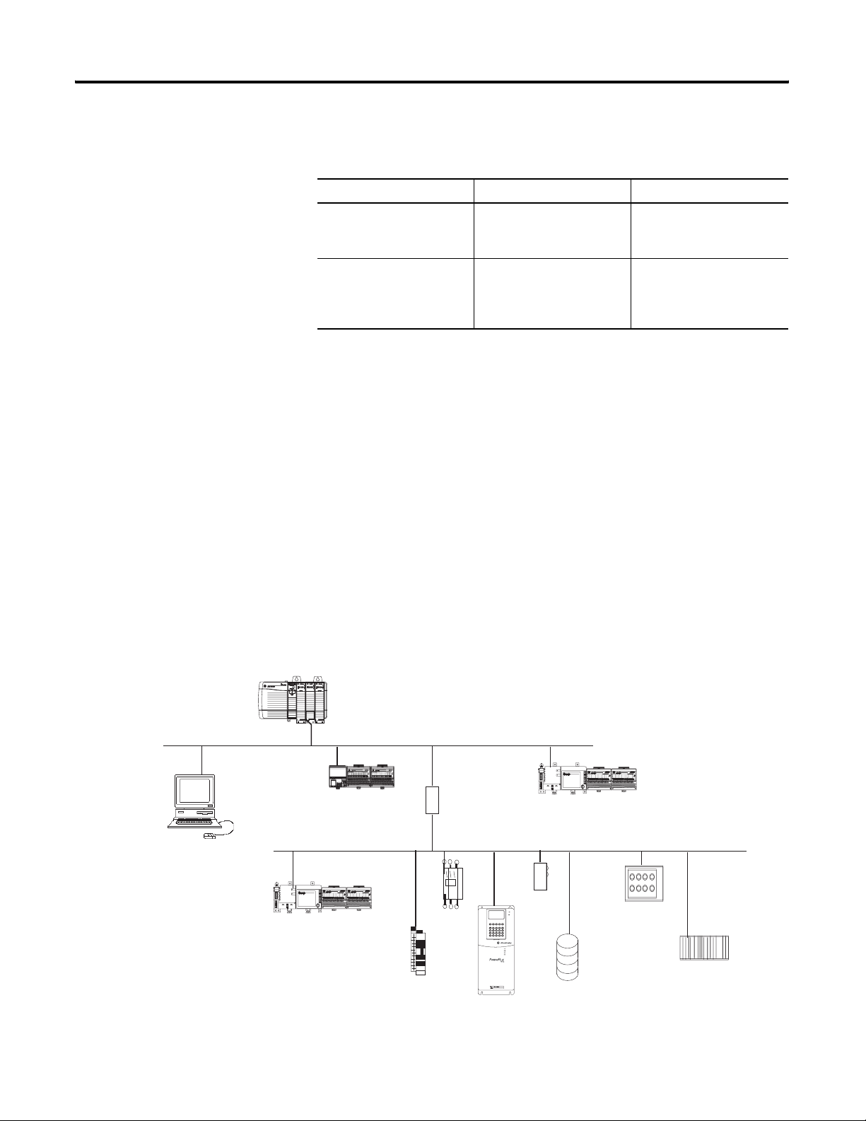
Connections Example
FlexLogix with 1788-DNBO and
1788-ENBT cards installed
In this example system the FlexLogix controller:
• controls local (in the same chassis) digital I/O modules
• controls remote I/O devices on DeviceNet
• sends and receives messages to/from a ControlLogix controller
on EtherNet/IP
• produces one tag that the the CompactLogix controller
consumes
• is programmed via RSLogix 5000 programming software
1769-ADN adapter with
Compact I/O modules
Redistation
Series 9000
photoeye
DeviceNet network
ControlLogix controller
with 1756-ENBT
module
EtherNet/IP network
1769-L35E CompactLogix
controller
personal computer
The FlexLogix controller in this example uses these connections:
Connection Type: Device
Quantity:
controller to local I/O modules (rack-optimized) 2 1 2
controller to installed DeviceNet communication card 1 2 2
controller to installed EtherNet/IP communication card 1 0 0
controller to RSLogix 5000 programming software 1 1 1
message to ControlLogix controller 2 1 2
produced tag consumed by CompactLogix controller 2 1 2
Connections
per Device:
Tota l
Connections:
Publication 1794-UM001G-EN-P - January 2007
total 9
Page 53

Use This Chapter
Chapter
Place, Configure, and Monitor I/O
For this information: See:
Select I/O Modules 53
Place Local I/O Modules 54
Configure I/O 55
Configure Distributed I/O on EtherNet/IP 59
Configure Distributed I/O on ControlNet 60
Configure Distributed I/O on DeviceNet 61
Address I/O Data 62
5
Select I/O Modules
See:
• FLEX I/O and FLEX EX Selection
Guide, 1794-SG002
Determine When Data Is Updated 63
Reconfigure an I/O Module 66
When selecting 1794 FLEX I/O modules, select:
• Select a communication adapter - Choose the network for your
operating system
• Select I/O modules based on field devices
• Select a terminal base - Choose an appropriate terminal base for
your modules
• Select power supplies and make sure there is sufficient power
for the communication adapter and modules
53 Publication 1794-UM001G-EN-P - January 2007
Page 54

54 Place, Configure, and Monitor I/O
Place Local I/O Modules
See:
• FLEX I/O Analog Modules User
Manual, 1794-6.5.2
• FLEX I/O Digital Modules User
The FlexLogix controller supports a local DIN rail of as many as 8 I/O
modules and an extended-local DIN rail of as many as 8 I/O modules.
The second DIN rail is optional.
local DIN rail
extended-local DIN rail
Selecting a Power Supply
In a FlexLogix system, select an Allen-Bradley power supply. In
applications that must be compliant with CSA requirements, use a
Separated Extra-Low Voltage (SELV) power supply that is compliant
with IEC 61010.1, Annex H.
When selecting power supplies:
• Provide power for the controller separately from the power for
the FLEX I/O modules. To provide power for FLEX I/O modules,
follow the guidelines in the documentation for those modules.
• When providing power for the 1794-FLA extended-local I/O
adapter, treat the adapter as a communication adapter, not as an
I/O module.
1794 FLEX power supplies
The following power supplies available for use with the FlexLogix
system.
Catalog number Nominal
input
voltage
1794-PS3 120/230V ac 85-265V ac 86W 205VA 250VA 3.0A @ 24V dc (horizontal
1794-PS13 36W 53VA 90VA 1.3A @ 24V dc
Input
voltage
range
Maximum
real input
power
Maximum
apparent input
power
Maximum
transformer
load
Output current
mount)
2.8A @ 24Vdc (non-horizontal
mount)
Publication 1794-UM001G-EN-P - January 2007
Page 55

Place, Configure, and Monitor I/O 55
The FlexLogix controller also supports distributed (remote) I/O via
these networks:
• EtherNet/IP
• ControlNet
• DeviceNet
Configure I/O
See:
• Logix5000 Controllers Common
Procedures Manual, 1756-PM001
• Logix5000 Controllers Design
Considerations Reference Manual,
1756-RM094
To communicate with an I/O module in your system, you add the
module to the I/O Configuration folder of the controller.
Add I/O modules
to the FlexBus
Local or Local2
Publication 1794-UM001G-EN-P - January 2007
Page 56

56 Place, Configure, and Monitor I/O
Configuration Option: Description:
requested packet interval (RPI) The RPI specifies the period at which data updates over a connection. For example, an
change of state (COS)
When you add a module, you also define a specific configuration for
the module. While the configuration options vary from module to
module, there are some common options that you typically configure:
input module sends data to a controller at the RPI that you assign to the module.
• Typically, you configure an RPI in milliseconds (ms). The range is 0.2 ms
(200 microseconds) to 750 ms.
• If a ControlNet network connects the devices, the RPI reserves a slot in the stream of
data flowing across the ControlNet network. The timing of this slot may not coincide
with the exact value of the RPI, but the control system guarantees that the data
transfers at least as often as the RPI.
Digital I/O modules use change of state (COS) to determine when to send data to the
controller. If a COS does not occur within the RPI timeframe, the module multicasts data at
the rate specified by the RPI.
Because the RPI and COS functions are asynchronous to the logic scan, it is possible for an
input to change state during program scan execution. If this is a concern, buffer input data
so your logic has a stable copy of data during its scan. Use the Synchronous Copy (CPS)
instruction to copy the input data from your input tags to another structure and use the
data from that structure.
communication format Many I/O modules support different formats. The communication format that you choose
also determines:
• data structure of tags
• connections
• network usage
• ownership
• whether the module returns diagnostic information
electronic keying When you configure a module, you specify the slot number for the module. However, it is
possible to place a different module in that slot, either on purpose or accidently. Electronic
keying lets you protect your system against the accidental placement of the wrong module
in a slot. The keying option you choose determines how closely any module in a slot must
match the configuration for that slot before the controller opens a connection to the
module. There are different keying options depending on your application needs.
Publication 1794-UM001G-EN-P - January 2007
Page 57

Place, Configure, and Monitor I/O 57
I/O connections
A Logix5000 system uses connections to transmit I/O data. A
connection can be:
Connection: Description:
direct A direct connection is a real-time, data transfer link between the controller and an I/O
module. The controller maintains and monitors the connection between the controller and
the I/O module. Any break in the connection, such as a module fault or the removal of a
module while under power, causes the controller to set fault status bits in the data area
associated with the module.
Typically, analog I/O modules, diagnostic I/O modules, and specialty modules require
direct connections.
rack-optimized For digital I/O modules, you can select rack-optimized communication. A rack-optimized
connection consolidates connection usage between the controller and all the digital I/O
modules on a rack (or DIN rail). Rather than having individual, direct connections for each
I/O module, there is one connection for the entire rack (or DIN rail).
Connections for local and extended-local I/O modules
The FlexLogix controller automatically assigns one rack-optimized
connection for the local DIN rail and one rack-optimized connection
for the extended-local DIN rail. You then configure each I/O module
on a DIN rail to either use that rack-optimized connection or to use a
direct connection. The rack-optimized connection for each DIN rail
exists whether or not you configure the I/O modules to use that
rack-optimized connection.
The rack-optimized connection lets you organize all the digital I/O
modules on one DIN rail into one connection to the controller. Or you
can choose to configure each I/O module to have a direct connection
to the controller. Analog I/O modules must have a direct connection
to the controller.
It is not as critical to manage the number of connections for local and
extended-local I/O modules as it is for remote devices because the
controller supports a direct connection for each possible local and
extended-local I/O device.
Publication 1794-UM001G-EN-P - January 2007
Page 58

58 Place, Configure, and Monitor I/O
Connections for remote devices
To optimize the number of available connections, place remote,
digital I/O in the same location and use a rack-optimized connection
to the remote adapter that connects the remote I/O to the FlexLogix
system.
If you have remote analog I/O modules, or want a direct connection
to specific remote I/O modules, you do not have to create the
rack-optimized connection to the remote adapter. To use direct
connections to remote I/O, select “none” for the communication
format of the remote communication device.
For more information...
IMPORTANT
It is vital that you manage your connections to remote devices
because, while the FlexLogix controller allows up to 100 total
connections, the communications cards that connect to remote
devices are limited to far fewer connections (i.e., 32
connections for ControlNet or EtherNet/IP).
The Logix5000 Controllers Common Procedures Manual, 1756-PM001
provides information on how to:
• configure I/O
• address I/O data
• buffer I/O data
The Logix5000 Controllers Design Guidelines Reference Manual,
1756-RM094 provides guidelines on how to:
• buffer I/O
• specify an RPI rate
• select a communication format
• manage I/O connections
Publication 1794-UM001G-EN-P - January 2007
Page 59

Place, Configure, and Monitor I/O 59
Configure Distributed I/O on EtherNet/IP
For a typical distributed I/O network…
controller
…you build the I/O configuration in this order
EtherNet/IP card
To communicate with distributed I/O modules over EtherNet/IP, you:
• install a 1788-ENBT communication card in your FlexLogix
controller and add the card to the I/O configuration folder
• add an EtherNet/IP adapter, and I/O modules to the I/O
Configuration folder of the controller.
Within the I/O Configuration folder, you organize the modules
into a hierarchy (tree/branch, parent/child).
remote
adapter
I/O
module
device
1. Add the local communication card
2. Add the remote adapter for the distributed
I/O chassis or DIN rail.
For more information...
See EtherNet/IP Communication Modules in Logix5000 Control
Systems User Manual, ENET-UM001.
Publication 1794-UM001G-EN-P - January 2007
Page 60

60 Place, Configure, and Monitor I/O
Configure Distributed I/O on ControlNet
For a typical distributed I/O network…
controller
…you build the I/O configuration in this order
built-n
ControlNet port
To communicate with distributed I/O modules over ControlNet, you:
• install a 1788-CNx communication card in your FlexLogix
controller and add the card to the I/O configuration folder
• add a ControlNet adapter, and I/O modules to the I/O
Configuration folder of the controller.
Within the I/O Configuration folder, you organize the modules
into a hierarchy (tree/branch, parent/child).
remote
adapter
I/O
module
device
1. Add the local communication card
2. Add the remote adapter for the distributed
I/O chassis or DIN rail.
For more information...
Publication 1794-UM001G-EN-P - January 2007
See ControlNet Communication Modules in Logix5000 Control Systems
User Manual, CNET-UM001.
Page 61

Place, Configure, and Monitor I/O 61
Configure Distributed I/O on DeviceNet
For a typical distributed I/O network…
single network
cardcontroller
several smaller distributed networks (subnets)
cardcontroller
device
device device device device
linking
device
device device device
To communicate with the I/O modules over Device, you add the
DeviceNet bridge to the I/O Configuration folder of the controller.
You define a scanlist within the DeviceNet adapter to communicate
data between devices and the controller.
device
linking
device
device device
…you build the I/O configuration in this order
Add the local scanner module.
For more information...
See DeviceNet Communication Modules in Logix5000 Control Systems
User Manual, DNET-UM004.
Publication 1794-UM001G-EN-P - January 2007
Page 62

62 Place, Configure, and Monitor I/O
Address I/O Data
I/O information is presented as a set of tags.
• Each tag uses a structure of data. The structure depends on the
specific features of the I/O module.
• The name of the tags is based on the location of the I/O module
in the system.
An I/O address follows this format:
Location :Slot :Type .Member .SubMember .Bit
Where: Is:
Location Network location
LOCAL = same chassis or DIN rail as the controller
ADAPTER_NAME = identifies remote communication adapter or bridge module
Slot Slot number of I/O module in its chassis or DIN rail
Type Type of data
I = input
O = output
= Optional
C = configuration
S = status
Member Specific data from the I/O module; depends on what type of data the module can store.
• For a digital module, a Data member usually stores the input or output bit values.
• For an analog module, a Channel member (CH#) usually stores the data for a channel.
SubMember Specific data related to a Member.
Bit Specific point on a digital I/O module; depends on the size of the I/O module (0-31 for a 32-point module)
Publication 1794-UM001G-EN-P - January 2007
Page 63

Place, Configure, and Monitor I/O 63
Determine When Data Is Updated
input or output data?
input
analog or digital?
analog
RTS ≤ RPI?
Yes
Data is sent to the backplane
at the RTS.
No
FlexLogix controllers update date asynchronous with the execution of
logic. Use the following flowchart to determine when a producer
(controller, input module, or bridge module) will send data.
output
digital
COS for any point on the
module?
Data is sent to the backplane at
the RTS and RPI.
Yes
analog or digital?
No
analog
remote or local?
remote
digital
local
Data is sent to the backplane at the RPI
and at the change of a specified point.
• Over a ControlNet network, remote data is sent at the actual packet interval.
• Over an EtherNet/IP network, remote data is sent close to the RPI, on average.
TIP
If you need to ensure that the I/O values being used during logic
execution are from one moment in time (such as at the
beginning of a ladder program), use the Synchronous Copy
instruction (CPS) to buffer I/O data.
For more information...
See Logix5000 Controllers Common Procedures Programming
Manual, publication number 1756-PM001 for examples of I/O
buffering or to the Logix5000 Controllers General Instruction Set
Reference Manual, publication number 1756-RM003 for information
on the CPS instruction.
Data is sent to the backplane at the
RPI
Data is sent to the backplane at the RPI
and at the end of every task.
Publication 1794-UM001G-EN-P - January 2007
Page 64

64 Place, Configure, and Monitor I/O
Monitor I/O Modules
The FlexLogix controller offers different levels at which you can
monitor I/O modules. You can:
• configure an I/O module so that the controller faults if that I/O
module loses its connection with the controller
• use the programming software to display fault data (Refer
to Displaying fault data on page 5-64)
• program logic to monitor fault data so you can take appropriate
action (Refer to Logix5000 Controllers Common Procedures
Programming Manual, publication number 1756-PM001, for
examples.)
Displaying fault data
Fault data for certain types of module faults can be viewed through
the programming software.
To view this data, select Controller Tags in the Controller Organizer.
Right-click to select Monitor Tags.
Publication 1794-UM001G-EN-P - January 2007
The display for the fault data defaults to decimal. Change it to Hex to
read the fault code.
Page 65

Place, Configure, and Monitor I/O 65
Monitor a rack-optimized connection
The controller views the DIN rail as another module in the system.
Each DIN rail has its own data. To view this data through the
programming software:
1. In the Controller Organizer, select Controller Tags. Right-click to
display the Data Monitor.
2. Expand the data display as necessary.
ATTENTION
If you have an extended-local DIN rail (LOCAL2) or a split rail,
the modules after the 1794-CE1, -CE3 cable will fault if the
cable is disconnected. In this case, all outputs are reset,
regardless of the module configurations.
You can write logic to monitor the rack bits and take appropriate
action if a fault occurs. For example, the following logic determines
whether an error occurs on the Local rail. Then, the logic determines
whether the error occurred at the module in slot 0. You can continue
this logic to check each module on the rail.
Publication 1794-UM001G-EN-P - January 2007
Page 66

66 Place, Configure, and Monitor I/O
Reconfigure an I/O Module
If an I/O module support reconfiguration, you can reconfigure the
module via:
• Module Properties dialog in RSLogix 5000 software
• MSG instruction in program logic
WARNING
Use care when changing the configuration of an I/O module.
You could inadvertently cause the I/O module to operate
incorrectly.
Reconfigure a module via RSLogix 5000 software
To change the configuration of an I/O module via RSLogix 5000
software, highlight the module in the I/O Configuration tree.
Right-click and select Properties.
Publication 1794-UM001G-EN-P - January 2007
Page 67

Place, Configure, and Monitor I/O 67
Reconfigure a module via a MSG instruction
To change the configuration of an I/O module programmatically, use
a MSG instruction of type Module Reconfigure to send new
configuration information to an I/O module. During the
reconfiguration:
• Input modules continue to send input data to the controller.
• Output modules continue to controller their output devices.
A Module Reconfigure message requires the following configuration
properties:
In this property: Select:
Message Type Module Reconfigure
To reconfigure an I/O module:
EXAMPLE
1. Set the required member of the configuration tag of the module
to the new value.
2. Send a Module Reconfigure message to the module.
Reconfigure an I/O module
When reconfigure[5] is on, the MOV instruction sets the high alarm to 60 for the local module in slot 4. The Module
Reconfigure message then sends the new alarm value to the module. The ONS instruction prevents the rung from
sending multiple messages to the module while the reconfigure[5] is on.
Publication 1794-UM001G-EN-P - January 2007
Page 68

68 Place, Configure, and Monitor I/O
Notes:
Publication 1794-UM001G-EN-P - January 2007
Page 69

Use This Chapter
Chapter
Develop Applications
For this information: See:
Manage Tasks 69
Develop Programs 70
Organize Tags 75
Select a Programming Language 76
Monitor Controller Status 79
Monitor Connections 80
Select a System Overhead Percentage 82
Use the Event Task 85
6
Manage Tasks
See:
• Logix5000 Controllers Common
Procedures Manual, 1756-PM001
• Logix5000 Controllers Design
Considerations Reference Manual,
A Logix5000 controller lets you use multiple tasks to schedule and
prioritize the execution of your programs based on specific criteria.
This balances the processing time of the controller among the
different operations in your application.
• The controller executes only one task at one time.
• A different task can interrupt a task that is executing and take
control.
• In any given task, only one program executes at one time.
69 Publication 1794-UM001G-EN-P - January 2007
Page 70

70 Develop Applications
Develop Programs
control application
task 1
The controller operating system is a preemptive multitasking system
that is IEC 1131-3 compliant. This environment provides:
• tasks to configure controller execution
• programs to group data and logic
• routines to encapsulate executable code written in a single
programming language
controller fault handler
task 8
configuration
status
program 32
watchdog
program 1
main routine
fault routine
controller (global) tags I/O data system-shared data
program (local)
tags
other routines
Publication 1794-UM001G-EN-P - January 2007
Page 71

Develop Applications 71
Defining tasks
A task provides scheduling and priority information for a set of one or
more programs. You can configure tasks as continuous, periodic, or
event. Only one task can be continuous.
A task can have as many as 100 separate programs, each with its own
executable routines and program-scoped tags. Once a task is triggered
(activated), all the programs assigned to the task execute in the order
in which they are grouped. Programs can only appear once in the
Controller Organizer and cannot be shared by multiple tasks.
Specifying task priorities
Each task in the controller has a priority level. The operating system
uses the priority level to determine which task to execute when
multiple tasks are triggered. You can configure periodic tasks to
execute from the lowest priority of 15 up to the highest priority of 1. A
higher priority task will interrupt any lower priority task. The
continuous task has the lowest priority and is always interrupted by a
periodic task.
The FlexLogix controller uses a dedicated periodic task at priority 6 to
process I/O data. This periodic task executes at the RPI you configure
for the FlexBus, which can be as fast as once every 2 ms. Its total
execution time is as long as it takes to scan the configured
I/O modules.
How you configure your tasks affects how the controller receives I/O
data. Tasks at priorities 1 to 5 take precedence over the dedicated I/O
task. Tasks in this priority range can impact I/O processing time.
For example, if you use the following configuration:
• I/O RPI = 2 ms
• a task of priority = 1 to 5 that requires 500 μs to execute and is
scheduled to run every millisecond
this configuration leaves the dedicated I/O task 500 μs to complete its
job of scanning the configured I/O.
Publication 1794-UM001G-EN-P - January 2007
Page 72

72 Develop Applications
0
5
However, if you schedule two high priority tasks (1 to 5) to run every
millisecond, and they both require 500 μs or more to execute, no CPU
time would be left for the dedicated I/O task. Furthermore, if you
have so much configured I/O that the execution time of the dedicated
I/O task approaches 2 ms (or the combination of the high priority
tasks and the dedicated I/O task approaches 2 ms) no CPU time is left
for low priority tasks (7 to 15).
TIP
For example, if your program needs to react to inputs and control outputs at a
deterministic rate, configure a periodic task with a priority higher than 5 (1 through
5). This keeps the dedicated I/O task from affecting the periodic rate of your
program. However, if your program contains a lot of math and data manipulation,
place this logic in a task with priority lower than 6 (7 through 15), such as the
continuous task, so that the dedicated I/O task is not adversely affected by your
program.
The following example shows the task execution order for an
application with periodic tasks and a continuous task.
Task: Priority Level: Task Type: Example Execution
Time:
1 5 20 ms periodic task 2 ms 2 ms
2 6 dedicated I/O task
5 ms selected RPI
3 10 10 ms periodic task 4 ms 8 ms
4 none (lowest) continuous task 25 ms 60 ms
1 ms 3 ms
Worst Case Completion
Time:
Tas k 1
Tas k 2
Tas k 3
Tas k 4
30252015105 454035 50 6
Time (ms)
Publication 1794-UM001G-EN-P - January 2007
6055
Page 73

Develop Applications 73
Notes:
A. The highest priority task interrupts all lower priority tasks.
B. The dedicated I/O task can be interrupted by tasks with priority
levels 1 to 7. The dedicated I/O task interrupts tasks with
priority levels 7 to 15. This task runs at the selected RPI rate
scheduled for the FlexLogix system (5 ms in this example).
C. The continuous task runs at the lowest priority and is
interrupted by all other tasks.
D. A lower priority task can be interrupted multiple times by a
higher priority task.
E. When the continuous task completes a full scan it restarts
immediately, unless a higher priority task is running.
Defining programs
Each program contains program tags, a main executable routine, other
routines, and an optional fault routine. Each task can schedule as
many as 100 programs.
The scheduled programs within a task execute to completion from
first to last. Programs that are not attached to any task show up as
unscheduled programs. You must specify (schedule) a program within
a task before the controller can scan the program.
Defining routines
A routine is a set of logic instructions in a single programming
language, such as ladder logic. Routines provide the executable code
for the project in a controller. A routine is similar to a program file or
subroutine in a PLC or SLC controller.
Each program has a main routine. This is the first routine to execute
when the controller triggers the associated task and calls the
associated program. Use logic, such as the Jump to Subroutine (JSR)
instruction, to call other routines.
You can also specify an optional program fault routine. The controller
executes this routine if it encounters an instruction-execution fault
within any of the routines in the associated program.
Publication 1794-UM001G-EN-P - January 2007
Page 74

74 Develop Applications
Sample controller projects
RSLogix 5000 Enterprise programming software includes sample
projects that you can copy and then modify to fit your application.
From RSlogix 5000 software, select Help
display a list of available, sample projects.
→ Vendor Sample Projects to
Scroll down to here and select the
appropriate set of sample projects
For more information...
The Logix5000 Controllers Common Procedures Manual, 1756-PM001
provides information on how to:
• select which task to use
• configure tasks
• prioritize tasks
• inhibit tasks
Publication 1794-UM001G-EN-P - January 2007
Page 75

Develop Applications 75
Organize Tags
See:
• Logix5000 Controllers Common
Procedures Manual, 1756-PM001
• Logix5000 Controllers Design
Considerations Reference Manual,
analog I/O device
integer value
storage bit
With a Logix5000 controller, you use a tag (alphanumeric name) to
address data (variables). In Logix5000 controllers, there is no fixed,
numeric format. The tag name itself identifies the data. This lets you:
• organize your data to mirror your machinery
• document (through tag names) your application as you
develop it
counter
timer
digital I/O device
For more information...
When you create a tag, you assign the following properties to the tag:
• tag type
• data type
• scope
The Logix5000 Controllers Common Procedures Manual, 1756-PM001
provides information on how to:
• define tags
• create tags, arrays, and user-defined structures
• address tags
• create aliases to tags
• assign indirect addresses
Publication 1794-UM001G-EN-P - January 2007
Page 76

76 Develop Applications
Select a Programming
The FlexLogix controller supports these programming languages, both
online and offline:
Language
If you are programming: Use this language:
continuous or parallel execution of multiple operations (not sequenced) ladder diagram (LD)
boolean or bit-based operations
complex logical operations
message and communication processing
machine interlocking
operations that service or maintenance personnel may have to interpret in order to
troubleshoot the machine or process
continuous process and drive control function block diagram (FBD)
loop control
calculations in circuit flow
high-level management of multiple operations sequential function chart (SFC)
repetitive sequence of operations
batch process
motion control using structured text
state machine operations
complex mathematical operations structured text (ST)
specialized array or table loop processing
ASCII string handling or protocol processing
Publication 1794-UM001G-EN-P - January 2007
Page 77

Develop Applications 77
Add-On Instructions
With version 16 of RSLogix 5000 programming software, you can
design and configure sets of commonly used instructions to increase
project consistency. Similar to the built-in instructions contained in
Logix5000 controllers, these instructions you create are called Add-On
Instructions. Add-On Instructions reuse common control algorithms.
With them, you can:
• ease maintenance by animating logic for a single instance.
• protect intellectual property with locking instructions.
• reduce documentation development time.
You can use Add-On Instructions across multiple projects. You can
define your instructions, obtain them from somebody else, or copy
them from another project.
Once defined in a project, Add-On Instructions behave similarly to the
built-in instructions in Logix5000 controllers. They appear on the
instruction tool bar for easy access, as do internal RSLogix 5000
software instructions.
Save Time
With Add-On Instructions, you can combine your most commonly
used logic into sets of reusable instructions. You save time when you
create instructions for your projects and then share them with others.
Add-On Instructions increase project consistency since commonly
used algorithms all work in the same manner, regardless of who
implements the project.
Use Standard Editors
You create Add-On Instructions by using one of three RSLogix 5000
software programming editors.
• Standard Ladder
• Function Block Diagram
• Structured Text
Once you have created instructions, you can use them in any RSLogix
5000 editor.
Export Add-On Instructions
You can export Add-On-Instructions to other projects as well as copy
and paste them from one project to another. Give each instruction a
Publication 1794-UM001G-EN-P - January 2007
Page 78

78 Develop Applications
unique name so that you don’t accidentally overwrite another
instruction of the same name.
Use Context Views
Context views let you visualize an instruction’s logic for a specific
instant, simplifying online troubleshooting of your Add-On
Instructions. Each instruction contains a revision, a change history,
and an auto-generated help page.
Create Custom Help
When you create an instruction, you enter information for the
description fields in software dialogs, information that becomes what
is known as Custom Help. Custom Help makes it easier for users to
get the help they need when implementing the instructions.
Apply Source Protection
For more information...
As the creator of Add-On Instructions, you can limit users of your
instruction(s) to read-only access, or you can bar access to the internal
logic or local parameters used by the instruction(s). This source
protection lets you prevent unwanted changes to your instruction(s)
and protects your intellectual property.
The Logix5000 Controllers Common Procedures Manual, 1756-PM001
provides information on how to:
• design and program sequential function chart (SFC) logic
• program structured text (ST) logic
• program ladder diagram (LD) logic
• program function block diagram (FBD) logic
• force logic
The Logix5000 Controllers Execution Time and Memory Use Reference
Manual, publication 1756-RM087 provides information on memory
use and execution times for instructions.
Publication 1794-UM001G-EN-P - January 2007
Page 79

Develop Applications 79
Monitor Controller Status
The FlexLogix controller uses Get System Value (GSV) and Set System
Value (SSV) instructions to get and set (change) controller data. The
controller stores system data in objects. There is no status file, as in
the PLC-5 processor.
The GSV instruction retrieves the specified information and places it
in the destination. The SSV instruction sets the specified attribute with
data from the source.
When you enter a GSV/SSV instruction, the programming software
displays the valid object classes, object names, and attribute names for
each instruction. For the GSV instruction, you can get values for all the
available attributes. For the SSV instruction, the software displays only
those attributes you are allowed to set.
In some cases, there will be more than one instance of the same type
of object, so you might also have to specify the object name. For
example, there can be several tasks in your application. Each task has
its own TASK object that you access by the task name.
You can access these object classes:
• AXIS
• CONTROLLER
• CONTROLLERDEVICE
• CST
• DF1
• FAULTLOG
• MESSAGE
• MODULE
• MOTIONGROUP
• PROGRAM
• ROUTINE
• SERIALPORT
• TASK
• WALLCLOCKTIME
For more information...
The Logix5000 Controllers General Instructions Reference Manual,
1756-RM003 describes how to use the GSV and SSV instructions.
These instructions support several different attributes of information.
The Logix5000 Controllers Common Procedures Manual, 1756-PM001
provides information on how to:
• handle major faults
• handle minor faults
• determine controller memory use
Publication 1794-UM001G-EN-P - January 2007
Page 80

80 Develop Applications
Monitor Connections
See:
• Logix5000 Controllers Common
Procedures Manual, 1756-PM001
• Logix5000 Controllers Design
Considerations Reference Manual,
If communication with a device in the I/O configuration of the
controller does not occur for 100 ms or 4 times the RPI (whichever is
less), the communication times out and the controller produces the
following warnings:
• The I/O LED on the front of the controller flashes green.
• A
shows over the I/O configuration folder and over the
!
device (s) that has timed out.
• A module fault code is produced, which you can access
through:
– Module Properties dialog box for the module
– GSV instruction
Determine if communication has timed out with any device
If communication times out with at least one device (module) in the
I/O configuration of the controller, the I/O LED on the front of the
controller flashes green.
• The GSV instruction gets the status of the I/O LED and stores it
in the I_O_LED tag.
• If I_O_LED equal 2, the controller has lost communication with
at least one device.
Get System Value
GSV
CIP Object Class MODULE
CIP Object Name
Attribute Name LedStatus
Dest I_O_LED
EQU
Equal
Source A I_O_LED
Source B 2
where:
I_O_LED is a DINT tag that stores the status of the I/O LED on
the front of the controller.
Determine if communication has timed out with a specific
I/O module
If communication times out with a device (module) in the I/O
configuration of the controller, the controller produces a fault code for
the module.
• The GSV instruction gets the fault code for Io_Module and stores
it in the Module_Status tag.
Publication 1794-UM001G-EN-P - January 2007
Page 81

Develop Applications 81
• If Module_Status is any value other than 4, the controller is not
communicating with the module.
Interrupt the execution of logic and execute the fault handler
1. In the controller organizer, right-click the module and select
Properties.
2. Click the Connection tab.
3. Select (check) the Major Fault If Connection Fails While in Run
Mode check box.
Publication 1794-UM001G-EN-P - January 2007
Page 82

82 Develop Applications
4. Develop a routine for the Controller Fault Handler. See the
Logix5000 Controllers Common Procedures, publication
1756-PM001.
Select a System Overhead Percentage
1. View properties for the controller and select the Advanced tab.
The Controller Properties dialog lets you specify a percentage for
system overhead. This percentage specifies the percentage of
controller time (excluding the time for periodic tasks) that is devoted
to communication and background functions.
System overhead functions include:
• communicating with programming and HMI devices (such as
RSLogix 5000 software)
• responding to messages
• sending messages
• re-establishing and monitoring I/O connections (such as RIUP
conditions); this does not include normal I/O communications
that occur during program execution
• bridging communications from the serial port of the controller to
other communication devices
The controller performs system overhead functions for up to 1 ms at a
time. If the controller completes the overhead functions in less than
1 ms, it resumes the continuous task.
As the system overhead percentage increases, time allocated to
executing the continuous task decreases. If there are no
communications for the controller to manage, the controller uses the
communications time to execute the continuous task. While increasing
Publication 1794-UM001G-EN-P - January 2007
Page 83

Develop Applications 83
the system overhead percentage does increase communications
performance, it also increases the amount of time it takes to execute a
continuous task - increasing overall scan time
The table below shows the ratio between the continuous task and the
system overhead functions:
periodic
system overhead
continuous task
At this time slice: The continuous tasks
runs for:
And then overhead occurs
for up to:
10% 9 ms 1 ms
20% 4 ms 1 ms
33% 2 ms 1 ms
50% 1 ms 1 ms
At a time slice of 10%, system overhead interrupts the continuous task
every 9 ms (of continuous task time), as illustrated below.
Legend:
Task executes.
Task is interrupted (suspended).
1 ms 1 ms
9 ms 9 ms
0 5 10 15 20 25
elapsed time (ms)
periodic task
system overhead
continuous task
The interruption of a periodic task increases the elapsed time (clock
time) between the execution of system overhead, as shown below.
1 ms 1 ms 1 ms 1 ms 1ms
1 ms 1 ms
9 ms of continuous task time 9 ms of continuous task time
0 5 10 15 20 25
elapsed time (ms)
Publication 1794-UM001G-EN-P - January 2007
Page 84

84 Develop Applications
system overhead
continuous task
system overhead
continuous task
If you use the default time slice of 20%, the system overhead
interrupts the continuous task every 4 ms (of continuous task time).
1 ms 1 ms 1 ms 1 ms 1 ms
4 ms 4 ms 4 ms 4 ms 4 ms
5 10152025
elapsed time (ms)
If you increase the time slice to 50%, the system overhead interrupts
the continuous task every 1 ms (of continuous task time).
1 ms
1 ms
5 10152025
elapsed time (ms)
periodic task
system overhead
continuous task
If the controller only contains a periodic task(s), the system overhead
timeslice value has no effect. System overhead runs whenever a
periodic task is not running.
5 10152025
elapsed time (ms)
Publication 1794-UM001G-EN-P - January 2007
Page 85

Develop Applications 85
Use the Event Task
The event task is available with FlexLogix controllers using firmware
version 12.x or greater. Previously, the only tasks available were the
continuous task and periodic task. However, the event task offers
FlexLogix controller users a task that executes a section of logic
immediately when an event occurs.
An event task performs a function only when a specific event (trigger)
occurs. Whenever the trigger for the event task occurs, the event task:
• interrupts any lower priority tasks
• executes one time
• returns control to where the previous task left off
For FlexLogix controller, the event task trigger can only be the EVENT
instruction or a consume tag.
Prioritizing Periodic and Event Tasks
Although a FlexLogix project can contain up to 8 tasks, the controller
executes only one task at a time. If a periodic or event task is
triggered while another task is currently executing, the priority of each
task tells the controller what to do.
The FlexLogix controller has 15 priority levels for its tasks. To assign a
priority to a task, use the guidelines described in the table..
If you want: Then Notes:
this task to interrupt another
task
another task to interrupt this
task
this task to share controller
time with another task
Assign a priority number
that is less than (higher
priority) the priority number
of the other task.
Assign a priority number
that is greater than (lower
priority) the priority number
of the other task.
Assign the same priority
number to both tasks.
• A higher priority task
interrupts all lower
priority tasks.
• A higher priority task can
interrupt a lower priority
task multiple times.
The controller switches back
and forth between each task
and executes each one for
1ms.
Publication 1794-UM001G-EN-P - January 2007
Page 86

86 Develop Applications
Let an EVENT instruction trigger the task.
Triggering the Event Task
To trigger an event task based on conditions in your logic, use the
EVENT Instruction trigger.
Let an event trigger this task.
No tag is required.
The EVENT Instruction Only trigger requires that you use a Trigger
Event Task (EVENT) instruction to trigger the task. You can use an
EVENT instruction from multiple points in your project. Each time the
instruction executes, it triggers the specified event task.
EVENT instruction in program A
EVENT instruction in program B
event task
1 2
Description:
Program A executes an EVENT instruction.
1
The event task that is specified by the EVENT instruction executes one time.
Program B executes an EVENT instruction.
2
The event task that is specified by the EVENT instruction executes one time.
Publication 1794-UM001G-EN-P - January 2007
Page 87

Programmatically Determine if an EVENT Instruction Triggered
aTask
To determine if an EVENT instruction triggered an event task, use a
Get System Value (GSV) instruction to monitor the Status attribute of
the task.
Status Attribute of the TASK Object
Attribute: Data Type: Instruction: Description:
Status DINT GSV
SSV
Provides status information about the task. Once the controller sets a bit, you
must manually clear the bit to determine if another fault of that type occurred.
To determine if: Examine this bit:
An EVENT instruction triggered the task (event task
only).
A timeout triggered the task (event task only). 1
An overlap occurred for this task. 2
Develop Applications 87
0
The controller does not clear the bits of the Status attribute once they
are set.
• To use a bit for new status information, you must manually clear
the bit.
• Use a Set System Value (SSV) instruction to set the attribute to a
different value.
Checklist for an EVENT Instruction Task
For this: Make sure you:
q 1. EVENT instruction Use a Trigger Event Task (EVNT) instruction at each point in your logic that you
want to trigger the event task.
q 2. Task priority Configure the event task as the highest priority task.
If a periodic task has a higher priority, the event task may have to wait until the
periodic task is done.
q 3. Number of event tasks Limit the number of event tasks.
Each additional task reduces the processing time that is available for other tasks.
This could cause an overlap.
q 4. Automatic Output Processing For an event task, you can typically disable automatic output processing (default).
This reduces the elapsed time of the task.
For more information on using the event task, see Logix5000
Controllers Common Procedures programming manual,
publication 1756-PM001.
Publication 1794-UM001G-EN-P - January 2007
Page 88

88 Develop Applications
Notes:
Publication 1794-UM001G-EN-P - January 2007
Page 89

Configure PhaseManager
Chapter
7
Use This Chapter
See:
• PhaseManager User Manual,
LOGIX-UM001
PhaseManager Overview
Term Description
equipment phase An equipment phase is similar to a program:
The PhaseManager option of RSLogix 5000 software gives you a state
model for your equipment. This chapter summarizes:
For this information: See:
PhaseManager Overview 89
State Model Overview 91
Compare PhaseManager to Other State Models 94
Minimum System Requirements 94
Equipment Phase Instructions 95
PhaseManager lets you add equipment phases to your controller. An
equipment phase helps you lay-out your code in sections that are
easier to write, find, follow, and change.
• You run the equipment phase in a task.
• You give the equipment phase a set of routines and tags.
An equipment phase is different from a program in these ways:
• The equipment phase runs by a state model.
• You use an equipment phase to do 1 activity of your equipment.
state model A state model divides the operating cycle of your equipment into a series of states. Each
state is an instant in the operation of the equipment. It's the actions or conditions of the
equipment at a given time.
The state model of an equipment phase is similar to the S88 and PackML state models.
state machine An equipment phase includes an embedded state machine that:
• calls the main routine (state routine) for an acting state
• manages the transitions between states with minimal coding
You code the transition conditions. When the conditions are true, the equipment phase
transitions the equipment to the next required state.
• makes sure that the equipment goes from state to state along an allowable path
PHASE tag When you add an equipment phase, RSLogix 5000 software makes a tag for the equipment
phase. The tag uses the PHASE data type.
89 Publication 1794-UM001G-EN-P - January 2007
Page 90

90 Configure PhaseManager
Controller
Controller Tags
Tasks
MainTask
Add Water Phase
Here’s how the PhaseManager into RSLogix 5000 programming
software:
A PHASE tag gives you the status of an equipment phase.
An equipment phase directs 1 activity of your equipment.
A state model divides the activity into a series of states.
Mix Phase
Drain Phase
Space Parts Phase
MainProgram
My Equipment Program
Running State Routine
How to add
water
Equipment phase instructions control the transitions between
states, handle faults, etc.
PSC POVR PCLF PRNP PATT
PCMD PFL PXRQ PPD PDET
Other code does the specific actions of your equipment
Water Feed
Conveyor Enable Axes
Publication 1794-UM001G-EN-P - January 2007
Page 91

Configure PhaseManager 91
State Model Overview
Start
Idle
Running
A state model divides the operating cycle of your equipment into a
series of states. Each state is an instant in the operation of the
equipment. It's the actions or conditions of the equipment at a given
time.
In a state model, you define what your equipment does under
different conditions, such as run, hold, stop, etc. You don’t need to
use all the states for your equipment. Use only the states that you
want.
There are 2 types of states:
Type of state Description
Acting Does something or several things for a certain time or until
certain conditions are met. An acting state runs one time or
repeatedly.
Waiting Shows that certain conditions are met and the equipment is
waiting for the signal to go to the next state.
PhaseManager uses the following states:
Hold
Holding
Held
Your equipment can go from any
state in the box to the stopping or
aborting state.
Resetting
Reset
Complete
Reset
Hold
Restart
Restarting
Stop
Abort
Stopping
Stopped Aborted
Aborting
Abort
Acting
Acting states represent the
things your equipment does at
a given time.
Waiting
Waiting states represent the
condition of your equipment
when it is in-between acting
states.
Publication 1794-UM001G-EN-P - January 2007
Page 92

92 Configure PhaseManager
With a state model, you define the behavior of your equipment and
put it into a brief functional specification. In this way you show what
happens and when it happens.
For this State: Ask:
Stopped What happens when you turn on power?
Resetting How does the equipment get ready to run?
Idle How do you tell that the equipment is ready to run?
Running What does the equipment do to make product?
Holding How does the equipment temporarily stop making product without
making scrap?
Held How do you tell if the equipment is safely holding?
Restarting How does the equipment resume production after holding?
Complete How do you tell when the equipment is done with what it had to do?
Stopping What happens during an normal shutdown?
Aborting How does the equipment shutdown if a fault or failure happens?
Aborted How do you tell if the equipment is safely shutdown?
How equipment changes states
The arrows in the state model show to which states your equipment
can go from the state it is in now.
• Each arrow is called a transition.
• A state model lets the equipment make only certain transitions.
This gives the equipment the same behavior as any other
equipment that uses the same model.
Publication 1794-UM001G-EN-P - January 2007
Page 93

PhaseManager uses the following transitions:
= transition
Command Done — No command. Use PSC instruction instead.
Configure PhaseManager 93
Your equipment can go from any
state in the box to the stopping or
aborting state.
Idle
Start
Running
Hold
Holding
Held
Hold
Restart
Resetting
Reset
Complete
Reset
Restarting
Stop
Abort
Stopping
Aborting
Stopped Aborted
Abort
Fault (specific use of the abort
command)
Type of transition Description
Command A command tells the equipment to start doing something or do something different. For example the
operator pushes the start button to start production and the stop button to shutdown.
PhaseManager uses these commands:
reset stop restart
start hold abort
Done Equipment goes to a waiting state when it's done with what it's doing. You don’t give the equipment a
command. Instead, you set up your code to signal when the equipment is done. The waiting state
shows that the equipment is done.
Fault A fault tells you that something out of the ordinary has happened. You set up your code to look for
faults and take action if it finds any. Suppose you want your equipment to shut down as fast as
possible if a certain fault happens. In that case, set up your code look for that fault and give the abort
command if it finds it.
Publication 1794-UM001G-EN-P - January 2007
Page 94

94 Configure PhaseManager
State that the equipment phase is in right now
Manually change states
RSLogix 5000 software has a window that lets you monitor and
command an equipment phase.
To manually change states:
1. Take ownership of the equipment phase.
2. Give a command.
Compare PhaseManager to Other State Models
S88 PackML PhaseManager
Idle Starting ⇒ Ready Resetting ⇒ Idle
Running ⇒ Complete Producing Running ⇒ Complete
Pausing ⇒ Paused Standby subroutines, breakpoints, or both.
Holding ⇒ Held Holding ⇒ Held Holding ⇒ Held
Restarting none Restarting
Stopping ⇒ Stopped Stopping ⇒ Stopped Stopping ⇒ Stopped
Aborting ⇒ Aborted Aborting ⇒ Aborted Aborting ⇒ Aborted
Minimum System Requirements
This table compares PhaseManager’s state model to other common
state models:
To develop PhaseManager programs, you need:
• FlexLogix controller with firmware revision 15.0 or later
• communication path to the controller
• RSLogix 5000 software version 15.0 or later
Publication 1794-UM001G-EN-P - January 2007
To enable PhaseManager support, you need the full or professional
editions of RSLogix 5000 software or the optional PhaseManager
add-on (9324-RLDPMENE) to your RSLogix 5000 software package.
Page 95

Configure PhaseManager 95
Equipment Phase Instructions
The controller supports several instructions to support equipment
phases. The instructions are available in ladder diagram (LD) and
structured text (ST).
If you want to: Use this instruction:
signal a phase that the state routine is complete so go to the
next state
change the state or substate of a phase PCMD
signal a failure for a phase PFL
clear the failure code of a phase PCLF
initiate communication with RSBizWare Batch software PXRQ
clear the NewInputParameters bit of a phase PRNP
set up breakpoints within the logic of a phase PPD
take ownership of a phase to either:
• prevent another program or RSBizWare Batch software
from commanding a phase
• make sure another program or RSBizWare Batch software
does not already own a phase
relinquish ownership of a phase PDET
override a command POVR
PSC
PATT
For more information…
The PhaseManager User Manual, LOGIX-UM001 provides information
on how to design, configure, and program, and phase manager
application.
Publication 1794-UM001G-EN-P - January 2007
Page 96

96 Configure PhaseManager
Notes:
Publication 1794-UM001G-EN-P - January 2007
Page 97

Using this Appendix
Chapter
Maintain the Battery
For information about: See page
Storing Replacement Batteries 97
Estimating Battery Life 98
Replacing a Battery 99
8
Storing Replacement Batteries
Because a battery may leak potentially dangerous chemicals if stored
improperly, store batteries as follows:
ATTENTION
Store batteries in a cool, dry environment. We recommend
25° C with 40% to 60% relative humidity. You may store
batteries for up to 30 days between -45° to 85° C, such as
during transportation. To avoid possible leakage, do not store
batteries above 60° C for more than 30 days.
97 Publication 1794-UM001G-EN-P - January 2007
Page 98

98 Maintain the Battery
Estimating Battery Life
When the battery is about 95 percent discharged, the controller
provides the following warnings:
• On the front of the controller, the BATTERY LED turns on
(solid red).
• A minor fault occurs (type 10, code 10).
To prevent the battery from leaking potentially dangerous chemicals,
replace the battery at least as often as:
ATTENTION
To prevent possible battery leakage, even if the BATTERY LED is
off, replace the battery according to this schedule:
If the temperature 1 in.
below the controller is:
0° to 35° C No required replacement
36° to 40° C 3 years
41° to 45° C 2 years
46° to 50° C 16 months
51° to 55° C 11 months
Replace the battery within:
56° to 60° C 8 months
To estimate how long the battery will support the memory of
the controller:
1. Determine the temperature (° C) 1 in. below the
FlexLogix controller.
2. Determine the percentage of time that the controller is
powered off per week.
EXAMPLE
If a controller is off:
• 8 hr/day during a 5-day work week
• all day Saturday and Sunday
Then the controller is off 52% of the time:
1. total hours per week = 7 x 24 = 168 hours
2. total off hours per week = (5 days x 8 hrs/day)
+ Saturday + Sunday = 88 hours
3. percentage off time = 88/168 = 52%
Publication 1794-UM001G-EN-P - January 2007
Page 99

Maintain the Battery 99
Use the off-time percentage you calculated with the following table to
determine battery life:
Worst-case battery life estimate:
Catalog number: Temperature: Power off 100%: Power off 50%: Battery duration after
1794-L34
(1)
The battery indicators (BATTERY) warns you when the battery is low. These durations are the amounts of time the battery will retain controller memory from
the time the controller is powered down after the LED first turns on.
Replacing a Battery
60
25
° C
° C
(1)
1.8 years 3.6 years 3 days
6.7 months 1.1 year 3 days
IMPORTANT
the LED turns on:
If the BATTERY LED turns on when you apply power to the
controller, the battery life may be less than the table above
indicates. Some of the warning time may have been used while
the controller was off and unable to turn on the BATTERY LED.
Because the controller uses a lithium battery, you must follow specific
precautions when handling or disposing a battery.
ATTENTION
The controller uses a lithium battery, which contains potentially
dangerous chemicals. Before handling or disposing a battery,
review Guidelines for Handling Lithium Batteries, publication
AG-5.4.
1. Turn off power to the FlexLogix controller.
2. Does the existing battery show signs of leakage or damage?
If: Then:
Yes Before handling the battery, review Guidelines for Handling Lithium
Batteries, publication AG-5.4.
No Go to the next step.
Publication 1794-UM001G-EN-P - January 2007
Page 100

100 Maintain the Battery
3. Remove the old battery.
4. Install a new 1756-BA1 battery.
ATTENTION
Only install a 1756-BA1 battery. If you install a different
battery, you may damage the controller.
5. Attach the battery label:
a. Write on the battery label the date you install the battery.
b. Attach the label to the inside of the battery compartment.
6. On the front of the controller, is the BATTERY LED off?
If: Then:
Yes Go to the next step.
No A. Check that the battery is correctly connected to the controller.
B. If the BATTERY LED remains on, install another 1756-BA1 battery.
C. If the BATTERY LED remains on after you complete Step B., contact your
Rockwell Automation representative or local distributor.
7. Dispose the old battery according to state and local regulations.
Publication 1794-UM001G-EN-P - January 2007
ATTENTION
Do not incinerate or dispose lithium batteries in general
trash collection. They may explode or rupture violently.
Follow state and local regulations for disposal of these
materials. You are legally responsible for hazards
created while your battery is being disposed.
 Loading...