

Page 1

FLEX I/O Thermocouple, RTD, and Millivolt
Input Modules
Catalog Numbers 1794-IRT8, 1794-IRT8K, 1794-IRT8XT
User Manual
Page 2
Important User Information
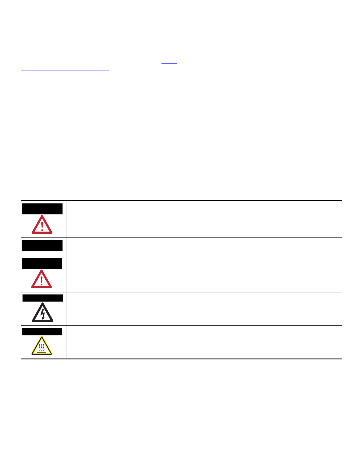
WARNING
IMPORTANT
ATTENTION
SHOCK HAZARD
BURN HAZARD
Solid state equipment has operational characteristics differing from those of electromechanical equipment. Safety Guidelines for the Application,
Installation and Maintenance of Solid State Controls (publication SGI-1.1
http://literature.rockwellautomation.com
) describes some important differences between solid state equipment and hard-wired electromechanical
devices. Because of this difference, and also because of the wide variety of uses for solid state equipment, all persons responsible for applying this
equipment must satisfy themselves that each intended application of this equipment is acceptable.
In no event will Rockwell Automation, Inc. be responsible or liable for indirect or consequential damages resulting from the use or application of this
equipment.
The examples and diagrams in this manual are included solely for illustrative purposes. Because of the many variables and requirements associated
with any particular installation, Rockwell Automation, Inc. cannot assume responsibility or liability for actual use based on the examples and
diagrams.
No patent liability is assumed by Rockwell Automation, Inc. with respect to use of information, circuits, equipment, or software described in this
manual.
Reproduction of the contents of this manual, in whole or in part, without written permission of Rockwell Automation, Inc., is prohibited.
Throughout this manual, when necessary, we use notes to make you aware of safety considerations.
available from your local Rockwell Automation sales office or online at
Identifies information about practices or circumstances that can cause an explosion in a hazardous environment, which may
lead to personal injury or death, property damage, or economic loss.
Identifies information that is critical for successful application and understanding of the product.
Identifies information about practices or circumstances that can lead to: personal injury or death, property damage, or
economic loss. Attentions help you identify a hazard, avoid a hazard, and recognize the consequence.
Labels may be on or inside the equipment, such as a drive or motor, to alert people that dangerous voltage may be present.
Labels may be on or inside the equipment, such as a drive or motor, to alert people that surfaces may reach dangerous
temperatures.
Allen-Bradley, Rockwell Automation, FLEX I/O, RSLinx, RSLogix 5000 and TechConnec t are trademarks of Rockwell Automation, Inc.
Trademarks not belonging to Rockwell Automation are property of their respective companies.
Page 3

Summary of Changes
This manual contains new and updated information. Changes throughout this
revision are marked by change bars, as shown to the right of this paragraph.
New and Updated Information
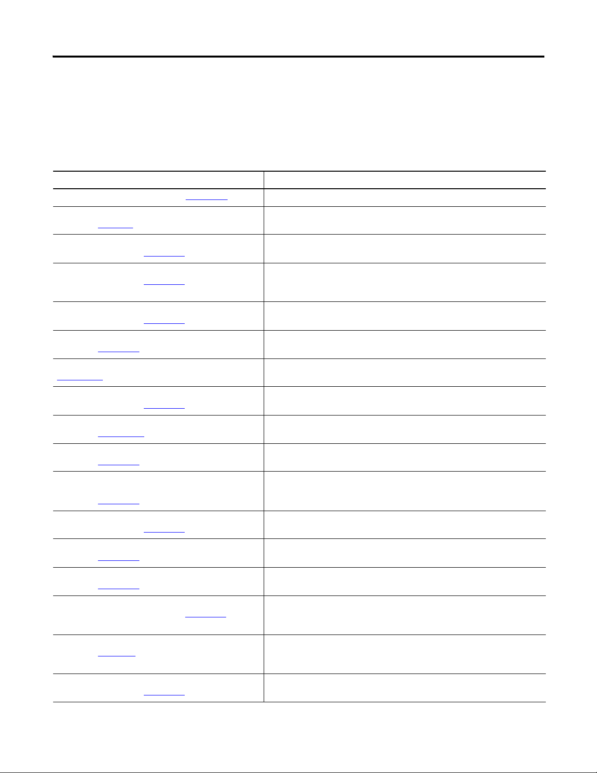
This table contains the changes made to this revision.
Changes Page
Addition of two catalogs – 1794-IRT8K and 1794-IRT8XT 1, 53
The following sections have been added to Chapter 1 – Overview of FLEX I/O
and Your Thermocouple, RTD, and Millivolt Input Module:
1
•The FLEX System
•Types of Modules
•What the FLEX I/O Input Module Does
•The FLEX I/O Module in a Logix Control System
The following section has been added to Chapter 2 – Install Your FLEX I/O Input
Module:
8
•Series A and Series B
The following new topics have been added:
•Configure Your FLEX I/O Module with RSLogix 5000 Software
21
(Chapter 3)
•Troubleshoot the Module (Chapter 6)
•Electronic Data Sheet (EDS) Files (Appendix B)
51
57
The following topic, previously Chapter 3 in the last revision, has been
relegated to the Appendices section:
•Program Your Thermocouple/RTD Input Module (Appendix C)
59
Additional less significant changes (such as improvement of drawings) have
been made throughout the document.
iii Publication 1794-6.5.12 - September 2011
Page 4

iv Summary of Changes
Notes:
Publication 1794-6.5.12 - September 2011
Page 5

Overview of FLEX I/O and Your
Thermocouple, RTD, and
Millivolt Input Module
Table of Contents
Summary of Changes
New and Updated Information. . . . . . . . . . . . . . . . . . . . . . . . . . . . . . . iii
Preface
Who Should Use This Manual. . . . . . . . . . . . . . . . . . . . . . . . . . . . . . . . ix
Purpose of the Manual. . . . . . . . . . . . . . . . . . . . . . . . . . . . . . . . . . . . . . ix
About the Vocabulary . . . . . . . . . . . . . . . . . . . . . . . . . . . . . . . . . . . . . . ix
Related Documentation. . . . . . . . . . . . . . . . . . . . . . . . . . . . . . . . . . . x
Common Techniques Used in this Manual. . . . . . . . . . . . . . . . . . . . . . xii
Chapter 1
Overview. . . . . . . . . . . . . . . . . . . . . . . . . . . . . . . . . . . . . . . . . . . . . . . . . . 1
The FLEX System . . . . . . . . . . . . . . . . . . . . . . . . . . . . . . . . . . . . . . . . . . 1
Types of Modules. . . . . . . . . . . . . . . . . . . . . . . . . . . . . . . . . . . . . . . . . . . 2
What the FLEX I/O Input Module Does . . . . . . . . . . . . . . . . . . . . . . . 2
The FLEX I/O Module in a Logix Control System . . . . . . . . . . . . . . . 3
Physical Features of Your Module . . . . . . . . . . . . . . . . . . . . . . . . . . . . . 4
Chapter Summary. . . . . . . . . . . . . . . . . . . . . . . . . . . . . . . . . . . . . . . . . . . 5
Install Your FLEX I/O Input
Module
Configure Your FLEX I/O
Module with RSLogix 5000
Software
Read and Write Configuration
Maps for the FLEX I/O Module
Chapter 2
Overview. . . . . . . . . . . . . . . . . . . . . . . . . . . . . . . . . . . . . . . . . . . . . . . . . . 7
Before You Install Your Module . . . . . . . . . . . . . . . . . . . . . . . . . . . . . . 7
Series A and Series B . . . . . . . . . . . . . . . . . . . . . . . . . . . . . . . . . . . . . 8
Power Requirements . . . . . . . . . . . . . . . . . . . . . . . . . . . . . . . . . . . . . . . . 8
Install the Module . . . . . . . . . . . . . . . . . . . . . . . . . . . . . . . . . . . . . . . . . 10
Mount on a DIN Rail . . . . . . . . . . . . . . . . . . . . . . . . . . . . . . . . . . . 10
Mount on a Panel or Wall . . . . . . . . . . . . . . . . . . . . . . . . . . . . . . . . 13
Mount the FLEX I/O Module on the Terminal Base Unit . . . . . 14
Wiring Information . . . . . . . . . . . . . . . . . . . . . . . . . . . . . . . . . . . . . . . . 16
Connect Wiring to the FLEX I/O Module . . . . . . . . . . . . . . . . . . 16
Identify RTD Wire Pairs . . . . . . . . . . . . . . . . . . . . . . . . . . . . . . . . . 17
Chapter Summary. . . . . . . . . . . . . . . . . . . . . . . . . . . . . . . . . . . . . . . . . . 20
Chapter 3
Overview. . . . . . . . . . . . . . . . . . . . . . . . . . . . . . . . . . . . . . . . . . . . . . . . . 21
Add and Configure the FLEX I/O Module. . . . . . . . . . . . . . . . . . . . . 21
Chapter Summary. . . . . . . . . . . . . . . . . . . . . . . . . . . . . . . . . . . . . . . . . . 26
Chapter 4
Overview. . . . . . . . . . . . . . . . . . . . . . . . . . . . . . . . . . . . . . . . . . . . . . . . . 27
Configure Your Input Module . . . . . . . . . . . . . . . . . . . . . . . . . . . . . . . 27
Configurable Options and Their Effect on the Channels . . . . . . . . . . 27
Options that Affect All Channels . . . . . . . . . . . . . . . . . . . . . . . . . . 27
Options that Affect Each Group of Four Inputs . . . . . . . . . . . . . 28
Sensor Types. . . . . . . . . . . . . . . . . . . . . . . . . . . . . . . . . . . . . . . . . . . . . . 29
Read Data From the Module. . . . . . . . . . . . . . . . . . . . . . . . . . . . . . . . . 30
v Publication 1794-6.5.12-EN-E - September 2011
Page 6

vi Table of Contents
Map Data for the Module . . . . . . . . . . . . . . . . . . . . . . . . . . . . . . . . . . . 30
Thermocouple and RTD Input Module Image Table
Mapping . . . . . . . . . . . . . . . . . . . . . . . . . . . . . . . . . . . . . . . . . . . 31
Block Transfer Read and Write . . . . . . . . . . . . . . . . . . . . . . . . . . . 31
Bit/Word Descriptions for the Input Module Block Transfer
Read Words . . . . . . . . . . . . . . . . . . . . . . . . . . . . . . . . . . . . . . . . . . . 32
Using Series A Functionality in a
Series B Module . . . . . . . . . . . . . . . . . . . . . . . . . . . . . . . . . . . . . . . . . . . 38
Chapter Summary . . . . . . . . . . . . . . . . . . . . . . . . . . . . . . . . . . . . . . . . . 38
Chapter 5
Calibrate Your Module Overview . . . . . . . . . . . . . . . . . . . . . . . . . . . . . . . . . . . . . . . . . . . . . . . . 39
When and How to Calibrate Your FLEX I/O Module. . . . . . . . . . . . 39
Tools and Equipment . . . . . . . . . . . . . . . . . . . . . . . . . . . . . . . . . . . . . . 40
Calibrate Your Input Module. . . . . . . . . . . . . . . . . . . . . . . . . . . . . . . . 40
Calibration Setup . . . . . . . . . . . . . . . . . . . . . . . . . . . . . . . . . . . . . . 41
Wiring Connections for Calibrating the Thermocouple and
RTD Input Module . . . . . . . . . . . . . . . . . . . . . . . . . . . . . . . . . . . . . 41
Read and Write Words for Calibration. . . . . . . . . . . . . . . . . . . . . . 42
EDT Calibration Command and Command Data Summary . . . . 44
Offset Calibration . . . . . . . . . . . . . . . . . . . . . . . . . . . . . . . . . . . . . . 45
Gain Calibration . . . . . . . . . . . . . . . . . . . . . . . . . . . . . . . . . . . . . . . 46
Current Source Calibration . . . . . . . . . . . . . . . . . . . . . . . . . . . . . . . 47
Cold Junction Calibration . . . . . . . . . . . . . . . . . . . . . . . . . . . . . . . . 49
Channel Loop Compensation Calibration . . . . . . . . . . . . . . . . . . . 49
Chapter Summary . . . . . . . . . . . . . . . . . . . . . . . . . . . . . . . . . . . . . . . . . 49
Chapter 6
Troubleshoot the Module Overview . . . . . . . . . . . . . . . . . . . . . . . . . . . . . . . . . . . . . . . . . . . . . . . . 51
Module Indicators . . . . . . . . . . . . . . . . . . . . . . . . . . . . . . . . . . . . . . . . . 51
Chapter Summary . . . . . . . . . . . . . . . . . . . . . . . . . . . . . . . . . . . . . . . . . 52
Appendix A
Specifications Overview . . . . . . . . . . . . . . . . . . . . . . . . . . . . . . . . . . . . . . . . . . . . . . . . 53
General Specifications. . . . . . . . . . . . . . . . . . . . . . . . . . . . . . . . . . . 53
Environmental Specifications . . . . . . . . . . . . . . . . . . . . . . . . . . . . . 55
Certifications . . . . . . . . . . . . . . . . . . . . . . . . . . . . . . . . . . . . . . . . . . 56
Appendix B
Electronic Data Sheet (EDS)
Files
Publication 1794-6.5.12-EN-E - September 2011
Overview . . . . . . . . . . . . . . . . . . . . . . . . . . . . . . . . . . . . . . . . . . . . . . . . 57
Updating EDS File . . . . . . . . . . . . . . . . . . . . . . . . . . . . . . . . . . . . . 57
EDS Installation . . . . . . . . . . . . . . . . . . . . . . . . . . . . . . . . . . . . . . . 58
Page 7

Table of Contents vii
Appendix C
Programming Your Module
with PLC Family Processors
Overview. . . . . . . . . . . . . . . . . . . . . . . . . . . . . . . . . . . . . . . . . . . . . . . . . 59
Enter Block Transfer Instructions. . . . . . . . . . . . . . . . . . . . . . . . . . . . . 59
PLC-2 Family Processor . . . . . . . . . . . . . . . . . . . . . . . . . . . . . . . . . 60
PLC-3 Family Processor . . . . . . . . . . . . . . . . . . . . . . . . . . . . . . . . . 60
PLC-5 Family Processor . . . . . . . . . . . . . . . . . . . . . . . . . . . . . . . . . 61
PLC-5/250 Family Processor . . . . . . . . . . . . . . . . . . . . . . . . . . . . . 62
Appendix D
Safety Approvals European Hazardous Location Approval. . . . . . . . . . . . . . . . . . . . . . . 65
North American Hazardous Location Approval . . . . . . . . . . . . . . . . . 66
Index
Publication 1794-6.5.12-EN-E - September 2011
Page 8

viii Table of Contents
Notes:
Publication 1794-6.5.12-EN-E - September 2011
Page 9

Preface
Read this preface to familiarize yourself with the rest of the manual. It provides
information concerning:
• who should use this manual
• the purpose of this manual
• related documentation
• conventions used in this manual
• terminology used in this manual
Who Should Use This Manual
Purpose of the Manual
We assume that you have previously used an Allen-Bradley programmable
controller, that you are familiar with its features, and that you are familiar with
the terminology we use. If not, read the user manual for your processor before
reading this manual.
This manual is a reference guide for the FLEX I/O Thermocouple, RTD,
Millivolt Input Modules. It describes the procedures for installing, configuring
and troubleshooting your module. For more information, consult the
following chapters.
Topic See
Overview of FLEX I/O and Your Thermocouple, RTD, and Millivolt Input Module Chapter 1
Install Your FLEX I/O Input Module Chapter 2
Configure Your FLEX I/O Module with RSLogix 5000 Software Chapter 3
Read and Write Configuration Maps for the FLEX I/O Module Chapter 4
Calibrate Your Module Chapter 5
Troubleshoot the Module Chapter 6
Specifications Appendix A
Electronic Data Sheet (EDS) Files Appendix B
Programming Your Module with PLC Family Processors Appendix C
Safety Approvals A
ppendix D
About the Vocabulary
ix Publication 1794-6.5.12 - September 2011
This manual covers the 1794-IRT8, 1794-IRT8K, and 1794-IRT8XT modules,
which are identical, except that the 1794-IRT8K is conformally coated.
In this manual, we refer to:
• the individual Thermocouple, RTD, and mV module as the “module,”
or “TC, RTD, and mV module.”
• the programmable controller as the “controller” or the “processor.”
Page 10
x Preface
Related Documentation
The following documents contain additional information about Rockwell
Automation products. To obtain a copy, contact your local
Rockwell Automation office or distributor.
Resource Description
FLEX I/O Product Profile, publication 1794-PP019
FLEX I/O ControlNet Redundant Media Adapter,
publication 1794-5.18
FLEX I/O EtherNet/IP Adapter Module Installation
Instructions, publication 1794-IN082
FLEX I/O ControlNet Adapter Module Installation
Instructions, publication 1794-IN128
FLEX I/O DeviceNet Adapter Module Installation
Instructions, publication 1794-IN099
Remote I/O Adapter Modules Installation Instructions,
publication 1794-IN098
Remote I/O Adapter Module User Manual, publication
1794-UM009
FLEX I/O PROFIBUS Adapter Module Installation
Instructions, publication 1794-IN087
FLEX I/O PROFIBUS Adapter Module User Manual,
publication 1794-UM057
Flex I/O Digital Input Modules Installation Instructions,
publication 1794-IN093
Flex I/O Digital DC Sourcing Input and Sinking Output
Modules Installation Instructions,
publication 1794-IN095
x xxxxxxxxxxxxx
x xxxx
x xxxx
x xxxx
x xxxxxxxxxxxxx
x xxxxxxxxxxxxx
x xxxxxxxxxxxxx
x xxxxxxxxxxxxx
x xxxxxxxxxxxxx
x xxxxxxxxxxxxx
xxxxx Comprehensive product profile for the FLEX I/O product line.
Information on how to install the FLEX I/O ControlNet Redundant Media
Adapter (1794-ACNR).
Information on how to install the FLEX I/O EtherNet/IP Adapter Module
(Catalog No. 1794-AENT).
Information on how to install the ControlNet Adapter Modules
(Catalog No. 1794-ACN15, 1794-ACN15K, 1794-ACNR15, 1794-ACNR15XT,
Series D).
Information on how to install the FLEX I/O DeviceNet Adapter Modules
(Catalog No. 1794-ADN, 1794-ADNK).
Information on how to install the Remote I/O Adapter Modules
(Catalog No. 1794-ASB, 1794-ASB2, 1794-ASBK, 1794-ASB2K).
Information on how to use the Remote I/O Adapter Module
(Catalog No. 1794-ASB).
Information on how to install the FLEX I/O PROFIBUS Adapter
(Catalog No. 1794-APB).
Information on how to use the FLEX I/O PROFIBUS Adapter Module
(Catalog No. 1794-APB).
Information on how to install the Flex I/O Digital Input Modules
(Catalog No. 1794-IB8, 1794-IB16, 1794-IB16K, 1794-IB32).
Information on how to install the Flex I/O Digital DC Sourcing Input and
Sinking Output Modules (Catalog No. 1794-IV16, 1794-OV16, 1794-OV16P).
Flex I/O Digital DC Sourcing Output Modules Installation
Instructions, publication 1794-IN094
Flex I/O Input/ Output Module Installation Instructions,
publication 1794-IN083
Flex I/O 8 Output Relay Module Installation Instructions,
publication 1794-IN019
FLEX I/O Input, Output and Input/Output Analog Modules
Installation Instructions, publication 1794-IN100
FLEX I/O Analog Module User Manual,
publication 1794-6.5.2
FLEX I/O Isolated Analog Output Module Installation
Instructions, publication 1794-IN037
Publication 1794-6.5.12 - September 2011
x xxxxxxxxxxxxx
x xxxxxxxxxxxxx
x xxxxxxxxxxxxx
x xxxxxxxxxxxxx
xxxxxxx
x xxxxxxxxxxxxx
Information on how to install the Flex I/O Digital DC Sourcing Output Modules
(Catalog No. 1794-OB8, 1794-OB8EP, 1794-OB16, 1794-OB16P, 1794-OB32P).
Information on how to install the Flex I/O Input/ Output Modules
(Catalog No. 1794-IB16XOB16P, 1794-IB10XOB6).
Information on how to install the Flex I/O 8 Output Relay Modules
(Catalog No. 1794-OW8, 1794-OW8K, 1794-OW8XT).
Information on how to install the FLEX I/O Input, Output and Input/Output
Analog Modules (Catalog No. 1794-IE8, 1794-IE4XOE2, 1794-OE4, 1794-IE8K,
1794-OE4K).
Information on how to install the FLEX I/O Analog Modules
(Catalog No. 794-OE4, 1794-IE8, 1794-IE12, 1794-OE12, 1794-IE4XOE2,
1794-IE8XOE4, 1794-IE4XOE2XT, 1794-IE8XT, 1794-OE4XT).
Information on how to install the FLEX I/O Isolated Analog Output Module
(Catalog No. 1794-OF4I).
Page 11

Resource Description
Preface xi
FLEX I/O 4 Isolated Input Module Installation Instructions,
publication 1794-IN038
x xxxxxxxxxxxxx
FLEX I/O 2 In/2 Out Isolated Analog Combo Module
Installation Instructions, publication 1794-IN039
x
xxxxxxxxxxxxx
FLEX I/O Isolated Analog Modules User Manual,
publication 1794-6.5.8
x xxxxxxxxxxxxx
FLEX I/O 8 Thermocouple Input Module Installation
Instructions, publication 1794-IN021
x xxxxxxxxxxxxx
FLEX I/O 8 Input RTD Module User Manual,
publication 1794-6.5.4
x xxxxxxxxxxxxx
FLEX I/O Thermocouple/Millivolt Input Module User
Manual, publication 1794-6.5.7
x xxxxxxxxxxxxx
FLEX I/O Thermocouple/RTD Input Analog Module
Instructions, publication 1794-IN050
x xxxxxxxxxxxxx
2-Input Frequency Module Installation Instructions,
publication 1794-IN049
x xxxxxxxxxxxxx
FLEX I/O Frequency Input Module User Manual,
publication 1794-6.5.11
x xxxxxxxxxxxxx
24V FLEX I/O 2 Channel Incremental Encoder Module
Installation Instructions, publication 1794-IN063
x
xxxxxxxxxxxxx
Information on how to install the FLEX I/O 4 Isolated Input Module
(Catalog No. 1794-IF4I).
Information on how to install the FLEX I/O 2 In/2 Out Isolated Analog Combo
Module (Catalog No. 1794-IF2XOF2I).
Information on how to use the FLEX I/O Isolated Analog Modules
(Catalog No. 1794-IF4I, 1794-OF4I, 1794-IF2XOF2I, 1794-IF4IXT, 1794-IF4ICFXT,
1794-OF4IXT, 1794-IF2XOF2IXT).
Information on how to install the FLEX I/O 8 Thermocouple Input Modules
(Catalog No. 1794-IT8, 1794-IR8).
Information on how to use the FLEX I/O 8 Input RTD Module
(Catalog No. 1794-IR8).
Information on how to use the Thermocouple and Millivolt Input Module
(Catalog No. 1794-IT8).
Information on how to install the Thermocouple/Millivolt Input Modules
(Catalog No. 1794-IRT8, 1794-IRT8K, 1794-IRT8XT).
Information on how to install the 2-Input Frequency Module
(Catalog No. 1794-IJ2, 1794-IJ2K, 1794-IJ2XT).
Information on how to use the FLEX I/O Frequency Input Module
(Catalog No. 1794-IJ2).
Information on how to install the 24V FLEX I/O 2 Channel Incremental Encoder
Module (Catalog No. 1794-ID2).
FLEX Integra Analog Module User Manual,
publication 1793-6.5.1
x xxxxxxxxxxxxx
FLEX I/O 4 Channel Pulse Counter Module Installation
Instructions, publication 1794-IN064
x xxxxxxxxxxxxx
FLEX I/O Very High Speed Counter Module Installation
Instruction, publication 1794-IN067
x xxxxxxxxxxxxx
FLEX I/O 48V DC Input and Output Modules Installation
Instructions, publication 1794-IN105
x xxxxxxxxxxxxx
FLEX I/O AC Digital Input Modules Installation
Instructions, publication 1794-IN102
x xxxxxxxxxxxxx
FLEX I/O Digital AC Output Modules Installation
Instructions, publication 1794-IN103
x xxxxxxxxxxxxx
FLEX I/O 220V AC Input and Output Modules Installation
Instructions, publication 1794-IN104
x xxxxxxxxxxxxx
FLEX I/O Terminal Base Units Installation Instructions,
publication 1794-IN092
x xxxxxxxxxxxxx
Interconnect Cable Installation Instructions,
publication 1794-5.12
x xxxxxxxxxxxxx
Information on how to install the FLEX Integra Analog Module (Catalog No.
1793-IE2X0E1,1793-IE2XOE1S, 1793-IE4, 1793-IE4S, 1793-OE2, 1793-OE2S).
Information on how to install the 24V DC FLEX I/O 4-Channel Module
(Catalog No. 1794-IP4).
Information on how to install the Very High Speed Counter Module
(Catalog No. 1794-VHSC).
Information on how to install the FLEX I/O 48V DC Input and Output Modules
(Catalog No. 1794-IC16, 1794-OC16).
Information on how to install the FLEX I/O AC Input Modules
(Catalog No. 1794-IA8, 1794-IA8I, 1794-IA16).
Information on how to install the FLEX I/O Digital AC Output Modules
(Catalog No. 1794-OA8, 1794-OA8K, 1794-OA8I, 1794-OA16).
Information on how to install the FLEX I/O 220V AC Input and Output Modules
(Catalog No. 1794-IM8, 1794-OM8).
Information on how to install the FLEX I/O Terminal Base Units
(Catalog No. 1794-TB2, 1794-TB3, 1794-TB3K, 1794-TB3S, 1794-TB32,
1794-TB3G, 1794-TB3GK, 1794-TB3GS, 1794-TB3T, 1794-TB3TS, 1794-TBN,
1794-TBNK, 1794-TBNF).
Information on how to install the Interconnect Cable
(Catalog No. 1794-CE1, 1794-CE3).
Publication 1794-6.5.12 - September 2011
Page 12

xii Preface
Resource Description
FLEX I/O DC Power Supply Installation Instructions,
publication 1794-IN069
Industrial Automation Wiring and Grounding Guidelines,
publication 1770-4.1
Rockwell Automation Industrial Automation Glossary,
AG-7.1
x xxxxxxxxxxxxx
Common Techniques Used in this Manual
x xxxxxxxxxxxxx
x xxxxxxxxxxxxx
The following conventions are used throughout this manual:
• Bulleted lists such as this one provide information, not procedural steps.
• Numbered lists provide sequential steps or hierarchical information.
• Italic type is used for emphasis.
Information on how to install the FLEX I/O DC Power Supply
(Catalog No. 1794-PS13, 1794-PS3).
In-depth information on grounding and wiring Allen-Bradley programmable
controllers.
A glossary of industrial automation terms and abbreviations.
Publication 1794-6.5.12 - September 2011
Page 13
Chapter
I/O moduleTerminal baseAdapter
1794-IRT8
2
+
2
+
45374
1
Overview of FLEX I/O and Your Thermocouple,
RTD, and Millivolt Input Module
Overview
The FLEX System
This chapter provides a description of the FLEX I/O Thermocouple, RTD,
and Millivolt Input module and an overview of how it communicates with
programmable controllers.
Topic Page
The FLEX System 1
Types of Modules 2
What the FLEX I/O Input Module Does 2
The FLEX I/O Module in a Logix Control System 3
Physical Features of Your Module 4
Chapter Summary 5
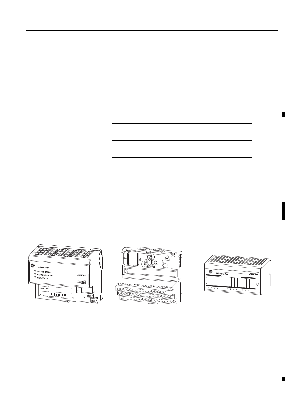
FLEX I/O is a small, modular I/O system for distributed applications that
performs all of the functions of rack-based I/O. The FLEX system contains
the following components shown below:
• Adapter – transfers read and write configuration data to and from the
I/O module
• Terminal base – contains a terminal strip to terminate wiring for two- or
three-wire devices
• I/O module – contains the bus interface and circuitry needed to
perform specific functions related to your application
1 Publication 1794-6.5.12 - September 2011
Page 14

2 Overview of FLEX I/O and Your Thermocouple, RTD, and Millivolt Input Module
The FLEX system consists of an adapter module, terminal base unit, DIN rail,
power supply, and adapter cabling components. You can use up to 8 terminal
bases per adapter module.
For detailed instructions on how to set up and install your module, refer to the
topic, Install Your FLEX I/O Input Module, on page 7.
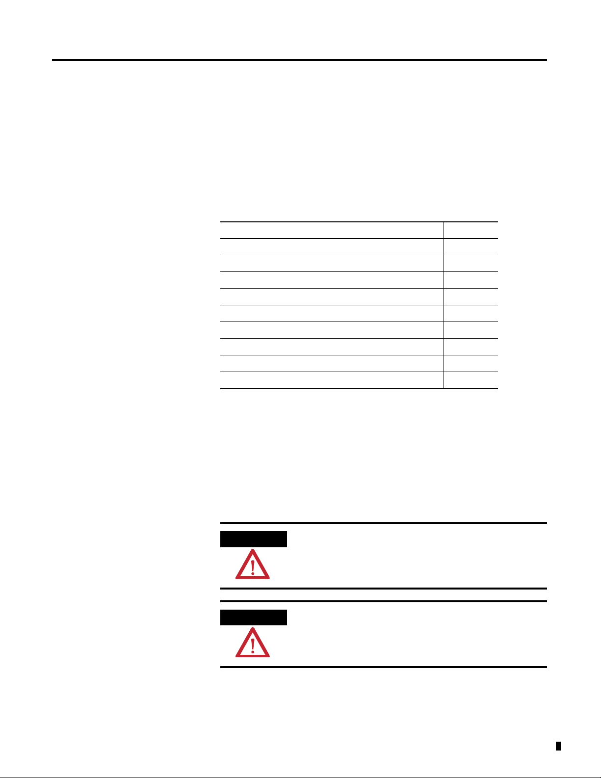
Types of Modules
What the FLEX I/O Input Module Does
The module refer to the following catalogs.
Catalog No. Voltage Inputs Description
1794-IRT8 24V DC 8 Analog – 8-pt, 16 bit non-isolated RTD,
thermocouple and mV Input module
1794-IRT8K 24V DC 8 Analog – 8-pt, 16 bit non-isolated RTD,
thermocouple and mV Input module.
Conformally coated module.
1794-IRT8XT 24V DC 8 Analog – 8-pt, 16 bit non-isolated RTD,
thermocouple and mV Input module designed
for extended temperature.
The module accepts up to 8 thermocouple or RTD inputs. The inputs are
nonisolated and are selected with analog multiplexers. The inputs accept
millivolt or resistive inputs. Default input spans are -40.00 mV… +100.00 mV
or 0.0…500.0 Ω. Fault indicators are located on the field side.
No switches or jumpers are used on the TC and RTD Input module. The
inputs have both fixed hardware filters and selectable firmware digital filters.
The module is a high-speed, high-accuracy temperature and millivolt
measuring module that accepts thermocouple inputs, 2-, 3-, and 4-wire RTD
inputs, and mV source inputs.
Publication 1794-6.5.12 - September 2011
It offers the following:
• wire-off, over-range, and under-range detection
• good common mode rejection
• usage with long thermocouple wiring
• usage with grounded or ungrounded thermocouples
The Series B version of 1794-IRT8 provides capability to work with grounded
thermocouples.
Use cold junction compensators (cat. no. 1794-CJC2) in thermocouple mode.
Two cold junction compensators are shipped with the 1794-IRT8.
Page 15
Overview of FLEX I/O and Your Thermocouple, RTD, and Millivolt Input Module 3
IN 0 IN 2 IN 4 IN 6IN 1 IN 3 IN 5 IN 7
TC RTD INPUT 8 CHANNEL
3
1794-IRT8
PWR
FF F FF F F F
45316
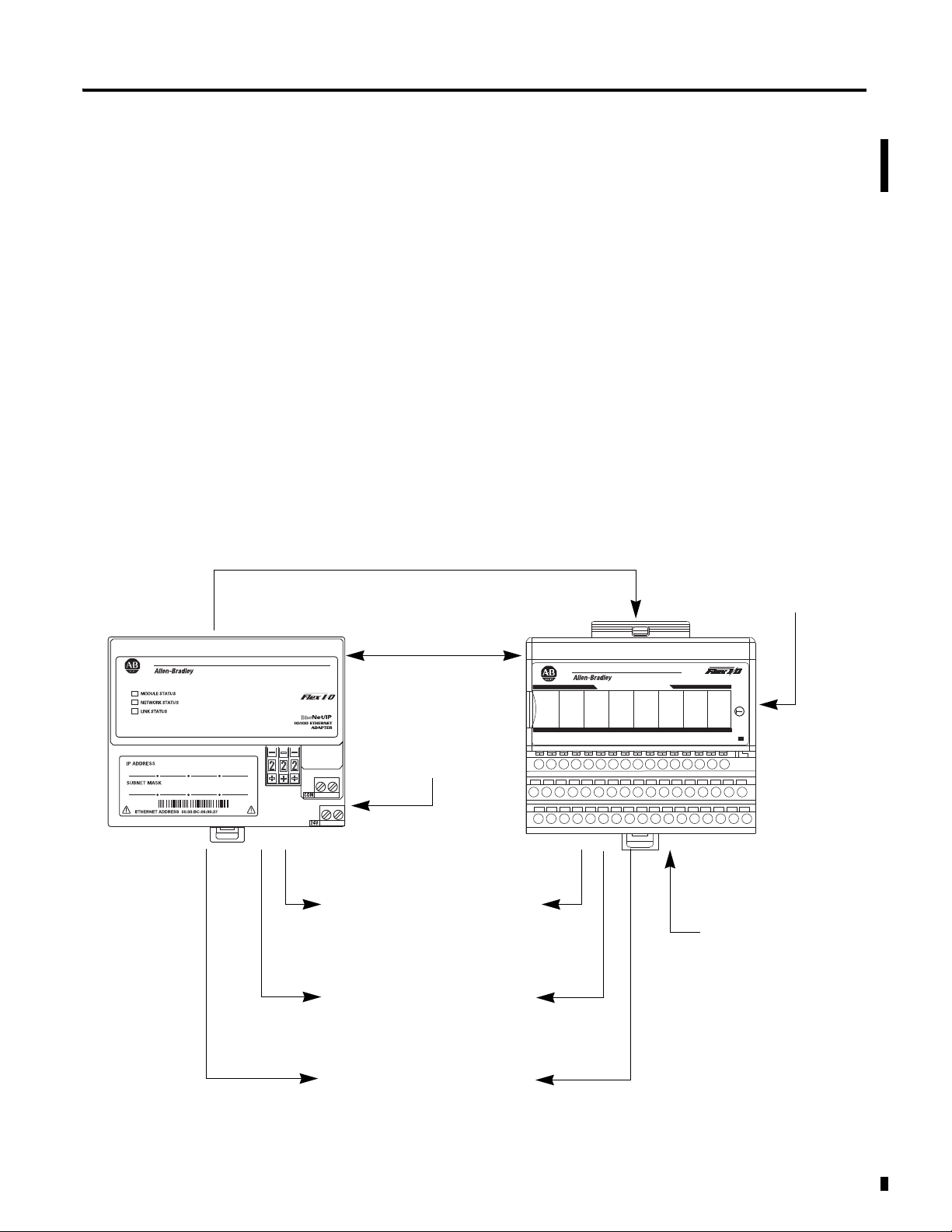
The adapter transfers your configuration data.
FlexBus
External devices transmit
analog signals to the
module.
The module converts
analog signals into binary
format and stores these
values until the adapter
requests their transfer.
The adapter receives data
from the modules and stores
it in the data table.
The adapter module determines that the
transfer was made without error and
input values are within specified range.
Your ladder program can use and/or
move the data (if valid) before it is
overwritten by the transfer of new data
in a subsequent transfer.
1
4
5
6
2
3
New configuration data can be sent to
the module any time during operation.
7
1794-ACN15
1794-ACNR15
1794-ACNR15K
1794-ADN
1794-AENT
1794-APBDPV1
1794-ASB
1794-APB
Adapter
1794-AENT shown
The FLEX I/O Module in a Logix Control System
The FLEX I/O Thermocouple, RTD, and Millivolt modules are intelligent
modules that interface analog signals with Rockwell Automation
programmable controllers through a FLEX I/O adapter module.
The adapter transfers data to and from the module. These transfers allow:
• the adapter to obtain input or output values and status from the module
• the user to establish the mode of operation through a process called
configuration
The following illustration shows the flow of communication between the
adapter and the I/O module.
Typical Communication Between the Adapter and a Module
Publication 1794-6.5.12 - September 2011
Page 16
4 Overview of FLEX I/O and Your Thermocouple, RTD, and Millivolt Input Module
45567
ATTENTION
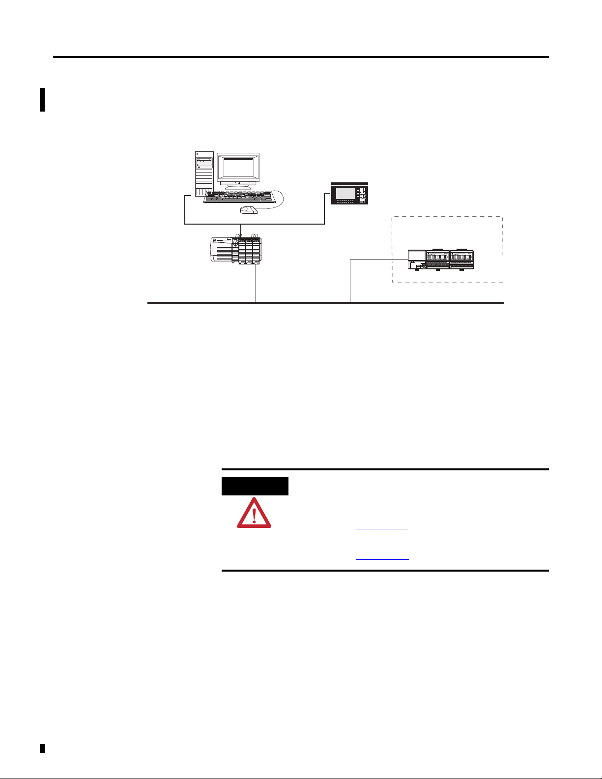
A broader view of how the FLEX I/O module interfaces with the different
elements in a Logix system is shown in the sample illustration below.
PC running
controller and
Rockwell Automation
configuration software
Bridge
Ethernet
In this example, the FLEX I/O module communicates with the controller
through the adapter. The controller can produce and consume tags. It can
initiate MSG instructions that send and receive data or configure devices.
Configuration of devices and the network is done through the personal
computer running the controller and configuration software.
PanelView Station
FLEX System
1794 adapter
1794 FLEX I/O module
Physical Features of Your Module
To learn the prerequisites and steps to configure your FLEX I/O module
using RSLogix 5000 software, see Configure Your FLEX I/O Module with
RSLogix 5000 Software on page 21.
.
The following publications provide more information about
EtherNet/IP, and ControlNet modules in a Logix5000 system:
•EtherNet/IP Modules in Logix5000 Control Systems,
publication ENET-UM001
•ControlNet Modules in Logix5000 Control Systems,
publication CNET-UM001
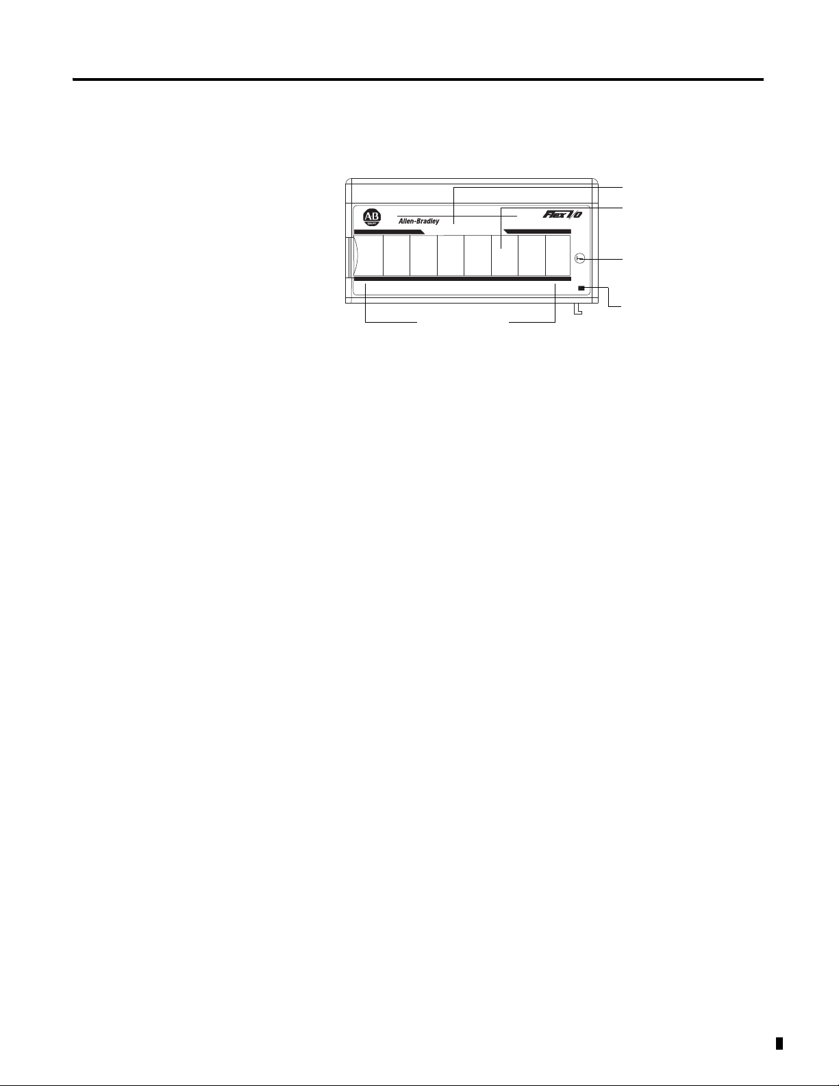
The module label identifies the keyswitch position, wiring and module type. A
removable label provides space for writing individual designations per your
application. Indicators are provided to identify input fault conditions, and to
show when power is applied to the module.
Publication 1794-6.5.12 - September 2011
Page 17
Overview of FLEX I/O and Your Thermocouple, RTD, and Millivolt Input Module 5
IN 0 IN 2 IN 4 IN 6IN 1 IN 3 IN 5 IN 7
TC RTD INPUT 8 CHANNEL
3
1794-IRT8
PWR
FF F FF F F F
1794-IRT8
Input designators
Module type
Removable label
Keyswitch
position indicator (#3)
Power on indicator
45317
Module Label and Indicators
Chapter Summary
In this chapter, you were introduced to the FLEX I/O system and the
Thermocouple, RTD, and mV input module, and how it communicates with
programmable controllers.
Publication 1794-6.5.12 - September 2011
Page 18

6 Overview of FLEX I/O and Your Thermocouple, RTD, and Millivolt Input Module
Notes:
Publication 1794-6.5.12 - September 2011
Page 19
Install Your FLEX I/O Input Module
ATTENTION
ATTENTION
Chapter
2
Overview
Before You Install Your Module
This chapter provides you with pre-installation requirements and instructions
on how to install your FLEX I/O Thermocouple, RTD, and Millivolt Input
module.
Topic Page
Before You Install Your Module 7
Series A and Series B 8
Power Requirements 8
Install the Module 10
Mount on a DIN Rail 10
Mount on a Panel or Wall 13
Mount the FLEX I/O Module on the Terminal Base Unit 14
Wiring Information 16
Chapter Summary 20
Before installing your FLEX I/O Thermocouple, RTD, and mV module, you
need to:
• verify that a suitable enclosure is available for installation of the module,
and
• position the keyswitch on the terminal base.
These modules do not receive primary operational power from the
backplane. 24V DC power must be applied to your module before
installation. If power is not applied, the module position may appear
to the adapter as an empty slot in your chassis.
If using a Series B product to replace a Series A product, connect a
wire between terminals 39 and 48 on the 1794-TB3G or 1794-TB3GS
terminal base unit. If not connected, the Series B product defaults to
Series B functionality.
7 Publication 1794-6.5.12 - September 2011
Page 20
8 Install Your FLEX I/O Input Module
ATTENTION
ATTENTION
ATTENTION
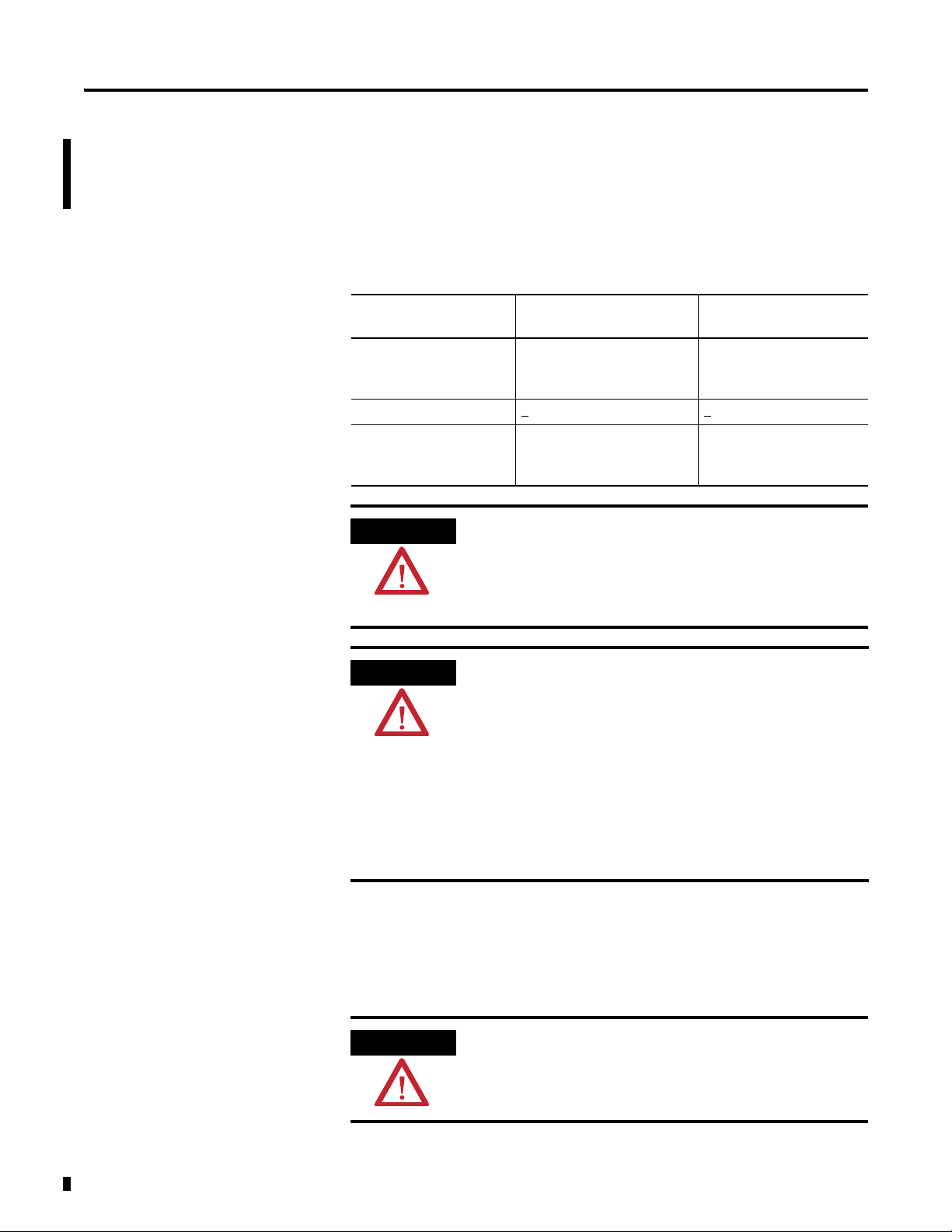
Series A and Series B
The table, Series A and Series B Differences, describes the differences between
Series A and Series B of the FLEX I/O Thermocouple, RTD, and mV Input
modules.
Series A and Series B Differences
Mode 1794-IRT8 Series A 1794-IRT8, 1794-IRT8XT
Series B
Isolation Between user side and
system side
Common Mode Range +
Thermocouple Mode
Wire-off Detection
In the RSLogix 5000 software, if using a series B product to replace a
series A product, the module will be accepted without an electronic
key mismatch warning.
This is true for 1794-IRT8 and 1794-IRT8XT modules installed on
Ethernet/IP, ControlNet, or Remote I/O networks.
The CJC Status bit, Read Word 9, Bit 3 is added with the Firmware C
release of the 1794-IRT8 Series B module.
The CJC Status bit is turned On when the temperature between the
CJCs is greater than 6 °C but less than 12 °C.
When this temperature difference is above 12 °C, then the CJC Alarm
bits are set.
Also, if a CJC temperrature is over-range or under-range, then the
associated CJC Alarm bit is set. In this condition, the CJC Status bit is
not set.
The CJC Status bit did not exist in Series A.
4V DC +15V DC
When an open sensor is
detected, data defaults to
maximum value
Between user 24V DC and
user I/O; between user side
and system side
When open sensor is
detected, data defaults to
minimum value
Power Requirements
Publication 1794-6.5.12 - September 2011
The wiring of the terminal base unit is determined by the current draw
through the terminal base. Make certain that the current draw does not
exceed 10 A.
Total current draw through the terminal base unit is limited to 10 A.
Separate power connections may be necessary.
Page 21
Install Your FLEX I/O Input Module 9
ATTENTION
Digital Input
Module
Analog
Module
Analog
Module
Analog
Module
Digital Output
Module
Digital Input
Module
TC/RTD/mV
Module
Analog
Module
TC/RTD/mV
Module
TC/RTD/mV
Module
TC/RTD/mV
Module
TC/RTD/mV
Module
Daisychain
Individual
Combination
24V DC
24V DC
24V DC
24V DC
24V DC
24V DC
45318
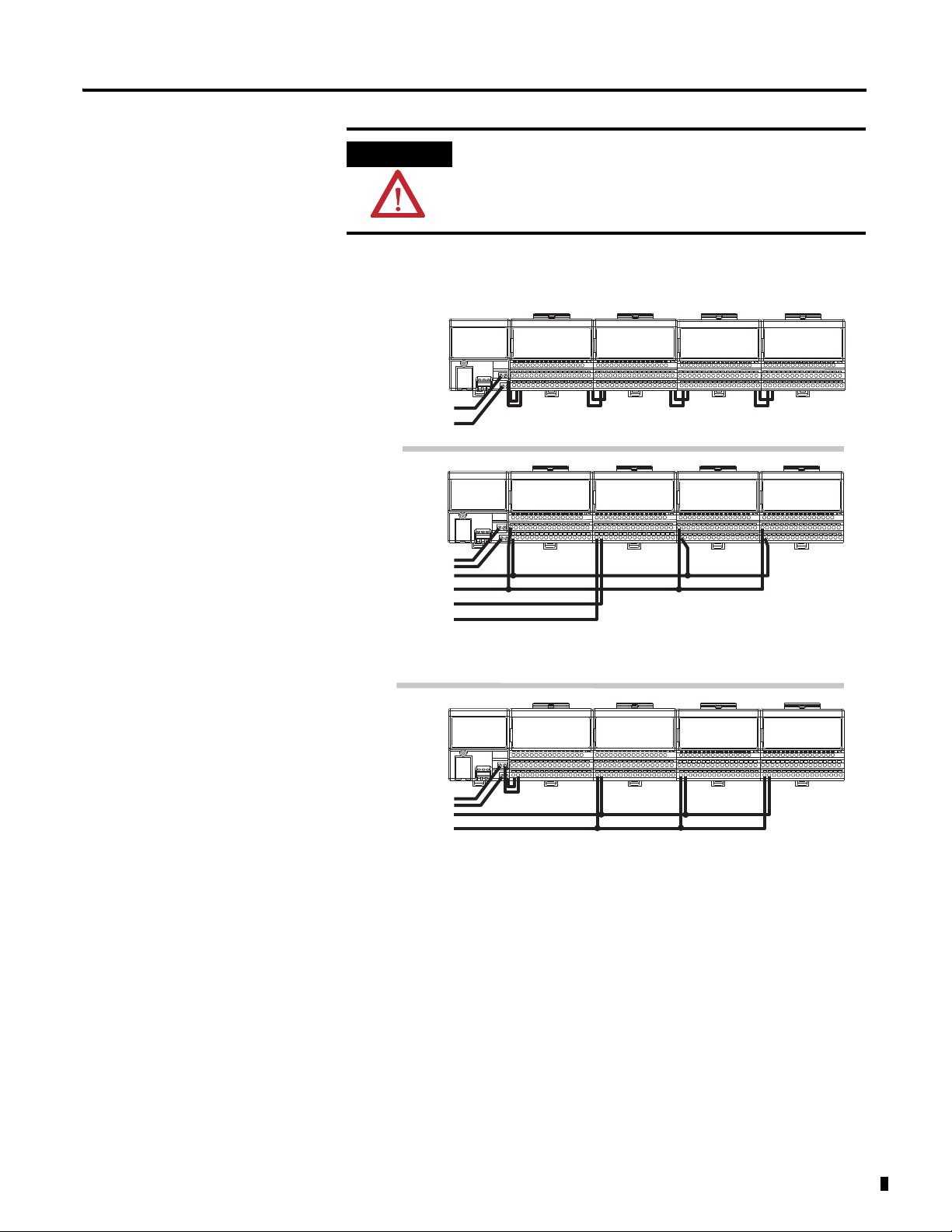
Wiring when total current draw is less than 10 A
Wiring when total current draw is less than 10 A
Thermocouple, RTD, Millivolt wiring separate from digital wiring.
Total current draw through any base unit must not be greater than 10 A
Do not daisychain power or ground from the terminal base unit to any
AC or DC digital module terminal base unit.
Methods of wiring the terminal base units are shown in the illustration below.
Publication 1794-6.5.12 - September 2011
Page 22
10 Install Your FLEX I/O Input Module
ATTENTION
ATTENTION
Note the following considerations for each type of wiring
configuration:
• Daisychain – AIl modules must be analog or TC, RTD, and mV
modules for this configuration.
• Individual – Use this type of of configuration for any "noisy" DC
digital I/O modules in your system.
• Combination – All modules powered by the same power supply
must be analog or TC, RTD, and mV modules for the combination
type of configuration.
Install the Module
Installation of the FLEX I/O module consists of:
• mounting the terminal base unit
• installing the TC, RTD, and mV module into the terminal base unit
• installing the connecting wiring to the terminal base unit
If you are installing your module into a terminal base unit that is already
installed, proceed to the section, Mount the FLEX I/O Module on the
Terminal Base Unit, on page 14.
Mount on a DIN Rail
Do not remove or replace a terminal base unit when power is applied.
Interruption of the FlexBus can result in unintended operation or
machine motion.
Install the Terminal Base Unit
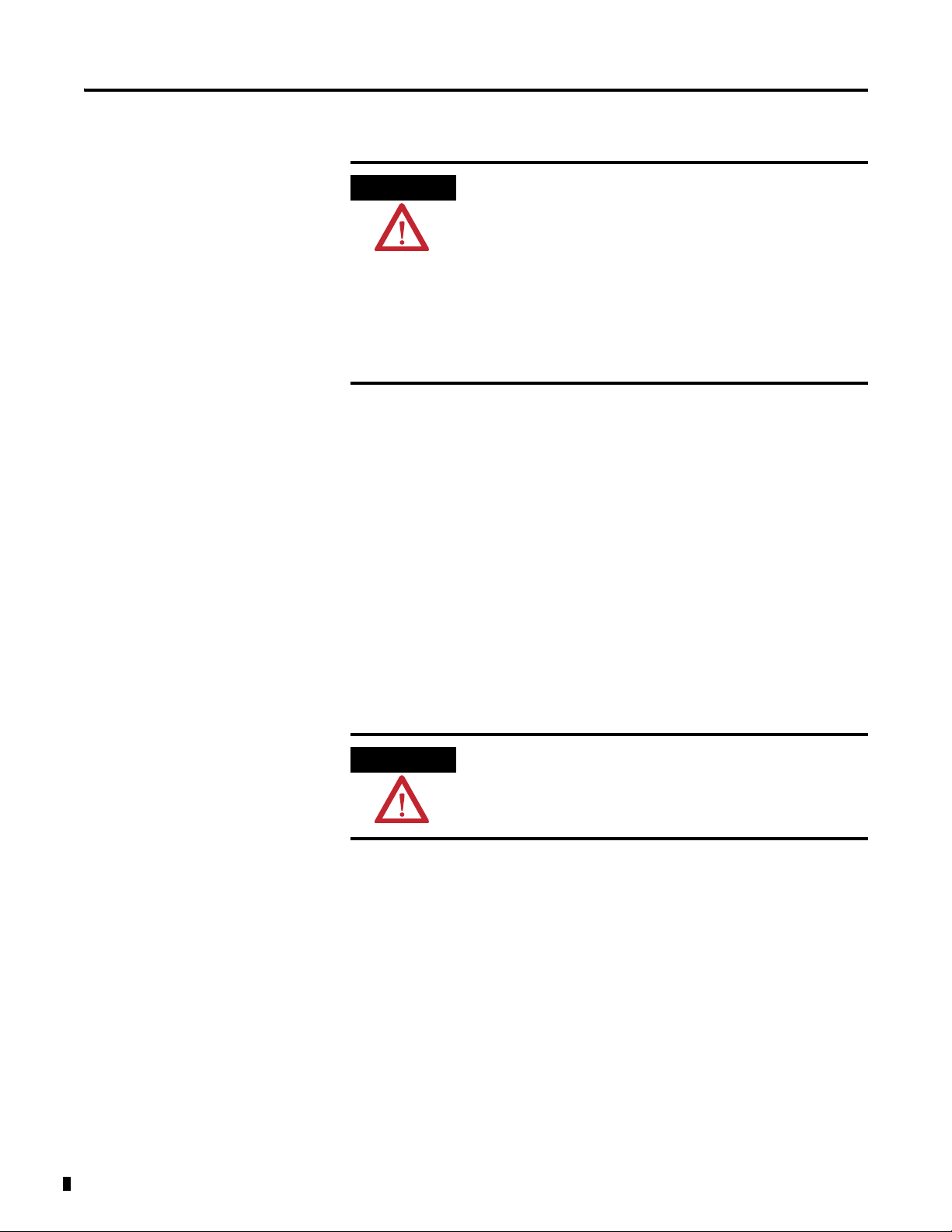
1. Remove the cover plug in the male connector of the unit to which you
are connecting this terminal base unit.
Publication 1794-6.5.12 - September 2011
Page 23
Install Your FLEX I/O Input Module 11
1
2
3
4
6
7
7
8
9
0
2
+
2
+
45319
2
+
2
+
45320
2. Check to make sure that the 16 pins in the male connector on the
adjacent device are straight and in line so that the mating female
connector on this terminal base unit will mate correctly.
Make certain that the female FlexBus connector is fully retracted into
the base unit.
3. Position the terminal base at a slight angle and hooked over the top of
the 35 x 7.5 mm DIN rail A (Allen-Bradley part number 199-DR1;
46277-3).
4. Slide the terminal base over tight against the adapter, or proceeding
terminal base. Make sure the hook on the terminal base slides under the
edge of the adapter, or proceeding terminal base, and the FlexBus
connector is fully retracted.
Publication 1794-6.5.12 - September 2011
Page 24
12 Install Your FLEX I/O Input Module
2
+
2
+
45321
2
+
2
+
45322
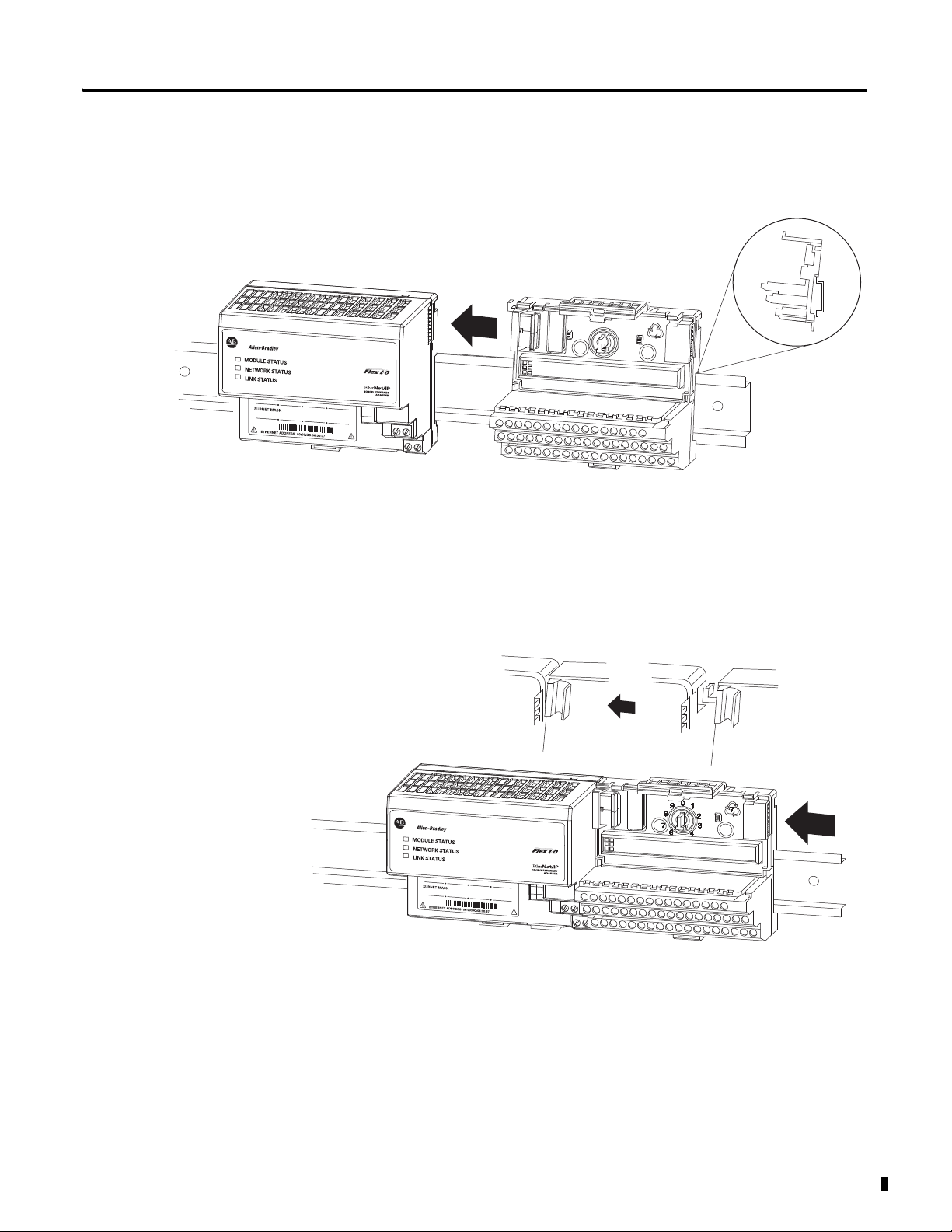
5. Rotate the terminal base onto the DIN rail with the top of the rail
hooked under the lip on the rear of the terminal base.
Use caution to make sure that the female FlexBus connector does not
strike any of the pins in the mating male connector.
6. Press down on the terminal base unit to lock the terminal base on the
DIN rail. If the terminal base does not lock into place, use a screwdriver
or similar device to open the locking tab, press down on the terminal
base until flush with the DIN rail and release the locking tab to lock the
base in place.
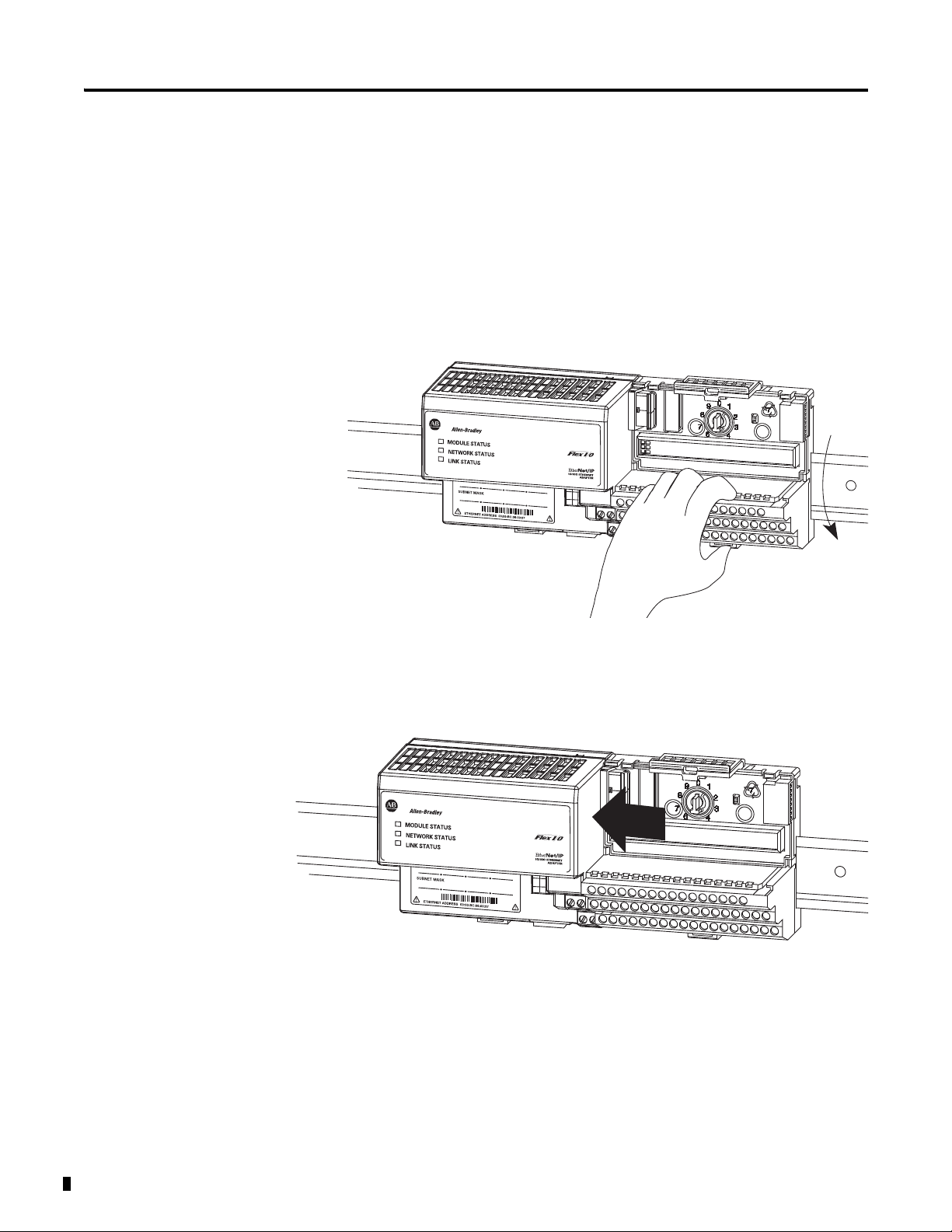
Gently push the FlexBus connector into the side of the adapter, or
proceeding terminal base, to complete the backplane connection.
For specific wiring information, refer to the installation instructions for
the module you are installing in this terminal base unit.
7. Repeat the above steps to install the next terminal base unit.
Ensure that the cover of the FlexBus connector on the last terminal
base unit is in place.
Publication 1794-6.5.12 - September 2011
Page 25
Install Your FLEX I/O Input Module 13
1
2
3
4
45323
Millimeters
(Inches)
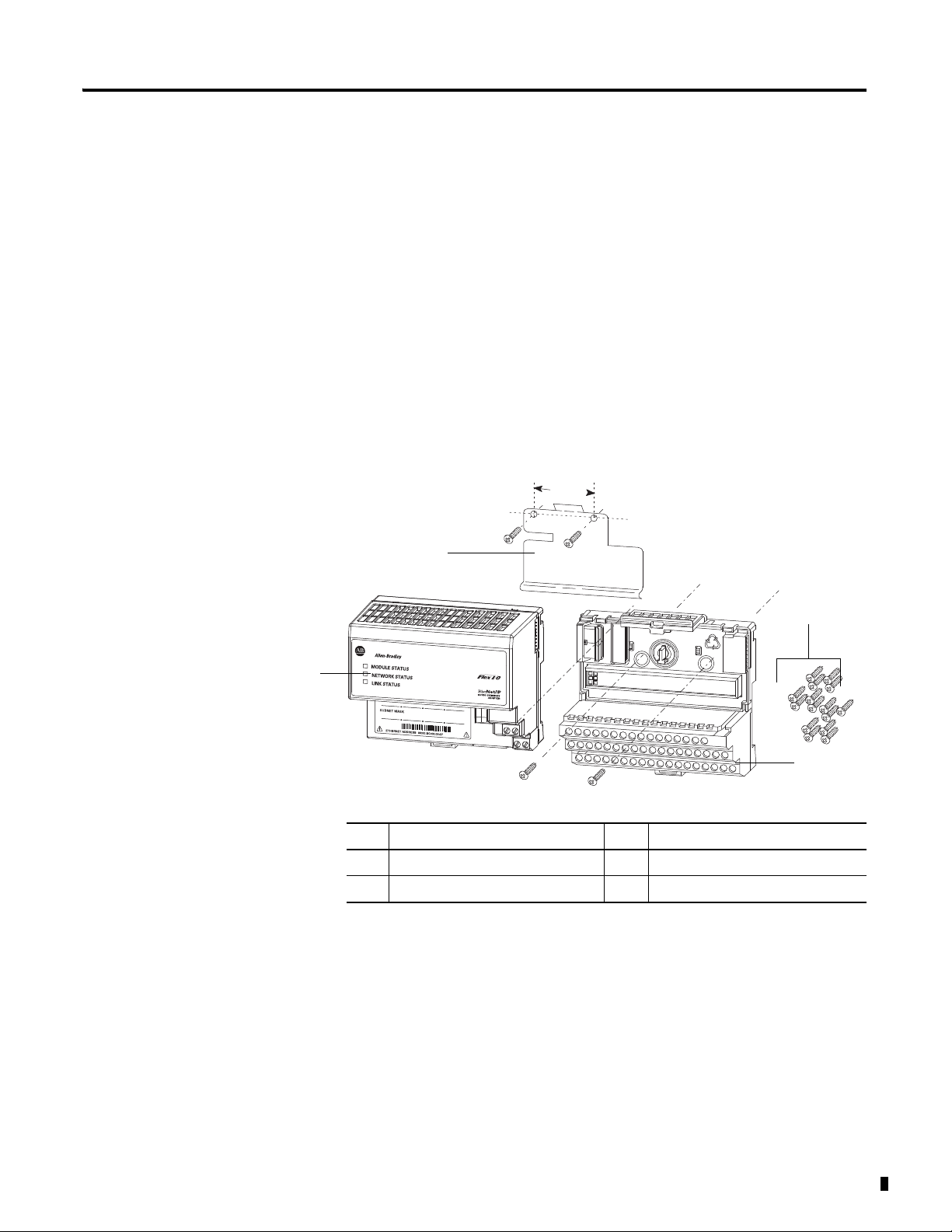
Mount on a Panel or Wall
Installation of a FLEX system on a wall or panel consists of:
• laying out the drilling points on the wall or panel.
• drilling the pilot holes for the mounting screws.
• mounting the adapter mounting plate.
• installing the terminal base units and securing them to the wall or panel.
If you are installing your module into a terminal base unit that is already
installed, proceed to the section, Mount the FLEX I/O Module on the
Terminal Base Unit, on page 14.
Use the mounting kit Cat. No. 1794-NM1 for panel or wall mounting.
35.5
(1.4)
0
9
1
8
7
6
2
2
+
+
7
2
3
4
Description Description
1 Mounting plate for adapter 3 Terminal base unit (not included)
2 #6 Self-tapping screws 4 Adapter module (not included)
To install the mounting plate on a wall or panel:
Publication 1794-6.5.12 - September 2011
Page 26
14 Install Your FLEX I/O Input Module
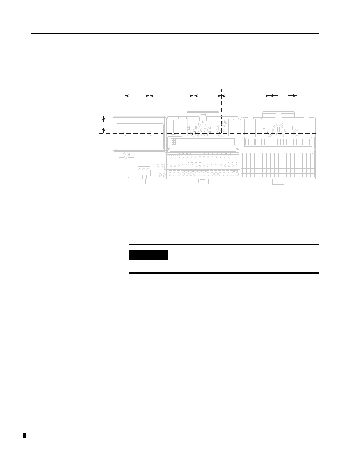
Drilling Dimensions for Panel or Wall Mounting
45327
IMPORTANT
1. Lay out the required points on the wall or panel as shown in the drilling
dimension drawing.
Millimeters
(Inches)
21 (0.83)
35.5
(1.4)
58.5
(2.3)
35.5
(1.4)
58.5
(2.3)
35.5
(1.4)
2. Drill the necessary holes for the #6 self-tapping mounting screws.
3. Mount the mounting plate for the adapter module using two #6
self-tapping screws – 18 screws included for mounting up to 8 modules
and the adapter.
Make certain that the mounting plate is properly grounded to the
panel. Refer to Industrial Automation Wiring and Grounding
Guidelines, publication 1770-4.1
.
Publication 1794-6.5.12 - September 2011
4. Hold the adapter at a slight angle and engage the top of the mounting
plate in the indention on the rear of the adapter module.
5. Press the adapter down flush with the panel until the locking lever locks.
6. Position the terminal base unit up against the adapter and push the
female bus connector into the adapter.
7. Secure to the wall with two #6 self-tapping screws.
8. Repeat for each remaining terminal base unit.
Mount the FLEX I/O Module on the Terminal Base Unit
The Thermocouple, RTD, and mV input module mounts on a 1794-TB3G or
1794-TB3GS terminal base unit.
Page 27

Install Your FLEX I/O Input Module 15
1
2
3
4
5
6
7
8
Label here or under here
40231
ATTENTION
1. Rotate keyswitch (3) on terminal base unit (4) clockwise to position 3 as
required for the module.
Do not change the position of the keyswitch after wiring the terminal
base unit.
Description Description
1 FlexBus connector 5 Base unit
2 Latching mechanism 6 Alignment groove
3 Keyswitch 7 Alignment bar
4 Cap plug 8 Module
2. Make certain the FlexBus connector (1) is pushed all the way to the left
to connect with the neighboring terminal base or adapter.
You cannot install the module unless the connector is fully extended.
3. Make sure the pins on the bottom of the module are straight so they will
align properly with the connector in the terminal base unit.
If you remove or insert the module while the backplane power is on,
an electrical arc can occur. This could cause an explosion in hazardous
location installations. Be sure that power is removed or the area is
nonhazardous before proceeding.
4. Position the module (8) with its alignment bar (7) aligned with the
groove (6) on the terminal base.
5. Press firmly and evenly to seat the module in the terminal base unit.
The module is seated when the latching mechanism is locked into the
module.
Publication 1794-6.5.12 - September 2011
Page 28

16 Install Your FLEX I/O Input Module
IMPORTANT
0123456789101112131415
16 17 18 19 20 21 22 23 24 25 26 27 28 29 30 31 32 33
34 35 36 37 38 39 40 41 42 43 44 45 46 47 48 49 50 51
A
B
C
A
B
C
1794-TB3G or 1794-TB3GK
1794-TB3GS
0...15
34...51
16...33
0 1 2 3 4 5 6 7 8 9 10 11 12 13 14 15
18 19 20 21 22 23 3324 25 26 27 28 29 30 31 3217
35 36 37 38 47 48 49 5034 51
16
39 40 41 42 43 44 45 46
Label placed at top of wiring area
34 and 50 = 24V DC
35 and 51 = common
16 and 33 = chassis
40…45 = chassis ground
35 and 51 = common
34 and 50 = 24V DC
16 and 33 = chassis ground
40…45 = chassis ground
45328
6. Remove cap plug and attach another terminal base unit to the right of
this terminal base unit if required.
Make sure the last terminal base has the cap plug in place.
The adapter is capable of addressing eight modules. Do not exceed a
maximum of eight terminal base units in your system.
Wiring Information
Wiring the module is done using the 1794-TB3G, 1794-TB3GK or the
1794-TB3GS terminal base units.
1794-TB3G, 1794-TB3GK and 1794-TB3GS Wiring
Publication 1794-6.5.12 - September 2011
Connect Wiring to the FLEX I/O Module
Wiring to the TC, RTD, and mV module is made through the terminal base
unit on which the module mounts.
The module is compatible with the 1794-TB3G, 1794-TB3GK and
1794-TB3GS terminal base units.
Connecting Wiring Using a 1794-TB3G, 1794-TB3GK or 1794-TB3GS
Terminal Base Unit
1. Connect individual signal wiring to numbered terminals on 0…15 row
(A), and 17…32 row (B), on the terminal base unit as indicated in the
table below. Use Belden 8761 cable for mV signal wiring, or the
appropriate thermocouple wire for your thermocouples.
Page 29

Install Your FLEX I/O Input Module 17
ATTENTION
Signal wiring shields can be connected to terminals 16 or 33 on row B or
terminals 40…45 on row C.
2. Connect the +V DC power lead to terminal 34 on row C, terminals
34…51.
3. Connect the -V DC common (return-) to terminal 35 on row C,
terminals 34…51.
Do not daisychain power or ground from this terminal base unit to any
AC or DC digital module terminal base units.
4. If daisychaining power to the next terminal base unit, connect a jumper
from terminal 50 (+V DC) on this base unit to +V terminal on the next
terminal base unit.
5. Connect a jumper from terminal 51 (-V DC common) to the -V DC
common terminal on the next terminal base unit.
6. If using cold junction compensators, make these connections as shown
in the CJC Sensor chart below.
Identify RTD Wire Pairs
If the RTD wires are color-coded, the wires that are the same color are
connected together. If the wires are not color-coded, use an ohmmeter to
determine the pairs as explained below.
How to Connect a 4-wire RTD
If the 4-wire RTD wires are all different colors, use an ohmmeter to determine
which leads are connected together. One of the leads in each pair is the
compensation lead. Either lead of the pair can be the compensation lead.
Attach one pair to terminals L and - and the other pair to + and H.
How to Connect a 3-wire RTD
If the 3-wire RTD wires are all different colors, use an ohmmeter to determine
which leads are connected together. Either lead of the pair can be the
compensation lead. Attach one lead of the pair to terminal L and the other to
+. Attach the single lead to -.
Refer to the table, Wiring Connections for the FLEX I/O Input Module, on
page 18.
Publication 1794-6.5.12 - September 2011
Page 30

18 Install Your FLEX I/O Input Module
1
2
1
3
2
1
1a
2
2a
1
2
1
2
2-wire
3-wire
4-wire
Thermocouple
RTD
Millivolt
+
-
mV
45332
45359
Wiring Connections for the FLEX I/O Input Module
Connect the following:
Input types H L + -
Shield
RTD – 2-wire 1 2
RTD – 3-wire 3 1 2
RTD – 4-wire 1a 2a 1 2
Thermocouple 1 2
Millivolt 1 2
(1)
Terminals 37, 38 and 39 and 46, 47 and 48 are for cold junction compensation, with 38 and 47
as chassis GND.
CJC Sensor
Input + Chassis
-
CJC Tail
(1)
Ground
CJC1 C-37 C-38 C-39 A-5 (B-22)
CJC2
(1)
Terminals 37, 38, and 39, and 46, 47, and 48 are for cold junction compensation, with 38
and 47 as chassis GND. Connect the tail of CJC1 to terminal 5 and CJC2 to terminal 12
if channels 0…3 or 0…7 are configured for thermocouples. Connect the tail of CJC1 to
terminal 22 and CJC2 to 29 if channels 4…7 are configured for thermocouples.
C-46
C-
47 C-48 A-12 (B-29)
(1)
Publication 1794-6.5.12 - September 2011
Terminal Base Unit Wiring Connections
1794-TB3G, 1794-TB3GK, and 1794-TB3GS Terminal
(1)
Low
Signal
RTD Source
Current (+)
Signal
Return (-)
RTD or TC
Channel
Base Units
High Signal
Terminal (H)
Terminal (L)
0 A-1 A-2 A-0 A-3
1 A-5 A-6 A-4 A-7
2A-9A-10A-8A-11
3 A-13 A-14 A-12 A-15
4 B-18 B-19 B-17 B-20
5 B-22 B-23 B-21 B-24
6 B-26 B-27 B-25 B-28
7 B-30 B-31 B-29 B-32
+24V DC Power 34 and 50
24V DC Common 35 and 51
(1)
Terminals 37, 38, and 39, and 46, 47 and 48 are for cold junction compensation. Terminals 16, 33
and 40…45 are chassis ground. Connect tail of CJC1 to terminal 5 and CJC2 to 12 if channels
0…3 or 0…7 are thermocouples. Connect tail of CJC1 to terminal 22 and CJC2 to 29 only if
channels 4…7 are used.
Page 31

Install Your FLEX I/O Input Module 19
IMPORTANT
IMPORTANT
17 18 19 20 21 22 23 24 25 26 27 28 29 30 31 32
33
012 34567 891011 12 13 14 15
16
1234567891011121314150
35 36 37 38 39 40 41 42 43 44 45 46
48
49 50 5134
1794-TB3G
0...15
34...51
16...33
A
B
C
4-Wire RTD Channel 3
2-Wire RTD Channel 1
3-Wire RTD Channel 2
+
-
CJC
Thermocouple Channel 4
1
2
2
1
1
3
2
1
1a
2a
2
47
45329
ATTENTION
Disconnecting and reconnecting RTDs or CJCs with power applied
temporarily disturbs the channel steady state data. Allow 2 minutes
for settling time after finishing connections.
If using RTD isolators, use 2- or 4-wire configurations only, and add
digital filtering to the inputs.
Example of 2-, 3- and 4-wire RTD and Thermocouple Wiring to a 1794-TB3G
Terminal Base Unit
Keep exposed area of inner conductor as short as possible.
Publication 1794-6.5.12 - September 2011
Page 32

20 Install Your FLEX I/O Input Module
45330
Example of Millivolt Wiring to a 1794-TB3G Terminal Base Unit
Millivolt
Source
+-
Millivolt
Source
+-
Millivolt
Source
+-
Millivolt
Source
+-
Chapter Summary
1234 567891011121314150
34
2
1
0
17 18 19 20 21 22 23 24 25 26 27 28 29 30 31 32
16
35 36 37 38 39 40 41 42 43 44 45 46 47 48 49 50 5134
5
78
6
910
11
12
13 14
15
0...15
33
16...33
34...51
This chapter provided the user with installation prerequisites and instructions
for the FLEX I/O Input module in an existing programmable controller
system. It also provided the user with instructions on how to wire to a terminal
base unit.
A
B
C
Publication 1794-6.5.12 - September 2011
Page 33

Chapter
ATTENTION
Configure Your FLEX I/O Module with
RSLogix 5000 Software
3
Overview
This chapter describes how to configure the FLEX I/O Thermocouple, RTD,
and mV module for the ControlLogix and CompactLogix system using the
RSLogix 5000 software. The 1794-IRT8 module can communicate through
different networks such as ControlNet, Ethernet, Profibus, among others. In
the examples below, the Ethernet adapter is used for communication between
the Logix processor and the FLEX I/O bus.
If using an SLC controller with ControlNet, refer to the
associated I/O scanner documentation.
If using a PLC 5 controller, refer to the PLC 5 controller
documentation for ControlNet configuration information.
You need to follow these series of steps to fully configure your FLEX I/O
module in the RSLogix 5000 software.
1. Add and configure the new local bridge module, such as 1756-ENBT, to
your project. This user manual assumes you have already properly
configured this module. Refer to the associated documentation.
2. Add and configure the new adapter module, such as a FLEX I/O
EtherNet Adapter (1794-AENT). This user manual assumes you have
already properly configured this module. Refer to the associated
documentation.
3. Add and configure your FLEX I/O module. See the steps provided
below.
4. Download the configuration to the controller.
Add and Configure the FLEX I/O Module
21 Publication 1794-6.5.12 - September 2011
To be able to add your FLEX I/O Thermocouple, RTD, mV module, you
should have already added and configured your Ethernet bridge and/or
adapter.
Page 34

22 Configure Your FLEX I/O Module with RSLogix 5000 Software
Right-click the local adapter module.
Select New Module.
1. In the I/O Configuration tree, right-click the 1794-AENT adapter, and
select New Module.
2. The Select Module dialog appears. Select the FLEX I/O module and
click OK.
Publication 1794-6.5.12 - September 2011
3. Complete the following fields in the New Module dialog that appears.
Click OK.
•Name
• Description
•Comm Format
• Electronic Keying
Page 35

Configure Your FLEX I/O Module with RSLogix 5000 Software 23
4. Click the Connection tab. Specify a value for the Requested Packet
Interval (RPI).
5. Click the Module Info tab to see Module Identification and Status
information. These fields are populated when the module goes online.
6. Click the Input Configuration tab and specify the values for the
following fields:
•Channel
•Sensor
•Sensor Mode
• Input Filter Cutoff
• Data Format
Publication 1794-6.5.12 - September 2011
Page 36

24 Configure Your FLEX I/O Module with RSLogix 5000 Software
Configuration Parameters
Field Name Description Configuration Options
Sensor Allows you to select the main sensor function of your
module, whether Thermocouple or RTD.
You will need to configure your module based on this
main configuration by specifying the next parameters.
Sensor Type Allows you to select one of nine thermocouple types
or one of eight RTD types. Default unit is mV for
thermocouples and ohms for RTDs.
Thermocouple
RTD
For Thermocouple
mV
Type B
Type E
Type J
Type K
Type TXK/XKL(L)
Type N
Type R
Type S
Type T
For RTD
Resistance
100 ohm Pt 385
200 ohm Pt 385
100 ohm Pt 3916
200 ohm Pt 3916
100 ohm Ni 618
200 ohm Ni 618
120 ohm Ni 672
10 ohm Cu 427
To help you select the
proper operating range
of your thermocouple,
see Resolution Curves
for Thermocouples, on
page 65.
To help you specify the
value for your RTD, see
Sensor Types, on page
29.
Publication 1794-6.5.12 - September 2011
Page 37

Configure Your FLEX I/O Module with RSLogix 5000 Software 25
Configuration Parameters
Field Name Description Configuration Options
Sensor Mode Allows you to select the operational mode for the
thermocouple or RTD inputs. For thermocouple inputs,
you can choose the cold junction compensation mode.
For RTD inputs, you can choose 2-wire, 2-wire with
user selected RTD offset, 3-wire, and 4-wire.
Default for thermocouples is external compensation;
default for RTDs is 2-wire (with no offsets).
For Thermocouple
External compensation
Internal compensation
No compensation
Differential compensation
For RTD
2-wire compensation (default)
2-wire with Loop compensation
3-wire
4-wire
For a description of the
different sensor mode
options, for both
Thermocouple and RTD,
see Bit/Word
Descriptions for Block
Transfer Write Words,
on page 34.
When you select
Internal Compensation
for your Thermocouple,
you need to specify a
corresponding
Reference Junction
value. This parameter
sets a fixed reference
junction to compensate
all thermocouple
channels and ranges
from 0 °C…70 °C.
When you select 2-wire
with Loop compensation
for your RTD, you need
to specify values for
each channel for the
RTD Loop
Compensation.
Input Filter Cutoff Allows you to select one of eight levels on input
filtering. The single pole, low pass filtering is
accomplished by the module microprocessor. The filter
selections range from Hardware Only to 5 s time
constant. The times are approximate because they are
based on the module scan time, which varies. The
default is Hardware Only.
Data Format Allows you to specify the format of the data reported.
Module defaults to -4000…10000 in millivolt mode,
and 0…5000 in Ω mode with implied decimal points
(i.e. -40.00mV, 0.1 Ω) whenever °C, °F, °K is selected.
7. After you have completed all the Module Configuration parameters,
click OK in the Module Properties dialog box.
Hardware Filter Only (default)
25 ms
100 ms
250 ms
500 ms
1 s
2 s
5 s
°C
°F
°K
-32767…32767
0…65535
Publication 1794-6.5.12 - September 2011
Page 38

26 Configure Your FLEX I/O Module with RSLogix 5000 Software
You should see the FLEX I/O module in the I/O Configuration tree.
To be able to check if your configured parameters are acceptable and the
configuration is successful, you need to go online.
Refer to the RSLogix 5000 Online Help for detailed descriptions of the
configuration parameters.
Chapter Summary
This chapter provided instructions and required parameters for setting up your
FLEX I/O module on an EtherNet/IP network.
Publication 1794-6.5.12 - September 2011
Page 39

Chapter
4
Read and Write Configuration Maps for the
FLEX I/O Module
Overview
Configure Your Input Module
This chapter describes how to configure, read data from, and map data to your
FLEX I/O Thermocouple, RTD, and mV Input module.
Topic Page
Configure Your Input Module 27
Configurable Options and Their Effect on the Channels 27
Sensor Types 29
Read Data From the Module 30
Map Data for the Module 30
Using Series A Functionality in a Series B Module 38
Chapter Summary 38
The Thermocouple, RTD, and mV input module is configured using a group
of data table words mapped by the processor that is used when the connection
to the module is established.
The software configurable features available are:
• input range selection
• selectable single pole low pass filter
• data reported in °F, °C, °K, mV,
• fault detection
Ω, unipolar or bipolar count
Configurable Options and
There are two types of configurable options: those that affect all channels, and
those that affect each group of 4 input channels.
Their Effect on the
Channels
Options that Affect All Channels
Input Filter Selection
This combination of bits allows you to select one of eight levels on input
filtering. The single pole, low pass filtering is accomplished by the module
27 Publication 1794-6.5.12 - September 2011
Page 40

28 Read and Write Configuration Maps for the FLEX I/O Module
microprocessor. The filter selections range from Hardware Only to 5 s time
constant. The times are approximate because they are based on the module
scan time, which varies. The default is Hardware Only.
Data Format Selection
This set of bits allows you to select one of these five formats:
• Degree C
• Degree F
• Degree K
• Unipolar – The end points for Unipolar are scaled to the end points of
the thermocouple or RTD range. The default unit is mV.
• Bipolar – The end points for Bipolar are scaled to the end points of the
thermocouple or RTD range. It uses
Options that Affect Each Group of Four Inputs
Ω as default unit.
Sensor Type
This set of bits allows you to select one of nine thermocouple types or one of
eight RTD types. Default unit is mV for thermocouples and ohms for RTDs.
Sensor Mode
This set of bits allows you to select the operational mode for the
thermocouple or RTD inputs. For thermocouple inputs, you can choose the
cold junction compensation mode: internal, external, no CJC and differential
measurement between 2 channels, for example, the value of channel 0 minus
the value of channel 1 appears in the channel 0 and channel 1 data table
locations. For RTD inputs, you can choose 2-wire, 2-wire with user selected
RTD offset, 3-wire, and 4-wire. Default for thermocouples is external CJC;
default for RTDs is 2-wire (with no offsets).
Input Types
This set of bits allows you to select one of two input types: thermocouple
(millivolt) or RTD (resistance). The default input type is thermocouple.
Reference Junction
Publication 1794-6.5.12 - September 2011
These bits allow you to select from seven fixed temperatures for the CJC value
that is used by the module in thermocouple mode. Use this mode when the
ambient temperature surrounding the thermocouple connection point is
known and steady. The default temperature is 0 °C (32 °F).
Page 41

Read and Write Configuration Maps for the FLEX I/O Module 29
Fault Mode
You can enable or disable the fault detection. When enabled in thermocouple
mode, each channel is monitored for an open circuit. If an open is detected,
the overrange and fault bits are set for that channel, and the channel data is set
to the maximum value (Series A), or minimum value (Series B) for the chosen
mode of operation.
When enabled in RTD mode, each channel is monitored for an open circuit
(RTD and wires) and short circuits (RTD). If an open is detected, the
overrange and fault bits are set for that channel, and the channel data is set to
the maximum value for the chosen mode of operation. If a short is detected,
the underrange bits is set for that channel, except when in
Ω mode. The
channel data is set to the minimum value for the chosen mode of operation.
RTD Offset
You can select from four fixed resistive values used by the module when inputs
are configured for 2-wire with user selected RTD offset. The RTD offset is
used to nullify the effects of the resistance of long lead wires. Each value
represents the total resistance of both leads of a 2-wire RTD. For example, if
you choose 5
Ω, the module compensates for a total of 5 Ω of lead resistance.
Sensor Types
You can perform a calibration operation that measures the actual total lead
resistance with RTD replaced with a short circuit. The value stored from this
operation is used when the option Use Channel Loop Compensation Value is
selected. This is also the default setting and is initially set to 0 at the factory.
Each channel has its own pair of RTD offset bits and a Channel Loop
Compensation value.
Individual input channels are configurable to operate with the following sensor
types:
RTD Type Thermocouple Type
Sensor type for channels 0…3 Sensor type for channels 0…3
Sensor type for channels 4…7 Sensor type for channels 4…7
Resistance (default) mV (default)
Ω Pt α = 0.00385 Euro (-200…+870 °C) (-328…1598 °F) B 300…1800 °C (572…3272 °F)
100
Ω Pt α = 0.00385 Euro (-200…+400 °C) (-328…752 °F) E -270…1000 °C (-454…1832 °F)
200
Ω Pt α = 0.003916 U.S. (-200…+630 °C) (-328…1166 °F) J -210…1200 °C (-346…2192 °F)
100
Ω Pt α = 0.003916 U.S. (-200…+400 °C) (-328…752 °F) K -270…1372 °C (-454…2502 °F)
200
Ω Nickel α = 0.00618 (-60…+250 °C) (-76…482 °F) TXK/XK(L) -200…800 °C (-328…1472 °F)
100
Ω Nickel α = 0.00618 (-60…+200 °C) (-76…392 °F) N -270…1300 °C (-450…2372 °F)
200
Publication 1794-6.5.12 - September 2011
Page 42

30 Read and Write Configuration Maps for the FLEX I/O Module
ATTENTION
ATTENTION
WARNING
RTD Type Thermocouple Type
120 Ω Nickel α = 0.00672 (-80…+320 °C) (-112…608 °F) R -50…1768 °C (-58…3214 °F)
Ω Copper α = 0.00427 (-200…+260 °C) (-328…500 °F) S -50…1768 °C (-58…3214 °F)
10
You select individual channel ranges using write word 1 of the block transfer
write instruction.
…400 °C (-454…752 °F)
T -270
Disconnecting and reconnecting RTDs with power applied temporarily
disturbs the steady state data of the channel. Allow 2 minutes for
settling time or cycle power to the module after terminating
connections.
If using RTD isolators, we recommend using 2- or 4-wire
configurations only and digital filtering to the inputs.
Read Data From the Module
The range -32768…32767 should only be used with mV selection.
Signals from a thermocouple or RTD are non-linear, the mV selection is
not recommended for thermocouple or RTD real time readings.
If selected, the module will return the mV generated by the
thermocouple or RTD, in addition to any offsets generated by wiring
without any correction for the non-leanearity of the device.
Also, when the module is configured for mV the CJC compensation is
not applied for thermocouple devices.
For thermocouples and RTDs you should use F or C data format. When
configured as thermocouple or RTD the module will use an internal
table to adjust for the non-linear mV returned by the field devices.
After the internal calculations are preformed the module will provide
results in degrees F or C.
Read programming transmits status and data from the TC and RTD input
module to the processor data table in one I/O scan. The processor user
program initiates the request to transfer data from the TC and RTD input
module to the processor.
Map Data for the Module
Publication 1794-6.5.12 - September 2011
The following read and write words and bit/word descriptions describe the
information written to and read from the TC and RTD input module. The
Page 43

Read and Write Configuration Maps for the FLEX I/O Module 31
45333
module uses up to 11 words of input data and up to 4 words of output data.
Each word is composed of 16 bits.
Thermocouple and RTD Input Module Image Table Mapping
Module Image
Input Data Channel 0
I/O Image
Input Size
1...11 Words
Overrange
Channel Faults
Output Size
0...4 Words
Input Data Channel 1
Input Data Channel 2
Input Data Channel 3
Input Data Channel 4
Input Data Channel 5
Input Data Channel 6
Input Data Channel 7
Underrange
SAB
EDT command and data response
RTD Offsets for each channel
EDT command and data
DiagnosticsCJC
Filter CutReference JctData Format FM
Sensor TypeSensor TypeMode ModeTC/RTDTC/RTD
Block Transfer Read and Write
The following block transfer read and write word bit information is presented
for experienced users only.
Input Map (Block Transfer Read)
Dec. 15 14 13 12 11 10 09 08 07 06 05 04 03 02 01 00
Oct. 17 16 15 14 13 12 11 10 07 06 05 04 03 02 01 00
Word 0 Channel 0 Input Data
Word 1 Channel 1 Input Data
Word 2 Channel 2 Input Data
Word 3 Channel 3 Input Data
Word 4 Channel 4 Input Data
Word 5 Channel 5 Input Data
Publication 1794-6.5.12 - September 2011
Page 44

32 Read and Write Configuration Maps for the FLEX I/O Module
Input Map (Block Transfer Read)
Dec. 15 14 13 12 11 10 09 08 07 06 05 04 03 02 01 00
Oct. 17 16 15 14 13 12 11 10 07 06 05 04 03 02 01 00
Word 6 Channel 6 Input Data
Word 7 Channel 7 Input Data
Word 8 Overrange Alarm Bits (channel 0 = bit 8, and so on.) Underrange Alarm Bits (channel 0 = bit 0, and so on.)
Word 9 Ch 7
Word 10 Resp
Where: Ch Flt = Channel Fault
Output Map (Block Transfer Write)
Dec. 15 14 13 12 11 10 09 08 07 06 05 04 03 02 01 00
Oct. 17 16 15 14 13 12 11 10 07 06 05 04 03 02 01 00
Word 0 Reserved Data Format Flt
Word 1 TC/RTD
Ch 4…7
Word 2 RTD Offset
Ch 7
Word 3 Cmd
Flag
Where: Flt = Fault
Ch = Channel
TC/RTD = Thermocouple/Resistance Temperature Detector
EDT = Extended Data Transfer
Ch 6
Ch 5
Ch 4
Ch 3
Ch 2
Ch 1
Ch 0
Res CJC2
Flt
Flt
Flt
Flt
Flt
Flt
Flt
Flt
Command Response Response Data
Flag
CJC = Cold Junction Compensation
SAB = Series of unit; 0 = Series A, 1 = Series B
Alm = Alarm
Sensor
Mode
Ch 4…7
RTD Offset
Ch 6
EDT Command EDT Command Data
Sensor Type
Ch 4…7
RTD Offset
Ch 5
RTD Offset
Ch 4
Alm
Flt
Mode
Ch
4…7
TC/RTD
Ch 0…3
RTD Offset
Ch 3
Mode
Ch
0…3
CJC1
SAB CJC
Alm
Reference Jct. Filter Cutoff
Sensor Mode
Ch 0…3
RTD Offset
Ch 2
Status
Reserved
Sensor Type
Ch 0…3
RTD Offset
Ch 1
RTD Offset
Ch 0
Publication 1794-6.5.12 - September 2011
Bit/Word Descriptions for the Input Module Block Transfer Read Words
Word Dec. Bits
(Octal Bits)
Read Word 0 00…15
(00…17)
Read Word 1 00…15
(00…17)
Read Word 2 00…15
(00…17)
Description
Channel 0 Input data
Channel 1 Input data
Channel 2 Input data
Page 45

Read and Write Configuration Maps for the FLEX I/O Module 33
Read Word 3 00…15
Channel 3 Input data
(00…17)
Read Word 4 00…15
Channel 4 Input data
(00…17)
Read Word 5 00…15
Channel 5 Input data
(00…17)
Read Word 6 00…15
Channel 6 Input data
(00…17)
Read Word 7 00…15
Channel 7 Input data
(00…17)
Read Word 8 00…07 Underrange bits – these bits are set if the input
signal is below the minimum range of the input
channel.
Bit 00 corresponds to channel 0…bit 07 corresponds
to channel 7.
08…15
(10…17)
Overrange bits – these bits are set if 1), the input
signal is above the maximum range of the input
channel; or 2), an input is disconnected.
Bit 08 (10) corresponds to channel 0, bit 09 (11)
corresponds to channel 1, and so on.
Read Word 9 00…03 Diagnostic bits – represent module configuration
and/or hardware errors.
Bit03020100
0 0 0 0 Reserved for factory use
0 0 1 0 Improper module
configuration
0110RAM fault
0 1 1 1 EEPROM fault
0001, 0100, and 0011…1111 Reserved for
factory use
04 Series of Unit (SAB) – 0 = Series A, 1 = Series B
05…06 Cold junction compensation fault bits – These
bits are set (1) when the corresponding cold junction
compensator lead is broken, unattached or shorted,
and the thermocouple is set to "external
compensation.” Bit 05 corresponds to CJC1, and bit
06 to CJC2.
07 Not used
08…15
(10…17)
Fault alarm bits – An alarm bit is set (1) when an
individual input lead opens (broken, disconnected). If
the alarm is enabled, the channel reads maximum
value. Bit 08 (10) corresponds to input channel 0, bit
09 (11) to channel 1, and so on.
Publication 1794-6.5.12 - September 2011
Page 46

34 Read and Write Configuration Maps for the FLEX I/O Module
Word Dec. Bits
Read Word 10 00…07 Extended data table data response bits – These
Bit/Word Descriptions for Block Transfer Write Words
Word Dec. Bits
(Octal Bits)
Description
Write Word 0 00…02 Input Filter Selection bits
Bit 02 01 00 Filter Time Constants – actual filtering depends on the module mode of
0 0 0 Hardware filtering only (default filtering)
0 0 1 25 ms
0 1 0 100 ms
0 1 1 250 ms
1 0 0 500 ms
1011s
1102 s
1115 s
Bits 03…05 Reference Junction – used when input type is set to thermocouple and sensor mode is set to
internal compensation. Sets a fixed reference junction to compensate all thermocouple channels.
Bit 05 04 03 Reference Junction
0 0 0 0 °C (32 °F)
0 0 1 20 °C (68 °F)
0 1 0 25 °C (77 °F)
0 1 1 30 °C (86 °F)
1 0 0 40 °C (104 °F)
1 0 1 50 °C (122 °F)
1 1 0 60 °C (140 °F)
1 1 1 70 °C (158 °F)
Bits 06…07 Fault Mode bits – when a bit is set (1), fault mode is enabled for that channel. Bit 06 corresponds to
channels 0…3; bit 07 corresponds to channels 4…7.
0 = Disabled
1 = Enable wire-off detection
Bits 08…11
(10…13)
Data format – module defaults to -4000…10000 in millivolt mode, and 0…5000 in
implied decimal points (i.e. -40.00mV, 0.1 Ω) whenever °C, °F, °K is selected.
Description
(Octal Bits)
bits echo the EDT command data written to the
module during calibration.
08…14
(10…16)
Extended data table command response bits –
These bits echo the EDT command written to the
module during calibration.
15 (17) Reserved for factory use
operation
Ω mode with
Publication 1794-6.5.12 - September 2011
Page 47

Bit/Word Descriptions for Block Transfer Write Words
Read and Write Configuration Maps for the FLEX I/O Module 35
Word Dec. Bits
Write Word 0
(continued)
(Octal Bits)
Bits 08…11
(10…13)
Description
Bit 11 10 09 08 Data type for channels 0…7
0 0 0 0 °C (implied decimal point xxxx.x)
0 0 0 1 °F (implied decimal point xxxx.x)
0 0 1 0 °K (implied decimal point xxxx.x)
0 0 1 1 -32767…+32767
0 1 0 0 0…65535
0101…1111 not used
Bits 12…15
Not used
(14…17)
Write Word 1 Bits 00…03 Sensor Type (Thermocouple or RTD)
RTD Type
Bit 03 02 01 00 Sensor type for channels 0…3
0 0 0 0 Resistance (default)
0 0 0 1 100 Ω Pt α = 0.00385 Euro (-200…+870 °C) (-328…1598 °F)
0 0 1 0 200 Ω Pt α = 0.00385 Euro (-200…+400 °C) (-328…752 °F)
0 0 1 1 100 Ω Pt α = 0.003916 U.S. (-200…+630 °C) (-328…1166 °F)
0 1 0 0 200 Ω Pt α = 0.003916 U.S. (-200…+400 °C) (-328…752 °F)
0 1 0 1 100 Ω Nickel (-60…+250 °C) (-76…482 °F)
0 1 1 0 200 Ω Nickel (-60…+200 °C) (-76…392 °F)
0 1 1 1 120 Ω Nickel (-80…+320 °C) °F) (-112…608 °F)
1 000 10 Ω Copper (-200…+260 °C) °F) (-328…500 °F)
1001…1111 not used
Thermocouple Type
Bit 03 02 01 00 Sensor type for channels 0…3
0 0 0 0 mV (default)
0 0 0 1 B 300…1800 °C (572…3272 °F)
0 0 1 0 E -270…1000 °C (-454…1832 °F)
0 0 1 1 J -210…1200 °C (-346…2192 °F)
0 1 0 0 K -270…1372 °C (-454…2502 °F)
0 1 0 1 TXK/XK(L) -200…800 °C (-328…1472 °F)
0 1 1 0 N -270…1300 °C (-450…2372 °F)
0 1 1 1 R -50…1768 °C (-58…3214 °F)
1 0 0 0 S -50…1768 °C (-58…3214 °F)
1 0 0 1 T -270…400 °C (-454…752 °F)
1010…1111 not used
Bits 04…05 Sensor Mode Select bits
Bit 05 04 Sensor mode select for channels 0…3
Thermocouple
Publication 1794-6.5.12 - September 2011
Page 48

36 Read and Write Configuration Maps for the FLEX I/O Module
Bit/Word Descriptions for Block Transfer Write Words
Word Dec. Bits
(Octal Bits)
Write Word 1
(continued)
Bits 06…07 Input Type Select
Bits 08…11
(10…13)
Bits 08…11
(10…13)
Description
00External compensation – uses cold junction sensors. Both CJC sensors must be
used when external compensation is selected.
01Internal compensation – uses the user selected Reference Junction Selection.
1 0 No compensation. Data is referenced to 0 °C (32 °F).
1 1 Differential measurement between 2 channels (0…1, 2…3, 4…5, 6…7)
RTD
0 0 2-wire RTD no compensation
0 1 2-wire RTD with user selected RTD offset
1 0 3-wire RTD
1 1 4-wire RTD
Bit 07 06 Input type selection for channels 0…3
0 0 Thermocouple
01RTD
1 0 Not used
1 1 Not used
Sensor Type (Thermocouple or RTD)
RTD Type
Bit 11 10 09 08 Sensor type for channels 4…7
0 0 0 0 Resistance (default)
0 0 0 1 100 Ω Pt α = 0.00385 Euro -200…+870 °C (-328…1598 °F)
0 0 1 0 200 Ω Pt α = 0.00385 Euro -200…+400 °C (-328…752 °F)
0 0 1 1 100 Ω Pt α = 0.003916 U.S. -200…+630 °C (-328…1166 °F)
0 1 0 0 200 Ω Pt α = 0.003916 U.S. -200…+400 °C (-328…752 °F)
0 1 0 1 100 Ω Nickel -60…+250 °C (-76…482 °F)
0 1 1 0 200 Ω Nickel -60…+200 °C (-76…362 °F)
0 1 1 1 120 Ω Nickel -80…+320 °C (-112…608 °F)
1 0 0 0 10 Ω Copper -200…+260 °C (-328…470 °F)
1001…1111 not used
Thermocouple Type
Bit 11 10 09 08 Sensor type for channels 4…7
0 0 0 0 mV (default)
0 0 0 1 B 300…1800 °C (572…3272 °F)
0 0 1 0 E -270…1000 °C (-454…1832 °F)
0 0 1 1 J -210…1200 °C (-346…2192 °F)
0 1 0 0 K -270…1372 °C (-454…2502 °F)
0 1 0 1 TXK/XK(L) -200…800 °C (-328…1472 °F)
0 1 1 0 N -270…1300 °C (-450…2372 °F)
0 1 1 1 R -50…1768 °C (-58…3214 °F)
1 0 0 0 S -50…1768 °C (-58…3214 °F)
Publication 1794-6.5.12 - September 2011
Page 49

Bit/Word Descriptions for Block Transfer Write Words
Read and Write Configuration Maps for the FLEX I/O Module 37
Word Dec. Bits
(Octal Bits)
Bits 12…13
(14…15)
Bits 14…15
(16…17)
Write Word 2 00…15
(00…17)
Description
1 0 0 1 T -270…400 °C (-454…752 °F)
1010…1111 not used
Sensor Mode Select bits
Bit 13 12 Sensor mode select for channels 4…7
Thermocouple
00External compensation – uses cold junction sensors. Both CJC sensors must be
used when external compensation is selected.
01Internal compensation – uses the user selected Reference Junction.
1 0 No compensation. Data is referenced to 0 °C (32 °F).
1 1 Differential measurement between 2 channels.
RTD
0 0 2-wire RTD no compensation
0 1 2-wire RTD with user selected offset
1 0 3-wire RTD
1 1 4-wire RTD
Input Type Select
Bit 15 14 Input type selection for channels 4…7
0 0 Thermocouple
0 1 RTD
1 0 Not used
1 1 Not used
RTD offset select bits – used when input type is set to RTD and sensor mode select is set to 2-wire
with user selected RTD offset. Allows you to set the type of RTD loop resistance compensation used
for all RTDs or one of three fixed values for all channels.
NOTE: Not applicable to 10 Ω copper RTD.
Bit 01 00 RTD Offset Select Bits – channel 0
03 02 RTD Offset Select Bits – channel 1
05 04 RTD Offset Select Bits – channel 2
07 06 RTD Offset Select Bits – channel 3
09 08 RTD Offset Select Bits – channel 4
11 10 RTD Offset Select Bits – channel 5
13 12 RTD Offset Select Bits – channel 6
15 14 RTD Offset Select Bits – channel 7
0 0 Use channel loop compensation value stored during calibration procedure for 2-wire
RTD (default = 0 Ω)
015 Ω (total lead resistance)
1010 Ω (total lead resistance)
1 1 15 Ω
Publication 1794-6.5.12 - September 2011
Page 50

38 Read and Write Configuration Maps for the FLEX I/O Module
ATTENTION
Bit/Word Descriptions for Block Transfer Write Words
Word Dec. Bits
(Octal Bits)
Write Word 3 00…07 Extended data table data bits – These bits are written to the module during calibration. They are
08…14
(10…16)
15 (17) Reserved for factory use only
Using Series A Functionality in a Series B Module
Description
used to define offset, gain and general channel calibration.
Extended data table command bits – These bits are written to the module during calibration. They
are used to select channel calibration action.
To employ Series A functionality when using a Series B 1794-IRT8 module,
connect a wire from terminal 39 to terminal 48 on the 1794-TB3G or
1794-TB3GS terminal base unit. When terminals 39 and 48 are wired together,
bit 4 in read word 9 will not be set (0), indicating the module is in Series A
functionality.
If these terminals are not connected together, the Series B
product will default to Series B functionality.
Chapter Summary
This chapter provided the user with data and instructions to configure and
map data for the FLEX I/O Thermocouple, RTD, and Millivolt Input
module.
Publication 1794-6.5.12 - September 2011
Page 51

Calibrate Your Module
ATTENTION
IMPORTANT
Chapter
5
Overview
This chapter provides the tools and equipment, and procedure for calibrating
your FLEX I/OThermocouple, RTD, and mV input module.
Topic Page
When and How to Calibrate Your FLEX I/O Module 39
Tools and Equipment 40
Calibrate Your Input Module 40
Calibration Setup 41
Wiring Connections for Calibrating the Thermocouple and RTD
Input Module
Read and Write Words for Calibration 42
EDT Calibration Command and Command Data Summary 44
Offset Calibration 45
Gain Calibration 46
Current Source Calibration 47
Cold Junction Calibration 49
Channel Loop Compensation Calibration 49
Chapter Summary 49
41
When and How to Calibrate Your FLEX I/O Module
39 Publication 1794-6.5.12 - September 2011
This module is shipped to you already calibrated. If a calibration check is
required, the module must be in a FLEX system. We recommend recalibrating
your module, if the module is going to be used in an environment with
temperature other than 25 °C (77 °F) and 30% humidity.
Perform module calibration periodically, based on your application, or
at least once a year. Module calibration may also be required to
remove module error caused by aging components in your system.
Offset calibration must be done first, followed by gain calibration.
You must use a 1794-TB3G or 1794-TB3GS terminal base when
calibrating this module.
Calibration can be accomplished using the manual calibration procedure
described in the following sections.
Page 52

40 Calibrate Your Module
ATTENTION
IMPORTANT
Tools and Equipment
Calibrate Your Input Module
To calibrate your Thermocouple, RTD, and mV input module, you will need
the following tools and equipment:
Tool or Equipment Description
Precision Resistors High Precision Resistors:
383 W, 0.01%, 5ppm/°C
100 W, 0.01%, 5ppm/°C
10 KΩ, 0.5%, 5ppm/°C
Precision Voltage Source 320 mV, 1 μV resolution Analogic 3100, Data Precision
8200 or equivalent
Industrial Terminal and
Interconnect Cable
Programming terminal for Allen-Bradley family processors
You must calibrate the module in a FLEX I/O system. The module must
communicate with the processor and an industrial terminal. You can
calibrate input channels in any order, or all at once.
To allow the internal module temperature to stabilize, apply power to
the module at least 20 minutes before calibration.
When using remote I/O, before calibrating your module, you must enter
ladder logic into the processor memory, so that you can initiate block transfer
writes (BTW) to the module, and read inputs (BTR) from the module.
To manually calibrate the module:
1. Apply a reference to the desired input(s).
2. Send a message to the module indicating which inputs to read and what
calibration step is being performed (offset).
The module returns a response which echoes the message sent to the
module. The module stores this input data.
3. Apply a second reference signal to the module.
4. Send a second message indicating which inputs to read and what
calibration step is being performed (gain).
The module computes new calibration values for the inputs and returns
a response which echoes back the message sent to the module. If the
calibration cannot be completed, the module returns a fault message.
Publication 1794-6.5.12 - September 2011
Page 53

Calibration Setup
1
2
3
4 5 6 7 8 9 10 11 12 13 14 150
Using Precision Resistors for 383 Ω and 100 Ω calibration
17 18 19 20 21 22 23 24 25 26 27 28 29 30 31 32
33
16
0 1 2 3 4 5 6 7 8 9 10 11 12 13 14 15
35 36 37 38 39 40 41 42 43 44 45 46 47 48 49 50 5134
17 18 19 20 21 22 23 24 25 26 27 28 29 30 31 32 3316
0 1 2 3 4 5 6 7 8 9 10 11 12 13 14 15
1234567891011121314150
35 36 37 38 39 40 41 42 43 44 45 46 47 48 49 50 5134
1794-TB3G
Precision Voltage Source
Using Precision Voltage Source for offset and gain calibration
+-
Connect + to terminals 2, 6, 10, 14, 19, 23, 27, and 31
Connect - to terminals 3, 7, 11, 15, 20, 24, 28 and 32
Connect one 10 K Ω, 0.5% resistor across terminals 37 and 39 and another across 46 and 48.
45357
+
-
mV
1
1a
2
2a
1
2
4-wire
RTD
Millivolt
45358
Calibrate Your Module 41
Wiring Connections for Calibrating the Thermocouple and RTD Input Module
Type of Input Connect the following
HL+-Shield
RTD – 4-wire 1a 2a 1 2
Millivolt 1 2
Wiring to the 1794-TB3G and 1794-TB3GS Terminal Base Units
RTD or
1794-TB3G and 1794-TB3GS Terminal Base Units
Thermocouple
Channel
High Signal
Terminal (H)
Low Signal
Terminal (L)
RTD Source
Current (+)
01203
15647
2910811
313141215
418191720
522232124
626272528
Publication 1794-6.5.12 - September 2011
(1)
Signal Return
(-)
Page 54

42 Calibrate Your Module
Wiring to the 1794-TB3G and 1794-TB3GS Terminal Base Units
RTD or
1794-TB3G and 1794-TB3GS Terminal Base Units
(1)
Thermocouple
Channel
High Signal
Terminal (H)
Low Signal
Terminal (L)
RTD Source
Current (+)
Signal Return
(-)
730 312932
24V DC Power 34 and 50
24V DC
35 and 51
Common
(1)
Terminals 16, 33 and 40…45 are chassis ground.
Read and Write Words for Calibration
The following tables provide read and write words for module calibration.
Write Words for Calibration
Decimal 151413121110090807 06 05 04 03 02 01 00
Octal 171615141312111007 06 05 04 03 02 01 00
⇓ Write
Word
0 Reserved Data Format Flt
Mode
Ch
0…3
1TC/RTD
Ch. 4…7
Sensor
Mode
Sensor Type Ch 4…7 TC/RTD Ch.
0…3
Flt
Mode
Ch
4…7
Ch 4…7
2 RTD Offset
Ch 7
RTD Offset
Ch 6
RTD Offset
Ch 5
RTD Offset
Ch 4
RTD Offset
Ch 3
3 EDT command EDT command data
Reference Junction Filter Select
Sensor Mode
Sensor Type Ch 0…3
Ch 0…3
RTD Offset
Ch 2
RTD Offset
Ch 1
RTD Offset
Ch 0
Where: Flt = Fault
TC/RTD = Thermocouple/Resistance Temperature Detector
EDT = Extended Data Transfer
Read Words for Calibration
Decimal15141312111009080706050403020100
Octal 17161514131211100706050403020100
Word⇓ Read
0 Channel 0 Input Data
1 Channel 1 Input Data
2 Channel 2 Input Data
3 Channel 3 Input Data
4 Channel 4 Input Data
Publication 1794-6.5.12 - September 2011
Page 55

Calibrate Your Module 43
ATTENTION
Read Words for Calibration
Decimal15141312111009080706050403020100
Octal 17161514131211100706050403020100
Word⇓ Read
5 Channel 5 Input Data
6 Channel 6 Input Data
7 Channel 7 Input Data
8 Overrange Alarm Bits (channel 0 = bit 08, and so on.) Underrange Alarm Bits (channel 0 = bit 00, and so on.)
9 Ch7
10 EDT command response EDT data response
Where: Flt = Fault
Ch6
Ch5
Ch4
Ch3
Ch2
Ch1
Flt
Flt
Flt
Flt
Flt
Flt
Flt
CJC = Cold Junction Compensation
SAB = Series of unit; 0 = Series A; 1 = Series B
Ch0
Flt
CJC 2
Flt
CJC 1
Flt
SAB Diagnostic Status
The CJC Status bit, Read Word 9, Bit 3 is added with the Firmware C
release of the 1794-IRT8 Series B module.
The CJC Status bit is turned On when the temperature between the
CJCs is greater than 6 °C but less than 12 °C.
When this temperature difference is above 12 °C, then the CJC Alarm
bits are set.
Also, if a CJC temperrature is over-range or under-range, then the
associated CJC Alarm bit is set. In this condition, the CJC Status bit is
not set.
The CJC Status bit does not exist in Series A.
Publication 1794-6.5.12 - September 2011
Page 56

44 Calibrate Your Module
EDT Calibration Command and Command Data Summary
Config Word 3
EDT Command
Meaning Config Word 3
bits 4…7
Config Word 3
bits 0…3
bits 8…15
Dec. (Hex) Channel No. Command data
4 (4) General calibration
0…7 1 Channel internal current source
by channel
0…7 2 Channel internal current source
0…7 3 Loop channel compensation for
0…7 4 CJC calibration
5 (5) Offset calibration
0…7 0 gain= 1, input = -320 mV
by channel
0…7 1 gain = 2, input = 0.0 mV
0…7 2 gain = 4, input = -50 mV
0…7 3 gain = 8, input = -10.0 mV
0…7 4 gain = 16, input = -9 mV
0…7 5 gain = 32, input = 1.0 mV
6 (6) Gain calibration by
0 gain = 1, input = 320 mV
channel
1 gain = 2, input = 320 mV
2 gain = 4, input = 110 mV
Meaning
and current sense resistor, with
4-wire external 383 Ω inputs
and current sense resistor with
4-wire external 100 Ω inputs
2-wire RTD
36 (24) Calibration all
Publication 1794-6.5.12 - September 2011
channels
General calibration
all channels
Offset calibration
all channels
3 gain = 8, input = 70 mV
4 gain = 16, input = 29 mV
5 gain = 32, input = 19 mV
0 1 Channel internal current source
and current sense resistor, with
4-wire external 383 Ω inputs
0 2 Channel internal current source
and current sense resistor with
4-wire external 100 Ω inputs
0 3 Loop channel compensation for
2-wire RTD
0 4 CJC calibration
1 0 gain = 1, input = -320 mV
Page 57

Calibrate Your Module 45
Config Word 3
EDT Command
bits 8…15
Meaning Config Word 3
bits 4…7
1 1 gain = 2, input = 0.0 mV
1 2 gain = 4, input = -50 mV
1 3 gain = 8, input = -10.0 mV
1 4 gain = 16, input = -9 mV
1 5 gain = 32, input = 1.0 mV
Gain calibration all
channels
2 0 gain = 1, input = 320 mV
2 gain = 2, input = 320 mV
2 gain = 4, input = 110 mV
2 gain = 8, input = 70 mV
2 gain = 16, input = 29 mV
2 gain = 32, input = 19 mV
Offset Calibration
Config Word 3
bits 0…3
Meaning
Inputs can be calibrated one at a time or all at once. To calibrate the offsets,
proceed as follows:
1. Apply power to the module for 20 minutes before calibrating.
2. Connect a precision millivolt source across each input channel. Set the
source to -320.00 mV for a gain of 1. Connect all (L) signal terminals
together and attach to the positive lead from the precision voltage
source. Connect all (-) signal terminals together and attach to the
negative lead.
EDT Commands for Offset Calibration
All Channels Single Channel
EDT
EDT Command
Gain
Selected
1 -320.00 + 0.064 mV 2410 9232 05
2 0.000 + 0.032 mV 2411 9233 05
4 -50.00 + 0.016 mV 2412 9234 05
Input (mV) Hex Decimal Bits
Command
Dec. or Hex
Bits 8
…15
EDT Command
Data
Dec. or Hex
Bits
4
0
0
0
…7
…7
…7
…7
0…3
0
1
2
Publication 1794-6.5.12 - September 2011
Page 58

46 Calibrate Your Module
EDT Commands for Offset Calibration
All Channels Single Channel
EDT Command
Gain
Selected
Input (mV) Hex Decimal Bits
EDT
Command
Dec. or Hex
Bits 8
…15
EDT Command
Data
Dec. or Hex
Bits
4
…7
0…3
8 -10.00 + 0.008 mV 2413 9235 05
16 -9.00 + 0.004 mV 2414 9236 05
32 1.000 + 0.002 mV 2415 9237 05
0
0
0
…7
…7
…7
3. Initiate a write to the module with the appropriate value in the EDT
command location (write word 3, bits 00…15), as shown above.
4. Monitor the EDT response location (read word 11 bits 00…15) for an
echo of the EDT command. Depending on which command you sent, it
should show 241X Hex.
If the EDT response word reads 80FF (hex), repeat the step 3. Make
sure that sufficient time is allowed for the module to respond to your
request. If there is no change, calibration has failed. Check the wiring
and try again.
5. Set the precision millivolt source to the value required for a gain of 2.
Repeat steps 3 and 4 for gain 2. Repeat for each gain setting.
6. When all offset calibrations are successful, proceed to the gain
calibration.
3
4
5
Publication 1794-6.5.12 - September 2011
Gain Calibration
After completing the offset calibration, proceed with the gain calibration.
1. Connect a precision millivolt source across each input channel. Set the
source to 320.00 mV for a gain of 1. Connect all (L) signal terminals
together and attach to the positive lead from the precision voltage
source. Connect all (-) signal terminals together and attach to the
negative lead.
Page 59

EDT Commands for Gain Calibration
All Channels Single Channel
EDT Command EDT
Gain
Selected
Input (mV) Hex Decimal Bits
Calibrate Your Module 47
EDT Command
Data
Command
Dec. or Hex
Bits 8
…15
Dec. or Hex
4
…7
Bits
0…3
1 -320.00 + 0.064 mV 2420 9248 06
2 320.00 + 0.032 mV 2421 9249 06
4 110 + 0.016 mV 2422 9250 06
8 70.00 + 0.008 mV 2423 9251 06
16 29.00 + 0.004 mV 2424 9252 06
32 19.00 + 0.002 mV 2425 9253 06
0
0
0
0
0
0
…7
…7
…7
…7
…7
…7
0
1
2
3
4
5
2. Apply power to the module for 20 minutes before calibrating.
3. After the connections stabilize, initiate a write word with the appropriate
EDT command location (write word 3, bits 00…15) as shown above.
4. Monitor the value in the EDT response location (read word 11,
bits 00…15) for an echo of the EDT command. Depending on which
command you sent, it should show 242X Hex.
If the EDT response word reads 80FF (hex), repeat step 3. Make sure to
allow for sufficient time for the module to respond to your request. If
there is no change, calibration has failed. Check the wiring and try again.
5. Set the precision millivolt source to the value required for a gain of 2.
Repeat steps 3 and 4 for gain 2. Repeat for each gain setting.
When all gain calibrations are successful, proceed to perform Current Source
Calibration on page 47.
Current Source Calibration
The current sources can be calibrated one at a time or all at once. To calibrate
all the current sources, proceed as follows:
1. Connect a 383
channel (8 resistors).
2. Apply power to the module for 20 minutes before calibrating.
Ω, 0.01% resistor across (H, +) and (L, -) of each input
Publication 1794-6.5.12 - September 2011
Page 60

48 Calibrate Your Module
3. Initiate a write to the module with 2401 (hex) value in EDT command
location (word 3, bits 00…15), as shown, for calibrating all channels at
once. For individual channel calibrations, use the 04X1 (hex) (0401,
0411, 0421, ...0471 hex).
4. Monitor the EDT response location (read word 10, bits 00…15) for an
echo of the EDT command.
If the EDT response word reads 80FF (hex), repeat step 3. Make sure to
allow for sufficient time for the module to respond to your request. If
there is no change, calibration has failed. Check the wiring and try again.
5. Connect a 100
Ω, 0.01% resistor across (H, +) and (L, -) of each input
channel (8 resistors). Repeat steps 3 and 4 using the EDT command
value of 2402 (hex) for calibrating all channels at once. For individual
channel calibrations, use the 04X2 (hex) (0402, 0412, 0422, ...0472 hex).
When all calibrations are successful, proceed to the Cold Junction Calibration
on page 47.
Publication 1794-6.5.12 - September 2011
Page 61

Calibrate Your Module 49
Cold Junction Calibration
Both cold junction compensation inputs must be calibrated at at the same
time. To calibrate both at once, proceed as follows:
1. Connect 10 K
terminals 46 and 48 (CJC 2).
2. Apply power to the module for 20 minutes before calibrating.
3. Initiate a write to the module with 2404 (hex) value in the EDT
command location (word 3, bits 00…15).
4. Monitor the EDT response location (read word 11, bits 00…15) for an
echo of the EDT command.
If the EDT response word reads 80FF (hex), repeat step 3. Make sure that
sufficient time is allowed for the module to respond to your request. If there is
no change, calibration has failed. Check the wiring and try again.
Ω, 0.5% resistors across terminals 37 and 39 (CJC 1) and
Channel Loop Compensation Calibration
Each 2-wire RTD can be calibrated individually, or at the same time. Proceed
as follows.
1. Short circuit the end of each input cable at the RTD element. Do this
for all the channels to be calibrated.
Chapter Summary
2. Apply power to the module for 20 minutes before calibrating.
3. Initiate a write to the module with 2403(hex) (calibrate all channels) in
the EDT command location (write word 3, bits 00…15). For individual
channel calibrations, use 04X3 (hex) (0403, 0413, 0423, ...0473).
4. Monitor the EDT response location (read word 1X, bits 00…15) for an
echo of the EDT command.
If the EDT response word reads 80FF (hex), repeat step 3. Make sure that
sufficient time is allowed for the module to respond to your request. If there is
no change, calibration has failed. Check the wiring and try again.
This chapter provided the user with instructions on how to calibrate your
FLEX I/O Thermocouple, RTD, and mV input module.
Publication 1794-6.5.12 - September 2011
Page 62

50 Calibrate Your Module
Notes:
Publication 1794-6.5.12 - September 2011
Page 63

Troubleshoot the Module
A – Insertable label for writing individual input designations
B – Fault Indicator - indicates noncritical fault
C – Power Indicator - indicates power applied to module A
AB C
Chapter
6
Overview
Module Indicators
This chapter provides a description of the different status indicators for the
FLEX I/O Thermocouple, RTD, and mV module to help you troubleshoot.
The FLEX I/O module has one status indicator (PWR) that is On when
power is applied to the module, and one fault indicator (F) for each input.
TC RTD INPUT 8 CHANNEL
IN 0 IN 2 IN 4 IN 6IN 1 IN 3 IN 5 IN 7
FFFFFFFF
1794-IRT8
3
PWR
Status Indicators
Indicator Color State Description
Fault Red On At power up – Channel 0 indicator lights at power up until all internal
diagnostics are checked. After successful power up, the indicator
goes off if no fault is detected and the module has started
communicating with an adapter.
After successful power up – Indicates a critical fault, such as
diagnostic failure. If channel indicator stays solid red after power up,
there is an internal module error. Try cycling power. If problem
persists, replace module.
If channel indicator continues to blink after power up, communication
between the module and the adapter has not been established.
51 Publication 1794-6.5.12 - September 2011
Page 64

52 Troubleshoot the Module
Status Indicators
Indicator Color State Description
Power Off Module not powered
Blinking
(when faults
are enabled,
and bit set)
Green On Module receiving power
Indicates a noncritical fault (such as open sensor). Input data set to
maximum, and indicator flashes at about 1 Hz rate.
The FLEX I/O Thermocouple, RTD, and mV module returns diagnostics to
the processor in Word 9 of the block transfer read (BTR) file. These
diagnostics give you information on the status or condition of the module.
Diagnostic Bits in Word 9
Word Dec. Bits
(Octal Bits)
Read Word 9 00…03 Diagnostic bits – represent module configuration
04 Series of Unit (SAB) – 0 = Series A, 1 = Series B
05…06 Cold junction compensation fault bits – These
07 Not used
08…15
(10…17)
Description
and/or hardware errors.
Bit03020100
0 0 0 0 Reserved for factory use
0 0 1 0 Improper module
configuration
0110RAM fault
0 1 1 1 EEPROM fault
0001, 0100, and 0011…1111 Reserved for
factory use
bits are set (1) when the corresponding cold junction
compensator lead is broken, unattached or shorted,
and the thermocouple is set to "external
compensation.” Bit 05 corresponds to CJC1, and bit
06 to CJC2.
Fault alarm bits – An alarm bit is set (1) when an
individual input lead opens (broken, disconnected). If
the alarm is enabled, the channel reads maximum
value. Bit 08 (10) corresponds to input channel 0, bit
09 (11) to channel 1, and so on.
Chapter Summary
Publication 1794-6.5.12 - September 2011
This chapter specified the different status indicators that would help the user
troubleshoot the module.
Page 65

Specifications
Appendix
A
Overview
This appendix contains general and environmental specifications and
certifications for the FLEX I/O Thermocouple, RTD, mV Input Modules.
General Specifications
Attribute Value
Number of inputs 8 channels (2 groups of 4)
Module location Cat. Nos. 1794-TB3G, 1794-TB3GS, 1794-TB3GK Terminal
base units
Nominal input voltage
ranges
Supported
thermocouple types
Supported RTD types Resistance
-40…100 mV DC for thermocouples
0…325 mV for RTDs
mV default
Ty pe
B
E
J
K
TXK/XK(L)
N
R
S
T
100 Ω Pt α = 0.00385 Euro -200…870 °C (-328…1598 °F)
200 Ω Pt α = 0.00385 Euro -200…400 °C (-328…752 °F)
100 Ω Pt α = 0.003916 U.S. -200…630 °C (-328…1166 °F)
100 Ω Pt α = 0.003916 U.S. -200…400 °C (-328…752 °F)
Range °C
300…1800 °C
-270…1000 °C
-210…1200 °C
-270…1372 °C
200…800 °C
-270…1300 °C
-50…1768 °C
-50…1768 °C
-270…400 °C
Range °F
(572…3272 °F)
(-454…1832 °F)
(-346…2192 °F)
(-454…2502 °F)
(-328…1472 °F)
(-454…2372 °F)
(-58…3214 °F)
(-58…3214 °F)
(-454…752 °F)
100 Ω Nickel -60…250 °C (-76…482 °F)
200 Ω Nickel -60…200 °C (-76…362) °F)
120 Ω Nickel -80…320 °C (-112…608 °F)
10 Ω Copper -200…260 °C (-328…470 °F)
Resolution 14 bits
Accuracy vs. filter cutoff 0.05% of full range in millivolt mode with filtering selected
Hardware only = 0.10% of full range in millivolt mode
Data format °C (implied decimal point XXX.X)
°F (implied decimal point XXX.X)
°K (implied decimal point XXX.X)
-32767…32767
0…65535
0…5000 ohms mode (implied decimal point XXX.X)
-4000…+10000 millivolt mode (implied decimal
point XXX.XX)
Common mode rejection -80 db @ 5V peak-to-peak, 50…60 Hz
Common mode input range +
53 Publication 1794-6.5.12 - September 2011
15V min
Page 66

54 Specifications
General Specifications
Attribute Value
Isolation voltage
(continuous voltage
withstand rating)
System throughput (8
channels scanned) – Add
0.5 ms if filtering is
selected
Open circuit protection
50V (continuous), Basic Insulation Type
Type tested @ 1365V AC for 60 s, between field side
and system
No isolation between individual channels
Typical module timing is shown here.
7.4 ms - millivolt
8.0 ms - Ω - 2-wire RTD
10.0 ms - Ω - 3-wire RTD
10.4 ms - Ω - 4-wire RTD
8.0 ms - 2-wire RTD (°F)
10.4 ms - 4-wire RTD (°F)
8.8 ms - 2-wire RTD (°C), (°K)
10.8 ms - 4-wire RTD (°C), (°K)
9.8 ms - 3-wire RTD (°F)
10.0 ms - 3-wire RTD (°C), (°K)
9.0 ms - Thermocouples (°F)
9.4 ms - Thermocouples (°C), (°K)
RTD mode – Open input – Module defaults to max value
TC mode – Open input – Module defaults to min value
To simulate wire-off detection in Series A TC mode when using
a Series B module, attach a jumper from terminal 39 to terminal
48 on the 1794-TB3G, 1794-TB3GS, or 1794-TB3GK terminal
base unit so that an open input will default to max value.
Open input detection time Immediate detection 2 scans, max
Overvoltage capability 15V DC continuous at 25 °C
Overall drift with
temperature, max
Cold junction
compensation range
Cold junction compensator Allen-Bradley catalog number 1794-CJC2
Indicators 1 green power status indicator
FlexBus current 40 mA
Power dissipation, max 3.0 W @ 31.2V DC
Thermal dissipation, max 10.2 BTU/hr @ 31.2V DC
Keyswitch position 3
External DC power
supply voltage
Voltage range
Supply current
Dimensions (with module
installed in base) HxWxD
approx.
Temperature code, IEC T4
50 ppm/°C of span
-20…100 °C
8 red open input indicators
24V DC nom
95 mA @ 24V DC
94 x 94 x 69 mm
(3.7 x 3.7 x 2.7 in.)
Publication 1794-6.5.12 - September 2011
Page 67

General Specifications
Attribute Value
Temperature code, North
American
Enclosure type rating None (open-style)
Wire size Determined by installed terminal base
Signal conductors
T4A
Specifications 55
Thermocouple
Millivolt
Wire type
Wiring category
Use appropriate shielded thermocouple wire
Belden 8761
Shielded on signal ports
(1)
2 – on signal ports
(2)
3 – on power ports
Terminal screw torque for
Determined by installed terminal base
cage-clamp terminal base
(1)
Refer to the thermocouple manufacturer for proper thermocouple extension.
(2)
Use this category information for planning conductor routing as described in Industrial Automation Wiring and
Grounding Guidelines, Allen-Bradley publication 1770-4.1
.
Environmental Specifications
Attribute Value
Temperature, operating IEC 60068-2-1 (Test Ad, Operating Cold),
IEC 60068-2-2 (Test Bd, Operating Dry Heat),
IEC 60068-2-14 (Test Nb, Operating Thermal Shock):
-20…55 °C (-4…131 °F) (1794-IRT8, 1794-IRT8K)
-20…70 °C (-4…158 °F) (1794-IRT8XT)
Temperature,
non- operating
IEC 60068-2-1 (Test Ab, Unpackaged Non-operating Cold),
IEC 60068-2-2 (Test Bb, Unpackaged Non-operating Dry Heat),
IEC 60068-2-14 (Test Na, Unpackaged Non-operating
Thermal Shock):
-40…85 °C (-40…185 °F)
Relative humidity IEC 60068-2-30 (Test Db, Unpackaged Damp Heat):
5…95% noncondensing
Vibration IEC 60068-2-6 (Test Fc, Operating):
5 g @ 10…500 Hz
Shock
operating
nonoperating
IEC60068-2-27 (Test Ea, Unpackaged shock):
30 g
50 g
Emissions CISPR 11:
Group 1, Class A (with appropriate enclosure)
ESD immunity IEC 61000-4-2:
6 kV contact discharges
8 kV air discharges
Publication 1794-6.5.12 - September 2011
Page 68

56 Specifications
ATTENTION
Environmental Specifications
Attribute Value
Radiated RF immunity IEC 61000-4-3:
10V/m with 1 kHz sine-wave 80% AM from 80…2000 MHz
10V/m with 200 Hz 50% Pulse 100% AM at 900 MHz
10V/m with 200 Hz 50% Pulse 100% AM at 1890 MHz
3V/m with 1 kHz sine-wave 80% AM from 2000…2700 MHz
EFT/B immunity IEC 61000-4-4:
±2 kV at 5 kHz on power ports
±2 kV at 5 kHz on shielded signal ports
Surge transient
immunity
IEC 61000-4-5:
±2 kV line-earth(CM) on shielded signal ports
Conducted RF immunity IEC 61000-4-6:
10V rms with 1 kHz sine-wave 80% AM from
150 kHz…80 MHz on shielded signal ports
To comply with the CE Low Voltage Directive (LVD), all connections to
this equipment must be powered from a source compliant with
the following:
Safety Extra Low Voltage (SELV) or Protected Extra Low Voltage (PELV).
Certifications
Certification (when
product is marked)
c-UL-us UL Listed Industrial Control Equipment, certified for US and
CE
C-Tick Australian Radiocommunications Act, compliant with:
Value
(1)
Canada. See UL File E65584.
UL Listed for Class I, Division 2 Group A,B,C,D Hazardous
Locations, certified for U.S. and Canada. See UL File E194810.
European Union 2004/108/EC EMC Directive, compliant with:
EN 61326-1; Meas./Control/Lab., Industrial Requirements
EN 61000-6-2; Industrial Immunity
EN 61000-6-4; Industrial Emissions
EN 61131-2; Programmable Controllers (Clause 8, Zone A & B)
AS/NZS CISPR 11; Industrial Emissions
Publication 1794-6.5.12 - September 2011
Ex European Union 94/9/EC ATEX Directive, compliant with:
EN 60079-15; Potentially Explosive Atmospheres, Protection
"n" (II 3 G Ex nA IIC T4 X)
EN 60079-0; General Requirements (Zone 2)
TÜV TÜV Certified for Functional Safety:
up to and including SIL 2
(1)
See the Product Certification link at http://www.ab.com for Declarations of Conformity, Certificates, and other
certification details.
Page 69

Appendix
Electronic Data Sheet (EDS) Files
B
Overview
EDS provides the definition for a device’s configurable parameters and public
interfaces to those parameters.
Every type of configurable device has its own unique EDS. It is a simple text
file that allows product-specific information to be made available to
third-party vendors.
This makes updating of configuration tools easier without having to constantly
revise the configuration software tool.
Beginning with the following revisions, EDS files are required for RSNetworx
for Devicenet and ControlNet, RSLinx, RSLogix5, and RSLogix 5000 software
to recognize a device:
RSNetworx Version 2.21
RSLinx Version 1.10.176
RSLogix5 Version 4.0
RSLogix5000 Version 5.12
Updating EDS File
Most EDS files are installed with RSLinx, RSNetworx, and other RSI software
as long as you enable the option during installation.
There are instances where you will need to acquire and register EDS files on
your own even after all software is installed.
• If you go online with RSNetworx and it shows a device with a "?" mark
icon, a globe, or a message that says the device is unrecognized, this
means the EDS file for that device does not exist on your PC.
• If RSLinx can see a processor but going online, uploading or
downloading is not possible.
With ControlLogix modules the backplane does not show after expanding the
tree or ControlLogix modules in the backplane show up as a yellow question
mark without a red X sign.
An EDS file is also required if a bridge module such as a 1756-CNB or DNB
does not show the "+" sign to expand the tree to show its network.
57 Publication 1794-6.5.12 - September 2011
Page 70

58 Electronic Data Sheet (EDS) Files
ATTENTION
ATTENTION
ATTENTION
To acquire EDS files for Rockwell Automation and Allen-Bradley devices, go
to Tools & Resources EDS Files at www.ab.com/networks/eds
. It allows you
to search for devices by the type of network and their catalog number.
•Make sure to match the major firmware revision of the device
as each major firmware revision is associated with a specific
EDS file.
•Download the EDS file and place it in any folder, except the
/Program Files/Rockwell Software/RSCommon/EDS folder
where your Rockwell Automation software is installed.
•Register EDS files with RSNetworx by selecting Tools EDS
Wizard.
•Select Register an EDS File, then click the Browse button on
the Next page to find your file.
EDS Installation
You can register EDS files with the EDS Hardware Installation tool.
1. In Windows, go to Rockwell Software → RSLinx Tools → EDS
Hardware Installation Tool.
2. Click Add to register an EDS file.
When an EDS file is registered, a copy of the file is made and placed in
the /RSCommon/EDS folder, where your Rockwell Automation
software is installed and your Windows registry is updated. Once the
registration is complete you can move, copy, or delete the original files.
Only one EDS file is required to support both the Series A and Series B
modules. The module ID for the Series A and B is identical because
there is no change in software functionality.
The Series B hardware jumper determines how the module data reacts
to an open circuit condition.
Publication 1794-6.5.12 - September 2011
The Series A and B EDS file can be downloaded from
www.ab.com/networks/eds
The EDS file is installed using the RSLinx Tools EDS Hardware
Installation Tool.
.
Page 71

Appendix
Program Your Module with PLC Family
Processors
C
Overview
Enter Block Transfer Instructions
This Appendix serves as a reference to users of the PLC-* Family Processors
to program their modules.
To initiate communication between the Thermocouple, RTD, and Millivolt
modules and your PLC processor, you must enter block transfer instructions
into your ladder logic program. Use this chapter to enter the necessary block
transfer instructions into your ladder logic program.
The Thermocouple, RTD, and Millivolt modules communicate with the PLC
processor through bidirectional block transfers. This is the sequential
operation of both read and write block transfer instructions.
Before you configure the module, you need to enter block transfer instructions
into your ladder logic. The following example programs illustrate the minimum
programming required for communication to take place between the module
and a PLC processor. These programs can be modified to suit your application
requirements.
A configuration block transfer write (BTW) is initiated when the frequency
module is first powered up, and subsequently only when the programmer
wants to enable or disable features of the module. The configuration BTW sets
the bits which enable the programmable features of the module, such as scalars
and alarm values, and so on. Block transfer reads are performed to retrieve
information from the module.
Block transfer read (BTR) programming transmits status and data from the
module to the processor data table. The processor user program initiates the
request to transfer data from the module to the processor. The transferred
words contain module status, channel status and input data from the module.
Your program should monitor status bits, block transfer read and block
transfer write activity.
59 Publication 1794-6.5.12 - September 2011
Page 72

60 Program Your Module with PLC Family Processors
IMPORTANT
PLC-2 Family Processor
The 1794 Thermocouple, RTD, and Millivolt modules are not recommended
for use with PLC-2 family programmable controllers due to the number of
digits needed for high resolution.
PLC-3 Family Processor
Block transfer instructions with the PLC-3 processor use a control file and a
data file. The block transfer control file contains the data table section for
module location, the address of the block transfer data file and other related
data. The block transfer data file stores data that you want transferred to the
module (when programming a BTW) or from the module (when programming
a BTR).
The Thermocouple, RTD, and Millivolt modules function with
reduced performance in PLC-2 systems. Because the modules do
not support BCD and the PLC-2 processor is limited to values of
4095 (12 bit binary), many values returned in the BTR file may
not provide meaningful data to the PLC-2 processor.
The programming terminal prompts you to create a control file when a block
transfer instruction is being programmed. The same block transfer control file
is used for both the read and write instructions for your module. A different
block transfer control file is required for every module.
Publication 1794-6.5.12 - September 2011
Page 73

Program Your Module with PLC Family Processors 61
13
U
IRT8 BTR
Error Bit
B17:0
EN
BTR
BLOCK TRANSFER READ
Rack
Group
Slot
Data File
3
2
1
N18:101
Length
Control
0
B17:0
EN
BTW
BLOCK TRANSFER WRITE
Rack
Group
Slot
Data
3
2
1
N18:1
DN
Length
Control
0
B17:0
5
B17:0
B17:0
15
ER
DN
ER
Rung M:0
The IRT8 module is located in rack 3, I/O group 2, slot 1. The control file is a 10 word
file starting at B17:0 that is shared by the BTR/BTW. The data obtained by the PLC3
processor is placed in memory starting at location N18:101, and with the default length
of 0, is 11 words long.
IRT8 BTR
Done Bit
IRT8 BTR/BTW
Control Block
The IRT8 module is located in rack 3, I/O group 2, slot 1. The control file is a 10 word
file starting at B17:0 that is shared by the BTR/BTW. The data sent by the PLC-3
processor to the IRT8 module is from PLC memory starting at N18:1, and with the default
length of 0, is 4 words long.
13
IRT8 BTR
Error Bit
B17:0
IRT8 BTW
Done Bit
IRT8 BTR/BTW
Control Block
3
B17:0
3
B17:0
U
IRT8 BTW
Error Bit
IRT8 BTW
Error Bit
PLC-3 Processor
Program Example
45566
PLC-5 Family Processor
Block transfer instructions with the PLC-5 processor use a control file and a
data file. The block transfer control file contains the data table section for
module location, the address of the block transfer data file and other related
data. The block transfer data file stores data that you want transferred to the
module (when programming a BTW) or from the module (when programming
a BTR).
The programming terminal prompts you to create a control file when a block
transfer instruction is being programmed. A different block transfer control
file is used for the read and write instructions for your module.
Publication 1794-6.5.12 - September 2011
Page 74

62 Program Your Module with PLC Family Processors
EN
BTR
BLOCK TRANSFER READ
Rack
Group
Slot
Control
02
2
1
N22:200
DN
Data File
Length
Continuous
N22:101
0
N
ER
ENBLOCK TRANSFER WRITE
Rack
Group
Slot
Control
02
2
1
N22:205
DN
Data File
Length
Continuous
N22:1
0
N
ER
N22:200
15
N22:200
15
N22:205
15
Rung 2:0
The IRT8 module is located in rack 2, I/O group 2, slot 1. The integer control file
starts at N22:200, is 5 words long and is compatible with all PLC-5 family members.
The data obtained by the PLC-5 processor from the IRT8 module is placed in memory
starting at N22:101, and with the default length of 0, is 11 words long. The length can
be any number
N22:205
15
Rung 2:1
The IRT8 module is located in rack 2, group 2, slot 1. The integer control file starts
at N22:205, is a 5 words long and is compatible will all PLC-5 family members. The data
sent by the PLC-5 processor to the IRT8 module starts at N22:1, and with the default
length of 0, is 4 words long. Valid BTW lengths: 0, 1, 2, 3, and 4. In enhanced PLC-5
processors
1, the block transfer data type may be used as a control file.
IRT8 BTR
Enable Bit
IRT8 BTW
Enable Bit
IRT8 BTR
Control File
IRT8 BTR
Enable Bit
IRT8 BTW
Enable Bit
IRT8 BTW
Control File
PLC-5 Processor
Program Example
BTW
À Enhanced PLC-5 processors include: PLC-5/11, -5/20, -5/3x, -5/4x, and -5/6x.
45567
PLC-5/250 Family Processor
Block transfer instructions with the PLC-5/250 processor use a control file
and a data file. The block transfer control file contains the data table section
for module location, the address of the block transfer data file and other
related data. The block transfer data file stores data that you want transferred
to the module (when programming a BTW) or from the module (when
programming a BTR).
The programming terminal automatically selects the control file based on rack,
group and module, and whether it is a read or write. A different block transfer
control file is used for the read and write instructions for your module. A
different block transfer control file is required for every module.
Publication 1794-6.5.12 - September 2011
Page 75

Program Your Module with PLC Family Processors 63
EN
BTR
BLOCK TRANSFER READ
Rack
Group
Slot
Control Block
14
1
0
BR141:0
DN
Data File
BT Length
Continuous
2BTD5:101
0
NO
ER
EN
BTW
BLOCK TRANSFER WRITE
Rack
Group
Slot
Control Block
14
1
0
BW141:0
DN
Data File
BT Length
Continuous
2BTD5:1
0
NO
ER
BR141:0
EN
BR141:0
EN
BW141:0
EN
Rung 1STEPO:1
The IRT8 module is located in rack 14, I/O group 1, slot 0. The data obtained by the
PLC-5/250 processor from the IRT8 module is placed in the data table starting at
2BTD5:101, and with the default length of 0, is 11 words long. The length can be any
number between 0 and 11.
BW141:0
EN
Rung 1STEPO:1
The IRT8 module is located in rack 14, I/O group 1, slot 0. The data sent to the
IRT8 module from the PLC-5/250 processor is from the data table starting at 2BTD5:1,
and with a default length of 0, is 4 words long. Valid BTW lengths: 0, 1, 2, 3, and 4.
IRT8 BTR
Enable Bit
IRT8 BTW
Enable Bit
IRT8 BTR
Control File
IRT8 BTR
Enable Bit
IRT8 BTW
Enable Bit
IRT8 BTW
Control File
BT Timeout 4
BT Timeout
4
PLC-5/250 Processor
Program Example
45568
Publication 1794-6.5.12 - September 2011
Page 76

64 Program Your Module with PLC Family Processors
Notes:
Publication 1794-6.5.12 - September 2011
Page 77

Safety Approvals
WARNING
Appendix
D
European Hazardous Location Approval
The 1794-IRT8, 1794-IRT8K, and 1794-IRT8XT modules are European
Hazardous Location approved.
European Zone 2 Certification (The following applies when the product bears the
Ex or EEx Marking)
This equipment is intended for use in potentially explosive atmospheres as defined by
European Union Directive 94/9/EC and has been found to comply with the Essential Health
and Safety Requirements relating to the design and construction of Category 3 equipment
intended for use in potentially explosive atmospheres, given in Annex II to this Directive.
Compliance with the Essential Health and Safety Requirements has been assured by
compliance with EN 60079-15 and EN 60079-0.
Observe the following additional Zone 2 certification requirements.
• This equipment is not resistant to sunlight or other sources of UV
radiation.
• This equipment must be installed in an enclosure providing at
least IP54 protection when applied in Zone 2 environments.
• This equipment shall be used within its specified ratings defined
by Allen-Bradley.
• Provision shall be made to prevent the rated voltage from being
exceeded by transient disturbances of more than 40% when
applied in Zone 2 environments.
• Secure any external connections that mate to this equipment by
using screws, sliding latches, threaded connectors, or other
means provided with this product.
• Do not disconnect equipment unless power has been removed or
the area is known to be nonhazardous.
65 Publication 1794-6.5.12 - September 2011
Page 78

66 Safety Approvals
WARNING
AVERTISSEMENT
North American Hazardous Location Approval
The following information applies when operating
this equipment in hazardous locations.
Products marked “CL I, DIV 2, GP A, B, C, D” are suitable for
use in Class I Division 2 Groups A, B, C, D, hazardous
locations and nonhazardous locations only. Each product is
supplied with markings on the rating nameplate indicating
the hazardous location temperature code. When combining
products within a system, the most adverse temperature
code (lowest “T” number) may be used to help determine the
overall temperature code of the system. Combinations of
equipment in your system are subject to investigation by the
local Authority Having Jurisdiction at the time of
installation.
EXPLOSION HAZARD
•Do not disconnect equipment unless
power has been removed or the area is
known to be nonhazardous.
•Do not disconnect connections to this
equipment unless power has been
removed or the area is known to be
nonhazardous. Secure any external
connections that mate to this
equipment by using screws, sliding
latches, threaded connectors, or other
means provided with this product.
•Substitution of components may
impair suitability for Class I, Division 2.
•If this product contains batteries, they
must only be changed in an area
known to be nonhazardous.
The 1794-IRT8, 1794-IRT8K, and 1794-IRT8XT modules are North
American Hazardous Location approved.
Informations sur l’utilisation de cet équipement en
environnements dangereux.
Les produits marqués “CL I, DIV 2, GP A, B, C, D” ne
conviennent qu’à une utilisation en environnements de Classe
I Division 2 Groupes A, B, C, D dangereux et non dangereux.
Chaque produit est livré avec des marquages sur sa plaque
d’identification qui indiquent le code de température pour les
environnements dangereux. Lorsque plusieurs produits sont
combinés dans un système, le code de température le plus
défavorable (code de température le plus faible) peut être
utilisé pour déterminer le code de température global du
système. Les combinaisons d’équipements dans le système
sont sujettes à inspection par les autorités locales qualifiées
au moment de l’installation.
•Couper le courant ou s’assurer que
l’environnement est classé non
dangereux avant de débrancher
l'équipement.
•Couper le courant ou s'assurer que
l’environnement est classé non
dangereux avant de débrancher les
connecteurs. Fixer tous lesconnecteurs
externes reliés à cet équipement à
l'aide de vis, loquets coulissants,
connecteurs filetés ou autres moyens
fournis avec ce produit.
•La substitution de composants peut
rendre cet équipement inadapté à une
utilisation en environnement de Classe
I, Division 2.
•S’assurer que l’environnement est
classé non dangereux avant de changer
les piles.
Publication 1794-6.5.12 - September 2011
Page 79

Index
Numerics
1756-CNB 57
1756-ENBT 21
1794-ACN15 3
1794-ACNR15 3
1794-ACNR15K 3
1794-ADN 3
1794-AENT 3, 22
1794-APB 3
1794-APBDPV1 3
1794-ASB 3
1794-CJC2 2, 54
1794-IRT8 ix, 2, 4, 8, 21, 38, 71, 72
1794-IRT8K ix, 2, 71, 72
1794-IRT8XT ix, 2, 71, 72
1794-TB3G 7, 14, 15, 16, 18, 38, 39, 53, 54
1794-TB3GK 15, 16, 18, 53, 54
1794-TB3GS 7, 14, 15, 16, 18, 38, 39, 53, 54
A
accuracy 65
adapter 1, 2, 12, 14
alignment
bar 15
groove 15
Allen-Bradley 40, 71
analog signals 3
B
backplane 7, 15
base unit 15
Belden 8761 55
bipolar 27
bits
CJC alarm 8
CJC fault 33, 52
data format 28, 34
diagnostic 33, 52
EDT 34
EDT command 38
EDT data 38
fault alarm 33, 52
fault mode 34
input type 37
input types 28
overrange alarm 32
reference junction 28
sensor mode 28, 35, 37
sensor type 28, 36
underrange alarm 32
block transfer read (BTR) 31,52,59, 60, 61, 62
block transfer write (BTW) 30, 31, 40, 59, 60, 61, 62
C
calibration
CJC 44
cold junction 43, 48, 49
current source 47
EDT command 44, 45
environment 39
equipment 39
gain 44, 46
general 44
manual 40
offset 44, 45, 46
periodic 39
power supply 40, 45
preparation 40
procedure 39
read words 42
setup 41
temperature 39, 40
tools 39, 40
types of 39
using resistors 41
write words 42
cap plug 15
CE Low Voltage Directive 56
certification
CE 56
C-Tick 56
c-UL-us 56
European Zone 2 71
chassis 7, 16, 18, 42
CJC
disconnecting 18, 19
fault 52
sensors 36, 37
alarm bit 8
cold junction
calibration 49
compensation 18, 25, 28, 43
compensators 2, 17
commands
EDT 44
common mode 8
communication
module and adapter 3
CompactLogix 21
compensation
2-wire 25
2-wire with Loop 25
Publication 1794-6.5.12 - September 2011
Page 80

68 Index
channel loop 29
CJC 30
differential 25
external 25, 36, 37
internal 25, 36, 37
conductors 55
configuration
data format selection 28
fault mode 29
input filter 27
input range 27
input types 28
options 27
parameters 24
reference junction 28
RTD offset 29
sensor mode 28
sensor type 28
connecting wiring 41
connector
current 54
female 10
male 10
controller 21
ControlLogix 21, 57
ControlNet 4, 8, 21
C-Tick 56
current draw 8
current source
calibration 47
D
daisychain 9, 17
data format
bipolar 28
unipolar 28
data table 27
detection
over-range 2
under-range 2
wire-off 2
diagnostics 51, 52
digital module 9
dimensions 54
DIN rail 2, 11
dissipation
power 54
drilling
dimension 13
points 12
E
EDT
command 32, 45, 46, 47, 48
data response 34
response 46, 48, 49
EFT/B immunity 56
Electronic Data Sheet (EDS) 58
emissions 55
EN 60079-0 71
EN 60079-15 71
enclosure 7
type rating 55
equipment 40
ESD immunity 55
Ethernet
adapter 21
EtherNet/IP 4, 8
explosion hazard 72
F
fault
alarm 33, 52
channel 32
detection 27
EEPROM 52
mode 29
RAM 52
filter
single pole 28
firmware 8
FLEX I/O 39
components 1
millivolt 7, 27, 53
RTD 7, 27, 53
system 12, 39, 40
thermocouple 7, 27, 53
FLEX system 1, 2
FlexBus 3, 10, 11, 12, 15
frequency input
indicators 51
G
gain 39, 40, 46
H
hazardous location
European 71
North American 72
Publication 1794-6.5.12 - September 2011
Page 81

Index 69
humidity 39
I
indicator 54
input
channels 40
default 28
designators 5
filter 24, 25
range 30
resistive 2
type 36, 37
installation
connecting wiring 10
hazardous location 15
instructions 7
mounting 10
requirements 7
terminal base 12
IP54 protection 71
isolation mode 8
K
keyswitch 7, 14, 15, 54
L
ladder logic 40, 59
latching mechanism 15
Logix system 4
loop compensation 37
low pass 28
M
male connector 10
manual
conventions xii
purpose ix
related x
manual calibration 40
message
fault 40
millivolt 28, 39, 60
calibration 41
wiring 18, 20
module
label 4
status 52
mounting
kit 13
wall or panel 12
MSG instructions 4
mV source 2, 28
O
offset calibration 45
ohmmeter 17
open input 54
open sensor 52
overrange 29
P
PLC processors
control file 62, 60
data file 62, 60
PLC-2 60
PLC-2 system 60
PLC 5-250 21, 61, 62
PLC 5 controller 21
power 40
connections 8
external DC 54
operational 7
precision millivolt 45, 46, 47
processor 27, 40
programming 59
Protected Extra Low Voltage (PELV) 56
publications
related x
R
read programming 30
read words
decimal 42
octal 42
overrange bits 33
underrange bits 33
recalibration 39
reference junction 34, 37, 42
default temperature 28
selection 36
related documentation x
relative humidity 55
Requested Packet Interval (RPI) 23
resistance 28, 35, 36
resolution curve
type B 24, 65
type E 24, 66
type J 24, 66
Publication 1794-6.5.12 - September 2011
Page 82

70 Index
type K 24, 67
type N 24, 69
type R 24, 68
type S 24, 68
type T 24, 69
type TXK/XKL(L) 24, 70
RF immunity 56
RSLinx 57, 58
RSLogix 5000 software 4, 8, 21, 57
RSLogix 5 software 57
RSNetworx 57, 58
RTD
analog input mapping 31
2-wire 18, 36, 37
3-wire 18, 25, 36, 37
3-wire connection 17
4-wire 18, 25, 36, 37, 41
4-wire connection 17
disconnecting 19
fault mode 29
isolators 19, 30
loop channel compensation 44
mode 29
offset 29, 32, 37, 42
wire pairs 17
S
Safety Extra Low Voltage (SELV) 56
sensor
CJC 36
mode 24, 25, 32, 28, 35, 42
RTD Type 29
RTD type 36
thermocouple type 29, 36
type 24, 32, 28, 29, 35, 36
series A 7, 8, 38
series B 7, 8, 38, 43
shock 55
signal
analog to binary 3
conductors 55
wiring 16
SLC 21
specification
accuracy vs. filter cutoff 53
cold junction compensation 54
common mode input range 53
common mode rejection 53
conducted RF immunity 56
data format 53
DIN rail 11
emissions 55
enclosure type rating 55
ESD immunity 55
general 53
indicators 54
isolation voltage 54
module location 53
nominal input voltage 53
number of inputs 53
open circuit 54
overall drift with temperature 54
overvoltage capability 54
radiated RF immunity 56
relative humidity 55
resolution 53
supply voltage 54
supported RTD 53
supported thermocouple 53
system throughput 54
temperature 55
vibration 55
wire size 55
status indicator
diagnostic 43
fault 51
power 52
supply voltage 54
surge transient immunity 56
T
T4 55
T4A 55
temperature
ambient 28
code 55
non-operating 55
operating 55
terminal base 1, 2, 7, 10, 13, 55
installation 12
mounting 10
wiring 8
thermal dissipation 54
thermocouple 2, 24, 25, 28, 30, 36, 39, 42, 60
mode 8
resolution curves 65
wiring 18
tools
precision resistors 40
precision voltage source 40
calibration 40
interconnect cable 40
Publication 1794-6.5.12 - September 2011
Page 83

Index 71
troubleshoot 51
U
unipolar 27
V
vibration 55
voltage
supply 54
W
wire type 55
wire pairs
3-wire RTD 17
4-wire RTD 17
connecting 17
wiring
category 55
combination 9
connections 18, 41
terminal base 8, 41
write words
data format 42
filter time constants 34
input type 36
RTD Type 35
sensor mode 37
sensor type 36
Z
Zone 2 71
Publication 1794-6.5.12 - September 2011
Page 84

72 Index
Notes:
Publication 1794-6.5.12 - September 2011
Page 85

Index 73
Publication 1794-6.5.12 - September 2011
Page 86

Rockwell Otomasyon Ticaret A.Ş., Kar Plaza İş Merkezi E Blok Kat:6 34752 İçerenköy, İstanbul, Tel: +90 (216) 5698400
Rockwell Automation Support
Rockwell Automation provides technical information on the Web to assist you in using its products.
At http://www.rockwellautomation.com/support/
application notes, sample code and links to software service packs, and a MySupport feature that you can customize to make the
best use of these tools.
For an additional level of technical phone support for installation, configuration, and troubleshooting, we offer TechConnect
support programs. For more information, contact your local distributor or Rockwell Automation representative,
or visit http://www.rockwellautomation.com/support/
Installation Assistance
If you experience a problem within the first 24 hours of installation, review the information that is contained in this manual.
You can contact Customer Support for initial help in getting your product up and running.
United States or Canada 1.440.646.3434
Outside United States or
Canada
Use the Worldwide Locator
your local Rockwell Automation representative.
, you can find technical manuals, a knowledge base of FAQs, technical and
.
at http://www.rockwellautomation.com/support/americas/phone_en.html, or contact
New Product Satisfaction Return
Rockwell Automation tests all of its products to ensure that they are fully operational when shipped from the manufacturing facility.
However, if your product is not functioning and needs to be returned, follow these procedures.
United States Contact your distributor. You must provide a Customer Support case number (call the phone number above to obtain
Outside United States Please contact your local Rockwell Automation representative for the return procedure.
one) to your distributor to complete the return process.
Documentation Feedback
You r c omm ent s will help us serve your documentation needs better. If you have any suggestions on how to improve this document,
complete this form, publication RA-DU002
, available at http://www.rockwellautomation.com/literature/.
Publication 1794-6.5.12 - April 2011 74
Supersedes Publication 1794-6.5.12 - Novemb er 1997 Copyright © 2011 Rockwell Automation, Inc. All rights reserved.
 Loading...