

Page 1
Installation Instructions
WARNING
!
ATTENTION
!
IMPORTANT
ATTENTION
!
WARNING
!
ATTENTION
!
ATTENTION
!
IMPORTANT
FLEX I/O Thermocouple Input Analog
Module and RTD Module
Cat. No. 1794-IT8 and 1794-IR8
Important User Information
Because of the variety of uses for the products described in this publication, those
responsible for the application and use of these products must satisfy themselves that all
necessary steps have been taken to assure that each application and use meets all
performance and safety requirements, including any applicable laws, regulations, codes and
standards. In no event will Rockwell Automation be responsible or liable for indirect or
consequential damage resulting from the use or application of these products.
Any illustrations, charts, sample programs, and layout examples shown in this publication
are intended solely for purposes of example. Since there are many variables and
requirements associated with any particular installation, Rockwell Automation does not
assume responsibility or liability (to include intellectual property liability) for actual use
based upon the examples shown in this publication.
Allen-Bradley publication SGI-1.1, Safety Guidelines for the Application, Installation and
Maintenance of Solid-State Control (available from your local Rockwell Automation office),
describes some important differences between solid-state equipment and
electromechanical devices that should be taken into consideration when applying products
such as those described in this publication.
Reproduction of the contents of this copyrighted publication, in whole or part, without
written permission of Rockwell Automation, is prohibited.
Throughout this publication, notes may be used to make you aware of safety
considerations. The following annotations and their accompanying statements help you to
identify a potential hazard, avoid a potential hazard, and recognize the consequences of a
potential hazard:
Identifies information about practices or circumstances
that can cause an explosion in a hazardous environment,
which may lead to personal injury or death, property
damage, or economic loss.
Identifies information about practices or circumstances
that can lead to personal injury or death, property
damage, or economic loss.
Identifies information that is critical for successful
application and understanding of the product.
When you insert or remove the module while
backplane power is on, an electrical arc can occur.
This could cause an explosion in hazardous location
installations. Be sure that power is removed or the
area is nonhazardous before proceeding.
FLEX I/O is grounded through the DIN rail to chassis
ground. Use zinc plated yellow-chromate steel DIN rail
to assure proper grounding. The use of other DIN rail
materials (e.g. aluminum, plastic, etc.) that can
corrode, oxidize, or are poor conductors, can result in
improper or intermittent grounding.
Preventing Electrostatic Discharge
This equipment is sensitive to electrostatic discharge,
which can cause internal damage and affect normal
operation. Follow these guidelines when you handle
this equipment:
• Touch a grounded object to discharge potential
static.
• Wear an approved grounding wriststrap.
• Do not touch connectors or pins on component
boards.
• Do not touch circuit components inside the
equipment.
• If available, use a static-safe workstation.
European Hazardous Location Approval
The following analog input modules are European Zone 2 approved: 1794-IR8
and 1794-IT8.
European Zone 2 Certification
This equipment is intended for use in potentially explosive
atmospheres as defined by European Union Directive 94/9/EC.
The LCIE (Laboratoire Central des Industries Electriques) certifies
that this equipment has been found to comply with the Essential
Health and Safety Requirements relating to the design and
construction of Category 3 equipment intended for use in
potentially explosive atmospheres, given in Annex II to this
Directive. The examination and test results are recorded in
confidential report No. 28 682 010.
Compliance with the Essential Health and Safety Requirements has
been assured by compliance with EN 50021.
Environment and Enclosure
This equipment is intended for use in a Pollution Degree 2
industrial environment, in overvoltage Category II applications
(as defined in IEC publication 60664-1), at altitudes up to 2000
meters without derating.
This equipment is considered Group 1, Class A industrial
equipment according to IEC/CISPR Publication 11. Without
appropriate precautions, there may be potential difficulties
ensuring electromagnetic compatibility in other environments
due to conducted as well as radiated disturbance.
This equipment is supplied as "open type" equipment. It must
be mounted within an enclosure that is suitably designed for
those specific environmental conditions that will be present and
appropriately designed to prevent personal injury resulting from
accessibility to live parts. The interior of the enclosure must be
accessible only by the use of a tool. Subsequent sections of this
publication may contain additional information regarding
specific enclosure type ratings that are required to comply with
certain product safety certifications.
See NEMA Standards publication 250 and IEC publication 60529,
as applicable, for explanations of the degrees of protection
provided by different types of enclosure. Also, see the
appropriate sections in this publication, as well as the
Allen-Bradley publication 1770-4.1 ("Industrial Automation
Wiring and Grounding Guidelines"), for additional installation
requirements pertaining to this equipment.
Observe the following additional Zone 2 certification
requirements.
• This equipment is not resistant to sunlight or
other sources of UV radiation.
• The secondary of a current transformer shall not
be open-circuited when applied in Class I, Zone
2 environments.
• Equipment of lesser Enclosure Type Rating
must be installed in an enclosure providing at
least IP54 protection when applied in Class I,
Zone 2 environments.
• This equipment shall be used within its
specified ratings defined by Allen-Bradley.
• Provision shall be made to prevent the rated
voltage from being exceeded by transient
disturbances of more than 40% when applied in
Class I, Zone 2 environments
Publication 1794-IN021D-EN-P - August 2003
Page 2
2
ATTENTION
!
WARNING
!
WARNING
!
AVERTISSEMENT
!
1
2
3
4
5
6
7
ATTENTION
!
ATTENTION
!
IMPORTANT
ATTENTION
!
ATTENTION
!
North American Hazardous Location Approval
The following analog input modules are Hazardous Location approved:
1794-IR8 and 1794-IT8.
The following information applies when
operating this equipme nt in hazardous locations:
Products marked “CL I, DIV 2, GP A, B, C, D” are suitable
for use in Class I Division 2 Groups A, B, C, D,
Hazardous Locations and nonhazardous locations only.
Each product is supplied with markings on the rating
nameplate indicating the hazardous location
temperature code. When combining products within a
system, the most adverse temperature code (lowest “T”
number) may be used to help determine the overall
temperature code of the system. Combinations of
equipment in your system are subject to investigation
by the local Authority Having Jurisdiction at the time of
installation.
EXPLOSION HAZARD
• Do not disconnect equipment
unless power has been
removed or the area is known
to be nonhazardous.
• Do not disconnect
connections to this equipment
unless power has been
removed or the area is known
to be nonhazardous. Secure any
external connections that mate
to this equipment by using
screws, sliding latches,
threaded connectors, or other
means provided with this
product.
• Substitution of components
may impair suitability for Class
I, Division 2.
• If this product contains
batteries, they must only be
changed in an area known to be
nonhazardous.
Informations sur l’utilisation de cet équipement en
environnements dangereux :
Les produits marqués "CL I, DIV 2, GP A, B, C, D" ne
conviennent qu’à une utilisation en environnements de
Classe I Division 2 Groupes A, B, C, D dangereux et non
dangereux. Chaque produit est livré avec des marquages
sur sa plaque d’identification qui indiquent le code de
température pour les environnements dangereux.
Lorsque plusieurs produits sont combinés dans un
système, le code de température le plus défavorable
(code de température le plus faible) peut être utilisé
pour déterminer le code de température global du
système. Les combinaisons d’équipements dans le
système sont sujettes à inspection par les autorités
locales qualifiées au moment de l’installation.
RISQUE D’EXPLOSION
• Couper le courant ou s’assurer
que l’environnement est classé
non dangereux avant de
débrancher l'équipement.
• Couper le courant ou s'assurer
que l’environnement est classé
non dangereux avant de
débrancher les connecteurs. Fixer
tous les connecteurs externes
reliés à cet équipement à l'aide de
vis, loquets coulissants,
connecteurs filetés ou autres
moyens fournis avec ce produit.
• La substitution de composants
peut rendre cet équipement
inadapté à une utilisation en
environnement de Classe I,
Division 2.
• S’assurer que l’environnement
est classé non dangereux avant
de changer les piles.
Installing Your Thermocouple or RTD Input Module
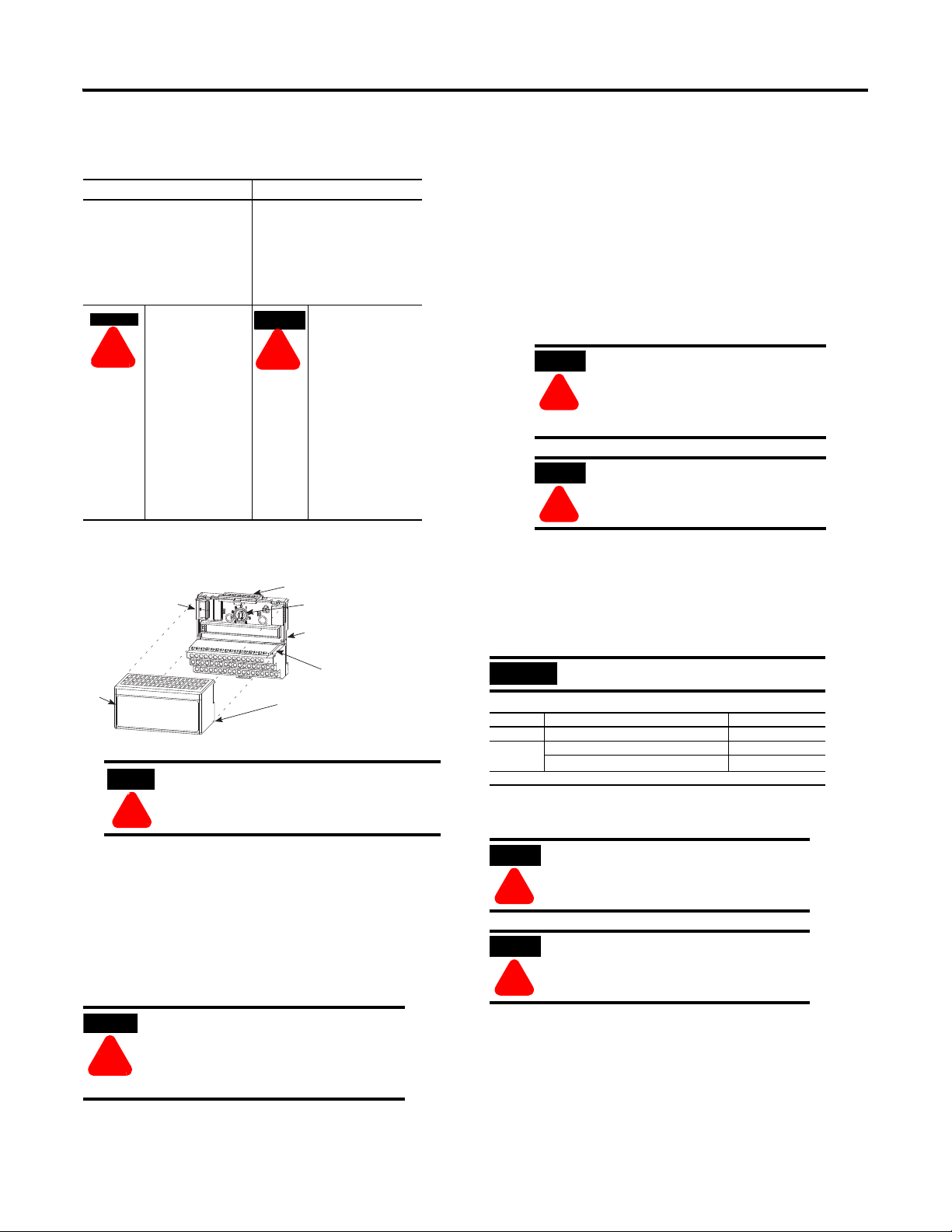
4. Position the module (4) with its alignment bar (5) aligned with the
groove (6) on the terminal base.
5. Press firmly and evenly to seat the module in the terminal base unit.
The module is seated when the latching mechanism (7) is locked into
the module.
Connecting Wiring for 1794-TB2, -TB3, -TB3S, -TB3T and -TB3TS Terminal Base Units
1. Connect individual high and low signal wiring to numbered terminals
on the 0-15 row (A) as indicated in the table. Use Belden 8761 cable
for mV signal wiring, or the appropriate thermocouple wire for your
thermocouples. (For more accurate readings in mV mode, use the
1794-TB3T or -TB3TS terminal base unit.)
The thermocouple/mV and RTD modules
do not receive power from the
backplane. +24V dc power must be
applied to the modules. If power is not
applied, the module position will appear
to the adapter as an empty slot in your
chassis.
You must power this module from the
same power supply that supplies the
adapter module, so they both power up
at the same time. You must cycle power
for the adapter to recognize this module.
2. Connect individual channel signal returns to the associated terminal
on row (B) as shown in the wiring table.
During mounting of all devices, be sure that all
debris (metal chips, wire strands, etc.) is kept from
falling into the module. Debris that falls into the
module could cause damage on power up.
The module mounts on a 1794 terminal base.
1. Rotate the keyswitch (1) on the terminal base (2) clockwise to position
3 as required for this type of module.
2. Make certain the flexbus connector (3) is pushed all the way to the left
to connect with the neighboring terminal base/adapter. You cannot
install the module unless the connector is fully extended.
3. Make sure the pins on the bottom of the module are straight so they
will align properly with the connector in the terminal base.
If you remove or insert the module while the
backplane power is on, an electrical arc can
occur. This could cause an explosion in
hazardous location installations. Be sure that
power is removed or the area is nonhazardous
before proceeding.
Publication 1794-IN021D-EN-P - August 2003
3. Connect individual channel shield returns to the associated terminal
on row (B) for 1794-TB3 or -TB3S or row (C) for the 1794-TB3T or
-TB3TS as shown in the wiring table..
Use the following Belden cables for connecting the
RTD to the terminal base unit.
RTD Type Length of Run/Humidity Level Belden Cable Number
2-wire Not applicable 9501
3-wire Less than 100ft (30.5m) with norma l humidity 9533
Over 100ft (30.5m) or high humidity
1 Greater than 55% for more than 8 hours.
4. Connect +24V dc power to terminal 34 on the 34-51 row (C).
5. Connect 24V dc common to terminal 16 on the 16-33 row (B).
To reduce susceptibility to noise, power
analog modules and digital modules from
separate power supplies. Do not exceed a
length of 9.8 ft (3m) for dc power cabling.
Do not daisy chain power or ground from this
terminal base unit to any ac or dc digital
module terminal base units.
6. 1794-IT8 only: On 1794-TB3T or -TB3TS terminal base units,
connect cold junction compensation (CJC) wiring to terminals 36, 37
and 38 for inputs 0-3, and terminals 47, 48 and 49 for inputs 4-7.
Connect the tail of the CJC to any of the associated thermocouple
input terminals: 0 thru 7 for CJC connected to terminals 36, 37 and
38; or 8 thru 15 for CJC connected to terminals 47, 48 and 49.
The tail of the CJC shares a terminal with an input.
1
83503
Page 3

3
17 18 19 20 21 22 23 24 25 26 27 28 29 30 31 32 33
0 1 2 3 4 5 6 7 8 9 10 11 12 13 14 15
16
12 3456 7 891011121314150
35 36 37 38 39 40 41 42 43 44 45 46 47 48 49 50 51
34
1794-TB2, TB3, -TB3T
0-15
34-51
16-33
A
B
C
Shaded terminals not included on 1794-TB2 terminal base unit.
17 18 19 20 21 22 23 24 25 26 27 28 29 30 31 32 33
0 1 2 3 4 5 6 7 8 9 10 11 12 13 14 15
16
12 3456 7 891011121314150
35 36 37 38 39 40 41 42 43 44 45 46 47 48 49 50 51
34
1794-TB3
0 -15
34-51
16-33
4-Wire RTD 2-Wire RTD3-Wire RTD
Clip or tieback
4th lead.
Attention: Keep exposed area of inner conductor as short as possible.
A
B
C
When using a 2-wire RTD, jumper the signal return to the low signal terminal.
17 18 19 20 21 22 23 24 25 26 27 28 29 30 31 32 33
0 1 2 3 4 5 6 7 8 9 10 11 12 13 14 15
16
1 2 3 4 5 6 7 8 9 10 11 12 13 14 150
35 36 37 38 39 40 41 42 43 44 45 46 47 48 49 50 51
34
1794-TB3 shown
0 –15
34–51
16–33
+
–
Millivolt input
Channel 1
Millivolt
Source
Channel 0 (T erminals 0, 1 and 17)
For more accurate readings, use the 1794-TB3T for mV measurement.
7. If daisychaining power to the next terminal base, connect a jumper
from terminal 51 (+V dc) on this base unit to the +V terminal on the
next base unit.
8. If continuing dc common to the next base unit, connect a jumper
from terminal 33 (common) on this base unit to the COM (return)
terminal on the next base unit.
Wiring Connections for the Thermocouple/RTD Module
1794-TB2, -TB3 and -TB3S Terminal Base Units
RTD or mV
Channel
High
Signal
Terminal
(H) or (+)
0 A-0 A-1 B-17 B-18
1 A-2 A-3 B-19 B-20
2 A-4 A-5 B-21 B-22
3 A-6 A-7 B-23 B-24
4 A-8 A-9 B-25 B-26
5 A-10 A-11 B-27 B-28
6 A-12 A-13 B-29 B-30
7 A-14 A-15 B-31 B-32
24V dc Common B-16 thru 33
+24V dc Power -TB3, -TB3S (C-34 thru C-51); -TB2 (C-34 & C-51)
1 When using a 2-wire RTD, jumper the signal return to the low signal
terminal.
RTD, mV or
Thermocouple
Channel
1794-TB3T and -TB3TS Terminal Base Units
1
High Signal
Terminal
(H) or (+)
0 A-0 A-1 B-17 C-39
1 A-2 A-3 B-19 C-40
2 A-4 A-5 B-21 C-41
3 A-6 A-7 B-23 C-42
4 A-8 A-9 B-25 C-43
5 A-10 A-11 B-27 C-44
6 A-12 A-13 B-29 C-45
7 A-14 A-15 B-31 C-46
1 Terminals 36, 37 and 38 and 47, 48 and 49 are for cold junction compensation only,
(with 38 and 47 chassis GND).
2 Terminals 39 to 46 are chassis ground.
Low
Signal
Ter mi na l
(L) or (-)
Low Signal
Terminal
(L) or (-)
Signal
Return
(-IR8
only)
Signal
Return
(-IR8 only)
Shield
1
Return
Shield
Return
Example of 2, 3 and 4-wire RTD Wiring to a 1794-TB3
Terminal Base Unit
Example of 2, 3 and 4-wire RTD Wiring to a 1794-TB3T
Terminal Base Unit
12 3456 7 891011121314150
0 1 2 3 4 5 6 7 8 9 10 11 12 13 14 15
17 18 19 20 21 22 23 24 25 26 27 28 29 30 31 32 33
16
35 36 37 38 39 40 41 42 43 44 45 46 47 48 49 50 51
34
1794-TB3T
Clip or tieback
4th lead.
Attention: Keep exposed area of inner conductor as short as possible.
4-Wire RTD 2-Wire RTD3-Wire RTD
0 -15
16-33
34-51
A
B
C
Example of Thermocouple Wiring to a 1794-TB3T
Ter min a l Bas e Uni t
12 34567891011121314150
0 1 2 3 4 5 6 7 8 9 10 11 12 13 14 15
17 18 19 20 21 22 23 24 25 26 27 28 29 30 31 32 33
16
35 36 37 38 39 40 41 42 43 44 45 46 47 48 49 50 51
34
CJC CJC
+
_
2
Example of Grounded Thermocouple Wiring to a
1794-TB3T
Ch. 4-7Ch 0-3
CJC kit Cat. No.
1794-CJC2/A
(contains 2 CJCs)
Channel 0 (Terminals 0 and 1 with shield to 39)
0 -15
16 - 33
34 - 51
A
B
C
1794-TB3T Terminal Base Unit
12 3456 7 891011121314150
0 1 2 3 4 5 6 7 8 9 10 11 12 13 14 15
17 18 19 20 21 22 23 24 25 26 27 28 29 30 31 32 33
16
35 36 37 38 39 40 41 42 43 44 45 46 47 48 49 50 51
34
CJC CJC
+
_
When using grounded thermocouples, and the error is off the same
amount on each thermocouple, connect terminal 16 to ground, and
connect the thermocouple ground to the same ground,
1794-TB3T
Channel 0
(Terminals 0 and 1
with shield to 39)
CJC kit Cat. No.
1794-CJC2/A
(contains 2 CJCs)
Ch. 4-7Ch 0-3
0 -15
16 - 33
34 - 51
A
B
C
Example of Millivolt Wiring to a 1794-TB3, -TB3S or
-TB3T Terminal
Base Unit
Publication 1794-IN021D-EN-P - August 2003
Page 4

4
Block Transfer Read and Write
The following block transfer read and write word bit information is presented
for experienced users only. Refer to the user manuals (publication
1794-UM004 for the RTD or 1794-UM007 for TC/mV) for these products for
complete information on programming and configuring your modules.
Input Map (Read) for 1794-IR8 and 1794-IT8
Dec. 15 14 13 12 11 10 9 0 7 6 5 4 3 2 1 0
Oct. 17 16 15 14 13 12 11 10 7 6 5 4 3 2 1 0
Word 0Reserved
1 Channel 0 Input Data
2 Channel 1 Input Data
3 Channel 2 Input Data
4 Channel 3 Input Data
5 Channel 4 Input Data
6 Channel 5 Input Data
7 Channel 6 Input Data
8 Channel 7 Input Data
9 Overrange Alarm Bits (channel 0 = bit 8, etc.) Underrange Alarm Bits (channel 0 = bit 0, etc.
0 0 0 0 0 Bad
10
(-IT8)
0 0 0 0 0 Bad
10
(-IR8)
Temperature and resistance data is returned with an implied decimal point. For
example, a temperature data of 1779 is 177.9°. Resistance data of 2034 is
203.4Ω. mV data is returned with an implied decimal point of 2 decimal points.
for example, 7500 is 75mV.
Output Map (Write) for 1794-IR8 and 1794-IT8
Dec. 15 14 13 12 11 10 9 8 7 6 5 4 3 2 1 0
Oct. 17 16 15 14 13 12 11 10 7 6 5 4 3 2 1 0
IT8
8-Bit Calibration Mask Cal
Word 0
IR8
8-Bit Calibration Mask Cal
Word 0
Word 1 Thermocouple or RTD
Type Ch 3
Word 2 Thermocouple or RTD
Type Ch 7
Word 3 Reserved
Where: FDF = Fixed digital filter (TC only)
Enh = Enhanced mode (RTD only)
MDT = Module Data Type
Data Format for All Channels - Write Word 0
Bit 01 00
0 0 °C
0 1 °F
1 0 Bipolar counts scaled between -32767 to +32767
1 1 Unipolar counts scaled between 0 and 65535
0101 thru 1111 not used
Cal
Cal
Done
Cal
Cal
Done
Thermocouple or RTD
Type Ch 2
Thermocouple or RTD
Type Ch 6
Cal
Rng
Cal
RngRIUP
0 Diag.
Status Bits
Critical
Error Bits
Cal
Clk
Hi/
Lo
Cal
Clk
Hi/
Lo
Thermocouple or RTD
Type Ch 1
Thermocouple or RTD
Typ e Ch 5
Pwr UpBad
Pwr UpRes. 0 0
Filter Cutoff FDF MDT
Filter Cutoff Enh MDT
CJC
Struct
Over
Thermocouple or RTD
Type Ch 0
Thermocouple or RTD
Type Ch 4
CJC
Under
RTD Type - Write Word 1 and 2
RTD Type
Bit 03 02 01 00 Channel 0 (Write word 1)
Bit 07 06 05 04 Channel 1 (Write word 1)
Bit 11 10 09 08 Channel 2 (Write word 1)
Bit 15 14 13 12 Channel 3 (Write word 1)
Bit 03 02 01 00 Channel 4 (Write word 2)
Bit 07 06 05 04 Channel 5 (Write word 2)
Bit 11 10 09 08 Channel 6 (Write word 2)
Bit 15 14 13 12 Channel 7 (Write word 2)
0 0 0 0 Resistance (default = mV)
0 0 0 1 No sensor connected - do not scan
0 0 1 0
0 0 1 1
0 1 0 0
0 1 0 1
100Ω Pt α = 0.00385 Euro (-200 to +870°C)
100Ω Pt α = 0.003916 U .S. (-200 to +630°C)
200Ω Pt α = 0.00385 Euro (-200 to +630°C)
500Ω Pt α = 0.00385 Euro (-200 to +630°C)
0 1 1 0 Reserved
0 1 1 1 10Ω Copper (-200 to +260°C)
1 0 0 0 120Ω Nickel (-60 to +250°C)
1 0 0 1 100Ω Nickel (-60 to +250°C)
1 0 1 0 200Ω Nickel (-60 to +250°C)
1 0 1 1 500Ω Nickel (-60 to +250°C)
1 1 0 0 Reserved
Thermocouple Type - Write Word 1 and 2
Thermocouple Type Range
Bit 03 02 01 00 Channel 0 (Write word 1)
Bit 07 06 05 04 Channel 1 (Write word 1)
Bit 11 10 09 08 Channel 2 (Write word 1)
Bit 15 14 13 12 Channel 3 (Write word 1)
Bit 03 02 01 00 Channel 4 (Write word 2)
Bit 07 06 05 04 Channel 5 (Write word 2)
Bit 11 10 09 08 Channel 6 (Write word 2)
Bit 15 14 13 12 Channel 7 (Write word 2)
0 0 0 0 mV (default)
0 0 0 1 B 300 to 1800°C (572 to 3272°F)
0 0 1 0 E -270 to 1000°C (-454 to 1832°F)
0 0 1 1 J -210 to 1200°C (-346 to 2192°F)
0 1 0 0 K -270 to 1372°C (-454 to 2502°F)
0 1 0 1 R -50 to 1768°C (-58 to 3214°F)
0 1 1 0 S -50 to 1768°C (-58 to 3214°F)
0 1 1 1 T -270 to 400°C (-454 to 752°F)
1 0 0 0 C 0 to 2315°C (32 to 4199°F)
1 0 0 1 N -270 to 1300°C (-450 to 2372 °F)
1 0 1 0 TXK/XK(L) -200 to 800°C (- 328 to 1472°F)
1 0 1 1 Reserved
1 1 0 0 Module reports cold junction sen sor temperature for channels 00-03
1 1 0 1 Module reports cold junction sen sor temperature for channels 04-07
1 1 1 0 Reserved
1 1 1 1 No input device connected - do not scan
Publication 1794-IN021D-EN-P - August 2003
Page 5

5
19.2
24.0
31.2
Safe operating area
The area within the curve represents the safe operating range for the module
under various conditions of user supplied 24V dc supply voltages and ambient
temperatures.
0˚C 25˚C 40˚C 50˚C 55˚C
User Applied 24V dc Supply
Ambient Temperature
Specifications
Specifications 1794-IT8 1794-IR8
Number of Inputs 8 ch annels
Module Location Cat. No. 1794-TB2, -TB3, -TB3S, -TB3 T and -TB3TS Terminal Base Units
Nominal Input
Ranges
Supported
Thermocouple Types
(1794-IT8 only)
Supported RTDs
(1794-IR8 only)
RTD Excitation
Current
Resolution 16 bits (2.384μV typical) 16 bits across 435 ohms
Accuracy Refer to “Calculating the Accuracy”
Common Mode
Rejection
Common Mode Input
Range
Isolation Voltage Tested at 850V dc for 1s from inputs and user power to logic side
Data Format 16-bit 2’s complement or offset binary (unipolar)
Normal Mode Noise
Rejection
Input Offset Drift
w/Temperature
Gain Drift w/Temp. 10ppm/°C maximum Normal mode: 20ppm/°C max.
Channel Bandwidth 0-2.62Hz (-3db)
Settling time to 100%
of final value
System Throughput 325ms (1 channel scanned),
Open TC/RTD Circuit
Detection
Open TC/RTD
Detection Time
Overvoltage
Capability
Overall Drift with
Temperature
Cold Junction
Compensation
Channel to channel
isolation
Indicators 1 red/green power status indicator
Flexbus Current 20mA
Power Dissipation 3.0W maximum @ 31.2V dc
Thermal Dissipation Maximum 10.2 BTU/hr @ 31.2V dc
Keyswitch Position 3
General Specifications
External dc Power
Supply
Voltage Range
Supply Current
Dimensions (with
module installed)
Environmental Conditions
-76.5 to +76.5mV 1 to 433 ohms
Type Range °C Range °F
B 300 to 1800°C (572 to 3272°F)
C 0 to 2315°C (32 to 4199°F)
E -270 to 1000°C (-454 to 1832°F)
J -210 to 1200°C (-346 to 2192°F)
K -270 to 1372°C (-454 to 2502°F)
TXK/XK(L) -200 to 800°C (-328 to 1472°F)
N -270 to 1300°C (-454 to 2372°F)
R - 50 to 1768°C (-58 to 3214°F)
S - 50 to 1768°C (-58 to 3214°F)
T -270 to 400°C (-454 to 752°F)
Resistance
100Ω Pt α = 0.00385 Euro (-200 to +870°C)
100Ω Pt α = 0.003916 U .S. (-200 to +630°C)
200Ω Pt α = 0.00385 Euro (-200 to +400°C)
500Ω Pt α = 0.00385 Euro (-200 to +630°C)
100Ω Nickel α = 0.00618 (-60 to +250°C)
120Ω Nickel α = 0.00672 (-60 to +250°C)
200Ω Nickel α = 0.00618 (-60 to +250°C)
500Ω Nickel α = 0.00618 (-60 to +250°C)
10Ω Copper α = 0.00427 (-200 to +260°C)
718.36μA
section in Appendix A of the user
manual (1794-UM007)
-115db @ 60Hz; -100db @ 50Hz -120db @ 60Hz; -100db @ 50Hz with
+10V maximum 0V between channels (common
-60db @ 60Hz -60db @ 60Hz for A/D filter cutoff @
Without calibration, at low humidity:
Normal mode: 0.05% full scale (max)
Enh. mode: 0.01% full scale (typical)
A/D filter cutoff @ 10Hz
return)
10Hz
+6mV/°C maximum 1.5 milliohm/°C maximum
Enhanced mode: 10ppm/°C max.
Available at system throughput rate
programmable to 28ms
2.6s (8 channels scanned),
programmable to 224ms
Normal mode - 325ms (1 channel
scanned), programmable to 28ms
2.6s (8 channels scanned),
programmable to 224ms
Enhanced mode - programmable
from 56 to 650ms/channel - 650ms
(1 channel scanned), 2.925s (8
channels scanned)
Out of range reading (upscale)
Available at system throughput rate
35V dc, 25V ac continuous at 25°C
50ppm/°C of span (maximum)
Range: 0 to 70°C
A-B catalog number 1794-CJC2
+10V 0V
24V dc nominal
19.2 to 31.2V dc (includes 5% ac ripple)
19.2 to 31.2V dc for ambient tempera tures < 40°C
24V dc maximum for ambient temperatu res = 55°C
See derating curve
150mA @ 24V dc
31.8H x 3.7W x 2.1D inches
45.7H x 94W x 53.3D mm
Operating
Temperature
Storage
Temperature
Relative Humidity IEC 60068-2-30 (Test Db, Un-packaged Non-operating
Vibration IEC60068-2-6 (Test Fc, Operating):
Shock IEC60068-2-27 (Test Ea, Unpackaged shock):
Emissions CISPR 11:
ESD Immunity IEC 61000-4-2:
Radiated RF
Immunity
EFT/B Immunity IEC 61000-4-4:
Surge Transient
Immunity
Conducted RF
Immunity
IEC 60068-2-1 (Test Ad, Operating Cold),
IEC 60068-2-2 (Test Bd, Operating Dry Heat),
IEC 60068-2-14 (Test Nb, Operating Thermal Shock):
0 to 55°C (32 to 131°F)
IEC 60068-2-1 (Test Ab, Un-packaged Non-operating Cold),
IEC 60068-2-2 (Test Bb, Un-packaged Non-operating Dry Heat),
IEC 60068-2-14 (Test Na, Un-packaged Non-operating Thermal Shock):
–40 to 85°C (–40 to 185°F)
Damp Heat):
5 to 95% non-condensing
5g @ 10-500Hz
Operating 30g
Non-operating 50g
Group 1, Class A (with appropriate e nclosure)
4kV contact discharges
8kV air discharges
IEC 61000-4-3:
10V/m with 1kHz sine-wave 80%AM from 30M Hz to 1000MHz
±2kV at 5kHz on signal ports
IEC 61000-4-5:
+2kV line-earth(CM) on shielded ports
IEC 61000-4-6:
10Vrms with 1kHz sine-wave 80%AM from 150kHz to 30MHz
Enclosure Type Rating None (open-style)
Signal Conductors
Thermocouple
Millivolt
2
Category
Power Conductors
Wire Size
2
Category
Certifications (when
product is marked)
1 Refer to thermocouple manufacturer for proper thermocouple extension.
2 You use this category information for planning conductor routing as described in Allen-Bradley
publication 1770-4.1, Industrial Automation Wiring and Grounding Guidelines.
3 For the latest up-to-date information, see the Product Certification link at www.ab.com for Declarations of
Conformity, Certificates and other certification details. For notification of any additional release notes, refer to
www.ab.com/manuals/.
Thermocouple - Use appropriate
shielded thermocouple wire
Belden 8761
2
12AWG (4mm2) stranded copper wire rated at 75°C or higher
3/64 inch (1.2mm) insulation maximum
2
UL UL Listed Industr ial Control Equipment
3
C-UL-US UL Listed Industrial Control Equipment, cert ified for US and Canada
(1794-IT8)
C-UL-US UL listed for Class I, Division 2, Groups A, B, C and D Hazardous
locations, certified for US and Canada (1794-IT8)
CSA CSA certified Process Control Equipment
CSA CSA certified for Class I, Division 2, Groups A, B, C and D
Hazardous locations
EEx3European Union 94/9/EEC ATEX Directive, compliant with:
EN 50021; Potentially Explosive Atmospheres,
Protection “n” (Zone 2)
CE3 European Union 89/336/EEC EMC Directive,
compliant with:
EN 61000-6-4; Industrial Emissions
EN 50082-2; Industrial Immunit y
EN 61326; Meas./Control/Lab., Industrial Requirements
EN 61000-6-2; Industrial Immuni ty
C-Tick3Australian Radiocommunications Act com pliant with
AS/NZS CISPR 11, Industrial Emissions
2-wire -Belden 9501
3-wire, less than 100ft with normal
1
humidity - Belden 9533
3-wire, greater than 100ft or nor mal
humidity (>55°C for > 8 hrs) - Belden
83503
Derating Curve
Publication 1794-IN021D-EN-P - August 2003
Page 6

Publication 1794-IN021D-EN-P - August 2003 6 PN 957782-83
Supersedes Publication 1794-IN021C-EN-P - April 2002 and 1794-IN022B-EN-P - April 2002 Copyright © 2003 Rockwell Automation, Inc . All rights reserved. Printed in the U.S.A.
 Loading...