

Page 1
Installation Instructions
FLEX I/O 4 Channel Pulse Counter Module
Cat. No. 1794-IP4 Series B
Important User Information
Solid state equipment has operational characteristics differing from those of
electromechanical equipment. Safety Guidelines for the Application, Installation and
Maintenance of Solid State Controls (Publication SGI-1.1 available from your local Rockwell
Automation sales office or online at http://www.ab.com/manuals/gi) describes some
important differences between solid state equipment and hard-wired electromechanical
devices. Because of this difference, and also because of the wide variety of uses for solid state
equipment, all persons responsible for applying this equipment must satisfy themselves that
each intended application of this equipment is acceptable.
In no event will Rockwell Automation, Inc. be responsible or liable for indirect or consequential
damages resulting from the use or application of this equipment.
The examples and diagrams in this manual are included solely for illustrative purposes.
Because of the many variables and requirements associated with any particular installation,
Rockwell Automation, Inc. cannot assume responsibility or liability for actual use based on the
examples and diagrams.
No patent liability is assumed by Rockwell Automation, Inc. with respect to use of information,
circuits, equipment, or software described in this manual.
Reproduction of the contents of this manual, in whole or in part, without written permission of
Rockwell Automation, Inc. is prohibited.
Throughout this manual we use notes to make you aware of safety considerations.
WARNING
IMPORTANT
ATTENTION
ATTENTION
Identifies information about practices or circumstances that can cause
an explosion in a hazardous environment, which may lead to personal
injury or death, property damage, or economic loss.
Identifies information that is critical for successful application and
understanding of the product.
Identifies information about practices or circumstances that can lead to
personal injury or death, property damage, or economic loss. Attentions
help you:
• identify a hazard
• avoid a hazard
• recognize the consequence
Environment and Enclosure
This equipment is intended for use in a Pollution Degree 2 industrial
environment, in overvoltage Category II applications (as defined in
IEC publication 60664-1), at altitudes up to 2000 meters without
derating.
This equipment is considered Group 1, Class A industrial equipment
according to IEC/CISPR Publication 11. Without appropriate
precautions, there may be potential difficulties ensuring
electromagnetic compatibility in other environments due to conducted
as well as radiated disturbance.
This equipment is supplied as "open type" equipment. It must be
mounted within an enclosure that is suitably designed for those specific
environmental conditions that will be present and appropriately
designed to prevent personal injury resulting from accessibility to live
parts. The interior of the enclosure must be accessible only by the use
of a tool. Subsequent sections of this publication may contain
additional infor mation regarding specific enclosure type ratings that are
required to comply with certain product safety certifications.
See NEMA Standards publication 250 and IEC publication 60529, as
applicable, for explanations of the degrees of protection provided by
different types of enclosure. Also, see the appropriate sections in this
publication, as well as the Allen-Bradley publication 1770-4.1
("Industrial Automation Wiring and Grounding Guidelines"), for
additional installation requirements pertaining to this equipment.
WARNING
WARNING
ATTENTION
ATTENTION
When you insert or remove the module while backplane power is
on, an electrical arc can occur. This could cause an explosion in
hazardous location installations. Be sure that power is removed or
the area is nonhazardous before proceeding. Repeated electrical
arcing causes excessive wear to contacts on both the module and its
mating connector. Worn contacts may create electrical resistance
that can affect module operation.
If you connect or disconnect wiring while the field-side power is
on, an electrical arc can occur. This could cause an explosion in
hazardous location installations. Be sure that power is removed or
the area is nonhazardous before proceeding.
FLEX I/O is grounded through the DIN rail to chassis ground. Use
zinc plated yellow-chromate steel DIN rail to assure proper
grounding. The use of other DIN rail materials (e.g. aluminum,
plastic, etc.) that can corrode, oxidize, or are poor conductors, can
result in improper or inter mittent grounding.
Preventing Electrostatic Discharge
This equipment is sensitive to electrostatic discharge, which can
cause internal damage and affect normal operation. Follow these
guidelines when you handle this equipment:
• Touch a grounded object to discharge potential static.
• Wear an approved grounding wriststrap.
• Do not touch connectors or pins on component boards.
• Do not touch circuit components inside the equipment.
• If available, use a static-safe workstation.
North American Hazardous Location Approval
The following information applies when operating
this equipment in hazardous locations:
Products marked “CL I, DIV 2, GP A, B, C, D” are suita ble
for use in Clas s I Division 2 Groups A, B , C, D, Hazardous
Locations and nonhazardous locations only. Each
product is supplied with markings on the rating
nameplate indicating the hazardous location
temperature code. When combining products within a
system, the mos t adverse temperatur e code (lowest “T”
number) may be used to help determine the overall
temperature code of the system. Combinations of
equipment in your system are subject to investigation by
the local Autho rity Having Jurisdictio n at the time of
installation.
WARNING
EXPLOSION HAZARD
• Do not disc onnect
equipment unles s power has
been removed or the area is
known to be no nhazardous.
• Do not disc onnect
connections to this equipment
unless power has been
removed or the area is know n
to be nonhazardous. Secure
any external co nnections that
mate to this equipment by
using screws, slidin g latches,
threaded conn ectors, or other
means provided with this
product.
• Substitu tion of components
may impair suitability for Class
I,
Division 2.
• If this product contains
batteries, they m ust only be
changed in an area known to
be nonhazardous.
Informations sur l’utilisation de cet équipement en
environnements dangereux :
Les produits marqués "CL I, DIV 2, GP A, B, C, D" ne
conviennent qu’à un e utilisation en environnements de
Classe I Divisio n 2 Groupes A, B, C, D dangereux et non
dangereux. Ch aque produit est livré avec des marquages
sur sa plaque d’id entification qui indiquent le code de
température pour les environnements dangereux. Lorsque
plusieurs prod uits sont combinés dans u n système, le
code de tempé rature le plus défavorab le (code de
température le plus faible) peut être utilisé pour
déterminer le code de température global du système. Les
combinaisons d’ équipements dans le s ystème sont
sujettes à inspection par les autorités locales qua lifiées
au moment de l’ installation.
AVERTISSEMENT
RISQUE D’EXPLOSION
• Couper le courant ou s’assurer
que l’environnement est classé
non dangereu x avant de
débrancher l'équipement.
• Couper le courant ou s'assurer
que l’environnement est classé
non dangereu x avant de
débrancher les connecteurs. Fixer
tous les connecteurs externes
reliés à cet éq uipement à l'aide
de vis, loquets coulissants,
connecteurs filetés ou autres
moyens fourni s avec ce produit.
• La substitut ion de composants
peut rendre cet équipement
inadapté à un e utilisation en
environnement de Classe I,
Division 2.
• S’assurer que l’environnement
est classé non dangereux avant
de changer les piles.
Publication 1794-IN064D-EN-P - March 2005
Page 2
2
Even Numbered I/O Terminals 0 thru 14
+
C
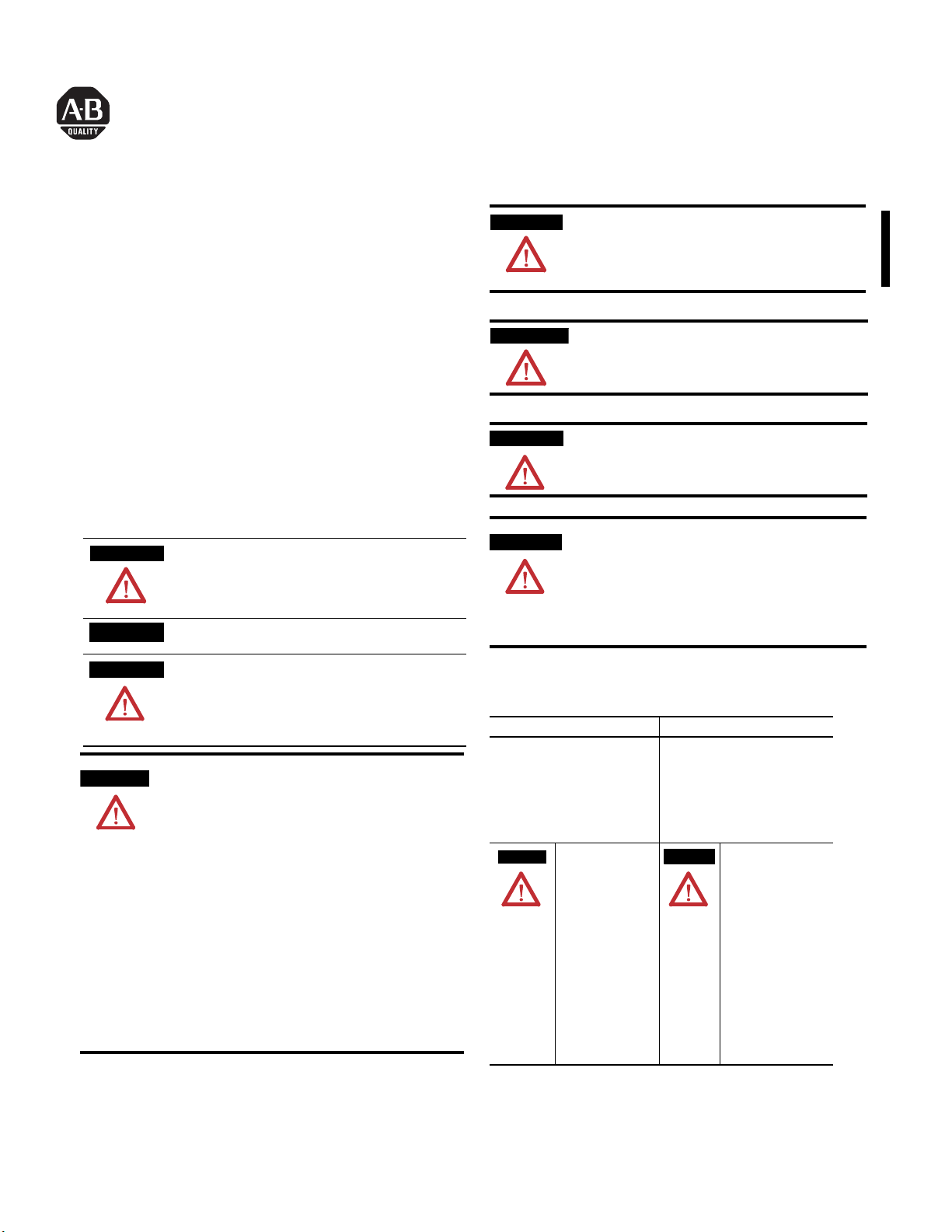
Installing Your Pulse Counter Module
7
3
1
2
6
4
The module mounts on a 1794 terminal base.
ATTENTION
1. Rotate the keyswitch (1) on the terminal base (2) clockwise to position
1 as required for this type of module.
2. Make certain the flexbus connector (3) is pushed all the way to the left
to connect with the neighboring termbase/adapter. You cannot install
the module unless the connector is fully extended.
3. Make sure the pins on the bottom of the module are straight so they
will align properly with the connector in the terminal base.
WARNING
4. Position the module (4) with its alignment bar (5) aligned with the
groove (6) on the terminal base.
5. Press firmly and evenly to seat the module in the terminal base unit.
The module is seated when the latching mechanism (7) is locked into
the module.
During mounting of all devices, be sure that all debris
(metal chips, wire strands, etc.) is kept from falling into
the module. Debris that falls into the module could
cause damage on power up.
If you remove or insert the module while the backplane
power is on, an electrical arc can occur. This could cause
an explosion in hazardous location installations. Be sure
that power is removed or the area is nonhazardous before
proceeding.
5
Connecting Wiring for the 1794-IP4 (using a 1794-TB2, -TB3 or
-TB3S terminal base unit)
1. Connect individual input wiring (N, N) or (D, D) for each channel to
numbered terminals on the 0-15 row (A) as indicated in the table
below.
5. If daisychaining power to the next terminal base, connect a jumper
from terminal 51 (+V dc) on this base unit to terminal 34 on the next
base unit.
6. If continuing dc common to the next base unit, connect a jumper
from terminal 33 (common) on this base unit to terminal 16 on the
next base unit.
0 1 2 3 4 5 6 7 8 9 10 11 12 13 14 15
17 18 19 20 21 22 23 24 25 26 27 28 29 30 31 32 33
16
-V
Common
35 36 37 38 39 40 41 42 43 44 45 46 47 48 49 50 51
34
Voltage
In +V
-V (Supply Common) = Terminals B16 and B33
+V (Supply +Voltage) = Terminals C34 and C51
(Use B33 and C51 for daisy-chaining to next terminal base unit.)
Inputs
Commons
Voltage
A
B
-V
Common
Voltage
Out +V
(1794-TB3 shown)
C
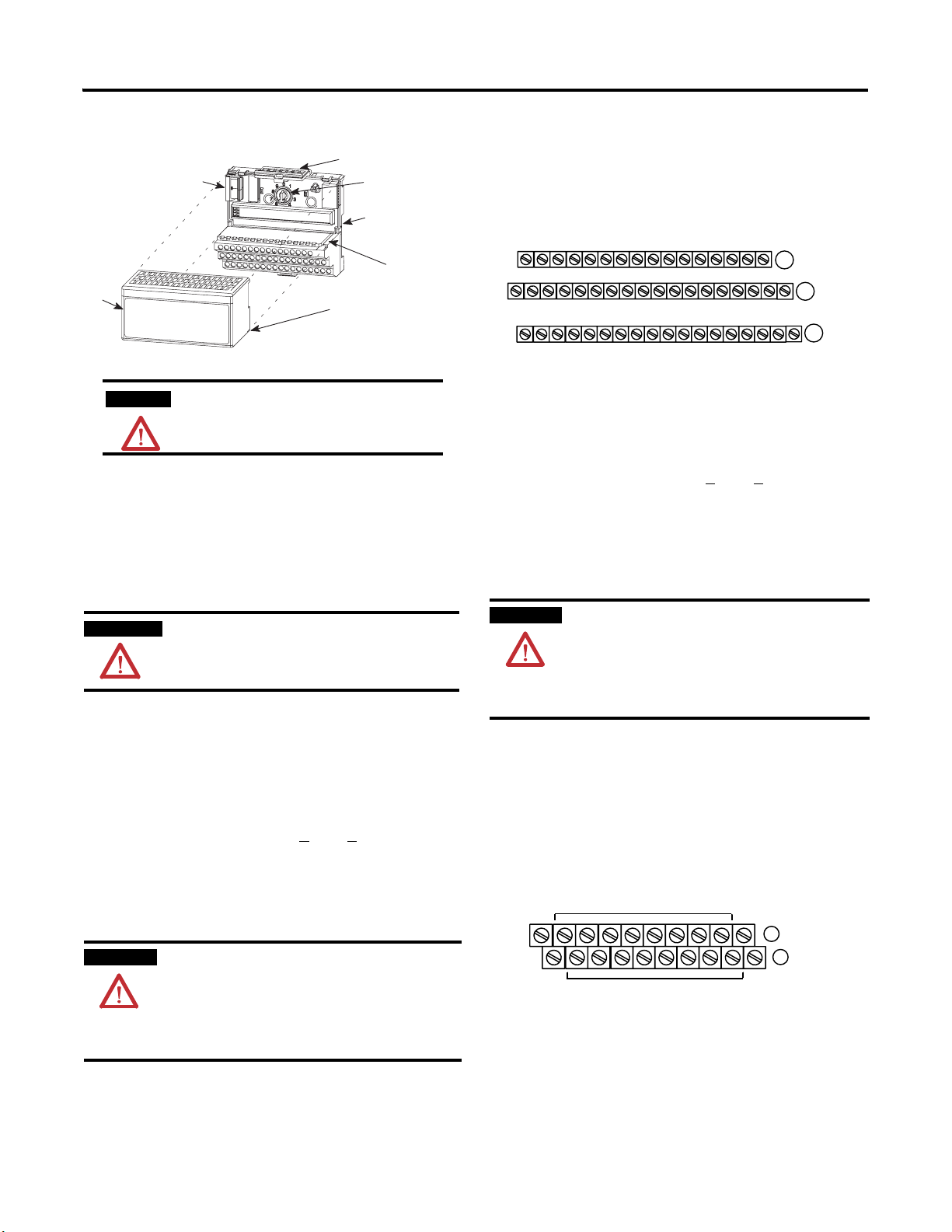
Connecting Wiring for the 1794-IP4 (using a 1794-TBN terminal
base unit)
1. Connect individual input wiring (N, N) or (D, D) for each channel to
the even-numbered terminals on the 16-33 row (B) as indicated in the
table below.
2. Connect the associated input common to the corresponding
odd-numbered terminal on the 34-51 row (C) for each input as
indicated in the table below.
ATTENTION
3. Connect +V dc power to terminal 34 on the 34-51 row (C).
4. Connect dc return to terminal 16 on the 16-33 row (B).
5. If daisychaining power to the next terminal base, connect a jumper
from terminal 51 (+V dc) on this base unit to terminal 34 on the next
base unit.
6. If continuing dc common to the next base unit, connect a jumper
from terminal 33 (common) on this base unit to terminal 16 on the
next base unit.
Do not connect maximum input voltage simultaneously to
all inputs if the module ambient temperature is expected to
exceed 40°C.
If the ambient temperature is expected to continuously
exceed 40°C, you must limit the input voltage using an
external resistor on each input. A 1kW resistor effectively
limits a 24V sensor signal to about 15V at the input. Do not
limit the input to less than 6V.
2. Connect the associated input common to the corresponding terminal
on the 16-33 row (B) for each input as indicated in the table below.
ATTENTION
Do not connect maximum input voltage simultaneously to
all inputs if the module ambient temperature is expected to
exceed 40°C.
If the ambient temperature is expected to continuously
exceed 40°C, you must limit the input voltage using an
external resistor on each input. A 1kΩ resistor effectively
limits a 24V sensor signal to about 15V at the input. Do not
COM
16
34
+V
V = Terminals C34 and C51
OM (-V) = Terminals B16 and B33
4
2
0
1
6789101112
3
5
Odd Numbered I/O Terminals 1 thru 15
COM
14
33
13
15
B
51
C
+V
limit the input to less than 6V.
3. Connect +V dc power to terminal 34 on the 34-51 row (C).
4. Connect dc return to terminal 16 on the 16-33 row (B).
Publication 1794-IN064D-EN-P - March 2005
Page 3

3
Wiring Connections for the 1794-IP4
Channel Signal
Name
1
16-bit Period Time Measurement
0 N A-0 B-17 C-35 B-0
N A-1 B-18 C-36 B-1
1 N A-2 B-19 C-37 B-2
N A-3 B-20 C-38 B-3
2 N A-4 B-21 C-39 B-4
N A-5 B-22 C-40 B-5
3 N A-6 B-23 C-41 B-6
N A-7 B-24 C-42 B-7
32-bit Period Time Measurement
0 D A-8 B-25 C-43 B-8
D A-9 B-26 C-44 B-9
1 D A-10 B-27 C-45 B-10
D A-11 B-28 C-46 B-11
2 D A-12 B-29 C-47 B-12
D A-13 B-30 C-48 B-13
3 D A-14 B-31 C-49 B-14
D A-15 B-32 C-50 B-15
0V dc Terminals 16 thru 33 (1794--TB2, -TB3,
12/24V dc Terminals 34 and 51 (1794-TB2)
1 Any unused signals have t o be connected to the associated common.
2 Auxiliary terminal blocks are required when us ing these terminal base units.
1794-TB2, -TB3, -TB3S
Signal 0V dc
COM
12...24V dcSignal
-TB3S)
Terminals 34 thru 51 (1794-TB3, -TB3S)
Example of 16-bit Period Time Measurement and 16-bit
Accumulating Pulse Counter Wiring (4 channels)
Accumulating Pulse Counter
Channel 3
Channel 2
Channel 1
Channel 0
N
N
N
N
N
N
N
N
1794-TBN
Terminals
16 and 33
Terminals
34 and 51
Example of 32-bit Period Time Measurement Wiring
(4 channels)
2
32-bit period time measurement
Channel 3
Channel 2
Channel 1
Channel 0
Power Supply
NOTE: To reduce noise, attach N to 0V dc
Input (read) Image
Dec. 15 14 13 12 11 10 9 8 7 6 5 4 3 2 1 0
Oct. 17 16 15 14 13 12 11 10 7 6 5 4 3 2 1 0
0 Reserved
1 Counter 00 - 16-bit period measurement for channel 0
2 Counter 01 - pulse counter for channel 0 - 16-bit pulse counting
1 32-bit period measurement for channel 0
2 32-bit period measurement for channel 0
3 Counter 10 - 16-bit period measurement for channel 1
4 Counter 11 - pulse counter for channel 1 - 16-bit pulse counting
3 32-bit period measurement for channel 1
4 32-bit period measurement for channel 1
5 Counter 20 - 16-bit period measurement for channel 2
6 Counter 21 - pulse counter for channel 2 - 16-bit pulse counting
5 32-bit period measurement for channel 2
6 32-bit period measurement for channel 2
7 Counter 30 - 16-bit period measurement for channel 3
8 Counter 31 - pulse counter for channel 3 - 16-bit pulse counting
7 32-bit period measurement for channel 3
8 32-bit period measurement for channel 3
9 Readback of Co ntrol Word 2
10 Revidion Read - software version code
Where M = Measurement Ready bit - positive edge measurement ready for the respective channel
Output/Configuration Image
D
D
D
D
D
D
D
D
9
11 12 13
8
10
0
Signal Inputs
External
0V dc
12/24V dc
12/24V dc
Reserved R
RD = Reset done
8 9 10 11 12 13 14 15
24 25 26 27 28 29 30 31 32
16
42 43 44 45 46 47 48 49 50
34
14 15
A
33
B
51
C
R
R
R
D
1
M3M2M1M
D
0
0
D
D
3
2
0
1
012345678
Signal Inputs
17 18 19 20 21 22 23 24 25 33
0V dc
12/24V dc
16
35 36 37 38 39 40 41 42
34
External
Power Supply
12/24V dc
NOTE: To reduce noise, attach N to 0V dc
Dec. 15 14 13 12 11 10 9 8 7 6 5 4 3 2 1 0
Oct. 17 16 15 14 13 12 11 10 7 6 5 4 3 2 1 0
673452
15
A
B
51
C
0 Control Word 0 - selects the measur e function
1 Control Word 1 - sets the clock freq uency and period multiple
2 Control Word 2 - sets the start of a new measurement
3 Not used
Publication 1794-IN064D-EN-P - March 2005
Page 4

4
Description of Control Word 0
Bit Description
Bit 0 Pulse Counting and period time measurement selection for Channel 0
0 = pulse counting and period time measurement selected - 16-bit
1 = period time measurement selected - 32-bit
Bit 01 Pulse Counting and period time measurement selection for Channel 1
0 = pulse counting and period time measurement selected - 16-bit
1 = period time measurement selected- 32-bit
Bit 02 Pulse Counting and period time measurement selection for Channel 2
0 = pulse counting and period time measurement selected - 16-bit
1 = period time measurement selected- 32-bit
Bit 03 Pulse Counting and period time measurement selection for Channel 3
0 = pulse counting and period time measurement selected - 16-bit
1 = period time measurement selected- 32-bit
Bit 04
Channel 0 - 0 = filter disabled; 1 = filter enabled
Bit 05
Channel 1 - 0 = filter disabled; 1 = filter enabled
Bit 06
Channel 2 - 0 = filter disabled; 1 = filter enabled
Bit 07
Channel 3 - 0 = filter disabled; 1 = filter enabled
Bits
09 08 Filter sample clock frequency and period (common to all
08-09
0 0 625kHz 1.6µs
0 1 312.5kHz 3.2µs
1 0 104.17kHz 9.6µs
1 1 7.8125kHz 128µs
Bits
Reserved
10-15
1
Use filter when the input waveform has slow rise/fall time or has high frequency noise on the
input waveform.
channels)
1
1
1
1
Filter Function Description
Use the filter in either 16-bit or 32-bit mode. Enable filter to use a triangular
shape waveform of frequencies as low as 1Hz. If the filter is not enabled, the
module will only function properly with input waveform of square shape.
Description of Control Word 2
Bit Description
00 Start new measurement - Channel 0 - when set, start new
measurement on positive edge
01 Start new measurement - Channel 1 - when set, start new
measurement on positive edge
02 Start new measurement - Channel 2 - when set, start new
measurement on positive edge
03 Start new measurement - Channel 3 - when set, start new
measurement on positive edge
04 Reset Counter, Channel 0 - a positive edge on this bit resets counter 01
05 Reset Counter, Channel 01- a positive edge on this bit resets counter 11
06 Reset Counter, Channel 2 - a positive edge on this bit resets counter 21
07 Reset Counter, Channel 3 - a positive edge on this bit resets counter 31
08-15 Reserved for factory use
Description of Control Word 2 Readback
Bit Description
00 Positive edge - Channel 0 - measurement ready
01 Positive edge - Channel 1 - measurement ready
02 Positive edge - Channel 2 - measurement ready
03 Positive edge - Channel 3 - measurement ready
04 Reset Counter, Channel 0 - a positive edge on this bit indicates counter 01
reset done
05 Reset Counter, Channel 1 - a positive edge on this bit indicates counter 11
reset done
06 Reset Counter, Channel 2 - a positive edge on this bit indicates counter 21
reset done
07 Reset Counter, Channel 3 - a positive edge on this bit indicates counter 31
reset done
08-15 Reserved for factory use
ATTENTION
Do not enable the filter with frequencies greater than
90kHz. A loss of counts may result.
Description of Control Word 1
Bit Description
00
Clock Frequency for period time measurement - Channel 0
0 = period time measurement with 10MHz internal clock selected
1 = period time measurement with 1MHz internal clock selected
01-03
03 02 01 Number of periods for measurement - Channel 0
0 0 0 1 period
0 0 1 2 period
0 1 0 4 period
0 1 1 8 period
1 0 0 16 period
1 0 1 32 period
1 1 0 64 period
1 1 1 128 period
04
Clock frequency for period time measurement - Channel 1 - refer to bit 00
05-07
Selection of number of periods for measurement - Channel 1 - see bits 01-03
08
Clock frequency for period time measurement - Channel 2 - refer to bit 00
09-11
Selection of number of periods for measurement - Channel 2 - see bits 01-03
12
Clock frequency for period time measurement - Channel 3 - refer to bit 00
13-15
Selection of number of periods for measurement - Channel 3 - see bits 01-03
Publication 1794-IN064D-EN-P - March 2005
Page 5

Specifications
Specifications Pulse Counter Module, Cat. No. 1794-IP4
Number of Inputs 4
Module Location Cat. No. 1794-TB2, -TB3, -TB3S, -TBN
Dimensions (with module
installed in base)
Imperial
Metric
Counting Frequency 100kHz maximum - Each signal condi tion must be stable fo r at least
Input Range Input ON
Input OFF
Input Current (typical) 3mA @ 6V dc
Data Format Period read in 1µs counts with 1 MHz internal clock selected;
Overflow Maximum period is 65 ms when 1 MHz internal clock selected;
Isolation Voltage Tested at 600V ac for 1s
Flexbus Current 5mA at 5V dc
Power Supply (external) 12...24V dc (+10%)
Current Consumption
from external power
supply
Power Dissipation 5W maximum @ 26.4V dc
Thermal Dissipation 17.1 BTU/hr (maximum) @ 26.4V dc
Indicators (field side
indication, custom er
device driven)
Keyswitch Position 1
Environmental Conditions
Operating
Temperature
Storage Temperature IEC 60068-2-1 (Test Ab, Unpackaged Nonoperating Cold),
Relative Humidity IEC 60068-2-30 (Test Db, Unpackaged Nonoperating
Vibration IEC60068-2-6 (Test Fc, Operating):
Shock IEC60068-2-27 (Test Ea, Unpackaged shock):
Emissions CISPR 11:
ESD Immunity IEC 61000-4-2:
Radiated RF Immunity IEC 61000-4-3:
EFT/B Immunity IEC 61000-4-4:
Surge Transient
Immunity
Conducted RF
Immunity
Enclosure Type Rating None (open -style)
Conductors Wire
Length (maximum)
Category
Certification (when
product is marked)
1 Input off-to-o n filter time is the tim e from a valid input sig nal to recognition by the module. Input on- to-off filter
time is time from t he input signal dropping below the valid level to recog nition by the module.
2 You use this category information for plann ing conductor routing. Refer to Allen-Bradley publication 1770-4.1,
Industrial Aut omation Wiring and Gro unding Guidelines.
3 For the latest up-to- date information, see the Product Certific ation link at www.ab.com fo r Declarations of
Conformity, Certificates and other certification details. For notification of any additional release notes, refer to
www.ab.com/manuals/.
3.7H x 3.7W x 2.7D inches
94H x 94W x 69D mm
2µs to be recognized
26.4V dc (24V dc +10%) maximum
6V dc minimum
3V dc maximum
-26.4V dc minimum
9mA @ 12V dc
15mA @ 24V dc
0.1µs counts when 10 MHz internal clock selecte d.
maximum period = 6.5 m s when 10 MHz internal cloc k selected
150mA @ 12V dc
75mA @ 24V dc
1 green/red power/status indicator
8 yellow status indica tors
IEC 60068-2-1 (Test Ad, Operating Cold),
IEC 60068-2-2 (Test Bd, Operating Dry Heat),
IEC 60068-2-14 (Test Nb, Operating Thermal Shock) :
0 to 55°C (32 to 131°F)
IEC 60068-2-2 (Test Bb, Unpackaged Nonoperating Dry H eat),
IEC 60068-2-14 (Test Na, Unpackaged Nonoperating T hermal Shock):
–40 to 85°C (–40 to 185°F)
Damp Heat):
5 to 95% non-condensing
5g @ 10-500Hz
Operating 30g
Non-operating 50g
Group 1, Class A (with appropriat e enclosure)
4kV contact discharges
8kV air discharges
10V/m with 1kHz sine-wave 80%AM from 80MHz to 1000MHz
±2kV at 5kHz on signal port s
IEC 61000-4-5:
±1kV line-earth(CM) on shielded p orts
IEC 61000-4-6:
10Vrms with 1kHz sine-wave 80%AM from 150kHz to 80MHz
Belden 8761
1000ft (304.8m)
2
2
C-UL-US UL Listed Industrial Contr ol Equipment, certified for US and
3
Canada
C-UL-US UL Listed for Class I, Divis ion 2, Groups A, B, C and D
Hazardous locations cert ified for US and Canada
CE European Union 89/336/EEC EMC Directive,
compliant with:
EN 61000-6-4; Industrial Emissions
EN 61000-6-2; Industrial Immunity
EN 61326; Meas./Control/Lab., Industr ial Requirements
EN 50082-2; Industrial Immunity
C-Tick - Australian Radiocommunications Act compl iant with
AS/NZS CISPR 11, Industrial Emissions
5
Publication 1794-IN064D-EN-P - March 2005
Page 6

Publication 1794-IN064D-EN-P - March 2005 6 PN 957831-09
Supersedes 1794-IN064C-EN-P - Augu st 2002 Copyright © 2005 Rockwell Automation, Inc . All rights reserved. Printed in the U.S.A.
 Loading...