

Page 1
Installation Instructions
FLEX I/O 2-Channel Incremental
Encoder Module
Catalog Numbers 1794-ID2 Series B
Table of Contents
Top ic Pa ge
Important User Information 2
Environment and Enclosure 3
Prevent Electrostatic Discharge 3
European Hazardous Location Approval 4
North American Hazardous Location Approval 5
Install the Module 7
Wire the Module 8
Specifications 15
Page 2
2 FLEX I/O 2-Channel Incremental Encoder Module
Important User Information
Solid-state equipment has operational characteristics differing from those of electromechanical
equipment. Safety Guidelines for the Application, Installation and Maintenance of Solid State Controls
(Publication SGI-1.1
http://www.rockwellautomation.com/literature/
solid-state equipment and hard-wired electromechanical devices. Because of this difference, and also
because of the wide variety of uses for solid-state equipment, all persons responsible for applying this
equipment must satisfy themselves that each intended application of this equipment is acceptable.
In no event will Rockwell Automation, Inc. be responsible or liable for indirect or consequential damages
resulting from the use or application of this equipment.
The examples and diagrams in this manual are included solely for illustrative purposes. Because of the
many variables and requirements associated with any particular installation, Rockwell Automation, Inc.
cannot assume responsibility or liability for actual use based on the examples and diagrams.
No patent liability is assumed by Rockwell Automation, Inc. with respect to use of information, circuits,
equipment, or software described in this manual.
Reproduction of the contents of this manual, in whole or in part, without written permission of Rockwell
Automation, Inc., is prohibited.
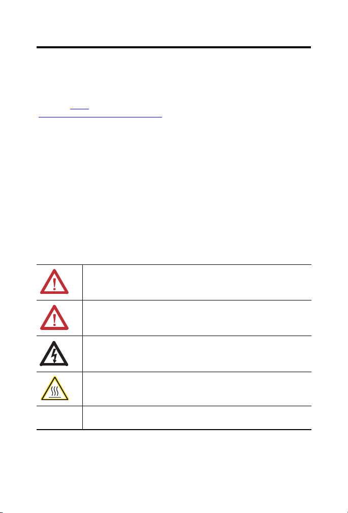
Throughout this manual, when necessary, we use notes to make you aware of safety considerations.
available from your local Rockwell Automation sales office or online at
WARNING: Identifies information about practices or circumstances that can cause an
explosion in a hazardous environment, which may lead to personal injury or death,
property damage, or economic loss.
ATTENTION: Identifies information about practices or circumstances that can lead to
personal injury or death, property damage, or economic loss. Attentions help you
identify a hazard, avoid a hazard and recognize the consequences.
) describes some important differences between
SHOCK HAZARD: Labels may be on or inside the equipment (for example, drive or
motor) to alert people that dangerous voltage may be present.
BURN HAZARD: Labels may be on or inside the equipment (for example, drive or
motor) to alert people that surfaces may reach dangerous temperatures.
IMPORTANT
Identifies information that is critical for successful application and understanding of the
product.
Publication 1794-IN063C-EN-E - February 2014
Page 3

Environment and Enclosure
ATTENTION: This equipment is intended for use in a Pollution Degree 2
industrial environment, in overvoltage Category II applications (as defined in
IEC 60664-1), at altitudes up to 2000 m (6562 ft) without derating.
This equipment is not intended for use in residential environments and may not
provide adequate protection to radio communication services in such
environments.
This equipment is supplied as open-type equipment. It must be mounted within
an enclosure that is suitably designed for those specific environmental
conditions that will be present and appropriately designed to prevent personal
injury resulting from accessibility to live parts. The enclosure must have
suitable flame-retardant properties to prevent or minimize the spread of flame,
complying with a flame spread rating of 5VA or be approved for the application
if nonmetallic. The interior of the enclosure must be accessible only by the use
of a tool. Subsequent sections of this publication may contain additional
information regarding specific enclosure type ratings that are required to
comply with certain product safety certifications.
In addition to this publication, see:
• Industrial Automation Wiring and Grounding Guidelines, Rockwell
Automation publication 1770-4.1
• NEMA Standard 250 and IEC 60529, as applicable, for explanations of the
degrees of protection provided by different types of enclosure.
Prevent Electrostatic Discharge
FLEX I/O 2-Channel Incremental Encoder Module 3
, for additional installation requirements.
ATTENTION: This equipment is sensitive to electrostatic discharge, which can
cause internal damage and affect normal operation. Follow these guidelines
when you handle this equipment:
• Touch a grounded object to discharge potential static.
• Wear an approved grounding wriststrap.
• Do not touch connectors or pins on component boards.
• Do not touch circuit components inside the equipment.
• Use a static-safe workstation, if available.
• Store the equipment in appropriate static-safe packaging when not in use.
Publication 1794-IN063C-EN-E - February 2014
Page 4

4 FLEX I/O 2-Channel Incremental Encoder Module
European Hazardous Location Approval
The following module is European Zone 2 approved: 1794-ID2 Series B.
The following applies when the product bears the Ex Marking
European Zone 2 Certification (The following applies when the product bears the Ex Marking)
This equipment is intended for use in potentially explosive atmospheres as defined by European
Union Directive 94/9/EC. DEMKO certifies that this equipment has been found to comply with the
Essential Health and Safety Requirements relating to the design and construction of Category 3
equipment intended for use in Zone 2 potentially explosive atmospheres, given in Annex II to this
Directive.
Compliance with the Essential Health and Safety Requirements has been assured by
compliance with EN 60079-15:2012 and EN 60079-0:2010.
WARNING: Observe the following additional Zone 2 certification
requirements:
• This equipment is not resistant to sunlight or other sources of UV
radiation.
• This equipment must be installed in an enclosure providing at least IP54
protection when applied in Zone 2 environments.
• This equipment shall be used within its specified ratings defined by
Rockwell Automation.
• Provision shall be made to prevent the rated voltage from being
exceeded by transient disturbances of more than 40% when applied in
Zone 2 environments.
• Secure any external connections that mate to this equipment by using
screws, sliding latches, threaded connectors, or other means provided
with this product.
• Do not disconnect equipment unless power has been removed or the
area is known to be nonhazardous.
Publication 1794-IN063C-EN-E - February 2014
Page 5
FLEX I/O 2-Channel Incremental Encoder Module 5
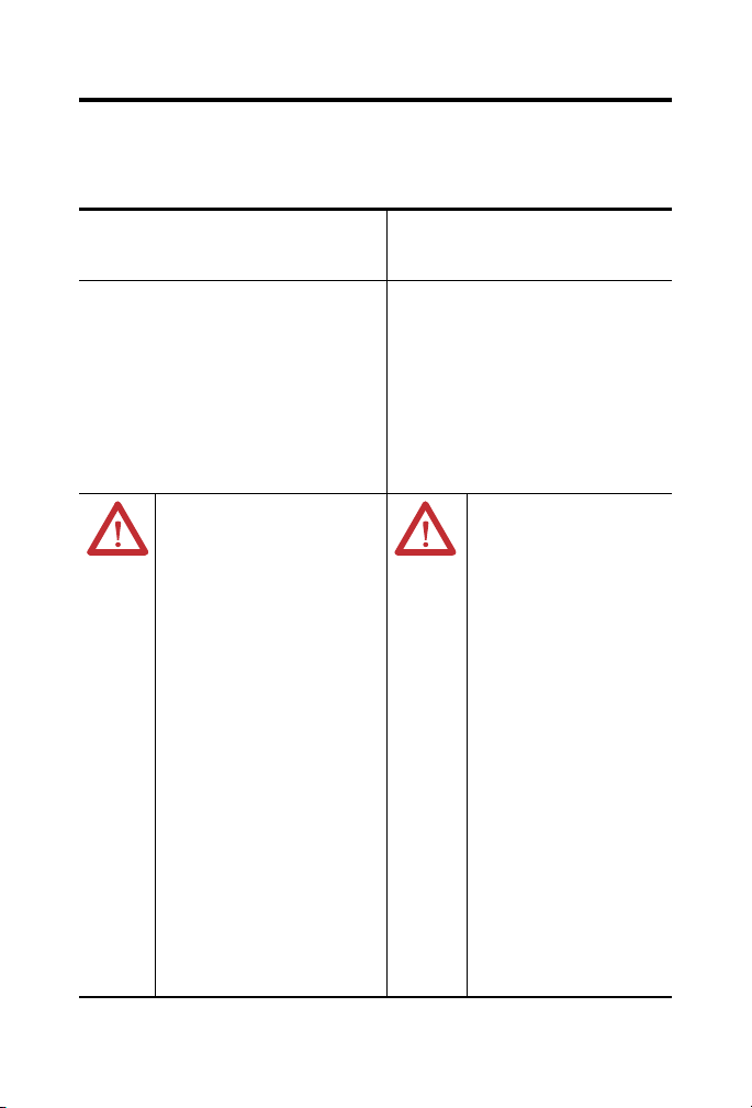
North American Hazardous Location Approval
The following module is North American Hazardous Location approved:
1794-ID2 Series B
The following information applies when
operating this equipment in hazardous
locations:
Products marked “CL I, DIV 2, GP A, B, C, D” are suitable
for use in Class I Division 2 Groups A, B, C, D, Hazardous
Locations and nonhazardous locations only. Each product
is supplied with markings on the rating nameplate
indicating the hazardous location temperature code.
When combining products within a system, the most
adverse temperature code (lowest “T” number) may be
used to help determine the overall temperature code of
the system. Combinations of equipment in your system are
subject to investigation by the local Authority Having
Jurisdiction at the time of installation.
WARNING: EXPLOSION HAZARD
• Do not disconnect equipment
unless power has been
removed or the area is known
to be nonhazardous.
• Do not disconnect connections
to this equipment unless
power has been removed or
the area is known to be
nonhazardous. Secure any
external connections that mate
to this equipment by using
screws, sliding latches,
threaded connectors, or other
means provided with this
product.
• Substitution of components
may impair suitability for Class
I, Division 2.
• If this product contains
batteries, they must only be
changed in an area known to
be nonhazardous.
Informations sur l’utilisation de cet
équipement en environnements
dangereux:
Les produits marqués "CL I, DIV 2, GP A, B, C, D" ne
conviennent qu'à une utilisation en environnements
de Classe I Division 2 Groupes A, B, C, D dangereux et
non dangereux. Chaque produit est livré avec des
marquages sur sa plaque d'identification qui
indiquent le code de température pour les
environnements dangereux. Lorsque plusieurs
produits sont combinés dans un système, le code de
température le plus défavorable (code de température
le plus faible) peut être utilisé pour déterminer le
code de température global du système. Les
combinaisons d'équipements dans le système sont
sujettes à inspection par les autorités locales
qualifiées au moment de l'installation.
WARNING: RISQUE
D’EXPLOSION
• Couper le courant ou
s’assurer que
l’environnement est
classé non dangereux
avant de débrancher
l'équipement.
• Couper le courant ou
s'assurer que
l’environnement est
classé non dangereux
avant de débrancher les
connecteurs. Fixer tous
les connecteurs externes
reliés à cet équipement à
l'aide de vis, loquets
coulissants, connecteurs
filetés ou autres moyens
fournis avec ce produit.
• La substitution de
composants peut rendre
cet équipement inadapté
à une utilisation en
environnement de Classe
I, Division 2.
• S’assurer que
l’environnement est
classé non dangereux
avant de changer les
piles.
Publication 1794-IN063C-EN-E - February 2014
Page 6

6 FLEX I/O 2-Channel Incremental Encoder Module
ATTENTION: Personnel responsible for the application of safety-related
programmable electronic systems (PES) shall be aware of the safety
requirements in the application of the system and shall be trained in using the
system.
ATTENTION: FLEX I/O systems are grounded through the DIN rail to chassis
ground. Use zinc plated yellow-chromate steel DIN rail to assure proper
grounding. The use of other DIN rail materials (for example, aluminum or
plastic) that can corrode, oxidize, or are poor conductors, can result in improper
or intermittent grounding. Secure DIN rail to mounting surface approximately
every 200 mm (7.8 in.) and use end-anchors appropriately.
ATTENTION: Do not remove or replace a Terminal Base unit while power is
applied. Interruption of the backplane can result in unintentional operation or
machine motion.
ATTENTION: For Class I Division 2 applications, use only Class I Division 2
listed or recognized accessories and modules approved for use within the 1794
platform.
ATTENTION: If this equipment is used in a manner not specified by the
manufacturer, the protection provided by the equipment may be impaired.
WARNING: When used in a Class I, Division 2, hazardous location, this
equipment must be mounted in a suitable enclosure with proper wiring
method that complies with the governing electrical codes.
WARNING: If you connect or disconnect wiring while the field-side power is
on, an electrical arc can occur. This could cause an explosion in hazardous
location installations. Be sure that power is removed or the area is
nonhazardous before proceeding.
Publication 1794-IN063C-EN-E - February 2014
Page 7

FLEX I/O 2-Channel Incremental Encoder Module 7
44341
3
4
7
1
2
6
5
Install the Module
Read this for information about how to install the module, which mounts on a 1794-TB3
or 1794-TB3S terminal base.
Module Description
Description Description
1 Latching mechanism 5 Alignment bar
2 Keyswitch 6 Module
3 Terminal base 7 FlexBus connector
4Groove
ATTENTION: During mounting of all devices, be sure that all debris (such as
metal chips or wire strands) is kept from falling into the module. Debris that
falls into the module could cause damage on powerup.
To install the module on a 1794 terminal base, refer to the figure and complete the
following.
1. Rotate the keyswitch (2) on the terminal base (3) clockwise to position 3 as
required for this type of module.
2. Make sure the flexbus connector (7) is pushed all the way to the left to connect
with the neighboring terminal base or adapter.
ATTENTION: You cannot install the module unless the connector is fully
extended.
Publication 1794-IN063C-EN-E - February 2014
Page 8

8 FLEX I/O 2-Channel Incremental Encoder Module
3. Make sure the pins on the bottom of the module are straight so they align
properly with the connector in the terminal base.
WARNING: If you remove or insert the module while the backplane power is
on, an electrical arc can occur. This could cause an explosion in hazardous
location installations. Be sure that power is removed or the area is
nonhazardous before proceeding.
4. Position the module (6) with its alignment bar (5) aligned with the groove (4) on
the terminal base.
5. Press firmly and evenly to seat the module in the terminal base unit, noting that
the module is seated when the latching mechanism (1) is locked into the module.
Remove debris wrapper before applying power to the module.
Wire the Module
1794-TB3 and 1794-TB3S Terminal Base Wiring
WARNING: If you connect or disconnect wiring while the field-side power is
on, an electrical arc can occur. This could cause an explosion in hazardous
location installations. Be sure that power is removed or the area is
nonhazardous before proceeding.
To connect wiring for 1794-TB3 and 1794-TB3S bases, refer to the tables and figure and
complete the following.
1. Connect individual input wiring (A+, A-, B+, B-, Z+, Z-, G+, G-) for each
channel to numbered terminals on the 0…15 row (A) as indicated in the table
below.
2. If applicable, connect the encoder commons to any terminal on the 16…33 row
(B) for each input as indicated.
ATTENTION: To reduce susceptibility to noise, power analog modules and
digital modules from separate power supplies. Do not exceed a length of 3 m
(9.8 ft) for DC power cabling.
Publication 1794-IN063C-EN-E - February 2014
Page 9

FLEX I/O 2-Channel Incremental Encoder Module 9
17 18 19 20 21 22 23 24 25 26 27 28 29 30 31 32 33
0 1 2 3 4 5 6 7 8 9 10 11 12 13 14 15
16
35 36 37 38 39 40 41 42 43 44 45 46 47 48 49 50 51
34
Inputs
Commons
(1794-TB3 shown)
-V (Supply Common) = Terminals B-16 and B-33
+V (Supply +Voltage) = Terminals C-34 and C-51
-V
Voltage
In +V
Voltage
Out +V
Voltage
A
B
C
Common
-V
Common
Use B-33 and C-51 for daisy-chaining to next terminal base unit.
3. Connect any signal wiring shields to functional ground as near as possible to the
module.
4. When powering the encoder from the 1794-ID2 module, connect the encoder
power lead to any terminal on the 34…51 row (C).
5. Connect +V DC power to terminal 34 on the 34…51 row (C).
6. Connec DC return to terminal 16 on the 16…33 (B).
7. If daischaining power to the next terminal base, connect a jumper from terminal
51 (+V DC) on this base unit to terminal 34 on the next base unit.
8. If continuing DC common to the next base unit, connect a jumper from terminal
33 (common) on this base unit to terminal 16 on the next base unit.
Publication 1794-IN063C-EN-E - February 2014
Page 10

10 FLEX I/O 2-Channel Incremental Encoder Module
16
0
1
2
3
4
5
6789101112
13
14
15
51
33
34
+V
COM
+V
COM
B
C
Even Numbered I/O Terminals 0…14
Odd Numbered I/O Terminals 1…15
+V = Terminals C-34 and C-51
COM (-V) = Terminals B-16 and B-33
1794-TBN Terminal Base Wiring
Wiring Connections for 1794-ID2
Signal
Name
1794-TB3, 1794-TB3S 1794-TBN
Signal 0V DC COM 12/24V DC Signal
Channel 0
A+ A-0 B-17 C-35 B-0
A- A-1 B-18 C-36 C-1
B+ A-2 B-19 C-37 B-2
B- A-3 B-20 C-38 C-3
Z+ A-4 B-21 C-39 B-4
Z- A-5 B-22 C-40 C-5
G+ A-6 B-23 C-41 B-6
G- A-7 B-24 C-42 C-7
Channel 1
A+ A-8 B-25 C-43 B-8
A- A-9 B-26 C-44 C-9
B+ A-10 B-27 C-45 B-10
B- A-11 B-28 C-46 C-11
Z+ A-12 B-29 C-47 B-12
Z- A-13 B-30 C-48 C-13
G+ A-14 B31- C-49 B-14
G- A-15 B-32 C-50 C-15
0V DC
COM
Terminals 16…33 (1794-TB3, 1794-TB3S) Terminals 16 and 33
12/24V DC Terminals 34…51 (1794-TB3, 1794-TB3S) Terminals 34 and 51
1 Auxiliary terminal blocks are required when using these terminal base units.
Publication 1794-IN063C-EN-E - February 2014
1
Page 11

FLEX I/O 2-Channel Incremental Encoder Module 11
_
+
G
Z
B
A
_
+
_
+
_
+
17 18 19 20
21
22 23 24 25
33
012
345
6
78
16
35 36
37 38
39 40 41 42
15
51
34
0V DC
12/24V DC
External
power supply
12/24V DC
Pulse Counter Channel 0
Signal inputs
Signal for
counter gate
Signal for counter
calibration/preset
Signal for
up/down counting
+
G
Z
B
A
+
_
+
+
17 18 19
20 212223 24
25
33
0
1
2
34
5
678
16
353637
38
39 40
41 42
15
51
34
0V DC
12/24V DC
External
power supply
12/24V DC
Pulse Counter Channel 0
Signal inputs
_
_
_
_
Example of Incremental Encoder Wiring
Example of pulse transmitter with 1 pulse train. For connection of channel 1, refer to
connection diagram. To reduce noise, connect negative input to 0V DC terminal.
Note: Dotted lines indicate signals not always used.
Example of incremental encoder with 2 pulse trains, with or without reference, and/or gate
function. For connection of channel 1, refer to connection diagram.
Note: Dotted lines indicate signals not always used.
Publication 1794-IN063C-EN-E - February 2014
Page 12

12 FLEX I/O 2-Channel Incremental Encoder Module
Input (read) Image for 1794-ID2
Dec. 15 14 131211109 8 76543210
Oct. 17 16 15141312111076543210
0CT
1 Channel 0 - Stored counter value of channel 0
2 Channel 1 - Stored counter value of channel 1
3 Channel 0 - Current counter value
4 Channel 1 - Current counter value
5 Channel 0 - Counter word readback
6 Channel 1 - Counter word readback
7 Revision read - software version code
Where A0 = Status of input A, channel 0 - bit = 1 when input is on
B0 = Status of input B, channel 0 - bit = 1 when input is on
Z0 = Status of input Z, channel 0 - bit = 1 when input is on
G0 = Status of input G, channel 0 - bit = 1 when input is on
A1= Status of input A, channel 1 - bit = 1 when input is on
B1 = Status of input B, channel 1 - bit = 1 when input is on
Z1 = Status of input Z, channel 1 - bit = 1 when input is on
G1 = Status of input G, channel 1 - bit = 1 when input is on
C0 = Cal 0 - when bit is set, counter 0 has been calibrated (reset by CalReset)
C1 = Cal 1 - when bit is set, counter 1 has been calibrated (reset by CalReset)
S0 = Stored 0 - when bit is set, counter 0 value has been saved in Store 0 (reset by
StoreReset)
S1 = Stored 1 - when bit is set, counter 1 value has been saved in Store 0 (reset by
StoreReset)
Once a store has occurs, L0 and L1 are on until cleared by StoreReset (counter word bit 14)
PR0 = Preset 0 reached - when bit is set, counter 0 has reached value of preset (reset by
PresetReset)
PR1 = Preset 1 reached - when bit is set, counter 1 has reached value of preset (reset by
PresetReset)
CT DIR 0 = Increase/Decrease counter value for counter 0: set to 0 at startup. 0 = last pulse
decreased
counter value; 1 = last pulse increased counter value
CT DIR 1 = Increase/Decrease counter value for counter 1: set to 0 at startup. 0 = last pulse
decreased
counter value; 1 = last pulse increased counter value
DIR
1
CT
PR1PR0S1 S0 C1 C0 G1Z1B1A1G0Z0B0A
DIR
0
0
Publication 1794-IN063C-EN-E - February 2014
Page 13

FLEX I/O 2-Channel Incremental Encoder Module 13
Output/Configuration Image for 1794-ID2
Dec. 15 14 13 12 11 10 9 8 7 6 5 4 3 2 1 0
Oct. 17 16 15 14 13 12 11 10 7 6 5 4 3 2 1 0
0 Control Word 0 - Channel 0 - Sets the function of counter 0
1 Control Word 1 - Channel 1 - Sets the function of counter 1
2 Channel 0 Preset - Value to load or compare with counter 0
3 Channel 1 Preset - Value to load or compare with counter 1
4 Control Word 2 - Filter Function Control Word - Enables filter, and sets filter constant
5…6 Reserved
Description of Control Words 0 and 1
Bit Description
00…02 02 01 00 Mode Selection Bits
0 0 0 Counting on positive (rising) edge of input signal A. (Up/dwn
0 0 1 Quadrature encoder X1
0 1 0 Quadrature encoder X2
0 1 1 Quadrature encoder X4
1 0 0 Counting up on positive edge of input signal A, and counting
1 0 1 No count function
110
111
03 Preset (Reset) bit - A positive edge on this bit moves the value in Preset X to
Counter X, independent of Preset Enable. Note: To use Preset as a Reset, use a count
value of 0000 in the Preset Value word.
04 Enable Z Preset (Reset) bit - When this bit is set (1), a positive edge on Z preloads
Counter X = Preset X, independent of Cal Enable. Note: If Z is configured to do Store
and Preset (Reset), the Store will occur first.
05 Count Enable bit - When this bit is set (1), the pulse counter is enabled.
Calibration Control Bits 06-08
06 Enable bit - When this bit is set (1), the pulse counter can be calibrated.
07 Direction bit - When this bit is set (1), calibration is performed in a negative
direction; when reset (0), calibration is performed in a positive direction.
08 Reset bit - Calibration is acknowledged and a new calibration is enabled on a
positive edge on this bit.
counting determined by B.)
down on positive edge of input signal B.
Publication 1794-IN063C-EN-E - February 2014
Page 14

14 FLEX I/O 2-Channel Incremental Encoder Module
Description of Control Words 0 and 1
Bit Description
09…10 10 09 Gate Control Bits
0 0 No gate function on input G
0 1 Counting only if G is high (active)
1 0 Counting only if G is low (inactive)
1 1 The counter can be calibrated when G is high (active)
11…12 12 11 Store Control Bits - These bits will trigger a Store only if the
0 0 Save counter value on positive edge of Z (if S0 or S1 = 0)
0 1 Save counter value on positive edge of G (if S0 or S1 = 0)
1 0 Save counter value on negative edge of G (if S0 or S1 = 0)
1 1 Save the counter value on the positive edge and negative edge of G
13 Rollover bit - When set (1), the counter counts up to the preset and then restarts at 0.
If this bit is reset (0) (not rollover), the rollover preset value is FFFF hex = 65535
decimal
14 Store Reset bit - A positive edge on this bit resets the channel Store status bit (S0 or
S1).
15 Preset Reset bit - A positive edge on this bit resets the Preset Reached (PR0 or PR1).
channel Store status bit (S0 or S1) are cleared (0).
(if S0 or S1 = 0)
Decription of Control Word 2
Bit Description
00 Filter A0 Enable bit - When this bit is set (1), and counter 0 is in mode 000 (Pulse
counting), signal A0 is filtered by a digital low pass filter with selectable constant.
01 Filter A1 Enable bit - When this bit is set (1), and counter 1 is in mode 000 (Pulse
counting), signal A1 is filtered by a digital low pass filter with selectable constant.
02…07 Reserved - set to 0
08…09 09 08 Filter Constant Bits - This constant is common to both counters
0 0 73.5 kHz or min 0.007 ms pulsewidth
0 1 37.8 kHz or min 0.013 ms pulsewidth
1 0 12.8 kHz or min 0.04 ms pulsewidth
1 1 1.2 kHz or min 0.4 ms pulsewidth
10…15 Reserved - set to 0
Publication 1794-IN063C-EN-E - February 2014
Page 15

FLEX I/O 2-Channel Incremental Encoder Module 15
Specifications
General Specification
Attribute Value
Number of inputs 2
Number of inputs per counter 4 (A, B, Z, and G)
Module Location 1794-TB3, 1794-TB3S, 1794-TBN
Terminal base screw torque 1794-TB3, 1794-TB3S – 0.8 Nm (7 lb-in.)
Dimensions, HxWxD
(with module installed)
Input pulse width, min Each signal condition must be stable for at least 2 µs to be
Counting frequency, max 100 kHz
Input range
Input ON
Input OFF
Input current, typical 3 mA @ 6V DC
Isolation voltage Tested @ 500V DC for 1 s
Flexbus current 5 mA @ 5V DC
Power supply (external) 12…24V DC (+10%)
Current consumption from
external power supply
Power dissipation, max 5 W @ 26.4V DC
Thermal dissipation, max 17.1 BTU/hr @ 26.4V DC
Indicators (field side indication,
customer device driven)
Keyswitch position 1
1794-TBN – 1.0 Nm (9 lb-in.)
45.7 x 94.0 x 53.3 mm (1.8 x 3.7 x 2.1 in.)
recognized
26.4V DC (24V DC +10%) max
6V DC min
3V DC max
-26.4V DC min
9 mA @ 12V DC
15 mA @ 24V DC
150 mA @ 12V DC
75 mA @ 24V DC
1 green/red power/status indicator
12 yellow status indicators
Publication 1794-IN063C-EN-E - February 2014
Page 16

16 FLEX I/O 2-Channel Incremental Encoder Module
Environmental Specifications
Attribute Value
Temperature, operating IEC 60068-2-1 (Test Ad, Operating Cold),
Temperature, nonoperating IEC 60068-2-1 (Test Ab, Unpackaged Nonoperating Cold),
Relative humidity IEC 60068-2-30 (Test Db, Unpackaged Damp Heat)
Vibration IEC 60068-2-6 (Test Fc, Operating):
Shock, operating IEC 60068-2-27 (Test Ea, Unpackaged Shock): 30 g
Shock, nonoperating IEC 60068-2-27 (Test Ea, Unpackaged Shock): 50 g
Emissions CISPR 11 (IEC 61000-6-4): Class A
ESD immunity IEC 61000-4-2:
Radiated RF immunity IEC 61000-4-3:
EFT/B immunity IEC 61000-4-4:
Surge transient immunity IEC 61000-4-5:
Conducted RF immunity IEC 61000-4-6:
IEC 60068-2-2 (Test Bd, Operating Dry Heat),
IEC 60068-2-14 (Test Nb, Operating Thermal Shock):
0…55 °C (32…131 °F)
Note: Do not connect maximum input voltage
simultaneously to all inputs if the module ambient
temperature is expected to exceed 40 °C.
IEC 60068-2-2 (Test Bb, Unpackaged Nonoperating Dry Heat),
IEC 60068-2-14 (Test Na, Unpackaged Nonoperating Thermal
Shock):
-40…85 °C (-40…185 °F)
5…95% noncondensing
5 g @ 10…500 Hz
4 kV contact discharges
8 kV air discharges
10 V/m with 1 kHz sine-wave 80%AM from
30 MHz…1000 MHz
±2 kV @ 5 kHz on signal ports
±2 kV line-earth(CM) on shielded ports
10V rms with 1 kHz sine-wave 80% AM from
150 kHz…80 MHz
Publication 1794-IN063C-EN-E - February 2014
Page 17

FLEX I/O 2-Channel Incremental Encoder Module 17
Certifications
Certification (when
product is marked)
(1)
c-UL-us UL Listed Industrial Control Equipment, certified for US and
CE European Union 2004/108/EC EMC Directive, compliant with:
C-Tick Australian Radiocommunications Act, compliant with:
(1)
See the product certifications link at http://www.rockwellautomation.com/products/certification/ for Declarations of
Conformity, Certificates, and other certification details.
Valu e
Canada.
UL Listed for Class I, Division 2 Group A,B,C,D Hazardous
Locations, certified for U.S. and Canada.
EN 61326-1; Meas./Control/Lab., Industrial Requirements
EN 61000-6-2; Industrial Immunity
EN 61000-6-4; Industrial Emissions
EN 61131-2; Programmable Controllers (Clause 8, Zone A
& B)
AS/NZS CISPR 11; Industrial Emissions
Publication 1794-IN063C-EN-E - February 2014
Page 18

18 FLEX I/O 2-Channel Incremental Encoder Module
Notes:
Publication 1794-IN063C-EN-E - February 2014
Page 19

Notes:
FLEX I/O 2-Channel Incremental Encoder Module 19
Publication 1794-IN063C-EN-E - February 2014
Page 20

Rockwell Automation Support
Rockwell Automation provides technical information on the Web to assist you in using its products. At
http://www.rockwellautomation.com/support/
technical and application notes, sample code and links to software service packs, and a MySupport feature
that you can customize to make the best use of these tools.
For an additional level of technical phone support for installation, configuration and troubleshooting, we
offer TechConnect support programs. For more information, contact your local distributor or Rockwell
Automation representative, or visit http://www.rockwellautomation.com/support/
, you can find technical manuals, a knowledge base of FAQs,
.
Installation Assistance
If you experience a problem within the first 24 hours of installation, please review the information that's
contained in this manual. You can also contact a special Customer Support number for initial help in getting
your product up and running.
United States or Canada 1.440.646.3434
Outside United States or
Canada
Use the Worldwide Locator
http://www.rockwellautomation.com/support/americas/phone_en.html
contact your local Rockwell Automation representative.
at
, or
New Product Satisfaction Return
Rockwell Automation tests all of its products to ensure that they are fully operational when shipped from
the manufacturing facility. However, if your product is not functioning and needs to be returned, follow
these procedures.
United States Contact your distributor. You must provide a Customer Support case number
Outside United States Please contact your local Rockwell Automation representative for the return
(call the phone number above to obtain one) to your distributor to complete
the return process.
procedure.
Documentation Feedback
Your comments will help us serve your documentation needs better. If you have any suggestions on how to
improve this document, complete this form, publication RA-DU002
http://www.rockwellautomation.com/literature/
.
, available at
Allen-Bradley, Rockwell Automation, ArmorBlock, and TechConnect are trademarks of Rockwell Automation, Inc.
Trademarks not belonging to Rockwell Automation are property of their respective companies.
Publication 1794-IN063C-EN-E - February 2014
Supersedes 1794-IN063B-EN-P February 2001 Copyright © 2014 Rockwell Automation, Inc. All rights reserved.
 Loading...