

Page 1
Installation Instructions
FLEX I/O Digital Input/Output Modules
Cat. No. 1794-IB10XOB6, 1794-IB16XOB16P
Important User Information
Solid state equipment has operational characteristics differing from those of
electromechanical equipment. Safety Guidelines for the Application, Installation and
Maintenance of Solid State Controls (Publication SGI-1.1 available from your local Rockwell
Automation sales office or online at http://www.ab.com/manuals/gi) describes some
important differences between solid state equipment and hard-wired electromechanical
devices. Because of this difference, and also because of the wide variety of uses for solid
state equipment, all persons responsible for applying this equipment must satisfy themselves
that each intended application of this equipment is acceptable.
In no event will Rockwell Automation, Inc. be responsible or liable for indirect or
consequential damages resulting from the use or application of this equipment.
The examples and diagrams in this manual are included solely for illustrative purposes.
Because of the many variables and requirements associated with any particular installation,
Rockwell Automation, Inc. cannot assume responsibility or liability for actual use based on
the examples and diagrams.
No patent liability is assumed by Rockwell Automation, Inc. with respect to use of
information, circuits, equipment, or software described in this manual.
Reproduction of the contents of this manual, in whole or in part, without written permission
of Rockwell Automation, Inc. is prohibited.
Throughout this manual we use notes to make you aware of safety considerations.
WARNING
IMPORTANT
ATTENTION
ATTENTION
Identifies information about practices or circumstances that can cause
an explosion in a hazardous environment, which may lead to personal
injury or death, property damage, or economic loss.
Identifies information that is critical for successful application and
understanding of the product.
Identifies information about practices or circumstances that can lead to
personal injury or death, property damage, or economic loss. Attentions
help you:
• identify a hazard
• avoid a hazard
• recognize the consequence
Environment and Enclosure
This equipment is intended for use in a Pollution Degree 2
industrial environment, in overvoltage Category II applications
(as defined in IEC publication 60664-1), at altitudes up to 2000
meters without derating.
This equipment is considered Group 1, Class A industrial
equipment according to IEC/CISPR Publication 11. Without
appropriate precautions, there may be potential difficulties
ensuring electromagnetic compatibility in other environments
due to conducted as well as radiated disturbance.
This equipment is supplied as "open type" equipment. It must
be mounted within an enclosure that is suitably designed for
those specific environmental conditions that will be present and
appropriately designed to prevent personal injury resulting
from accessibility to live parts. The interior of the enclosure
must be accessible only by the use of a tool. Subsequent
sections of this publication may contain additional information
regarding specific enclosure type ratings that are required to
comply with certain product safety certifications.
See NEMA Standards publication 250 and IEC publication
60529, as applicable, for explanations of the degrees of
protection provided by different types of enclosure. Also, see
the appropriate sections in this publication, as well as the
Allen-Bradley publication 1770-4.1 ("Industrial Automation
Wiring and Grounding Guidelines"), for additional installation
requirements pertaining to this equipment.
WARNING
ATTENTION
WARNING
ATTENTION
When you insert or remove the module while backplane
power is on, an electrical arc can occur. This could cause an
explosion in hazardous location installations. Be sure that
power is removed or the area is nonhazardous before
proceeding.
FLEX I/O is grounded through the DIN rail to chassis
ground. Use zinc plated yellow-chromate steel DIN rail to
assure proper grounding. The use of other DIN rail
materials (e.g. aluminum, plastic, etc.) that can corrode,
oxidize, or are poor conductors, can result in improper or
intermittent grounding.
If you connect or disconnect wiring while the field side
power is on, an electrical arc can occur. This could cause an
explosion in hazardous location installations. Be sure that
power is removed or the area is nonhazardous before
proceeding.
Preventing Electrostatic Discharge
This equipment is sensitive to electrostatic discharge, which
can cause internal damage and affect normal operation.
Follow these guidelines when you handle this equipment:
• Touch a grounded object to discharge potential static.
• Wear an approved grounding wriststrap.
• Do not touch connectors or pins on component
boards.
• Do not touch circuit components inside the
equipment.
• If available, use a static-safe workstation.
European Hazardous Location Approval
The following module is European Zone 2 approved: 1794-IB10XOB6.
European Zone 2 Certification (The following applies when the
product bears the EEx Marking)
This equipment is intended for use in potentially explosive atmospheres as
defined by European Union Directive 94/9/EC.
The LCIE (Laboratoire Central des Industries Electriques) certifies that this
equipment has been found to comply with the Essential Health and Safety
Requirements relating to the design and construction of Category 3
equipment intended for use in potentially explosive atmospheres, given in
Annex II to this Directive. The examination and test results are recorded in
confidential report No. 28 682 010.
Compliance with the Essential Health and Safety Requirements has been
assured by compliance with EN 50021.
IMPORTANT
Observe the following additional Zone 2 certification
requirements.
• This equipment is not resistant to sunlight or other
sources of UV radiation.
• The secondary of a current transformer shall not be
open-circuited when applied in Class I, Zone 2
environments.
• Equipment of lesser Enclosure Type Rating must be
installed in an enclosure providing at least IP54
protection when applied in Class I, Zone 2
environments.
• This equipment shall be used within its specified
ratings defined by Allen-Bradley.
• Provision shall be made to prevent the rated voltage
from being exceeded by transient disturbances of
more than 40% when applied in Class I, Zone 2
environments
Publication 1794-IN083B-EN-P - November 2004
Page 2
2
North American Hazardous Location Approval
The following modules are North Am erican Hazardous Location approv ed:
1794-IB10XOB6 an d 1794-IB16XOB16P.
The following information applies when
operating this equipment in hazardous
locations:
Products marked “ CL I, DIV 2, GP A, B, C, D” are
suitable for use in C lass I Division 2 Groups A, B, C,
D, Hazardous Locations and nonhazardous locations
only. Each product is supp lied with markings on the
rating namepla te indicating the ha zardous location
temperature co de. When combining produ cts within
a system, the most adverse temperature code
(lowest “T” number ) may be used to help deter mine
the overall temperatur e code of the system.
Combinations of equipment in your sys tem are
subject to investiga tion by the local Authority
Having Jurisdic tion at the time of in stallation.
WARNING
EXPLOSION HAZARD
• Do not disc onnect
equipment unles s power
has been removed or the
area is known to be
nonhazardous.
• Do not disc onnect
connections t o this
equipment unles s power
has been removed or the
area is known to be
nonhazardous. Secure any
external conne ctions that
mate to this equipment by
using screws, slidin g
latches, threaded
connectors, or other means
provided with this product.
• Substitu tion of
components ma y impair
suitability for Clas s I,
Division 2.
• If this product contains
batteries, they must only be
changed in an area known
to be nonhazardous.
Informations sur l’utilisation de cet équipement
en environnements dangereux :
Les produits ma rqués "CL I, DIV 2, GP A , B, C, D" ne
conviennent qu’à u ne utilisation en environne ments
de Classe I Divisio n 2 Groupes A, B, C, D dan gereux et
non dangereux. Chaque produit est livré avec des
marquages su r sa plaque d’identific ation qui
indiquent le code de te mpérature pour les
environnement s dangereux. Lorsque plu sieurs
produits sont combinés dans un système, le code de
température le plus défavorable (code de tempé rature
le plus faible) pe ut être utilisé pour détermi ner le
code de température global du système. Les
combinaisons d’équipement s dans le système sont
sujettes à inspection pa r les autorités locales
qualifiées au mom ent de l’installation.
AVERTISSEMENT
RISQUE D’EXPLOSION
• Couper le courant ou
s’assurer que l’en vironnement
est classé non dang ereux avant
de débrancher l'équipement.
• Couper le courant ou
s'assurer que l’en vironnement
est classé non dang ereux avant
de débrancher les connecteurs.
Fixer tous les connecteurs
externes reli és à cet
équipement à l'aide de vis,
loquets couliss ants,
connecteurs filetés ou autres
moyens fournis a vec ce produit.
• La substitution de
composants p eut rendre cet
équipement in adapté à une
utilisation en envir onnement de
Classe I, Division 2.
• S’assurer que
l’environneme nt est classé no n
dangereux avan t de changer
les piles.
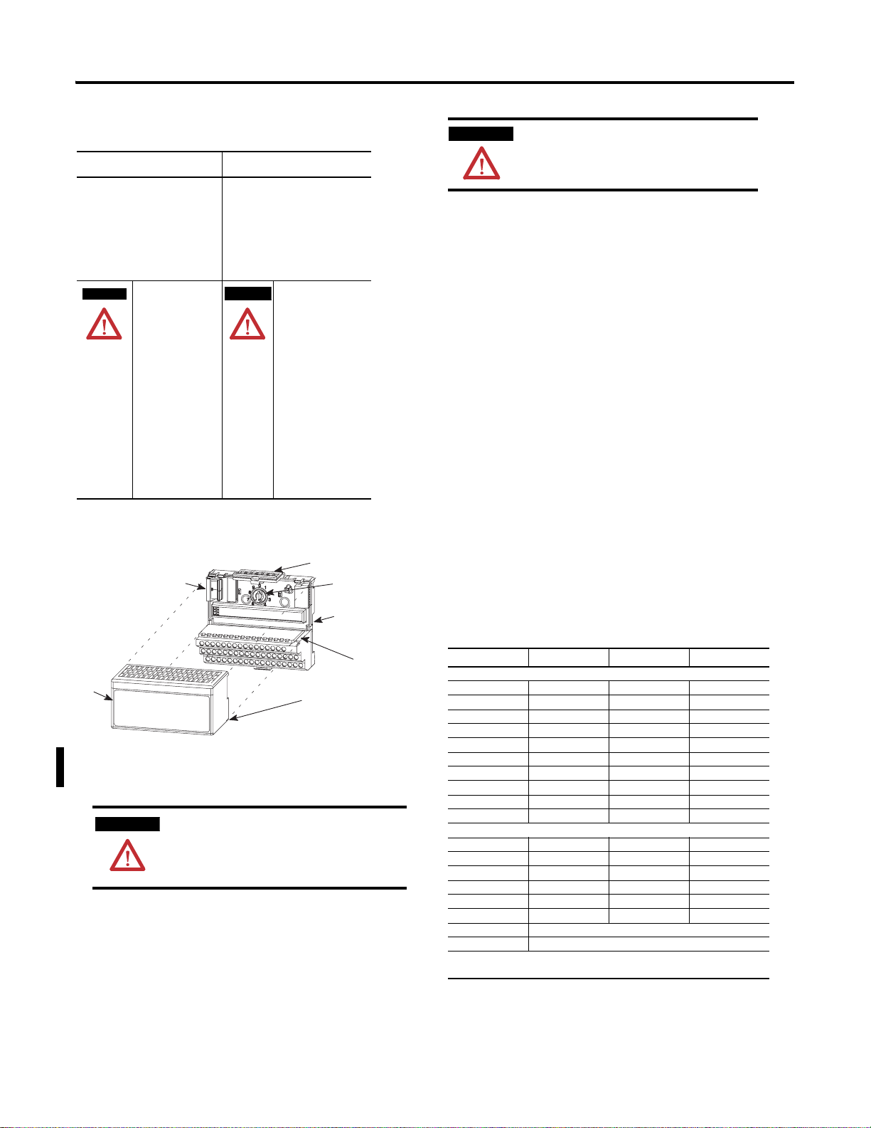
Installing Your Digital Input/Output Module
7
3
4
The 1794-IB10XOB6 module mounts on a 1794-TB3 or -TB3S terminal base.
The 1794-IB16XOB16P module mounts on a 1794-TB32 or -TB32S terminal
base.
ATTENTION
During mounting of all devices, be sure that all
debris (metal chips, wire strands, etc.) is kept
from falling into the module. Debris that falls
into the module could cause damage on
power up.
1. Rotate the keyswitch (1) on the terminal base (2) clockwise to position
2 as required for this type of module.
2. Make certain the flexbus connector (3) is pushed all the way to the left
to connect with the neighboring terminal base/adapter. You cannot
install the module unless the connector is fully extended.
3. Make sure the pins on the bottom of the module are straight so they
will align properly with the connector in the terminal base.
1
2
6
5
WARNING
If you remove or insert the module while the
backplane power is on, an electrical arc can occur.
This could cause an explosion in hazardous location
installations. Be sure that power is removed or the
area is nonhazardous before proceeding..
4. Position the module (4) with its alignment bar (5) aligned with the
groove (6) on the terminal base.
5. Press firmly and evenly to seat the module in the terminal base unit.
The module is seated when the latching mechanism (7) is locked into
the module.
Connecting Wiring for the 1794-IB10XOB6
1. Connect individual input and output wiring to numbered terminals on
the 0-15 row (A) as indicated in the table below.
2. Connect the associated +V dc power lead of the input device to the
corresponding terminal on the 34-51 row (C) for each input as
indicated in the table below. (The +V power terminals of row (C) are
internally connected together.)
3. Connect the associated input device common (3-wire devices only)
and output device common to the corresponding terminals on the
16-33 row. (B) for each input and output as indicated in the table
below. (Commons are internally connected together.)
4. Connect +V dc power to terminal 34 on the 34-51 row (C).
5. Connect dc common to terminal 16 on the 16-33 row (B).
6. If daisychaining power to the next terminal base, connect a jumper
from terminal 51 (+V dc) on this base unit to terminal 34 on the next
base unit.
7. If continuing dc common to the next base unit, connect a jumper
from terminal 33 (common) on this base unit to terminal 16 on the
next base unit.
Wiring Connections for the 1794-IB10XOB6
1
Input
Sink Input
Input 0 A-0 B-17 C-35
Input 1 A-1 B-18 C-36
Input 2 A-2 B-19 C-37
Input 3 A-3 B-20 C-38
Input 4 A-4 B-21 C-39
Input 5 A-5 B-22 C-40
Input 6 A-6 B-23 C-41
Input 7 A-7 B-24 C-42
Input 8 A-8 B-25 C-43
Input 9 A-9 B-26 C-44
Source Output
Output 0 A-10 B-27
Output 1 A-11 B-28
Output 2 A-12 B-29
Output 3 A-13 B-30
Output 4 A-14 B-31
Output 5 A-15 B-32
+V dc C-34 thru C-51 (internally connected together)
Common B-16 thru B-33 (internally connected together)
1
Two wire input devices use signal and supply terminals. Three wire devices use
signal, return and supply terminals.
Signal Return Supply
Publication 1794-IN083B-EN-P - November 2004
Page 3

3
Inputs
n)
Inputs
1794-TB3 and -TB3S Terminal Base Wiring for the
1794-IB10XOB6
0 1 2 3 4 5 6 7 8 9 10 11 12 13 14 15
17 18 19 20 21 22 23 24 25 26 27 28 29 30 31 32 33
16
-V
Common
35 36 37 38 39 40 41 42 43 44 45 46 47 48 49 50 51
34
Voltage
In +V
-V (Supply Common) = Terminals B-16 and B-33
+V (Supply +Voltage In) = Terminals C-34 and C-51
(Use B-33 and C-51 for daisy-chaining to next terminal base unit)
Commons
Voltage
Outputs
A
B
-V
Common
Voltage
Out +V
(1794-TB3 show
C
2 and 3-Wire Input Wiring for 1794-IB10XOB6
0-15
16-33
34-51
B
C
= Sink Input
A
= Common
B
= +V dc
C
??
??
2-Wire Device
(Sourcing Output)
3-Wire Device
(Sourcing Output)
?
A
Connecting Wiring for the 1794-IB16XOB16P
1. Connect individual input wiring (IN0 to IN15) to numbered terminals
on the 0-15 row (A) as indicated in the table below.
2. Connect the associated power to the +V1 terminal (35, 37, 39 or 41)
on the 34-51 row (C) as indicated in the table below.
3. Connect the associated common (-V1) for IN0 to IN15 to COM1
(terminal 36, 38, 40 or 42) on the 34-51 row (C).
4. Connect individual output wiring (OUT0 to OUT15) to terminals 17
thru 32 on the 16-33 row (B) as indicated in the table below. (Note:
Do not connect to terminals 16 or 33.)
5. Connect the associated power to the +V2 terminal (43, 45, 47 or 49)
on the 34-51 row (C) as indicated in the table below.
6. Connect the associated common (-V2) for OUT0 to OUT15 to
COM2 (terminal 44, 46, 48 or 50) on the 34-51 row (C).
7. If continuing input wiring to the next terminal base unit, connect a
jumper from terminal 41(+V1) to the power terminal on the next base
unit; connect a jumper from terminal 42 (COM1) to the common
terminal on the next base unit.
8. If continuing output wiring to the next terminal base unit, connect a
jumper from terminal 49 (+V2) to the power terminal on the next
base unit; connect a jumper from terminal 50 (COM2) to the common
terminal on the next base unit.
Wiring for 1794-IB16XOB16P (use with 1794-TB32 or -TB32S
terminal base unit)
Input
Input 0 A-0 V1 Return
Input 1 A-1
Input 2 A-2
Signal Return
connected to
terminals 36, 38,
40 and 42
Input 3 A-3
Input 4 A-4
Input 5 A-5
Input 6 A-6
Input 7 A-7
Input 8 A-8
Input 9 A-9
Input 10 A-10
Input 11 A-11
Input 12 A-12
Input 13 A-13
Input 14 A-14
Input 15 A-15
Output 0 B-17 V2 Return
Output 1 B-18
Output 2 B-19
connected to
terminals 44, 46,
48 and 50
Output 3 B-20
Output 4 B-21
Output 5 B-22
Output 6 B-23
Output 7 B-24
Output 8 B-25
Output 9 B-26
Output 10 B-27
Output 11 B-28
Output 12 B-29
Output 13 B-30
Output 14 B-31
Output 15 B-32
+V1 dc power Power terminals 35, 37, 39 and 41
Com1 dc Return Common terminals 36, 38, 40 and 42
+V2 dc power Power terminals 43, 45, 47 and 49
Com2 dc Return Common terminals 44, 46, 48 and 50
1
2-wire input devices use signal and supply terminals; 3-wire devices use signal, return
and supply terminals
1
Supply
+V1 connected to
terminals 35, 37,
39 and 41
+V2 connected to
terminals 43, 45,
47 and 49
1794-TB32 Terminal Base Wiring for the 1794-I B 16XOB16P
0 1 2 3 4 5 6 7 8 9 10 11 12 13 14 15
IN0 IN 1 IN2 IN3 IN4 IN5 IN6 IN7 IN8 IN9 IN10 IN11 IN12 IN13 IN14 IN15
17 18 19 20 21 22 23 24 25 26 27 28 29 30 31 32 33
NC
OUT0 OUT1 OUT2 OUT3 OUT4 OUT5 OUT6 OUT7 OUT8 OUT9 OUT10 OUT11 OUT12 OUT13 OUT14 OUT15
35 36 37 38 39 40 41 42 43 44 45 46 47 48 49 50 51
34
NC
+V1 COM1 +V1 COM1 +V1 COM1 +V1 COM1 +V2 COM2 +V2 COM2 +V2 COM2 +V2 COM2 NC
+V1 = Terminals 35, 37, 39 and 41
+V2 = Terminals 43, 45, 47 and 49
COM1 = Terminals 36, 38, 40 and 42
COM2 = Terminals 44, 46, 48 and 50
NC = No connections (terminals 16, 33, 34 and 51)
Outputs
(1794-TB32 shown)
A
B
NC
C
Publication 1794-IN083B-EN-P - November 2004
Page 4

4
Configuring Your Module
You configure your module by setting bits in the configuration word
(word 3)
1794-IB10XOB6
Dec. 15 14 13 12 11 10 9 8 7 6 5 4 3 2 1 0
Oct. 17 16 15 14 13 12 11 10 7 6 5 4 3 2 1 0
Read 1 Not used I9 I8 I7 I6 I5 I4 I3 I2 I1 I0
Write 2 Not used O5O4O3O2O10
Write 3 Not used FT Not us ed
Where: I = Input
O = Output
FT = Input Filter Time for inpu t channels
O
1794-IB16XOB16P.
Dec. 15 14 13 12 11 10 9 8 7 6 5 4 3 2 1 0
Oct. 17 16 15 14 13 12 11 10 7 6 5 4 3 2 1 0
Read 1 I15I14I13I12I11I10I9 I8 I7 I6 I5 I4 I3 I2 I1 I0
Write 2 O15O14O13O12O11O10O9O8O7O6O5O4O3O2O1O
Write 3 Not used Input Filter FT
Where: I = Input
O = Output
FT = Input Filter Time for all 16 i nputs (0-15)
0
0-15
Setting the Input Filter Time
To set the input filter time, set the associated bits in the output image
(complementary word) for the module.
15 14 13 12 11 10 9 8 7 6 5 4 3 2 1 0
Dec.
O:010
1794-IB10XOB6 only
FT = 0-9
1794-IB16XOB16P
FT = 0-15
For example, to increase the off-to-on filter time to 8ms for all inputs at
address rack 1, module group 0, in configuration word 3, set bits as shown
below.
Write filter time on system startup.
I:000
00
1794-IB16XOB16P
1794-IB10XOB6
FLL
Fill File
Source
Destination
Length
76 54 32 1 0
12 11 10 9 8 7 6 5
1
01
#O:010
1
110
Write FT to complement
of input module.
= 5 Octal or 5 Decimal
= 5 Octal or 5 Decimal
Filter times are shown in the following table.
Input Filter Time
1
Bits
02 01 00
10 09 08
0 0 0 Filter Time 0 0.25ms
0 0 1 Filter Time 1 0.5ms
0 1 0 Filter Time 2 1.0ms
0 1 1 Filter Time 3 2.0ms
1 0 0 Filter Time 4 4.0ms
1 0 1 Filter Time 5 8.0ms
1 1 0 Filter Time 6 16.0ms
1 1 1 Filter Time 7 32.0ms
1 Use bits 00, 01 and 02 for 1794-IB16XOB16P; use bits 08, 09 and 10 for
1794-IB10XOB6
Description
Filter Time for Inputs Off to On/On to Off
Specifications
Specifications 1794-IB10XOB6 1794-IB16XOB16P
Input
Number of Inputs 10, nonisolated, sinking 16, nonisolated, sinking
On-state Voltage 10V dc minimum
On-state Current 2.0mA minimum
Off-state Voltage 5.0V dc maximum
Off-state Current 1.5mA minimum
Input Impedance 4.8K ohms 2.5K ohms
Indicators (field side
indication, cust omer
device driven)
Output
Number of Outputs 6, nonisola ted, sourcing 16, (1 group of 16) nonisolated,
On-state Voltage
Range
Output Current
Rating
Off-state Voltage 31.2V maximum
On-state Current 1.0mA minimum per channel
Surge Current 4.0A for 50ms, rep eatable every 2s 1.5A for 50 ms, repeatable every 2s
Off-state Leakage 0.5mA maximum
On-state Voltage
Drop
Output Signal Delay
Indicators (field side
indication, logic
driven)
Isolation Voltage Tested at 2121V dc for 1s between
Flexbus Current 35mA 80mA
Power Dissipation 6.0W maximum @ 31.2V dc 7.0W maximum @ 31.2V dc
Thermal Dissipation Maximum 20.3 BTU/hr @ 31.2V dc Maximum 23.9 BTU/hr @ 31.2V dc
External dc power
Supply voltage
Voltage Range
Output Supply
Current
Fusing
24V dc nominal
31.2V dc maximum
8.0mA nominal at 24V dc
11.0mA maximum
10 yellow status indicators 16 yellow status indicators
10V dc minimum
24V dc nominal
31.2V dc maximum
2A per output
10A per module maximum
2.0A maximum per channel
10A maximum per module
1V dc @ 2A, 0.5V dc @ 1A
maximum
1
Off to on - 0.5ms maximum
On to Off - 1.0ms maximum
6 yellow status indicator s 16 yellow status indicators
user and system
No isolation between individual
channels
24V dc nominal
10 to 31.2V dc (includes 5% ac
ripple)
15mA @ 19.2V dc; 19mA @ 24V dc
8mA @ 10V dc; 25mA @ 31.2V dc
Module outputs are not fused.
Fusing is recommended. If fusing is
desired, you must supply external
fusing. Use SAN-O MQ4-3A or
Litteolfuse 235-003 fuses.
2.0mA minimum
8.8mA nominal at 24V dc
12.1mA maximum
sourcing
10V dc minimum
24V dc nominal
31.2V dc maximum
See Derating Curve below
0.5A per output
8A per module maximum
1.0mA minimum per channel
0.5A maximum per channel
8A maximum per module
0.5V dc @ 1A maximum
Input to backplane; Output to
backplane; Input channels to
output channels - - 1250V ac (rms )
isolation
Tested at 2121V dc for 1s between
user and system
No isolation between individual
channels
24V dc nominal
10 to 31.2V dc (includes 5% ac
ripple)
78mA @ 10V dc; 137mA @ 24V dc;
168mA @ 31.2V dc
Outputs are electronically
protected
Publication 1794-IN083B-EN-P - November 2004
Page 5

General Specifications
Module Location 1794-IB10XOB6 - Cat. No. 1794-TB2, -TB3, -TB3S Terminal Base Unit
Input Filter Time
Off to On
On to Off
Terminal Base Screw
Tor qu e
Dimensions (with module
installed)
Keyswitch Position 2
Environmental Conditions
Operating
Temperature
Storage Temperature IEC 60068-2-1 (Test Ab, Un-packaged Non-operatin g Cold),
Relative Humidity IEC 60068-2-30 (Test Db, Un-packaged N on-operating
Vibration IEC60068-2-6 (Test Fc, Operating):
Shock IEC60068-2-27 (Test Ea, Unpackaged shock):
Emissions CISPR 11:
ESD Immunity IEC 61000- 4-2:
Radiated RF Immunity IEC 61000-4-3:
EFT/B Immunity IEC 61000-4-4:
Surge Transient
Immunity
Conducted RF
Immunity
Enclosure Type Rating None (open-style)
Conductors Wire Size
Category
Certifications (when
product is marked)
1 Output off-to-o n or on-to-off delay is the time from the m odule issuing an out put on or off until the o utput actually
turns on or off.
2 Input off-to-on filt er time is the time from a val id input signal to recognit ion by the module. Input on -to-off filter
time is time from t he input signal dropping b elow the valid level to recog nition by the module.
3 You use this category information for plannin g conductor routing as described in Allen- Bradley
publication 1770 -4.1, Industrial Autom ation Wiring and Ground ing Guidelines.
4 For the late st up-to-date information, see the Product Certification link at www.ab.com for Declarations of
Conformity, Certific ates and other certifi cation details. For no tification of any add itional release notes, r efer to
www.ab.com/manuals/.
1794-IB16XOB16P - 1794-TB32, -TB32S Terminal Base Unit
2
0.25ms, 0.5ms, 1ms, 2ms, 4ms, 8ms, 16ms, 32ms
0.25ms, 0.5ms, 1ms, 2ms, 4ms, 8ms, 16ms, 32ms
0.25ms default - Selectable
7 pound-inches (0.8Nm)
3.7H x 3.7W x 2.7D inches
94H x 94W x 69D mm
IEC 60068-2-1 (Test Ad, Operating Cold),
IEC 60068-2-2 (Test Bd, Operating Dry Heat),
IEC 60068-2-14 (Test Nb, Operating Thermal Shock):
0 to 55°C (32 to 131°F)
IEC 60068-2-2 (Test Bb, Un-packaged Non-operating Dry H eat),
IEC 60068-2-14 (Test Na, Un-packaged Non-operating Therm al
Shock):
–40 to 85°C (–40 to 185°F)
Damp Heat):
5 to 95% non-condensing
5g @ 10-500Hz
Operating 30g
Non-operating 50g
Group 1, Class A (with appropria te enclosure)
4kV contact discharges
8kV air discharges
10V/m with 1kHz sine-wave 80% AM from 30MHz to 1000MHz
±2kV at 5kHz on signal ports
IEC 61000-4-5:
±1kV line-line(DM) and ±2kV line-earth(CM ) on signal ports
IEC 61000-4-6:
10Vrms with 1kHz sine-wave 80%AM fr om 150kHz to 30MHz
22-12AWG (0.34-2.5mm2) stranded copper wire rated at 7 5°C or
higher
3
3/64 inch (1.2mm) insulation maximum
2
UL UL Lis ted Industrial Control Equipment (1794-IB10XOB6)
4
CULUS UL Listed Industrial Control Equipment, certifie d for US and
Canada (1794-IB16XOB16P)
CULUS UL Listed for Class I, Division 2, Groups A, B, C and D
Hazardous locations certif ied for US and Canada
(1794-IB16XOB16P)
CSA CSA certified for Class I, Division 2, Groups A, B, C and D
Hazardous locations (1794-IB10 XOB6 only)
EEx4European Union 94/9/EEC ATEX Directive, complian t with:
EN 50021; Potentially Explosive Atmospheres,
Protection “n” (Zone 2) - (1794-IB1 0XOB6 only)
CE5 European Union 89/336/EEC EMC Directive,
compliant with:
EN 61000-6-4; Industrial Emis sions
EN 50082-2; Industrial Immun ity
EN 61326; Meas./Control/Lab., Indus trial Requirements
EN 61000-6-2; Industrial Immu nity (1794-IB10XOB6,
1794-IB16XOB16P)
C-Tick4 Australian Radiocommunications Ac t compliant with
AS/NZS CISPR 11, Industrial Emissi ons (1794-IB10XOB6,
1794-IB16XOB16P)
Derating Chart for the 1794-IB16XOB16P
31.2
30
26.4
25
Vin
20
O n–state
Voltage
15
(V dc)
and
Output
10
Voltage
(V dc)
5
0
0
10 20 30 40 50 55 60
The area within the curve represents the safe operating range for the module under
various conditions of user supplied dc supply voltages and ambient temperatures.
= All mounting positions (including normal horizontal, vertical,
inverted horizontal) safe operating range
Ambient Temperature
o
C
5
Publication 1794-IN083B-EN-P - November 2004
Page 6

Publication 1794-IN083B-EN-P - November 2004 6 PN 957782-96
Supersedes Publication 1794-IN083A -EN-P - December 2002, 1794-IN024C-EN-P - November 2002 Copyright © 2004 Rockwell Automatio n, Inc. All rights reserved. Printed in the U.S.A.
 Loading...