

Page 1
Installation Instructions
FLEX I/O Digital Input and Output Modules
w/Diagnostics
1794-IB16D and 1794-OB16D
Important User Information
Solid state equipment has operational characteristics differing from those of
electromechanical equipment. Safety Guidelines for the Application, Installation and
Maintenance of Solid State Controls (Publication SGI-1.1 available from your local Rockwell
Automation sales office or online at http://www.ab.com/manuals/gi) describes some
important differences between solid state equipment and hard-wired electromechanical
devices. Because of this difference, and also because of the wide variety of uses for solid
state equipment, all persons responsible for applying this equipment must satisfy themselves
that each intended application of this equipment is acceptable.
In no event will Rockwell Automation, Inc. be responsible or liable for indirect or
consequential damages resulting from the use or application of this equipment.
The examples and diagrams in this manual are included solely for illustrative purposes.
Because of the many variables and requirements associated with any particular installation,
Rockwell Automation, Inc. cannot assume responsibility or liability for actual use based on the
examples and diagrams.
No patent liability is assumed by Rockwell Automation, Inc. with respect to use of
information, circuits, equipment, or software described in this manual.
Reproduction of the contents of this manual, in whole or in part, without written permission of
Rockwell Automation, Inc. is prohibited.
Throughout this manual we use notes to make you aware of safety considerations.
WARNING
IMPORTANT
ATTENTION
Identifies information about practices or circumstances that can cause
an explosion in a hazardous environment, which may lead to personal
injury or death, property damage, or economic loss.
Identifies information that is critical for successful application and
understanding of the product.
Identifies information about practices or circumstances that can lead
to personal injury or death, property damage, or economic loss.
Attentions help you:
• identify a hazard
• avoid a hazard
• recognize the consequence
WARNING
ATTENTION
When you insert or remove the module while backplane power is
on, an electrical arc can occur. This could cause an explosion in
hazardous location installations. Be sure that power is removed or
the area is nonhazardous before proceeding.
FLEX I/O is grounded through the DIN rail to chassis ground.
Use zinc plated yellow-chromate steel DIN rail to assure proper
grounding. The use of other DIN rail materials (e.g. aluminum,
plastic, etc.) that can corrode, oxidize, or are poor conductors, can
result in improper or intermittent grounding.
North American Hazardous Location Approval
The following modules are North American Hazardous Location approved:
1794-IB16D and 1794-OB16D.
The following information applies when operating this
equipment in hazardous locations:
Products marked “CL I, DIV 2, GP A, B, C, D” are suitable for use
in Class I Division 2 Groups A, B, C, D , Hazardous Locations and
nonhazardous locations only. Each product is supplied with
markings on th e rating nameplate in dicating the hazardou s
location temp erature code. When com bining products within a
system, the most adverse temperature code (lowest “T”
number) may be used to help determine the overall
temperature co de of the system. Combinations of equi pment in
your system ar e subject to investigatio n by the local Authority
Having Jurisdiction at the time of installation.
WARNING
EXPLOSION HAZARD
• Do not discon nect equipment
unless power has been removed or
the area is kno wn to be
nonhazardous.
• Do not discon nect connections to
this equipmen t unless power ha s
been removed or the area is known
to be nonhazardous. Secure any
external co nnections that ma te to
this equipmen t by using screws,
sliding latches, th readed
connectors, o r other means provided
with this product.
• Substitution of components may
impair suitability for Class I, Division
2.
• If this produc t contains batteries,
they must only be changed in an
area known to be nonhazardous.
Informations sur l’utilisation de cet équipement en
environnements dangereux :
Les produits marqués "CL I, DIV 2, GP A, B, C, D" ne
conviennent qu’à une utilisation e n environnements de Classe I
Division 2 Grou pes A, B, C, D dangere ux et non dangereux.
Chaque produit est livré avec des marquages sur sa plaque
d’identification qui indiquent le code de température pour les
environnements dangereux. Lorsque plusieurs produits sont
combinés dans un sys tème, le code de température le plus
défavorable (c ode de température le p lus faible) peut être
utilisé pour dé terminer le code de te mpérature global du
système. Les c ombinaisons d’équipem ents dans le système
sont sujettes à in spection par les autorités lo cales qualifiées
au moment de l’ installation.
AVERTISSEMENT
RISQUE D’EXPLOSION
• Couper le courant ou s’assurer que
l’environnemen t est classé non
dangereux avant de dé brancher
l'équipement.
• Couper le courant ou s'assurer que
l’environnemen t est classé non
dangereux avant de dé brancher les
connecteurs. Fixer tous les
connecteurs exter nes reliés à cet
équipement à l'aide de vis, loquets
coulissants, conn ecteurs filetés ou
autres moyens fournis avec ce pro duit.
• La substitution de composants peut
rendre cet équ ipement inadapté à une
utilisation en env ironnement de Cl asse
I, Division 2.
• S’assurer que l’environnement est
classé non dan gereux avant de
changer les pile s.
ATTENTION
Environment and Enclosure
This equipment is intended for use in a Pollution Degree 2
industrial environment, in overvoltage Category II applications
(as defined in IEC publication 60664-1), at altitudes up to 2000
meters without derating.
This equipment is considered Group 1, Class A industrial
equipment according to IEC/CISPR Publication 11. Without
appropriate precautions, there may be potential difficulties
ensuring electromagnetic compatibility in other environments
due to conducted as well as radiated disturbance.
This equipment is supplied as "open type" equipment. It must
be mounted within an enclosure that is suitably designed for
those specific environmental conditions that will be present and
appropriately designed to prevent personal injury resulting from
accessibility to live parts. The interior of the enclosure must be
accessible only by the use of a tool. Subsequent sections of this
publication may contain additional information regarding
specific enclosure type ratings that are required to comply with
certain product safety certifications.
See NEMA Standards publication 250 and IEC publication
60529, as applicable, for explanations of the degrees of
protection provided by different types of enclosure. Also, see
the appropriate sections in this publication, as well as the
Allen-Bradley publication 1770-4.1 ("Industrial Automation
Wiring and Grounding Guidelines"), for additional installation
requirements pertaining to this equipment.
ATTENTION
Preventing Electrostatic Discharge
This equipment is sensitive to electrostatic discharge, which
can cause internal damage and affect normal operation.
Follow these guidelines when you handle this equipment:
• Touch a grounded object to discharge potential static.
• Wear an approved grounding wriststrap.
• Do not touch connectors or pins on component
boards.
• Do not touch circuit components inside the
equipment.
• If available, use a static-safe workstation.
FLEX I/O is a trademark of Rockwell Automation, Inc. Publication 1794-IN096B-EN-P - February 2004
Page 2
2
0 1 2 3 4 5 6 7 8 9 10 11 12 13 14 15
+
+
C
N
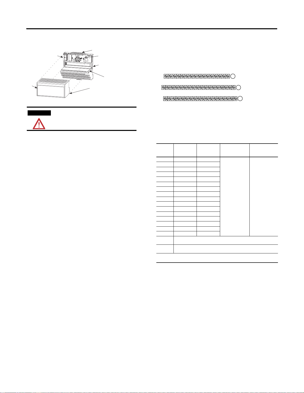
Installing Your Digital Input or Output Module
3
4
ATTENTION
During mounting of all devices, be sure that all
debris (metal chips, wire strands, etc.) is kept from
falling into the module. Debris that falls into the
module could cause damage on power up.
The input module mounts on a 1794-TB32 or -TB32S terminal base. The
output module mounts on a 1794-TB2, -TB3 or -TB3S terminal base.
1. Rotate the keyswitch (1) on the terminal base (2) clockwise to position
2 as required for this type of module.
2. Make certain the flexbus connector (3) is pushed all the way to the left
to connect with the neighboring termbase/adapter. You cannot install
the module unless the connector is fully extended.
3. Make sure the pins on the bottom of the module are straight so they
will align properly with the connector in the terminal base.
4. Position the module (4) with its alignment bar (5) aligned with the
groove (6) on the terminal base.
5. Press firmly and evenly to seat the module in the terminal base unit.
The module is seated when the latching mechanism (7) is locked into
the module.
Connecting Wiring for the 1794-IB16D (using 1794-TB32 or -TB32S
terminal base)
1. Connect individual input wiring (IN00-IN15) to terminals 0 thru 15
on the 0-15 row (A) as indicated in the table below.
2. Connect individual Sensor Power wiring (sensor power 0 thru 15) to
terminals 17 thru 32 on the 16-33 row (B) as indicated in the table
below. Do not connect to terminals 16 or 33.
3. Connect the associated +V2 dc power lead of the input device to the
corresponding terminal on the 34-51 row (C) for each input as
indicated in the table below. (The +V2 power terminals of row (C) are
internally connected together.)
4. Connect the associated input common (3-wire devices only) to the
corresponding terminal on the 34-51 row. (C) for each input as
indicated in the table below. (Commons are internally connected
together.)
5. Connect +V dc power to pin 43 (+V) on the 34-51 row (C).
6. Connect -V dc common to pin 44 (COM2) on the 34-51 row (C).
7. If daisychaining input wiring power to the next terminal base, connect
a jumper from terminal 49 (+V dc) on this base unit to the power
terminal on the next base unit (refer to the installation instructions for
the next terminal base unit).
8. If continuing input wiring common to the next base unit, connect a
jumper from terminal 50 (common) on this base unit to the common
7
1
2
6
5
terminal on the next base unit (refer to the installation instructions for
the next terminal base unit).
1794-TB32 and -TB32S Terminal Base Wiring for the
1794-IB16D
17 18 19 20 21 22 23 24 25 26 27 28 29 30 31 32 33
16
NC NC
35 36 37 38 39 40 41 42 43 44 45 46 47 48 49 50 51
34
NC
+V1 COM1 +V1 COM1 +V1 COM1 +V1 COM1 +V2 COM2 +V2 COM2 +V2 COM2 +V2 COM2 NC
V2 = Terminals 43, 45, 47 and 49 -
Voltage applied to Inputs 0-15 and Sensor power 0-15
OM1, COM2 = Terminals 36, 38, 40, 42, 44, 46, 48 and 50 -
Common for inputs 0 thru 15 and sensor power 0 thru 15
C = No connections (terminals 16, 33, 34 and 51)
V1 = Terminals 35, 37, 39 and 41 (not used)
Input Terminals 0-15
Sensor Power Terminals 0-15
(1794-TB32 shown)
A
B
C
Wiring for 1794-IB16D (use with 1794-TB32 or -TB32S terminal
base units)
Input Input
Terminal
IN 00 A-0 B-17 -V common
IN 01 A-1 B-18
IN 02 A-2 B-19
IN 03 A-3 B-20
IN 04 A-4 B-21
IN 05 A-5 B-22
IN 06 A-6 B-23
IN 07 A-7 B-24
IN 08 A-8 B-25
IN 09 A-9 B-26
IN 10 A-10 B-27
IN 11 A-11 B-28
IN 12 A-12 B-29
IN 13 A-13 B-30
IN 14 A-14 B-31
IN 15 A-15 B-32
+V2 dc
power
COM dc
Return
1
use input, sensor power and common terminals.
Power terminals 43, 45, 47 and 49 (power terminals are internally connected
together in the module)
Common terminals 36, 38, 40, 42, 44, 46, 48 and 50 (common terminals are
internally connected together in the module)
3-wire devices only. 2-wire devices use input and sensor power terminals; 3-wire devices
Sensor
Power
Ter m in al
Common
connected to
terminals 36, 38, 40,
42, 44, 46, 48 and
50
1
Supply
+V2 connected to
terminals 43, 45,
47 and 49
Connecting Wiring for the 1794-OB16D (using 1794-TB2, -TB3 or
-TB3S terminal base)
1. Connect individual output wiring to numbered terminals on the 0-15
row (A) as indicated in the table below.
2. Connect the associated common for each output to the corresponding
terminal on the 16-33 row (B) as indicated in the table below. (The
common terminals of row (B) are internally connected together.)
3. Connect +V dc power to terminal 34 on the 34-51 row (C). (The
power terminals of row (C) are internally connected together.)
4. Connect dc common (COM) to terminal 16 on the 16-33 row (B).
5. If daisychaining power to the next terminal base, connect a jumper
from terminal 51 (+V dc) on this base unit to terminal 34 on the next
base unit.
Publication 1794-IN096B-EN-P - February 2004
Page 3

3
n)
6. If continuing dc common to the next base unit, connect a jumper
from terminal 33 (common) on this base unit to terminal 16 on the
next base unit
1794-TB2, -TB3, and -TB3S Terminal Base Wiring for the
1794-OB16D
0 1 2 3 4 5 6 7 8 9 10 11 12 13 14 15
17 18 19 20 21 22 23 24 25 26 27 28 29 30 31 32 33
16
-V
Common
35 36 37 38 39 40 41 42 43 44 45 46 47 48 49 50 51
34
Voltage
In +V
-V (Supply Common) = Terminals B-16 thru B-33
+V (Supply +Voltage In) = Terminals C-34 thru C-51
(Use B-33 and C-51 for daisy-chaining to next terminal base unit)
Terminals 35 thru 50 not available on 1794-TB2
Outputs
Commons
Voltage
A
B
-V
Common
Voltage
Out +V
(1794-TB3 show
C
Wiring Connections for the 1794-OB16D (use with 1794-TB2,
-TB3 or -TB3S terminal base units)
Outputs Output Terminal Common Terminal
Output 00 A-0 B-17
Output 01 A-1 B-18
Output 02 A-2 B-19
Output 03 A-3 B-20
Output 04 A-4 B-21
Output 05 A-5 B-22
Output 06 A-6 B-23
Output 07 A-7 B-24
Output 08 A-8 B-25
Output 09 A-9 B-26
Output 10 A-10 B-27
Output 11 A-11 B-28
Output 12 A-12 B-29
Output 13 A-13 B-30
Output 14 A-14 B-31
Output 15 A-15 B-32
+V dc C-34 and C-51 (1794-TB2) (Power Terminals are internally connected in
Common B-16 thru B-33 (Common terminals are internally connected in the
the terminal base unit.
C-34 thru C-51 (1794-TB3, -TB3S) (Power terminals are internally
connected in the terminal base unit.
terminal base unit.
.
Diagnostics
(See configuration information below for location of diagnostic bits.)
Note: Each unused sensor port requires a dummy resistor to mask the
channel diagnostic function.
Diagnostic Functions for the 1794-IB16D)
Ext.
Wiring Input
Power
OFF Open Off Off 0 0 0 0/OFF
Short Off Off 0 0 0 0/OFF
Normal Off Off 0 0 0 0/OFF
ON Open Off RED 1 0 0 1/RED
Short Off RED 0 1 0 1/RED
Normal Off Off 0 0 0 0/OFF
REV Open Off Off 0 0 1 1/RED
Short Off Off 0 0 1 1/RED
Normal Off Off 0 0 1 1/RED
The module monitors each sen sor-power port for current and voltage. It turns on the ch annel red LED and sets
(1) the error bit when 1) the module d etects a short circuit (no voltage at the sensor-port), and 2) the modu le
detects an open wire ( no c urrent at the sensor-port).
Diagnostic Functions for the 1794-OB16D
Note: Each unused output port requires a dummy resistor to mask
the channel diagnostic function.
Ext.
Power
The module monitors each output channel. It turns on the channel red LED and sets (1) the error bit when 1)
the module detects a short ci rcuit (the output signal is active at a channel and the correspond ing output
voltage is low), and 2) the modul e detects an open wire (the output signal is inactive at a channe l and the
corresponding output voltage is high).
Wiring Output
OFF Open Off Off 0 0 0 0/OFF
Short Off Off 0 0 0 0/OFF
Normal Off Off 0 0 0 0/OFF
ON Open Off RED 1 0 0 1/RED
Short Off Off 0 0 0 0/OFF
Normal Off Off 0 0 0 0/OFF
REV Ope n Off Off 0 0 1 1/ RED
Short Off Off 0 0 1 1/RED
Normal Off Off 0 0 1 1/RED
Channel
Status
On Off 0 0 0 0/OFF
On Off 0 0 0 0/OFF
On Off 0 0 0 0/OFF
On RED/YEL 1 0 0 1/RED
On RED/YEL 0 1 0 1/RED
On YEL 0 0 0 0/OFF
On Off 0 0 1 1/RED
On Off 0 0 1 1/RED
On Off 0 0 1 1/RED
Status
LED
Status
Channel
Status
On Off 0 0 0 0/OFF
On Off 0 0 0 0/OFF
On Off 0 0 0 0/OFF
On YEL 0 0 0 0/OFF
On RED 0 1 0 1/RED
On YEL 0 0 0 0/OFF
On Off 0 0 1 1/RED
On Off 0 0 1 1/RED
On Off 0 0 1 1/RED
LED
Open
Wire
Error Bit
Open
Wire Error
Bit
Short
Error
Bit
Short
Error
Bit
Rev.
Error
Bit
Rev.
Error
Bit
Module
Error
Bit/LED
Module
Error
Bit/LED
Publication 1794-IN096B-EN-P - February 2004
Page 4

4
Sensor Diagram for the 1794-IB16D
External
3-Wire
3-Wire
Sensor
Sensor
3-Wire
3-Wire
Sensor
Sensor
3-Wire
3-Wire
Sensor
Sensor
External
External
Power
Power
Supply
Supply
External
External
Power
Power
Supply
Supply
+
_
+
_
Unused input port Dummy resistor needed or
Fault LED remains lighted.
1794-IB16D
1794-IB16D
Sensor-power lines -
Sensor-power lines Detect open wire
Detect open wire
Detect short circuit
Detect short circuit
1794-IB16D
1794-IB16D
Dummy
Dummy
Resistor
Resistor
20kΩ, ≥1/8W
2-Wire
2-Wire
Sensor
Sensor
2-Wire
2-Wire
Sensor
Sensor
Shunt
Shunt
Resistor
Resistor
20kΩ, ≥1/8W
Shunt
Shunt
Resistor
Resistor
20kΩ, ≥1/8W
External
Power
Power
Supply
Supply
External
External
Power
Power
Supply
Supply
+
_
+
_
1794-IB16D
1794-IB16D
Sensor-power lines -
Sensor-power lines Detect open wire
Detect open wire
1794-IB16D
1794-IB16D
Sensor Diagram for the 1794-OB16D
External
Power
Supply
Load
Unused input port Dummy resistor needed or
Fault LED remains lighted.
1794-OB16D
Dummy
Resistor
Configuration
Configuring Your 1794-IB16D Input Module
Configure your input module by setting bits in the configuration word
(word 3). This module is compatible with the Remote I/O network
(with 1794-ASB series E or later), DeviceNet network, and the
ControlNet network. (Note: You must use the Module Connection
when used in a ControlNet system.)
Dec. 15 14 13 12 11 10 9 8 7 6 5 4 3 2 1 0
Oct. 17 16 15 14 13 12 11 10 7 6 5 4 3 2 1 0
Read 1 I 15I14I13I12I11I10I9I8I7I6I5I4I3I2I1I
Read 2 Read Diagnosti cs Status
Write 3 Not used Input Filter FT
Where I = Inp ut
FT = Input filter time
Diagnostic st atus;
Bit 00 = module error;
Bit 01 = external power reverse polarity error;
Bit 02 = sensor power short error;
Bit 03 = sens or power open wire error
0-15
Not used
Setting the Input Filter Time
To set the input filter time, set the associated bits in the output image
(complementary word) for the module.
#O:010
1
Dec.
Write FT to complement
of input module.
= 5 Octal or 5 Decimal
15 14 13 12 11 10 9 8 7 6 5 4 3 2 1 0
O:010
1794-IB16D
Write filter time on system startup.
I:000
00
FT = 0-15
1794-IB16D
FLL
Fill File
Source
Destination
Length
12 11 10 9 8 7 6 5
01
1
0
Bits Description Filter Time
10 09 08 Filter time for inputs 0 thru 15
0 0 0 Filter time 0 (default) 0.25ms
0 0 1 Filter time 1 0.5ms
0 1 0 Filter time 2 1ms
0 1 1 Filter time 3 2ms
1 0 0 Filter time 4 4ms
1 0 1 Filter time 5 8ms
1 1 0 Filter time 6 16ms
1 1 1 Filter time 7 32ms
Off to On/
On to Off
Configuring Your 1794-OB16D Output Module
Configure your output module by setting bits in the configuration
word (word 3). This module is compatibility with the Remote I/O
network (with 1794-ASB series D or later), DeviceNet network, and
the ControlNet network. (Note: You can use the Module Connection
or Rack Connection when used in a ControlNet system.)
Dec. 15 14 13 12 11 10 9 8 7 6 5 4 3 2 1 0
Oct. 17 16 15 14 13 12 11 10 7 6 5 4 3 2 1 0
Read 1 Not used Read Diagnosti cs Status
Write 2 O15O14O13O12O11O10O9O8O7O6O5O4O 30 2O 1O
Where O = Ou tput
Diagnostic st atus;
Bit 00 = module error;
Bit 01 = external power reverse polarity error;
Bit 02 = out put short error;
Bit 03 = output open wire error
0
Specifications
Specifications - 16 Input Module w/Diagnostics, 1794-IB16D
Meets IEC 3 24V dc input specification s
Number of Inputs 16 (1 group of 16), group isola tion
Module Location Cat. No. 1794-TB32, -TB32S
On-state Voltage 10V dc minimum
On-state Current 2 .0mA minimum at 10V dc
Off-state Voltage 5.0V dc maximum
Off-state Current 1.5mA minimum
Input Impedance 3.1K ohms
Indicators (field side
indication, customer device
driven)
Input Filter Time
Off to On
On to Off
Isolation Voltage Tested at 2121V dc for 1s b etween user and system
Power Dissipation 8.5W maximum @ 31.2V dc
Thermal Dissipation Maximum 29 BTU/hr @ 31.2V dc
Sensor
Power Voltage Drop
Power Current
Power Line
Short Detect Circuit
Open Wire Detect
Detect Reverse Polarity
Volt age
Flexbus Current 30mA
24V dcnominal
31.2V dc maximum
8.2mA nominal at 24V dc
12.1mA maximum at 31.2V dc (See Derating Curve)
16 yellow ON/OFF status indicators (field side)
16 red diagnostic status in dicators (each channel, field side)
1 red module fault indicator (field side)
0.25ms, 0.5ms, 1ms, 2ms , 4ms, 8ms, 16ms, 32ms
0.25ms, 0.5ms, 1ms, 2ms , 4ms, 8ms, 16ms, 32ms
0.25ms default - Selectable us ing configuration word 3
No isolation between individua l channels
2.2V dc maximum
50mA maximum
1.0A minimum (in 10s)
50µA maximum
Minimum 10V: Module must detect if the r everse polarity external
power supply voltage is greater than the value.
Publication 1794-IN096B-EN-P - February 2004
Page 5

5
Specifications - 16 Output Module w/Diagnostics 1794-OB16D
Meets IEC 0.5A 24V dc Output Specificatio ns
Number of Outputs 16 (1 g roup of 16), group isolat ion
Module Location Cat. No. 1794-TB2, -TB3, -TB3S
Output Voltage 10V dc minimum
On-state Current 2.0mA minimum per output
Output Current Rating 8.0A (16 outputs @ 0.5A)
Surge Current 2A for 50ms, repeatable every 2s
Off-state Voltage 31.2V dc maximu m
Off-state Leakage 0.5mA maximum
On-state Voltage Drop 0.5V dc at 0.5A
Isolation Voltage Tested at 2121V dc for 1s bet ween user and system
Indicators (field side
indication, customer device
driven)
Flexbus Current 60mA
Power Dissipation 4.8W maximum @ 31.2V dc
Thermal Dissipation Maximum 16. 4 BTU/hr @ 31.2V dc
Short Circuit Protect and
Detection
Open Wire Detect off-state
leakage current
Detect Reverse Polarity
Volt age
24V dc nominal
31.2V dc maximum
0.5A per output, 8A per module maximum
No isolation between individual ch annels
16 yellow on/off status indicators (field side)
16 red diagnostic status indic ators (each channel, field side)
1 red module fault indicator (field side )
Thermal shutdown (auto reset)
Detection condition: when exter nal power active, output signal
active, and output port voltage les s than 2V.
0.1mA - When external power activ e and output signal inactive.
10V minimum: Module must detect if t he reverse polarity external
power supply voltage is greater th an the value.
General Specifications
Module Keying Position 2
Terminal Base Screw
Torque
Dimensions (with module
installed)
External dc power
Supply voltage
Voltage range
Environmental Conditions
Operating Temperature IEC 60068-2-1 (Test Ad, Operating Cold),
Storage Temperature IEC 60068-2-1 (Test Ab, Un-packaged Non-operating Cold),
Relative Humidity IEC 60068-2-30 (Test Db, Un-packaged Non- operating
Vibration IEC60068-2-6 (Test Fc, Operating):
Shock IEC60068-2-27 (Test Ea, Unpackaged shock)
Emissions CISPR 11:
ESD Immunity IEC 61000-4-2:
Radiated RF Immunity IEC 61000-4-3:
7 pound-inches (0.8Nm)
1.8H x 3.7W x 2.1D inches
45.7H x 94.0W x 53.3D mm
24V dc nominal
10.0 to 31.2V dc (includes 5% ac ri pple)
IEC 60068-2-2 (Test Bd, Operating Dry Heat),
IEC 60068-2-14 (Test Nb, Operating Thermal Shock):
0 to 55°C (32 to 131°F)
IEC 60068-2-2 (Test Bb, Un-packaged Non-operating Dry Heat ),
IEC 60068-2-14 (Test Na, Un-packaged Non-operating Therma l
Shock):
–40 to 85°C (–40 to 185°F)
Damp Heat):
5 to 95% non-condensing
5g @ 10-500Hz
Operating 30g
Non-operating 50g
Group 1, Class A (with appropriate enclosure)
6kV contact discharges
8kV air discharges
10V/m with 1kHz sine-wave 80%AM from 80MHz to 2000MHz
10V/m with 200Hz 50% Pulse 100%AM at 900Mhz
10V/m with 200Hz 50% Pulse 100%AM at 1890Mhz
EFT/B Immunity IEC 61000-4-4:
Surge Transient
Immunity
Conducted RF Immunity IEC 61000-4-6:
Enclosure Type Rating None (open-style)
Conductors Wire Size
Category
Certifications (when
product is marked)
1 You use this category information for plannin g conductor routing as described in Allen-Brad ley
publication 17 70-4.1, Industrial Autom ation Wiring and Grou nding Guidelines.
2 For the latest up-to-dat e information, see the Pr oduct Certification l ink at www.ab.com for Declar ations of
Conformity, Certifica tes and other certifi cation details. For notif ication of any addition al release notes, refer to
www.ab.com/manuals/.
±2kV at 5kHz on signal ports
±2kV at 5kHz on power ports
IEC 61000-4-5:
±1kV line-line(DM) and ±2kV line-ea rth(CM) on signal ports
±1kV line-line(DM) and ±2kV line-ea rth(CM) on power ports
10Vrms with 1kHz sine-wave 80 %AM from 150kHz to 80MHz
12AWG (4mm2) stranded copper wire rated at 75°C or higher
3/64 inch (1.2mm) insulation maximum
1
2
CULUS UL Listed Industrial Control Equipm ent, certified for US and
2
Canada
CULUS UL Listed for Class I, Division 2, G roups A, B, C and D
Hazardous locations certifie d for US and Canada
CSA CSA certified for Class I, Division 2, Groups A, B, C and D
Hazardous locations
CE2 European Union 89/336/EEC EMC Direct ive,
compliant with:
EN 61000-6-4; Industrial Emissions
EN 50082-2; Industrial Immunity
EN 61326; Meas./Control/Lab., Indust rial Requirements
EN 61000-6-2; Industrial Immunity
C-Tick2 - Australian Radiocommunications Act compliant with
AS/NZS CISPR 11, Industrial Emissions
Derating Curves
1794-IB16D Input Voltage
31.2
30
26.4
25
20
Input
Voltage
15
(V)
10
5
0
Sensor Power
50
40
Sensor
Power
30
Current
(m A)
20
10
0
10 20 30 40 50 55
Ambient Temperature (˚C)
10 20 30 40 50 55
Ambient Temperature (˚C)
45
Publication 1794-IN096B-EN-P - February 2004
Page 6

Publication 1794-IN096B-EN-P - February 2004 6 PN 957867-05
Supersedes Publication 1794-IN096A -EN-P - November 2003 and 1794-RN063A-EN-P - December 2003 Copyright © 2004 Rockwell Automatio n, Inc. All rights reserved. Printed in the U.S.A.
 Loading...