

Page 1
Installation Instructions
FLEX Integra
2 Input/2 Protected Output Module
(Cat. No. 1793-IB2XOB2P and -IB2XOB2PS)
41355
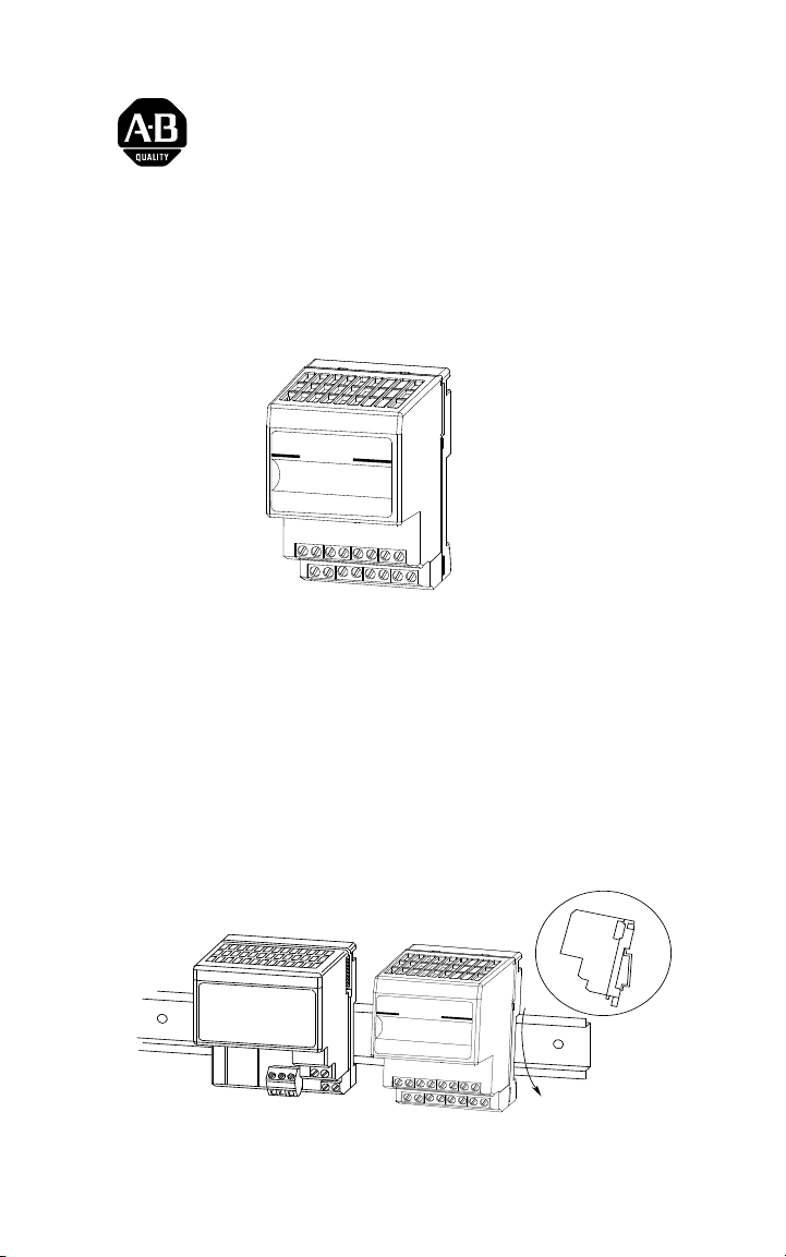
Module Installation
This module mounts on a DIN rail. It connects to an adapter or another
FLEX I/O or Integra module. Note: If using this module with FLEX I/O
modules, do not mount between FLEX I/O modules. Mount Integra
modules to the right of the FLEX I/O modules. To mount this module:
1. Remove the cover plug (if used) in the male connector of the unit to
which you are connecting this module.
2. Position the module on the 35 x 7.5mm DIN rail A (A-B pt. no.
199-DR1).
3. Rotate the module onto the DIN rail with the top of the rail hooked
under the lip on the rear of the module.
A
A
30720-M
FLEX Integra and FLEX I/O are
trademarks of Rockwell Automation Publication 1793-5.3 - September 1999
Page 2
2 FLEX Integra 2 Input/2 Protected Output Module
41377
A
41370
41371
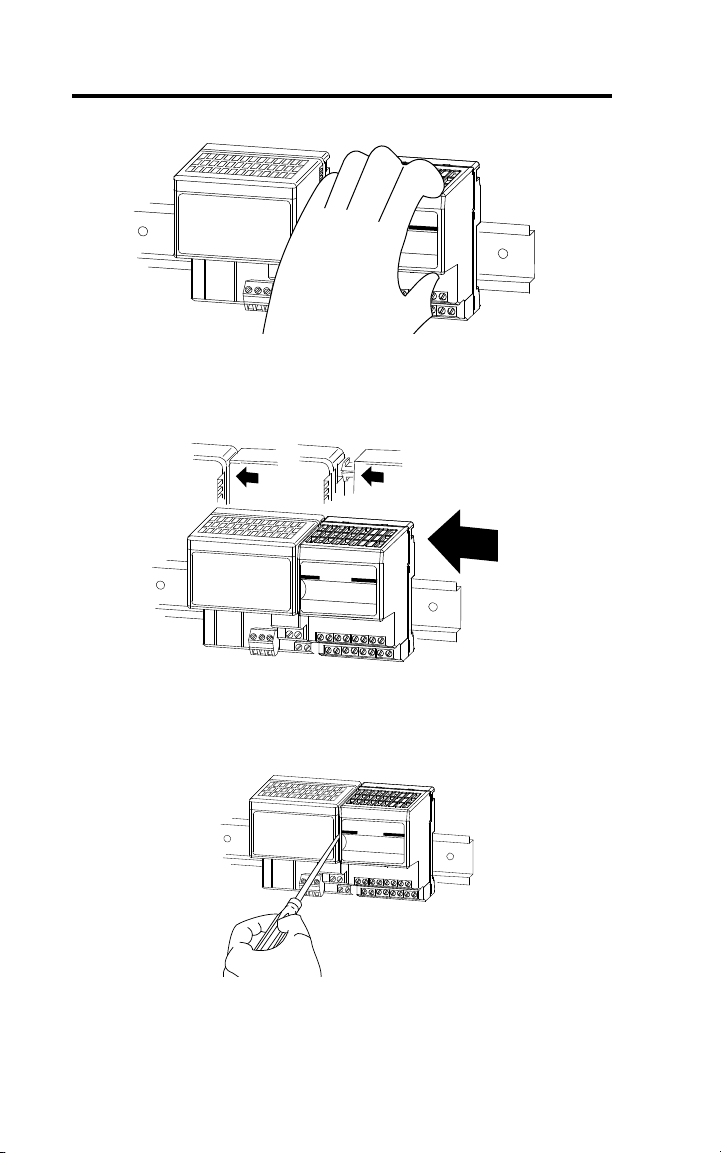
4. Press down to lock the module on the DIN rail.
If the module does not lock in place, use a screwdriver of similar
device to move the locking tab down, press the module flush with the
DIN rail and release the locking tab to lock the module in place.
5. Firmly push the module into the adjacent module/terminal base until
the units lock together.
6. Repeat the above steps to install the next module.
7. To remove an Integra module, you must work from the right side and
remove one module at a time. To disengage a module from its
neighbor, place a common flat-bladed screwdriver between the 2
modules and turn 1/4 turn to separate the modules.
41373
8. Then slide the module away from its left neighbor, and release the
locking lever to remove the module from the DIN rail.
Publication 1793-5.3 - September 1999
Page 3

FLEX Integra 2 Input/2 Protected Output Module 3
ATTENTION: Do not remove this module under
power. Removing this module under power will break the
!
electrical backplane (flexbus) connections. This can cause
personal injury or property damage by:
• sending an erroneous signal to your system's field
devices causing unintended machine motion
• causing an explosion in a hazardous environment
• breaking communication to modules beyond this
module
European Union Directive Compliance
If this product has the CE mark it is approved for installation within the
European Union and EEA regions. It has been designed and tested to meet
the following directives.
EMC Directive
This product is tested to meet Council Directive 89/336/EEC
Electromagnetic Compatibility (EMC) and the following standards, in
whole or in part, documented in a technical construction file:
• EN 50081-2 EMC - Generic Emission Standard, Part 2 - Industrial
Environment
• EN 50082-2 EMC - Generic Immunity Standard, Part 2 - Industrial
Environment
This product is intended for use in an industrial environment.
Low Voltage Directive
This product is tested to meet Council Directive 73/23/EEC Low Voltage,
by applying the safety requirements of EN 61131-2 Programmable
Controllers, Part 2 - Equipment Requirements and Tests.
For specific information required by EN 61131-2, see the appropriate
sections in this publication, as well as the following Allen-Bradley
publications:
• Industrial Automation Wiring and Grounding Guidelines For Noise
Immunity, publication 1770-4.1
• Automation Systems Catalog, publication B111
This equipment is classified as open equipment and must be mounted in an
enclosure during operation to provide safety protection.
Publication 1793-5.3 - September 1999
Page 4
4 FLEX Integra 2 Input/2 Protected Output Module
0 123456 7
8 9 10 11 12 13 14 15
A
B
41469
CV CV
CCVVCCVV
OOII
Ch 0
Ch 1
Ch 0
Ch 1
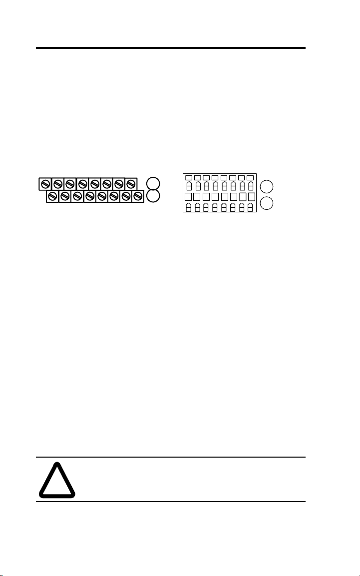
Wiring
This module is available with 2 styles of terminations; 1794-IB2XOB2P screw-cage and 1793-IB2XOB2PS - spring-clamp. Refer to the wiring
figure below.
1793-IB2XOB2P 1793-IB2XOB2PS
Ch 1
Ch 1
Ch 0
Ch 0
CV CV
01234567
8 9 10 11
Where: C - common, V = + voltage, I = input, O = output
1. Connect individual sensor input leads to terminals 2 (channel 0) and 3
(channel 1) on row A.
2. Connect sensor supply lead to +24V dc (terminals 1, 6, 9, or 14).
(Terminals 1, 6, 8, 9, 14 and 15 are connected internally to +24V dc.)
3. Connect associated input common (3-wire sensors only) to terminals
10 and 11 on row B.
4. Connect individual output wiring to terminals 4 (channel 0) and 5
(channel 1) on row A.
5. Connect associated output common to terminals 12 and 13 on row B.
6. Connect +24Vdc voltage to terminal 8 on row B
7. Connect 24V dc common to terminal 0 on row A.
8. If daisy-chaining +24V dc from this module to the next FLEX Integra
module, connect a jumper from terminal 15 to terminal 8 on the next
FLEX Integra module.
9. If daisy-chaining 24V dc common from this module to the next FLEX
Integra module, connect a jumper from terminal 7 on this module to
terminal 0 on the next Integra module.
.
OOII
A
B
CCVVCCVV
13 14 1512
41468
!
Publication 1793-5.3 - September 1999
ATTENTION: Total current draw through the module’s
(+) voltage terminals is limited to 10A. Separate power
connections to the module may be required.
Page 5

FLEX Integra 2 Input/2 Protected Output Module 5
Wiring
Channel
Sink Input
1
Input Terminal Supply Terminal
021
136
Source Output Output Terminal Common
0412
1513
+24V dc Terminals 1, 6, 8, 9, 14, 15 are internally
connected together in the module.
24V dc common Terminals 0, 7, 10 thru 13 are internally
connected together in the module
1 Two-wire devices use signal input and power terminals, 3-wire devices use
signal input, supply and common terminal s.
Example of 2-wire and 3-wire Sensors
123456
0
8
9 10 11121314
7
15
3-Wire Sensor
2-Wire Sensor
41338
Indicators
24V DC 2x2 DIGITAL COMBO
iNPUT OUTPUT
0
A
A = Status indicators - shows status of individual outputs
B = Insertable label for writing individual output designations
1793-IB2XOB2PS
1
1
0
41339
B
Publication 1793-5.3 - September 1999
Page 6

6 FLEX Integra 2 Input/2 Protected Output Module
Memory Mapping
Bit/
15 14 13 12 11 10 09 08 07 06 05 04 03 02 01 00
Word
Read Reserved I1 I0
Write Reserved O1 O0
Write Reserved FT time
Where: I = Input
O = Output
FT = Filter time
Setting the Input Delay Time
You can select the input delay time (DT) for input channels 00 and 01.
Select the input delay time by setting the corresponding bits in the
configuration word (word 3) for the module.
For example, to set a delay time of 4ms for an input module at address rack
1, module group 0, set bits 02, 01 and 00 as shown below.
Input Delay Times
02 01 00 Filter Time for Inputs 00-01
000Filter Time 0 (default) 512
001Filter Time 1 1ms
010Filter Time 2 2ms
011Filter Time 3 4ms
100Filter Time 4 8ms
101Filter Time 5 16ms
110Filter Time 6 32ms
111Filter Time 7 64ms
Publication 1793-5.3 - September 1999
Selected
Filter Time
μ
s
Page 7

FLEX Integra 2 Input/2 Protected Output Module 7
CUL Hazardous Location Approval
CUL certifies products for general use as well as
for use in hazardous locations. Actual CUL
certification is indicated by the product label
as shown below, and not by statements in any
user documentation.
Example of the
CUL
certification
product label
To comply with CUL certification for use in
hazardous locations, the following information
becomes a part of the product literature for this
CUL-certified industrial constrol product.
•
This equipment is suitable for use in Class
I, Division 2, Groups A, B, C, D, or
non-hazardous locations only.
•
The products having the appropriate CUL
markings (that is, Class I, Division 2, Groups
A, B, C, D) are certified for use in other
equipment where the suitability of
combination (that is, application or use) is
determined by the CUL or the local
inspection office having jurisdiction
Important: Due to the modular nature of a
CUS
programmable control system, the
product with the highest temperature
rating determines the overall
temperature code rating of a
programmable control system in a Class
I, Division 2, location. The temperature
code rating is marked on the product
label as shown.
CL I, DIV 2
GP A,B,C,D
TEMP
Approbation d’utilisation dans des
environnements dangereux par la CUL
La CUL certifie des produits pour une utilisation
générale aussi bien que pour une utilisation en
environnements dangereux. La certification CUL
en vigueur est indiquée par l'étiquette produit et
non par des indications dans la documentation
utilisateur.
Exemple
d'étiquette de
certification
d'un produit
par la CUL
EPour satisfaire à la certification CUL en
environnements dangereux, les informations
suivantes font partie intégrante de la
documentation des produits de commande
industrielle certifiés.
•
•
Importa nt: De par la nature modulaire des systèmes
CUS
Cet équipement ne convient qu’à une
utilisation dans
des environnements de Classe I, Division 2,
Groupes A, B, C, D ou non dangereux.
Les produits portant le marquage CUL
approprié (c'est-à-dire Classe I, Division 2,
Groupes A, B, C, D) sont certifiés pour une
utilisation avec d'autres équipements, les
combinaisons d’applications et d’utilisation
étant déterminées par la CUL ou le bureau
local d'inspection.
de commande programmables, le prod uit
ayant le code de température le plus élevé
détermine le code de température global
du système dans un environnement de
Classe I, Division 2. Le code de
température est indiqué sur l'étiquette
produit.
7HPSHUDWXUHFRGHUDWLQJ &RGHGHWHPSpUDWXUH
CL I, DIV 2
CUS
GP A,B,C,D
TEMP
CUS
CL I, DIV 2
Look for temperature
code rating here.
GP
A,B,C,D
/
e code de température
est indiqué ici.
CL I, DIV 2
GP A,B,C,D
TEMP
The following warnings apply to products having
CUL certification for use in hazardous locations.
Les avertissements suivants s'appliquent aux
produits ayant la certification CUL pour une
utilisation dans des environnements dangereux.
Publication 1793-5.3 - September 1999
Page 8

8 FLEX Integra 2 Input/2 Protected Output Module
CUL Hazardous Location Approval
$77(17,21 ([SORVLRQ+D]DUG
Substitution of components may impair
•
suitability for Class I, Division 2.
•
Do not replace components unless power
has been switched off or the area is known
to be non-hazardous.
•
Do not disconnect equipment unless power
has been switched off or the area is known
to be non-hazardous.
•
Do not disconnect connectors unless
power has been switched off or the area is
known to be non-hazardous. Secure any
user-supplied connectors that mate to
external circuits on this equipment by using
screws, sliding latches, threaded
connectors, or other means such that any
connection can withstand a 15 Newton (3.4
lb.) separating force applied for a minimum
of one minute.
•
Batteries must only be changed in an area
known to be non-hazardous.
CUL logo is a registered trademark of the
Underwriters Laboratories.
Approbation d’utilisation dans des
environnements dangereux par la CUL
$9(57,66(0(175LVTXHGH[SORVLRQ
La substitution de composants peut rendre
•
ce matériel inadapté à une utilisation en
environnement de
Classe I, Division 2.
•
Couper le courant ou s'assurer que
l’environnement est classé non dangereux
avant de remplacer des composants.
•
Couper le courant ou s’assurer que
l’environnement est classé non dangereux
avant de débrancher l'équipement.
•
Couper le courant ou s'assurer que
l’environnement est classé non dangereux
avant de débrancher les connecteurs. Fixer
tous les connecteurs fournis par l'utilisateur
pour se brancher aux circuits externes de cet
appareil à l 'aide de vis, loquets coulissants,
connecteurs filetés ou autres, de sorte que
les connexions résistent à une force de
séparation de 15 Newtons (1,5 kg - 3,4 lb.)
appliquée pendant au moins une minute.
•
S'assurer que l'environnement est classé
non dangereux avant de changer les piles.
Le sigle CUL est une marque déposée de la
Underwriters Laboratories.
Publication 1793-5.3 - September 1999
Page 9

FLEX Integra 2 Input/2 Protected Output Module 9
Specifications - 2 Input/2 Protected Output Module Cat. No. 1793-IB2XOB2P
and -IB2XOB2PS
Module Type 2 input/2 output digital combination w/electronic fusing
1793-IB2XOB2P - screw-clamp terminations
1793-IB2XOB2PS - spring-clamp terminations
Module Location DIN rail mounting
Number of Channels 2 digital input - sinking/2 digital output - sourcing,
protected
Input
On-state Voltage 10-31.2V dc; 24V dc nominal
On-state Current 2-12 mA; 8mA @ 24V dc
Off-state Voltage 5V dc maximum
Off-state Current 1.5mA minimum
Channel Impedance 4.6K
Ω
Isolation Voltage Channel to system - 850V dc for 1s
Channel to channel - None
Input Delay - selectable
Off to On
On to Off
512μs, 1, 2, 8, 16, 32 or 64ms
512μs, 1, 2, 8, 16, 32 or 64ms
Default = 512μs
Output
On-state Voltage 10-31.2V dc; 24V dc nominal
On-state Current 1-500mA per channel
Off-state Voltage 31.2V dc maximum
Off-state Current 0.5mA maximum leakage
Channel Impedance 1.0Ω (0.5V dc maximum drop)
Surge Current 1.5A for 50ms, repeatable every 2s
Isolation Voltage Channel to system - 850V dc for 1s
Channel to channel - None
Delay Time Off to On
On to Off
0.5ms maximum
1.0ms maximum
General
Flexbus Current 20mA maximum
Power Dissipation 1.4W @ 31.2V dc
Thermal Dissipation 4.8 BTU/hr @ 31.2V dc
Indicators 4 yellow channel status indicators
External dc Power Voltage
Current
19.2-31.2V dc (5% ac ripple)
40mA maximum
Publication 1793-5.3 - September 1999
Page 10

10 FLEX Integra 2 Input/2 Protected Output Module
Specifications - 2 Input/2 Protected Output Module Cat. No. 1793-IB2XOB2P
and -IB2XOB2PS
Dimensions in
2.72H x 3.15D x 2.17W
(mm)
(69H x 80D x 55W)
Fusing Outputs electronically fused
Environmental Conditions
Operational Temperature
Storage Temperature
Relative Humidity
Shock Operating
Nonoperating
Vibration
Conductors Wire Size
Category
o
C (32 to +131oF)
0 to +55
-40 to +85
o
C (-40 to +185oF)
5 to 95% noncondensing
Tested to 30g peak acceleration, 11(+
Tested to 50g peak acceleration, 11(+
Tested 5g @ 10-500Hz per IEC68-2-6
2
12 gauge (4mm
) stranded wire
3/64 in (1.2mm) maximum insulation
2
1)ms pulse width
1)ms pulse width
Screw Terminal Torque 7-9 lb-in
Agency Certification
(when product is marked)
• CUL Listed
• CUL Class I, Division 2 Groups A, B, C and D certified
• UL listed
• CE marked for all applicable directives
1 Use this categor y information for planning conductor routing as described in publication 1770-4.1, “Wiring and
Grounding Guidelines for Noise Immunity.”
Publication 1793-5.3 - September 1999
Page 11

FLEX Integra 2 Input/2 Protected Output Module 11
Publication 1793-5.3 - September 1999
Page 12

Publication 1793-5.3 - September 1999 PN 955132-32A
Supersedes Publication 1793-5.3 - September 1998 © (1999) Rockwell International Corporation.Printed in USA
 Loading...