

Page 1
Installation Instructions
Cat. No. 1792-IB2XOB2E Series B
To: See page:
Install
the ArmorBlock Module
Connect the Wiring to the ArmorBlock Module
Communicate with Y
Configure Y
Manager Configuration T
Configure Y
Manager Configuration T
Reset Faults 25
Configure Y
For this reference information
Default Configuration
Status indicators
Troubleshooting 32
Specifications 34
our ArmorBlock Module
our ArmorBlock Module Of
ool
our ArmorBlock Module Online Using the DeviceNet
ool
our ArmorBlock Module with EDS Files
fline Using the DeviceNet
3
8
10
11
17
27
See page:
14
32
This 1792 ArmorBlock I/O block module (Cat. No. 1792-IB2XOB2E)
contains I/O circuits, a built-in power supply, and a built-in DeviceNet
I/O adapter. Because of its sealed housing, this 1792 I/O block requires
no enclosure. It is compatible with PLC or SLC programmable
controllers using DeviceNet scanners. The I/O values are accessible
from the PLC or SLC programmable controller data table.
This ArmorBlock module has no switches to set. You set module
parameters using the DeviceNet Manager Software (cat. no.
1787-MGR) or similar configuration tool.
ArmorBlock is a trademark of Allen-Bradley Co. Inc.
Publication 1792-5.5 – October 1996
Page 2

ArmorBlock 2 Input/2 Output Module2
European Union Directive Compliance
If this product is installed within the European Union or EEA regions
and has the CE mark, the following regulations apply.
EMC Directive
This apparatus is tested to meet Council Directive 89/336/EEC
Electromagnetic Compatibility (EMC) using a technical construction
file and the following standards, in whole or in part:
• EN 50081-2 EMC – Generic Emission Standard, Part 2 –
Industrial Environment
• EN 50082-2 EMC – Generic Immunity Standard, Part 2 –
Industrial Environment
The product described in this manual is intended for use in an industrial
environment.
Low Voltage Directive
This apparatus is also designed to meet Council Directive 73/23/EEC
Low Voltage, by applying the safety requirements of EN 61131–2
Programmable Controllers, Part 2 – Equipment Requirements and
Tests.
For specific information that the above norm requires, see the
appropriate sections in this manual, as well as the following
Allen-Bradley publications:
• Industrial Automation Wiring and Grounding Guidelines,
publication 1770-4.1
• Automation Systems Catalog, publication B111
Publication 1792-5.5 – October 1996
Page 3
ArmorBlock 2 Input/2 Output Module
Install Your ArmorBlock Module
Installation of the ArmorBlock module consists of:
• setting the node address in the ArmorBlock module
• mounting the ArmorBlock module
• connecting the wiring
• communicating with your module
• configuring the parameters
Set the Node Address
Each ArmorBlock comes with its internal program set for node address
63. To set the node address, you need the following:
• host computer with DeviceNet Manager Software (or similar
configuration software tool)
• 1770-KFD RS-232 module (or similar interface)
• suitable cables to connect the 1770-KFD to your module and to
connect the 1770-KFD to your host computer
3
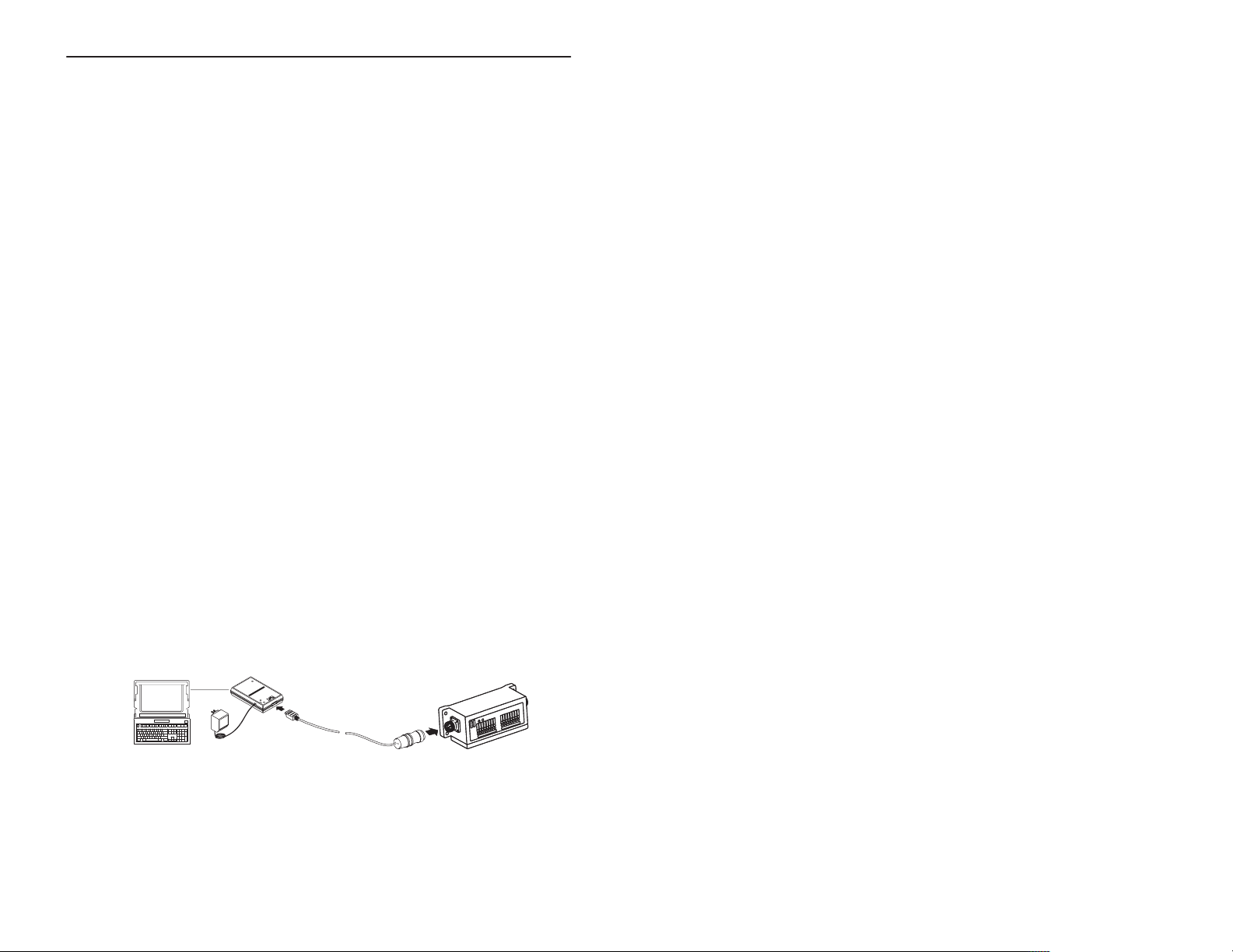
Set the node address to meet your system requirements as follows:
1. Set up a system (as shown below) to communicate with your
ArmorBlock module.
Power
from 9V DC Power-Supply Adapter
1770-KFD
RS-232 module
open style connector to
sealed mini-female cable
host computer with the
DeviceNet Manager software
power supply
Publication 1792-5.5 – October 1996
Page 4
ArmorBlock 2 Input/2 Output Module4
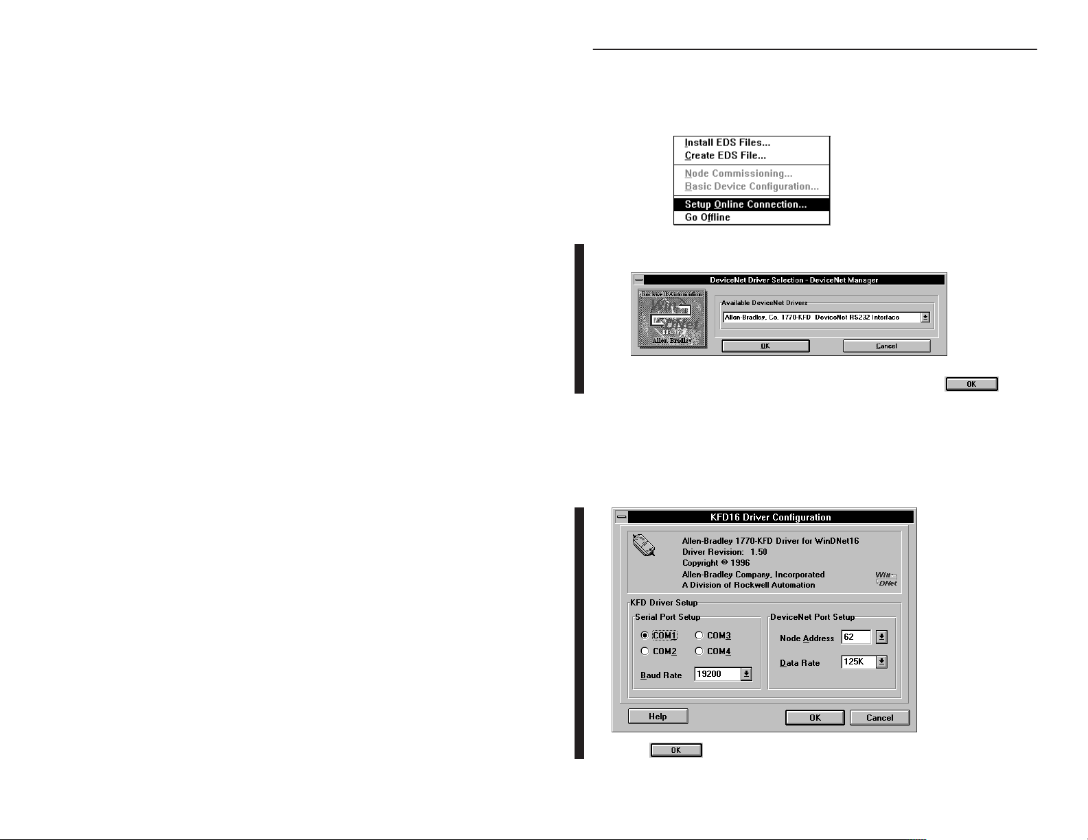
2. Using DeviceNet Manager Software, go online using the “Setup
Online Connection” selection on the utility pulldown menu.
3. The DeviceNet Driver selection screen appears.
Select the driver for your application and click on .
4. The Driver configuration screen lets you:
• set the data rate
• set the interface adapter node address
• select the interface adapter serial port
• set interface adapter baud rate
Click on to go online.
Publication 1792-5.5 – October 1996
Page 5
ArmorBlock 2 Input/2 Output Module
5
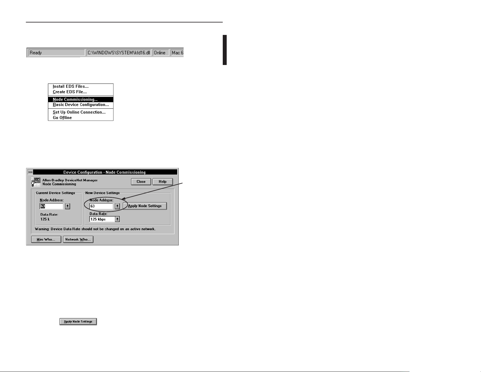
5. The bar at the bottom of the screen will tell you when you go online.
6. At the utility pulldown, select “Node Commissioning.”
7. You can set the node address on the “Device Configuration – Node
Commissioning” screen. Note that the node address “out of the box”
setting is 63. Set the desired node address per your system
requirements.
Set new node
address here.
You can also set the data rate on this screen, if required. However,
your module is shipped with the “autobaud” parameter enabled.
This assures that the module will be at the correct data rate for any
network to which it is connected. To change the data rate, you must
first disable autobaud on the parameter screen, then return to the
“Device Configuration – Node Commissioning” screen and enter
the new data rate.
8. Click on
to apply the new node settings.
9. Repeat the above procedure to set the node addresses of any
additional ArmorBlock modules you want to install.
Publication 1792-5.5 – October 1996
Page 6

ArmorBlock 2 Input/2 Output Module6
Mount the ArmorBlock Module
Mount the block module directly to the machine or device. Complete
mounting dimensions are shown below. Note that the block dimensions
allow direct connection of a T-port tap (cat. no. 1485P-P1N5-j) to the
DeviceNet connector. (Refer to publication 1485-6.7.1 for cabling
details.)
The ArmorBlock module has a sloping top and a gap at the rear to
allow water or other liquids to run off during washdowns. The flow
through the gap prevents buildup of debris under the block.
Preferred mounting position is with the microconnectors pointing
down. However, the block can be mounted in any orientation.
Publication 1792-5.5 – October 1996
Page 7
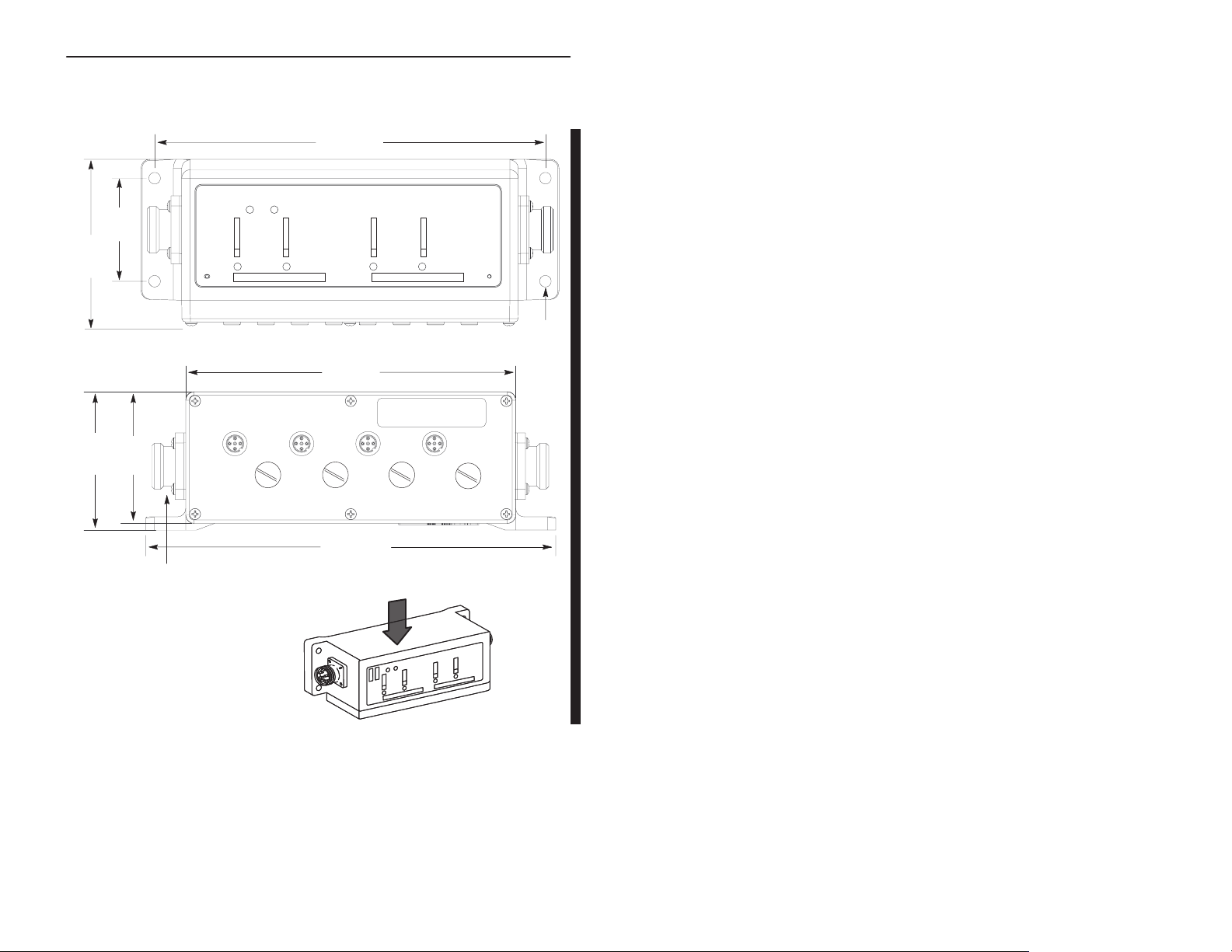
Mounting Dimensions
.
1.90
(48.3)
3.055
(77.6)
Inches
(Millimeters)
2.63
(66.7)
2.5
(63.5)
ADDRESS
NODE
ArmorBlock 2 Input/2 Output Module
25
7
7
(184.2)
ARMORBLOCK
MOD/NET
INPUT
STATUS
FAULT
TE
RA
DATA
1792-IB2XOB2E
I/O
4
mounting holes
for #10 screws
6.24
(158.5)
Block dimensions allow T
-port tap
connection directly onto connector
For washdown installations,
or excessively moist areas,
mount block with micro
connectors down.
7.74
(196.6)
Direction
of liquid flow
Publication 1792-5.5 – October 1996
Page 8
ArmorBlock 2 Input/2 Output Module8
Connect the Wiring to the ArmorBlock Module
The block module uses quick disconnect, screw-on style connectors
for:
• I/O input wiring
• I/O output wiring
• power wiring for I/O outputs
• the DeviceNet connector
DeviceNet
mini connector
2 micro connectors for output wiring
0101
Output power
mini connector
2 micro connectors for input wiring
4 micro plugs – these
seal unused ports
Micro plugs are included with your module. Use these plugs to cover
and seal unused ports.
Pinout diagrams for these connectors are shown below.
ATTENTION: All connectors must be securely
tightened to properly seal the connections against leaks
!
Publication 1792-5.5 – October 1996
and maintain NEMA 4X and 6P requirements.
Page 9

ArmorBlock 2 Input/2 Output Module
Connecting the Input Wiring
Connect input wiring to the micro connectors which screw into mating
connectors on the side of the block.
Make connections as shown below.
I/O Input Micro Connector
9
4
1
3
2
(View into socket)
Pin 1 = Sensor Source Voltage Positive
Pin 2 = Not used
Pin 3 = Negative/Return
Pin 4 = Signal
Connecting the Output Wiring
Connect individual output wiring to micro connectors which screw into
mating connectors on the side of the block. Make connections as shown
below.
I/O Output Micro Connector
4
1
3
2
(View into socket)
Connect the output power wiring to the 3-pin mini connector on the end
of the block.
Important: The
Output Power Mini Connector
outputs use electronic overcurrent fault protection. Make certain
your output power supply can handle overcurrent events.
Pin 1 = Not used
Pin 2 = Not used
Pin 3 = Negative
Pin 4 = Output
1
23
(View into pins)
Pin 1 = Not used
Pin 2 = Positive
Pin 3 = Negative
Publication 1792-5.5 – October 1996
Page 10

ArmorBlock 2 Input/2 Output Module10
Connecting the DeviceNet Wiring
Connect DeviceNet wiring to the 5-pin mini connector on the end of
the block. Connections are shown below.
DeviceNet Mini Connector
Pin 1 = Drain (Bare)
1
2
3
(View into pins)
5
4
Pin 2 = V+ (Red)
Pin 3 = V– (Black)
Pin 4 = CAN–HI (White)
Pin 5 CAN–LO (Blue)
Note: Colors are
DeviceNet standard
Communicate with Your ArmorBlock Module
This ArmorBlock module acts as a slave in a master/slave environment.
It is both a “polled device” and a “change of state device.”
When configured as a polled device, a master initiates communication
by sending its polled I/O message to the ArmorBlock module. The 2
input/2 output module scans the inputs and fault bits producing a
response, and consumes the message, updates outputs, and produces a
response that reflects their status.
When configured as a “change of state” device, productions occur
when an input changes, or an output fault occurs. If neither has
occurred within the “expected packet rate,” a heartbeat production
occurs. This heartbeat production tells the scanner module that the
ArmorBlock module is alive and ready to communicate.
Publication 1792-5.5 – October 1996
Page 11

ArmorBlock 2 Input/2 Output Module
11
Bit
Produces IS Reserved OF1 OF0 I1 I0
Consumes Reserved O1 O0
Where: I = Input
IS = Sensor source voltage fault
O = Output
OF = Output fault
Word Bit Description
Produces
Consumes
00–01 Input bits – bit 00 corresponds to input 0, bit 01 to input 1. When the
02–03 Output fault bits – Shows fault status of each output. OS0
04–06 Reserved
07 Sensor source voltage fault bit – this bit is set (1) when the sensor
00–01 Output bits – Bit 00 corresponds to output 0, bit 01 corresponds to
02–07 Reserved
07 06 05 04 03 02 01 00
bit is set (1), the input is on.
corresponds to output 0, and OS1 corresponds to output 1. When
the bit is set (1), the output is faulted.
source voltage is faulted.
output 1. 0 = output off; 1 = output on
Configure Your Armor Module Offline Using the
DeviceNet Manager Configuration Tool
To configure your ArmorBlock module offline:
• add the device to the network
• set the parameters for the device
• save the parameters to a file
Note: You cannot actually configure your device offline. You can set
and save the parameters to a file for downloading to the device when
you go online.
Publication 1792-5.5 – October 1996
Page 12

ArmorBlock 2 Input/2 Output Module12
Adding a Device to the Network
Action Response
At
the network screen, click on the
“add device” button.
At the “add device to network”
screen, click on “discrete I/O” in
the device type box.
Then click on the desired ArmorBlock device.
Select the device node
address for this device.
Click on the OK button when you have selected your device.
Add more devices as necessary.
Publication 1792-5.5 – October 1996
Page 13

ArmorBlock 2 Input/2 Output Module
13
Configure your Device Parameters
After adding the devices to the network, you must configure them. You
have 2 choices:
• highlight the device, and click on the button, or
• double-click on the device to bring up the device configuration
screen.
For detailed device information on this device, click on .
Publication 1792-5.5 – October 1996
Page 14

ArmorBlock 2 Input/2 Output Module14
Configuring the Parameters
Default settings for the 2 in/2 out module are:
autobaud when
of
f to on delay
on to of
f delay
fault state
idle state
reset faulted I/O reset sensor source voltage and faulted outputs
enabled, matches device baud rate to network baud
rate at powerup
time from a valid input signal to recognition by the block
module
time from input signal dropping below the valid level to
recognition by the block module
defines output behavior during a communication fault
defines output behavior during program mode
1. Double click on the parameter you want to change.
enable
no delay
no delay
reset outputs
reset outputs
nothing selected
The parameter screen appears.
Publication 1792-5.5 – October 1996
Page 15

ArmorBlock 2 Input/2 Output Module
15
2. Click on the radio button to select a different setting. To save the
setting, click on
. To cancel any changes, click on
.
3. For help about a specific parameter, click on
. A screen
similar to this will appear. To continue, click on
4. Continue with any additional parameters you want set for your
block module. The 2 input/2 output module has the following
additional parameters: off to on delay, on to off delay, idle state,
fault state, and reset faulted I/O..
When you have completed each parameter selection, click on the
button. This returns you to the device configuration
screen.
You can save these parameters to a file for downloading to the device
when online, or print them to a text file for hard copy use.
Publication 1792-5.5 – October 1996
Page 16

ArmorBlock 2 Input/2 Output Module16
Saving to a File
1. To save those parameters to a file, click on the
button.
You see this screen.
2. Choose the file name, file type (.dcf), directory, and drive to which
you want to save the file.
3. Click on the
button to save.
Printing to a Text File
1. If you choose to save your changes to a text file, click on the
button.
A screen similar to the following will appear.
Publication 1792-5.5 – October 1996
Page 17

ArmorBlock 2 Input/2 Output Module
2. Choose the file name, file type (.TXT), directory and drive to which
you want to save the file.
17
3. Click on the
hard copy for future reference.
button to save. Use this file to print out as
Online Help
Online help is available on all screens. Click on to
bring up pertinent information concerning the device configuration you
are selecting.
Additionally, help is available on each parameter screen by clicking on
.
Configure Your Armor Module Online Using the
DeviceNet Manager Configuration Tool
The procedure for online configuration is similar to the offline
configuration procedure previously described. You must:
• establish the interface to the network
• add the device to the network from the Add Device to Network
screen
• access and configure the device parameters
Establish the Interface
1. Select the “set up online connection” at the Utilities pulldown menu.
Publication 1792-5.5 – October 1996
Page 18

ArmorBlock 2 Input/2 Output Module18
2. The configuration screen for your selected driver appears. You can:
• set the node address
• set the data rate
• select the interface adapter serial port
• set the interface adapter baud rate
3. After setting the parameters, click on the button. The
system will automatically go online, as shown at the bottom of the
screen.
Online
will also appear in the Network area.
Publication 1792-5.5 – October 1996
Page 19

Add the Device to the Network
Action Response
At
the network screen, click on the
“add device” button.
At the “add device to network”
screen, click on “discrete I/O” in
the device type box.
ArmorBlock 2 Input/2 Output Module
19
Important: The
screen (from the Utilities pulldown menu). See page 3.
Then click on the desired ArmorBlock device.
Select the device node
address for this device.
Click on the OK button when you have selected your device.
Add more devices as necessary.
node address can only be set at the “Node Commissioning”
Publication 1792-5.5 – October 1996
Page 20

ArmorBlock 2 Input/2 Output Module20
4. Click once on the device you wish to configure on the project screen
and choose
.
The device configuration screen appears.
If you have Parameter Status is
Not previously modified default settings Default Values
Modified parameters but have not saved them Modified
Modified and saved parameter settings Current
Clicked on “Load from File” File Values
Clicked on “Load from Device” Device Values
Publication 1792-5.5 – October 1996
Page 21

5. Load parameters.
If you want to load parameters Choose
From a file
You see this screen.
Choose the drive, file type, and directory to
load the file from.
Select the file name so that it is highlighted
and choose
Note: The product code, type and
revision must be identical in order to load
a file from one device to another.
From the selected device
ArmorBlock 2 Input/2 Output Module
21
From default settings
Publication 1792-5.5 – October 1996
Page 22

ArmorBlock 2 Input/2 Output Module22
6. Modify the parameter.
If you want to Choose
Modify a parameter
You
Click on the settings you wish to activate.
T
o save these settings,
choose
T
o save these settings to the device,
choose
see a screen similar to this one.
o use default settings,
T
choose
T
o cancel any changes,
choose
For help about a specific parameter
parameter and then
choose
You can view parameters online by clicking on
Any changes that occur for a parameter will be reflected
on the screen.
Publication 1792-5.5 – October 1996
, click on the
Page 23

ArmorBlock 2 Input/2 Output Module
7. Save parameters to a file, to the device, or print to a file.
If you want to Choose
Save parameters
to a file
You
see this screen.
23
Select the drive, file type, directory
would like to save and choose
, and file name to which you
Save parameters to
the selected device
Print to a file
You
see this screen.
Select the drive, file type, directory
would like to save and choose
, and file name to which you
8. To exit from the Enhanced Configuration screen,
click on
.
Publication 1792-5.5 – October 1996
Page 24

ArmorBlock 2 Input/2 Output Module24
Monitoring
Parameters Online
You can monitor parameters at the Device Configuration screen or at
the selected parameter screen.
The start monitor button on the Device Configuration screen allows
you to monitor all of the parameters online. To monitor parameters:
Click on the
button to start the
monitor.
The monitor function starts after a few seconds.
1.The status line
flashes “monitoring.”
2.The monitoring function
is indicated by an
asterisk moving down
next to the parameters.
3.The monitor button changes to and
only “modify parameter” and “stop monitoring” are active.
4.Click on the button to stop monitoring.
To monitor an individual parameter:
1. Select the parameter on the Device Configuration screen.
2. Highlight the parameter and click on “Modify Parameter.”
3. Click on “Start Monitor” on the individual parameter screen.
Publication 1792-5.5 – October 1996
Page 25

ArmorBlock 2 Input/2 Output Module
Reset Faults
There are various ways to reset faults on an ArmorBlock module.
• cycle power to the module by disconnecting, then reconnecting the
DeviceNet connector
• use the Reset Faulted I/O feature on the parameter screen
• use the explicit message program control feature
• for output faults, remove and reconnect the output power connector
ATTENTION: If you reset a fault by removing and
replacing the output power connector, outputs
!
(including the faulted output) will be on when power
is reconnected.
25
Note: This
Reset Faults Online Using the Parameter Screen
To reset faults online, return to the network screen and proceed as
follows:
module contains a circuit to protect the DeviceNet power supply from short
circuits in an attached sensor or sensor cable. If you connect a sensor while the
module is powered, the surge current produced by the sensor can cause the
module to fault. This operation is normal. If this occurs, reset the module.
1.Click on the faulted device.
2.Then click on the Configure
Device button.
Publication 1792-5.5 – October 1996
Page 26

ArmorBlock 2 Input/2 Output Module26
The device configuration screen appears. Select the Reset Faulted I/O
parameter.
After selecting
the parameter, click on the
modify parameter button.
The configuration screen for the selected parameter appears.
1.Click on the faulted
output to reset.
2.Then click on the
OK button to apply.
3.You will be returned to
the configuration screen.
Click on ”Save to Device”
to apply the change.
Publication 1792-5.5 – October 1996
Page 27

ArmorBlock 2 Input/2 Output Module
Header
Body
Reset Faults using Explicit Message Program Control
You can also reset inputs and outputs using the Explicit Message
Program Control feature on the Scanner module master. Refer to the
specific scanner publications for information on using this feature.
The format for the reset explicit message transaction block must
contain 6 words as shown below:
Word Input Fault Output Fault
27
Transaction
Transaction
Word 0TXID – CMD/ST
W
ord 1
PORT – SIZE PORT – SIZE
W
ord 2
Service = 32 hex – MAC ID Service = 32 hex – MAC ID
W
ord 3
Class = 1D hex Class = 9
W
ord 4
Instance = 1
W
ord 5
Attribut Data = 0 Attribut Data = 0
ATUS
TXID – CMD/ST
Instance = n – where n = number
of the output (1 or 2)
ATUS
Configure Your Armor Module Using EDS Files
Current versions of DeviceNet Manager software include ArmorBlock
module support. If you are using a version of DeviceNet Manager
software that does not include ArmorBlock module Electronic Data
Sheets (EDS) files in its library, you can use the following information
to create the file.
If you are using a configuration tool other than DeviceNet Manager,
you can also use the following information to create the EDS file.
(Note: This EDS file was current at the time of printing. Contact your
nearest district office for information on later files.)
$ Electronic Data Sheet for Armor Block I/O (1792–IB2XOB2E)
[File]
DescText = ”1792–IB2XOB2E Armor Block I/O EDS File”;
CreateDate = 04–18–96;
CreateTime = 12:00:00;
ModDate = 09–17–96;
ModTime = 16:00:00;
Revision = 2.1; $ EDS revision.
[Device]
VendCode = 1;
Publication 1792-5.5 – October 1996
Page 28

ArmorBlock 2 Input/2 Output Module28
VendName = ”Allen–Bradley Company, Inc.”;
ProdType = 7;
ProdTypeStr = ”General Purpose Discrete I/O”;
ProdCode = 1028;
MajRev = 2;
MinRev = 1;
ProdName = ”Armor Block I/O 2 input / 2 output”;
Catalog = ”1792–IB2XOB2E”;
UCMM = 0; $ UCMM is not supported.
[IO_Info]
Default = 0x0001; $ The default I/O type is polled I/O.
PollInfo =
0x0001, $ Polled I/O device.
1, $ Input1 entry is the default input connection.
1; $ Output1 entry is the default output connection.
Input1 =
1, $ The size in bytes that this connection produces.
0, $ All bits of this connection are significant.
0x0001, $ Only Polled I/O is compatible.
”IB2XOB2E Production Data”, $ Name of Connection.
6, $ Path length.
”20 04 24 64 30 03”, $ Path to I/O Production Assembly.
”This connection contains input data at bits 0 and 1, output status at bits 2 and 3, and
sensor source voltage status at bit 7.”;
Output1 =
1, $ The size in bytes that this connection consumes.
2, $ Only the two least significant bits of this
0x0001, $ Only Polled I/O is compatible.
”IB2XOB2E Consumption Data”, $ Name of Connection.
6, $ Path length.
”20 04 24 20 30 03”, $ Path to I/O Consumption Assembly.
”This connection contains data for two outputs.”;
$$$$$$$$$$ Help string $$$$$$$$$$$
$ connection are used.
$$$$$$$$$$ Help string $$$$$$$$$$$
[ParamClass]
MaxInst = 11; $ 6 configurable and 5 read–only parameters.
Descriptor = 0x09; $ Stub param instances in eeprom.
CfgAssembly = 0x68; $ The config assembly is instance #104 of assy obj.
[Params]
$$$$$$$$$$$$$$$$$$$$$$$$$$$$$$$$$$$$$$$$$$$$$$$$$$$$$$$$$$$$$$$$$$$$$
$$$$$$$$$$
Param1 = $ Disable Autobaud
0, $ reserved
6, $ Link Path Size
”20 03 24 01 30 64”, $ Link Path to disable autobaud attribute.
0x0002, $ No support for settable path, scaling, scaling links, or
4, $ Data Type – boolean
1, $ Data Size
”Autobaud”, $ Parameter Name
””, $ Units String
$$$$$$$$$$ Help string $$$$$$$$$$$
Publication 1792-5.5 – October 1996
$ real time update of value. Value is gettable and
$ Settable. Enumerated strings are supported.
Page 29

ArmorBlock 2 Input/2 Output Module
”Enable takes effect after next powerup. Disable is required to set fixed baud rate, no
power cycle is required.”,
0,1,0, $ Min, Max, and Default values
1,1,1,0,0,0,0,0,0; $ Not Used
$$$$$$$$$$$$$$$$$$$$$$$$$$$$$$$$$$$$$$$$$$$$$$$$$$$$$$$$$$$$$$$$$$$$$
$$$$$$$$$$
Param2 = $ Input filter Off_to_On Delay selection
0, $ reserved
6, $ Link Path Size
”20 0F 24 02 30 01”, $ Link Path to param instance. The param instance
$ decodes the enumerated parameter into engineering
$ units (micro seconds).
0x0002, $ No support for settable path, scaling, scaling links,
$ or real time update of value. Value is gettable and
$ Settable. Enumerated strings are supported.
2, $ Data Type – unsigned int
2, $ Data Size – (in bytes)
”Off–to–On Delay”, $ Parameter Name
”ms”, $ Units String
$$$$$$$$$$ Help string $$$$$$$$$$$
”Signal must be present for this delay period before module detects the change.”,
0,4,0, $ Min, Max (max enumeration #), and Default values
1,1,1,0,0,0,0,0,0; $ Not Used
$$$$$$$$$$$$$$$$$$$$$$$$$$$$$$$$$$$$$$$$$$$$$$$$$$$$$$$$$$$$$$$$$$$$$
$$$$$$$$$$
Param3 = $ Input filter On_to_Off Delay selection
0, $ reserved
6, $ Link Path Size
”20 0F 24 03 30 01”, $ Link Path to param instance. The param instance
decodes
$ the enumerated parameter into engineering units
$ (micro seconds).
0x0002, $ No support for settable path, scaling, scaling links,
$ or real time update of value. Value is gettable and
$ Settable. Enumerated strings are supported.
2, $ Data Type – unsigned int
2, $ Data Size – (in bytes)
”On–to–Off Delay”, $ Parameter Name
”ms”, $ Units String
$$$$$$$$$$ Help string $$$$$$$$$$$
”Signal must be present for this delay period before module detects the change.”,
0,4,0, $ Min, Max (max enumeration #), and Default values
1,1,1,0,0,0,0,0,0; $ Not Used
$$$$$$$$$$$$$$$$$$$$$$$$$$$$$$$$$$$$$$$$$$$$$$$$$$$$$$$$$$$$$$$$$$$$$
$$$$$$$$$$
Param4 = $ Fault State selection
0, $ reserved
6, $ Link Path Size
”20 1E 24 01 30 07”, $ Link Path to DOG object’s fault state attribute.
0x0002, $ No support for settable path, scaling, scaling links,
$ or real time update of value. Value is gettable and
$ Settable. Enumerated strings are supported.
4, $ Data Type – boolean
1, $ Data Size
”Fault State”, $ Parameter Name
””, $ Units String
$$$$$$$$$$ Help string $$$$$$$$$$$
Publication 1792-5.5 – October 1996
29
Page 30

ArmorBlock 2 Input/2 Output Module30
”Defines output behavior in the event of a communication fault.”,
0,1,0, $ Min, Max (max enumeration #), and Default values
1,1,1,0,0,0,0,0,0; $ Not Used
$$$$$$$$$$$$$$$$$$$$$$$$$$$$$$$$$$$$$$$$$$$$$$$$$$$$$$$$$$$$$$$$$$$$$
$$$$$$$$$$
Param5 = $ Idle State selection
0, $ reserved
6, $ Link Path Size
”20 1E 24 01 30 09”, $ Link Path to DOG object’s idle state attribute.
0x0002, $ No support for settable path, scaling, scaling links,
4, $ Data Type – boolean
1, $ Data Size
”Idle State”, $ Parameter Name
””, $ Units String
$$$$$$$$$$ Help string $$$$$$$$$$$
”Defines output behavior during program mode.”,
0,1,0, $ Min, Max (max enumeration #), and Default values
1,1,1,0,0,0,0,0,0; $ Not Used
$$$$$$$$$$$$$$$$$$$$$$$$$$$$$$$$$$$$$$$$$$$$$$$$$$$$$$$$$$$$$$$$$$$$$
$$$$$$$$$$
Param6 = $ Reset Faulted I/O
0, $ reserved
6, $ Link Path Size
”20 0F 24 06 30 01”, $ Link Path to param instance.
0x0002, $ No support for settable path, scaling, scaling links,
8, $ Data Type – unsigned short int
1, $ Data Size – (in bytes)
”Reset Faulted I/O”, $ Parameter Name
””, $ Units String
$$$$$$$$$$ Help string $$$$$$$$$$$
”This resets the voltage supplied to sensors or a faulted output. A reset will only be
accepted if a fault exists.”,
0,3,0, $ Min, Max (max enumeration #), and Default values
1,1,1,0,0,0,0,0,0; $ Not Used
$$$$$$$$$$$$$$$$$$$$$$$$$$$$$$$$$$$$$$$$$$$$$$$$$$$$$$$$$$$$$$$$$$$$$
$$$$$$$$$$
Param7 = $ Input 1 value
0, $ reserved
6, $ Link Path Size
”20 08 24 01 30 03”, $ Link Path to Input 1 value attribute.
0x0030, $ No support for settable path, scaling, or scaling
8, $ Data Type – unsigned short int
1, $ Data Size – (in bytes)
”Input 1 Value”, $ Parameter Name
””, $ Units String
$$$$$$$$$$ Help string $$$$$$$$$$$
”This parameter is the current value of Input 1.”,
0,1,0, $ Min, Max, and Default values
1,1,1,0,0,0,0,0,0; $ Not Used
$ or real time update of value. Value is gettable and
$ Settable. Enumerated strings are supported.
$ or real time update of value. Value is gettable and
$ Settable. Enumerated strings are supported.
$ links.
$ Value is gettable only. Enumerated strings are not
$ supported.
Publication 1792-5.5 – October 1996
Page 31

ArmorBlock 2 Input/2 Output Module
$$$$$$$$$$$$$$$$$$$$$$$$$$$$$$$$$$$$$$$$$$$$$$$$$$$$$$$$$$$$$$$$$$$$$
$$$$$$$$$$
Param8 = $ Input 2 value
0, $ reserved
6, $ Link Path Size
”20 08 24 02 30 03”, $ Link Path to Input 2 value attribute.
0x0030, $ No support for settable path, scaling, or scaling
$ links.
$ Value is gettable only. Enumerated strings are not
$ supported.
8, $ Data Type – unsigned short int
1, $ Data Size – (in bytes)
”Input 2 Value”, $ Parameter Name
””, $ Units String
$$$$$$$$$$ Help string $$$$$$$$$$$
”This parameter is the current value of Input 2.”,
0,1,0, $ Min, Max, and Default values
1,1,1,0,0,0,0,0,0; $ Not Used
$$$$$$$$$$$$$$$$$$$$$$$$$$$$$$$$$$$$$$$$$$$$$$$$$$$$$$$$$$$$$$$$$$$$$
$$$$$$$$$$
Param9 = $ Input status
0, $ reserved
6, $ Link Path Size
”20 1D 24 01 30 05”, $ Link Path to Dicrete Input Group status attribute.
0x0032, $ No support for settable path, scaling, or scaling
$ links.
$ Value is gettable only. Enumerated strings are
$supported.
8, $ Data Type – unsigned short int
1, $ Data Size – (in bytes)
”Input Status”, $ Parameter Name
””, $ Units String
$$$$$$$$$$ Help string $$$$$$$$$$$
”This parameter is the current status of all inputs.”,
0,1,0, $ Min, Max, and Default values
1,1,1,0,0,0,0,0,0; $ Not Used
$$$$$$$$$$$$$$$$$$$$$$$$$$$$$$$$$$$$$$$$$$$$$$$$$$$$$$$$$$$$$$$$$$$$$
$$$$$$$$$$
Param10 = $ Output 1 status
0, $ reserved
6, $ Link Path Size
”20 09 24 01 30 04”, $ Link Path to Output 1 status attribute.
0x0032, $ No support for settable path, scaling, or scaling
$ links.
$ Value is gettable only. Enumerated strings are
$supported.
8, $ Data Type – unsigned short int
1, $ Data Size – (in bytes)
”Output 1 Status”, $ Parameter Name
””, $ Units String
$$$$$$$$$$ Help string $$$$$$$$$$$
”This parameter is the current status of Output 1.”,
0,1,0, $ Min, Max, and Default values
1,1,1,0,0,0,0,0,0; $ Not Used
$$$$$$$$$$$$$$$$$$$$$$$$$$$$$$$$$$$$$$$$$$$$$$$$$$$$$$$$$$$$$$$$$$$$$
$$$$$$$$$$
Param11 = $ Output 2 status
Publication 1792-5.5 – October 1996
31
Page 32

ArmorBlock 2 Input/2 Output Module32
0, $ reserved
6, $ Link Path Size
”20 09 24 02 30 04”, $ Link Path to Output 2 status attribute.
0x0032, $ No support for settable path, scaling, or scaling
$ links.
$ Value is gettable only. Enumerated strings are
$ supported.
8, $ Data Type – unsigned short int
1, $ Data Size – (in bytes)
”Output 2 Status”, $ Parameter Name
””, $ Units String
$$$$$$$$$$ Help string $$$$$$$$$$$
”This parameter is the current status of Output 2.”,
0,1,0, $ Min, Max, and Default values
1,1,1,0,0,0,0,0,0; $ Not Used
[Groups]
Group1=”Configuration”,5,1,2,3,4,5;
Group2=”I/O”,6,6,7,8,9,10,11;
[EnumPar]
Param1=”Enable”,”Disable”;
Param2=”0 ms”,”2 ms”,”4 ms”,”8 ms”,”16 ms”;
Param3=”0 ms”,”2 ms”,”4 ms”,”8 ms”,”16 ms”;
Param4=”Reset Outputs”,”Hold Last State”;
Param5=”Reset Outputs”,”Hold Last State”;
Param6=”Nothing Selected”,”Output #1”,”Output #2”,”Sensor Source Voltage”;
Param9=”Healthy”,”Faulted”;
Param10=”Healthy”,”Faulted”;
Param11=”Healthy”,”Faulted”;
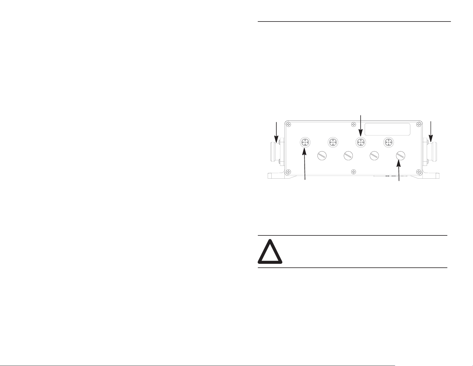
Troubleshoot with the Indicators
The ArmorBlock I/O module has 3 types of indicators:
• Mod/Net status indicator
• Input fault indicator
• individual I/O status indicators
Mod/Net Status Indicator
MOD/NET
STATUS
TE
RA
ADDRESS
DATA
NODE
Input I/O Status Indicators
Publication 1792-5.5 – October 1996
Input Fault Indicator
INPUT
FAULT
ARMORBLOCK
1792-IB2XOB2E
I/O
Output I/O Status Indicators
Page 33

ArmorBlock 2 Input/2 Output Module
33
Note: This module contains a circuit to protect the DeviceNet power supply from short circuits
in an attached sensor or sensor cable. If you connect a sensor while the module is
powered, the surge current produced by the sensor can cause the module to fault. This
operation is normal. If this occurs, reset the module (page 25).
Mod/Net
Status Indicator
Indication Status
No
power
OFF
Flashing Green/OFF
Solid Green
Flashing Red
Solid Red
Green to Red to Of
1
This only occurs when Autobaud is disabled, and the module is set to an incorrect baud rate.
Input
Fault Indicator
f
, or no network access, or incorrect baud rate
On-line but not connected
On-line, link okay
Recoverable fault
Critical failure, or duplicate node address present
At powerup only – The module is autobauding
, connected
1
Indication Status
Sensor
OFF
Solid Red
Input
I/O Status Indicator
source voltage operating correctly
1 or more Sensor source voltage shorts
Indication Status
OFF No
Yellow V
Output
I/O Status Indicator
valid input signal present
alid input signal present
Indication Status
OFF Output is off
Yellow
Red (see note)
Note: A faulted output may cause adjacent outputs to fault.
Output is on
Output is faulted
Publication 1792-5.5 – October 1996
Page 34

ArmorBlock 2 Input/2 Output Module34
Specifications
2 Input/2 Output Module – 1792-IB2XOB2E/B
Input Specifications
Inputs per Block 2 sinking
On-state Voltage Range 10–30V dc
On-state Current Maximum
Minimum
Off-state Voltage Maximum 5V dc
Off-state Current Minimum 1.5mA
Transition Voltage 5–10V dc
Transition Current 1.5–3.0mA
Input Impedance Maximum 5K ohms
Input Signal Delay Off to On
On to Off
Sensor Source Voltage
Current
Output Specifications
6.0mA @ 30V dc
2.0mA @ 10V dc
0ms, 2ms, 4ms, 8ms, 16ms
0ms, 2ms, 4ms, 8ms, 16ms
10–25V dc
50mA per point, 0.1A total per module
Outputs per Block 2 sourcing
Output Voltage Range 19 – 30V dc
On-state Voltage Maximum 0.25V dc @ rated current
On-state Current Maximum 2.0A per output @ 70oC
Module Current (all outputs on)
Maximum
Off-state Leakage Current
Maximum 1.5mA per output
Surge Current (per output)
Maximum 4.0A for 10ms, repeatable every 2s
Specifications continued on next page
Publication 1792-5.5 – October 1996
4.0A per module
1
Page 35

ArmorBlock 2 Input/2 Output Module
2 Input/2 Output Module – 1792-IB2XOB2E/B
General Specifications
Indicators Mod/Net Status – red/green
Input Fault – red
I/O Status – yellow/red (customer field side driven)
DeviceNet Power Voltage
Current
Surge Current at Power Up Less than 10A for 5ms
Dimensions Inches
Millimeters
Connectors 1792-IB2XOB2EA/B – Aluminum connectors
Power Dissipation Maximum 1.9 Watts
Thermal Dissipation Maximum 6.9 BTU/hr
Isolation Voltage 500V ac – outputs to DeviceNet
Specifications continued on next page
11.0 – 25.0V dc
100mA (no powered sensors)
200mA (full sensor load)
2.6H X 7.7W X 3.06D
66H X 195W X 77.7D
1792-IB2XOB2ES/B – Stainless Steel Connectors
500V ac – outputs to inputs
35
Publication 1792-5.5 – October 1996
Page 36

ArmorBlock 2 Input/2 Output Module36
•
2 Input/2 Output Module – 1792-IB2XOB2E/B
Environmental Conditions
Operational Temperature
Storage Temperature
Relative Humidity
Shock Operating
Non-operating
Vibration
Conductors Refer to publication 1485-6.7.1 for information on
Enclosure Meets or exceeds NEMA 4X and 6P, IP67
Agency Certification
(when product or packaging is marked)
1
Minimum wire size is 20 gauge.
This
product has been tested at an Open DeviceNet V
Inc. (ODV
A) authorized independent test laboratory and found to comply
with ODVA Conformance Test Software V
–25 to 70oC (–13 to 158oF)
–40 to 85
o
C (–40 to 185oF)
up to 100%
30 g peak acceleration, 11(+
50 g peak acceleration, 11(+
1)ms pulse width
1)ms pulse width
Tested 10 g @ 10–500Hz per IEC 68-2-6
cabling for your DeviceNet module.
o
1200psi, 140
F hosedown
• CSA certified
• CSA Class I, Division 2, Groups A, B, C, D
certified
• UL listed
• CE marked for all applicable directives
endor Association,
ersion FT 1.2/1.0.
Worldwide representation.
Argentina •
Colombia • Costa Rica • Croatia • Cyprus • Czech Republic • Denmark • Ecuador • Egypt • El Salvador
Finland •
Indonesia •
Mexico •
Puerto Rico • Qatar • Romania • Russia–CIS • Saudi Arabia • Singapore
Africa, Republic • Spain • Sweden
United Kingdom • United States • Uruguay • V
Allen-Bradley Headquarters, 1201 South Second Street, Milwaukee, WI 53204 USA,
Tel: (1) 414 382-2000 Fax: (1) 414 382-4444
Publication
Publication 1792-5.5 – October 1996
Supersedes
Australia • Austria • Bahrain • Belgium
France • Germany • Greece • Guatemala • Honduras • Hong Kong • Hungary • Iceland • India
Ireland • Israel • Italy • Jamaica •
Netherlands
1792-5.5 – October 1996
1792-5.5 – December 1995
• New
Zealand • Norway
• Switzerland • T
• Brazil •
Bulgaria • Canada • Chile • China, PRC
Japan • Jordan • Korea • Kuwait • Lebanon
• Pakistan •
enezuela • Y
Peru
• Philippines •
aiwan
• Thailand • T
ugoslavia
Copyright 1996 Allen-Bradley Company
Poland • Portugal
• Slovakia • Slovenia •
urkey • United Arab Emirates
• Malaysia •
•
South
PN955126–06
, Inc. Printed in USA
•
•
•
 Loading...