

Page 1
Installation Instructions
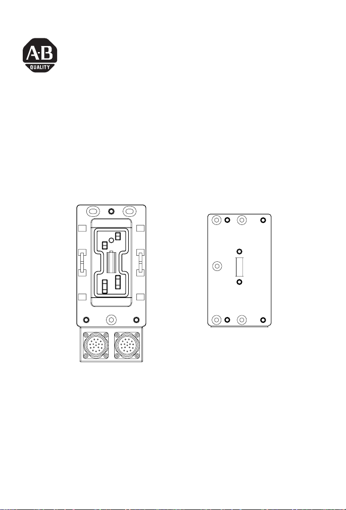
ArmorBlock MaXum Robot I/O Cable Base
and Kempf Box Plate
(Cat. No. 1792D-CB23 and -KPLT)
CB23
43333
The 23mm ArmorBlock MaXum Robot Ι/Ο Cable Base mates with 4
or 8 point modules, depending on your installation requirements, and
optionally the Kempf box plate. No modification is required. Modules
are interchangeable whether flat or round media cable bases are
used. This interchangeability provides plug and play block upgrade
capability and easy field replacement. The completely assembled
ArmorBlock module and base requires no enclosure.
Publication 1792D-IN054B-EN-P - April 2003
KPLT
43338
Page 2

2 ArmorBlock MaXum Robot I/O Cable Base and Kempf Box Plate
These instructions describe the installation of the cable base. The
catalog numbers for the cable base and Kempf box are:
• 1792D-CB23 (for 23mm trunk or drop cable installation)
• 1792D-KPLT (to mount the cable base on a Kempf box)
IMPORTANT
ArmorBlock MaXum modules and media cables
are ordered and shipped separately.
Important User Information
Because of the variety of uses for the products described in this
publication, those responsible for the application and use of these
products must satisfy themselves that all necessary steps have been
taken to assure that each application and use meets all performance
and safety requirements, including any applicable laws, regulations,
codes and standards. In no event will Rockwell Automation be
responsible or liable for indirect or consequential damage resulting
from the use or application of these products.
Any illustrations, charts, sample programs, and layout examples
shown in this publication are intended solely for purposes of
example. Since there are many variables and requirements associated
with any particular installation, Rockwell Automation does not
assume responsibility or liability (to include intellectual property
liability) for actual use based upon the examples shown in this
publication.
Allen-Bradley publication SGI-1.1, Safety Guidelines for the
Application, Installation and Maintenance of Solid-State Control
(available from your local Rockwell Automation office), describes
some important differences between solid-state equipment and
electromechanical devices that should be taken into consideration
when applying products such as those described in this publication.
Reproduction of the contents of this copyrighted publication, in
whole or part, without written permission of Rockwell Automation, is
prohibited.
Publication
1792D-IN054B-EN-P - April 2003
Page 3
ArmorBlock MaXum Robot I/O Cable Base and Kempf Box Plate 3
!
WARNING
ATTENTION
!
IMPORTANT
Throughout this publication, notes may be used to make you aware
of safety considerations. The following annotations and their
accompanying statements help you to identify a potential hazard,
avoid a potential hazard, and recognize the consequences of a
potential hazard:
Identifies information about practices or
circumstances that can cause an explosion in a
hazardous environment, which may lead to
personal injury or death, property damage, or
economic loss.
Identifies information about practices or
circumstances that can lead to personal injury or
death, property damage, or economic loss.
Identifies information that is critical for
successful application and understanding of the
product.
Publication
1792D-IN054B-EN-P - April 2003
Page 4
4 ArmorBlock MaXum Robot I/O Cable Base and Kempf Box Plate
Environment and Enclosure
This equipment is intended for use in a Pollution
Degree 2 industrial environment, in overvoltage
Category II applications (as defined in IEC
publication 60664-1), at altitudes up to 2000 meters
without derating.
This equipment is considered Group 1, Class A
industrial equipment according to IEC/CISPR
Publication 11. Without appropriate precautions,
there may be potential difficulties ensuring
electromagnetic compatibility in other
environments due to conducted as well as radiated
disturbance.
ATTENTION
!
This equipment is supplied as "enclosed"
equipment. It should not require additional system
enclosure when used in locations consistent with
the enclosure type ratings stated in the
Specifications section of this publication.
Subsequent sections of this publication may
contain additional information regarding specific
enclosure type ratings, beyond what this product
provides, that are required to comply with certain
product safety certifications.
See NEMA Standards publication 250 and IEC
publication 60529, as applicable, for explanations
of the degrees of protection provided by different
types of enclosure. Also, see the appropriate
sections in this publication, as well as the
Allen-Bradley publication 1770-4.1 ("Industrial
Automation Wiring and Grounding Guidelines"),
for additional installation requirements pertaining
to this equipment.
Publication
1792D-IN054B-EN-P - April 2003
Page 5
ArmorBlock MaXum Robot I/O Cable Base and Kempf Box Plate 5
Install Your ArmorBlock Cable Base
To install the cable base:
• Mount the cable base
• Attach the module to the base
• Attach the cables
These procedures are explained in detail in the following sections.
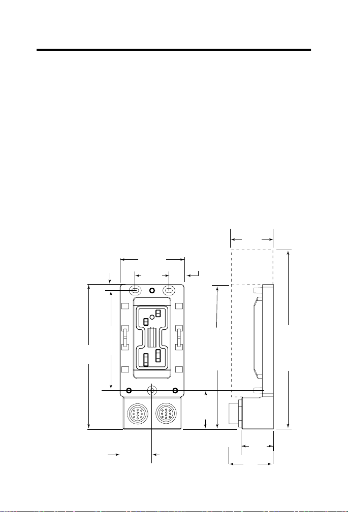
Mount the Cable Base
The cable base can be mounted either vertically or horizontally, using
3 screws. Cable bases accommodate 4 or 8 point ArmorBlock MaXum
modules. You must allow additional space for installation of 8 point
ArmorBlock MaXum module, which are longer than 4 point modules.
1792D-CB23
When
installing a
cable base
with an 8
connector
module,
allow for
the
additional
length.
6.10in
155mm
0.26in
6.5mm
4.21in
107mm
1.35in
34.25mm
2.70in
68.5mm
1.42in
36mm
0.64in
16.25mm
6.10in
155mm
4 connector
module
1.63in
41.5mm
Publication
1.90in
48.18mm
8.23in
209mm
8 connector
module
1.34in
34mm
2.27in
57.6mm
1792D-IN054B-EN-P - April 2003
43332
Page 6

6 ArmorBlock MaXum Robot I/O Cable Base and Kempf Box Plate
1. Mount the MaXum Kempf plate to the Kempf box.
MaXum Kempf plate
MaXum Kempf box
43339
2. Mount the CB23 cable base to the gasket and the Kempf box.
The mounting instructions are illustrated below.
MaXum CB23
gasket
Publication
MaXum Kempf plate
MaXum
Kempf box
31467-m
1792D-IN054B-EN-P - April 2003
Page 7

ArmorBlock MaXum Robot I/O Cable Base and Kempf Box Plate 7
!
WARNING
Attach the Module to the Base
IMPORTANT
1. Position the module over the mounted cable base. Align the
three captive screws in the module with the accepting
receptacles in the base.
2. Tighten the screws with a torque of 8 inch-pounds to secure
the module to the base.
Make sure you properly align the screws to
complete the connections between the module
contacts and the cable contacts.
If you insert or remove the module while
backplane power is on, an electrical arc can
occur. This could cause an explosion in
hazardous location installations.
Be sure that power is removed or the area is
nonhazardous before proceeding.
Screws must be
aligned properly to
complete contact
connections.
Publication
Contact
connections
1792D-IN054B-EN-P - April 2003
43335
Page 8

8 ArmorBlock MaXum Robot I/O Cable Base and Kempf Box Plate
ArmorBlock MaXum I/O modules are described in the following
publications:
• 1792D series of ArmorBlock MaXum Installation Instructions
• 1792-TD001 ArmorBlock Technical Data
The DeviceNet Network uses advanced network technology,
producer/consumer communication, to increase network
functionality and throughput. Visit our web site at
http://www.ab.com/networks
information and updates.
for producer/consumer technology
Attach the Cables
1. Attach your network cable and power cable (if used) to the
connectors.
2. Cover the power connector with a cap if it is not used.
Publication
1792D-IN054B-EN-P - April 2003
Page 9

ArmorBlock MaXum Robot I/O Cable Base and Kempf Box Plate 9
!
WARNING
3. Attach your I/O connector cables.
Female
Male
Network
In
If you connect or disconnect the DeviceNet cable
with power applied to this module or any device
on the network, an electrical arc can occur. This
could cause an explosion in hazardous location
installations.
Be sure that power is removed or the area is
nonhazardous before proceeding.
Publication
Network
Out
31463-m
1792D-IN054B-EN-P - April 2003
Page 10

10 ArmorBlock MaXum Robot I/O Cable Base and Kempf Box Plate
!
WARNING
!
WARNING
Use supply wires suitable for 30°C above
surrounding ambient.
If you connect or disconnect wiring while the
field-side power is on, an electrical arc can occur.
This can cause an explosion in hazardous location
installations. Be sure that power is removed or the
area is nonhazardous before proceeding.
Publication
1792D-IN054B-EN-P - April 2003
Page 11

ArmorBlock MaXum Robot I/O Cable Base and Kempf Box Plate 11
Use the graphics below to connect DeviceNet cable to your module.
4
2
14
5
1
17
6
12
16
Outgoing
installation
remote bus
(Male connector)
7
Assembly side
8
43478
DI
DO
~DI
~DO
COM
reserved
10
11
Red
10
11
SCM2 (~DI)
COM (Profi A)
+24V (US1)
64132
Red
Black
Green
6
4
+24V (US1)
reserved (Profi B)
Outgoing
Hybrid Cable
789
Pink
Gray
Green
Yellow
789
DO
~DO
Incoming
SCM1 (DI)
Hybrid Cable
RET (US1)
+24V (US2)
Brown
132
RET (US1)
+24V (US2)
RET (US2)
Blue
RET (US2)
CCR1
121713
Red
Blue
121713
CCR1
CCR2
CCR2
White
DeviceNet High
DeviceNet High
DeviceNet Low
14515
Blue
Green/Yellow
14515
DeviceNet Low
PE
UL
RBST
Flange
16
CCR = Constant current regulation
SCM = Secondary circuit monitoring
16
PE
Flange
reserved
reserved
8
7
6
16
17
5
12
4
14
Incoming
installation
remote bus
1
2
Assembly side
(Female connector)
Publication
1792D-IN054B-EN-P - April 2003
Page 12

12 ArmorBlock MaXum Robot I/O Cable Base and Kempf Box Plate
Specifications
Robot I/O Cable Bases - Cat. No. 1792D-CB23 & -KPLT
General Specific at ions
For general specifications, see the ArmorBlock MaXum module’s documentation
or the Technical Data, publicatio n number 1792-TD001. The specific a ti ons li sted
in these publicat ions are for the assembled module and cable base.
Publication
1792D-IN054B-EN-P - April 2003
Page 13

ArmorBlock MaXum Robot I/O Cable Base and Kempf Box Plate 13
Hazardous Location Approval
The following information applies when operating
this equipment in hazardous locations:
Products marked “CL I, DIV 2, GP A, B, C, D” are suita ble
for use in Class I Division 2 Groups A, B, C, D, Hazardo us
Locations and nonhazardou s locations only. Each product
is supplied with markings on the rating nameplate
indicating the hazardous location temperature code.
When combining products wi thin a system, the most
adverse temperature code (lo west “T” number) may be
used to help determine the over all temperature code of
the system. Combinations of equipment in your system
are subject to investigation by the local Authority Having
Jurisdiction at the time of installation.
WARNING
!
EXPLOSION HAZARD
• Do not disconnect equipment
unless power has been
removed or the area is known
to be nonhazardous.
• Do not disconnect
connections to this equipment
unless power has been
removed or the area is known
to be nonhazardous. Secure
any external connectio ns that
mate to this equipment by
using screws, sliding latches,
threaded connectors, or other
means provided with this
product.
• Substitution of components
may impair suitability for
Class I, Division 2.
• If this product contains
batteries, they must onl y be
changed in an area known to
be nonhazardous.
Informations sur l’utilisation de cet équipement en
environnements dangereux :
Les produits marqués "CL I , DIV 2, GP A, B, C, D" ne
conviennent qu’à une utilisatio n en environnements de
Classe I Division 2 Groupes A, B, C, D da ngereux et non
dangereux. Chaque produit est liv ré avec des marquages sur
sa plaque d’identification qui ind iquent le code de
température pour les environn ements dangereux. Lorsque
plusieurs produits sont combinés dans un système, le code
de température le plus défavorable (c ode de température le
plus faible) peut être utilisé pour déterm iner le code de
température global du système. Les combinaisons
d’équipements dans le système sont sujettes à inspection
par les autorités locales qualifiées au moment de
l’installation.
AVERTISSEMENT
!
RISQUE D’EXPLOSION
• Couper le courant ou
s’assurer que l’environnemen t
est classé non dangereux
avant de débrancher
l'équipement.
• Couper le courant ou
s'assurer que l’environnement
est classé non dangereux
avant de débrancher les
connecteurs. Fixer tous les
connecteurs externes rel iés à
cet équipement à l'aide de
vis, loquets coulissants ,
connecteurs filetés ou autre s
moyens fournis avec ce
produit.
• La substitution de
composants peut rendre c et
équipement inadapté à une
utilisation en environnement
de Classe I, Division 2.
• S’assurer que
l’environnement est classé
non dangereux avant de
changer les piles.
Publication
1792D-IN054B-EN-P - April 2003
Page 14

14 ArmorBlock MaXum Robot I/O Cable Base and Kempf Box Plate
This product has been tested at an Open DeviceNet Vendor
Association, Inc. (ODVA) authorized independent test laboratory and
found to comply with ODVA Conformance Test. Please contact the
ODVA website (http://www.odva.org) for listing of products tested by
ODVA independent test labs for further details.
Publication
1792D-IN054B-EN-P - April 2003
Page 15

Notes:
ArmorBlock MaXum Robot I/O Cable Base and Kempf Box Plate 15
Publication
1792D-IN054B-EN-P - April 2003
Page 16
Rockwell Automation Support
Rockwell Automation tests all of our products to ensure that they are
fully operational when shipped from the manufacturing facility.
If you are experiencing installation or startup problems, please
review the troubleshooting information contained in this publication
first. If you need technical assistance to get your module up and
running, please contact Customer Support (see the table below); our
trained technical specialists are available to help.
If the product is not functioning and needs to be returned, contact
your distributor. You must provide a Customer Support case number
to your distributor in order to complete the return process.
Phone United States/Canada 1.440.646.5800
Outside United
States/Canada
You can access the phone number for your country
via the Internet:
1. Go to http://support.rockwellautomation.com/
Contacting Customer Support
2. Under
Countries, click on
Internet Worldwide Go to http://support.rockwellautomation.com/
ArmorBlock and ArmorBlock MaXum are trademarks of Rockwell Automation.
DeviceNet is a trademark of Open DeviceNet Vendor Association (ODVA).
Click here
and Other
Publication 1792D-IN054B-EN-P - April 2003 PN 957782-47
Supersedes Pub lication 1792D-IN054A-E N-P - August 2002 Copyright © 2003 Rockw ell Automation, Inc. All r ights reserved. Print ed in the U.S.A.
 Loading...