

Page 1
Installation Instructions
ArmorBlock MaXum I/O Cable Bases
Series B
(Series 1792D-CBXXX)
41528
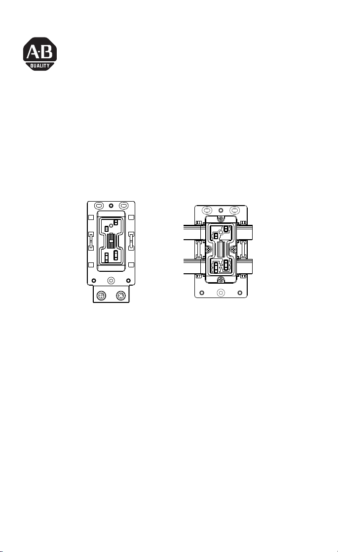
CB12
The ArmorBlock MaXum™ Ι/Ο Cable Bases mate with 4 or 8 point
modules depending on your installation requirements. No
modification is required. Modules are interchangeable whether flat or
round media cable bases are used. This interchangeability provides
plug and play block upgrade capability and easy field replacement.
The completely assembled ArmorBlock module and base requires no
enclosure.
These instructions describe the installation of each cable base. The
catalog numbers for the cable bases are:
• 1792D-CB12 for 12mm drop cable installation, see page 3
• 1792D-CBFM for flat media installation using KwikLink™
cabling, see page 7
(Please note: ArmorBlock MaXum modules and flat or round media
cables are ordered and shipped separately.)
CBFM
41529
Publication 1792D-IN009B-EN-P - September 2000
Page 2

2 ArmorBlock MaXum I/O Cable Bases Series B
European Union Directive Compliance
If this product has the CE mark it is approved for installation within
the European Union and EEA regions. It has been designed and
tested to meet the following directives.
EMC Directive
This product is tested to meet Council Directive 89/336/EEC
Electromagnetic Compatibility (EMC) and the following standards, in
whole or in part, documented in a technical construction file:
• EN 50081-2 EMC - Generic Emission Standard, Part 2 Industrial Environment
• EN 50082-2 EMC - Generic Immunity Standard, Part 2 Industrial Environment
This product is intended for use in an industrial environment.
Low Voltage Directive
This product is tested to meet Council Directive 73/23/EEC Low
Voltage, by applying the safety requirements of EN 61131-2
Programmable Controllers, Part 2 - Equipment Requirements and
Tests.
For specific information required by EN 61131-2, see the appropriate
sections in this publication, as well as the following Allen-Bradley
publications:
• Industrial Automation Wiring and Grounding Guidelines For
Noise Immunity, publication 1770-4.1
• Automation Systems Catalog, publication B113
Package Contents for 1792D-CB12
Your package contains:
• 1 ArmorBlock 12mm cable base
• installation instructions
(Please note: ArmorBlock MaXum modules are ordered and shipped
separately.)
Publication 1792D-IN009B-EN-P - September 2000
Page 3
ArmorBlock MaXum I/O Cable Bases Series B 3
Install Your ArmorBlock 1792D-CB12
To install the cable base:
• Mount the cable base
• Attach the module to the base
• Attach the cables
These steps are described in more detail in the following
sections.
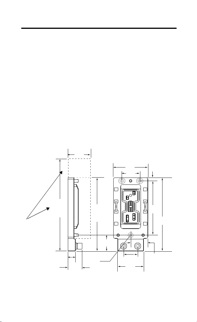
Mount the Cable Base
The cable base can be mounted either vertically or horizontally, using
3 screws. Cable bases accommodate 4 or 8 point ArmorBlock MaXum
modules. You must allow additional space for installation of 8 point
ArmorBlock MaXum modules. They are longer than the 4 point
modules.
12mm
1.90in.
48.18mm
2.70in.
68.5mm
1.42in.
36.0mm
0.26in.
6.5mm
When
installing a
cable base
with an 8
connector
module, allow
for the
additional
length.
7.84in.
199mm
7 connector
module
0.60in.
15.3mm
1.10in.
28mm
5.71in.
145mm
4 connector
pins
0.18in.
04.6mm
1.24in.
31.5mm
1.10in.
28mm
2.05in.
52mm
4.21in.
107mm
1.35in.
34.18mm
5.71in.
145mm
41537
Publication 1792D-IN009B-EN-P - September 2000
Page 4
4 ArmorBlock MaXum I/O Cable Bases Series B
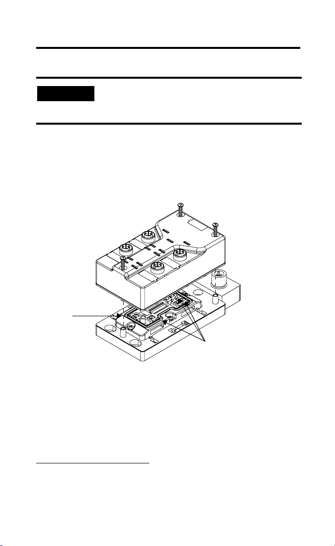
Attach the Module to the Base
IMPORTANT
Make sure you properly align the screws to
complete the connections between the module
contacts and the cable contacts.
1. Position the module over the mounted cable base. Align the
three captive screws in the module with the accepting
receptacles in the base.
2. Tighten the screws with a torque of 8 inch-pounds to secure
the module to the base.
Screws must be
aligned properly to
complete contact
connections.
Contact
connections
30834-M
ArmorBlock MaXum I/O modules are described in the following
publications:
• 1792D series of ArmorBlock MaXum Installation Instructions
• 1792-TD001B-EN-P ArmorBlock Technical Data
The DeviceNet™ Network uses advanced network technology,
producer/consumer communication, to increase network
functionality and throughput. Visit our web site at
http://www.ab.com/networks
for producer/consumer technology
information and updates.
Publication 1792D-IN009B-EN-P - September 2000
Page 5
ArmorBlock MaXum I/O Cable Bases Series B 5
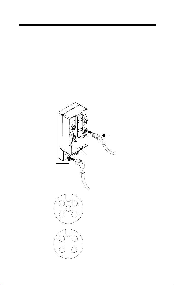
Attach the Cables
1. Attach your network cable and power cable (if used) to the
connectors.
Note: The network and power cables drop straight down
away from the module.
2. Cover the power connector with a micro cap if it is not used.
3. Attach your point connector cables.
Note: Point connector cables drop at a 45 degree angle
because of the pin settings, if you use a right angle connector.
4. Cover any unused point connectors with micro caps.
Point connector cable with a right
angle connector
5 pin network
connector
DeviceNet Male Connector
2
5
34
Auxiliary Output Male Connector
2
34
4 pin output power
connector
Pin 1 Drain
1
1
Pin 2 V+
Pin 3 VPin 4 CAN_H
Pin 5 CAN_L
Pin 1 24Vdc
Pin 2 24Vdc
Pin 3 Return
Pin 4 Return
Publication 1792D-IN009B-EN-P - September 2000
30838
41583
41584
Page 6

6 ArmorBlock MaXum I/O Cable Bases Series B
Package Contents for 1792D-CBFM
Your package contains:
• 1 ArmorBlock cable base
• 1 seal block with hardware
• 2 end caps
• installation instructions
(Please note: Modules are ordered and shipped separately.)
Install Your ArmorBlock MaXum 1792D-CBFM
To install the cable base:
• Mount the cable base
• Prepare the flat media cables
• Attach the flat media cables
• Attach the seal block
• Attach the module to the base
These steps are described in more detail in the following
sections.
Publication 1792D-IN009B-EN-P - September 2000
Page 7

ArmorBlock MaXum I/O Cable Bases Series B 7
Mount the Cable Base
The cable base can be mounted either vertically or horizontally.
Cable bases accommodate either 4 or 8 point ArmorBlock MaXum
modules. Additional space allowances must be made for 8 point
ArmorBlock MaXum modules.
When
installing a
cable base
with an 8
point module,
allow for the
additional
length.
6.85in.
174mm 8
connector
module
4.72in.
120mm
4.72in.
120mm
4 connector
module
2.70in.
68.5mm
1.42in.
36mm
0.64in.
16.25mm
4.21in.
107mm
4.72in.
120mm
Flat Media
0.18in.
04.6mm
1.35in.
34.25mm
0.26in.
6.5mm
41536
Some network installations may subject the cables to a great deal of
flexing. In this case, we recommend clamping the flat media cable at
a specific distance from the base. Refer to the DN-6.7.2 publication
for more information.
Prepare the Flat Media Cables
The 1792D-CBFM cable base using a KwikLink flat media system
accommodates the following cable routings while maintaining full
IP67 sealing integrity. Determine if your network system will pass
through or end at this cable base. These options are available:
• DeviceNet and Auxiliary Power cables both pass through the
base
• DeviceNet cable only passes through the base
• DeviceNet passes through and Auxiliary Power ends at this
base
• Both DeviceNet and Auxiliary Power end at this base
Publication 1792D-IN009B-EN-P - September 2000
Page 8

8 ArmorBlock MaXum I/O Cable Bases Series B
IMPORTANT
You must apply end caps to cables that end at the
base prior to installation. The caps seal the cables.
The cable, with the end cap applied, must end
between the two lines on the cable base as shown
below. When Auxiliary Power is not used, seal
both openings to the power slot. See specific
instructions on page 10.
The cable, with the end cap applied, must end between the two lines
on the cable base, as shown below.
Pass through
End cap
The cable must end between these two lines. The clear end cap
allows you to see the cable position.
Apply End cap
prior to installing
cable.
If a power cable is not
used, seal the cable
slots. Place the two
end caps in the slots
to seal them.
30827-M
Publication 1792D-IN009B-EN-P - September 2000
Page 9

ArmorBlock MaXum I/O Cable Bases Series B 9
Attach the Flat Media Cables
The KwikLink DeviceNet flat media cable is a four-conductor cable. It
has a key design feature that allows it to “seat” in the cable base in
only one direction. Labels indicate which slot to use for the Auxiliary
Power and DeviceNet connection.
To attach the flat media cable use the steps listed in the following
graphic.
3. Align the keying features of
1. Remove the end cap
covers from the storage
area. These are used to
cover the cables when they
end.
End cap storage
(2 caps are provided)
2. Apply an end cap to cables
that end at this point in your
network. End caps cannot be
applied after the cables are
attached to the base.
POWER and NETWORK labels indicate Auxiliary
Power and DeviceNet cable placement.
POWER
NETWORK
the cable and base. The cable
and cable slots are angled. The
cables can only be placed in one
direction.
4. Modules with outputs require
an Auxiliary Power cable. If the
module you use has outputs,
snap the black power cable into
the slot labeled POWER.
5. Snap the gray DeviceNet
cable into the slot labeled
NETWORK.
30829-M
41530
Publication 1792D-IN009B-EN-P - September 2000
Page 10

10 ArmorBlock MaXum I/O Cable Bases Series B
Attach the Seal Block
The seal block has piercing contacts. Contact occurs when you attach
the seal block to the cable base. The seal block is designed to attach
to the base in only one direction.
ATTENTION
!
Avoid injury. Piercing
contacts are
extremely sharp.
To install the seal block:
• The seal block has extremely sharp piercing
contacts. Do not press against them with
your fingers. You may be injured.
• You must properly align the seal block when
you attach it to the base. This will maintain
the integrity of the sealed base. You can only
pierce the cable once. Once pierced, the seal
block must not be removed. This will ensure
the inner conductors are not exposed by
pulling out the piercing contacts.
Only one attempt to pierce the cable is allowed.
41534
1. Position the seal block over the cable base.
a. Match the arrows on the bottom of the base and seal block.
b. Align the four captive screws in the seal block with the
accepting receptacles in the base.
2. Tighten the screws with a torque of 8 to10 inch-pounds to
secure the module to the base. To assure even piercing,
tighten each screw a little at a time.
.
Publication 1792D-IN009B-EN-P - September 2000
Page 11

ArmorBlock MaXum I/O Cable Bases Series B 11
IMPORTANT
When the lines
of the seal block
meet the base it
is fully seated.
ATTENTION
!
There are 3 seating lines on the sides of the seal
block, under the captive screws. As the screws are
tightened these lines meet the cable base. At this
point the seal block is fully seated.
Seal
Block
Match arrows so
the seal block is
in the correct
position over the
cable base.
Base
41533
Make sure all screws and end caps are securely
tightened to properly seal the base against leaks
and maintain IP67 requirements.
Attach the Module to the Base
IMPORTANT
1. Position the module over the mounted cable base. Align the
three captive screws in the module with the accepting
receptacles in the base.
Make sure you properly align the screws to
complete the connections between the module
contacts and the cable contacts.
Publication 1792D-IN009B-EN-P - September 2000
Page 12

12 ArmorBlock MaXum I/O Cable Bases Series B
2. Tighten the screws with a torque of 8 inch-pounds to secure
the module to the base.
30704-M
ArmorBlock MaXum I/O modules are described in the following
publications:
• 1792D series of ArmorBlock MaXum Installation Instructions
• 1792-TD001B-EN-P - ArmorBlock Technical Data
Specifications
I/O Cable Bases - Cat. No. 1792D-CBXXX
General Specifications
For general specifications, see the ArmorBlock MaXum module’s documentation or the
Technical Data, 1792-TD001B-EN-P. The specifications listed in these publications are for
the assembled module and cable base.
Publication 1792D-IN009B-EN-P - September 2000
Page 13

ArmorBlock MaXum I/O Cable Bases Series B 13
Hazardous Location Approval
The following information applies only to products marked
with Hazardous Location Approval, when operating in
hazardous locations:
Products marked “CL I, DIV 2, GP A, B, C, D” are suitable for use in
Class I Division 2 Groups A, B, C, D, Hazardous Locations and
nonhazardous locations only. Each product is supplied with markings
on the rating nameplate indicating the hazardous location
temperature code. When combining products within a system, the
most adverse temperature code (lowest “T” number) may be used to
help determine the overall temperature code of the system.
Combinations of equipment in your system are subject to
investigation by the local Authority Having Jurisdiction at the time of
installation.
WARNING
!
WARNING
!
EXPLOSION HAZARD -
• Do not disconnect equipment unless power
has been removed or the area is known to be
nonhazardous.
• Do not disconnect connections to this
equipment unless power has been removed
or the area is known to be nonhazardous.
Secure any external connections that mate to
this equipment by using screws, sliding
latches, threaded connectors, or other means
provided with this product.
• Substitution of components may impair
suitability for Class I, Division 2.
• If this product contains batteries, they must
only be changed in an area known to be
nonhazardous.
Use supply wires suitable for 30°C above
surrounding ambient.
Publication 1792D-IN009B-EN-P - September 2000
Page 14

14 ArmorBlock MaXum I/O Cable Bases Series B
WARNING
When used in a Class I, Division 2, hazardous
location, this equipment must be mounted in a
suitable enclosure with proper wiring method that
complies with the governing electrical codes.
!
Les informations suivantes ne concernent que les produits
marqués pour une utilisation en environnements dangereux :
Les produits marqués « CL I, DIV 2, GP A, B, C, D » ne conviennent
qu’à une utilisation en environnements de Classe I Division 2
Groupes A, B, C, D dangereux et non dangereux. Chaque produit est
livré avec des marquages sur sa plaque d’identification qui indiquent
le code de température pour les environnements dangereux. Lorsque
plusieurs produits sont combinés dans un système, le code de
température le plus défavorable (code de température le plus faible)
peut être utilisé pour déterminer le code de température global du
système. Les combinaisons d’équipements dans le système sont
sujettes à inspection par les autorités locales qualifiées au moment de
l’installation.
AVERTISSEMENT
!
RISQUE D’EXPLOSION -
• Couper le courant ou s’assurer que
l’environnement est classé non dangereux
avant de débrancher l’équipement.
• Couper le courant ou s’assurer que
l’environnement est classé non dangereux
avant de débrancher les connecteurs. Fixer
tous les connecteurs externes reliés à cet
équipement à l’aide de vis, loquets
coulissants, connecteurs filetés ou autres
moyens fournis avec ce produit.
• La substitution de composants peut rendre cet
équipement inadapté à une utilisation en
environnement de Classe I, Division 2.
• S’assurer que l’environnement est classé non
dangereux avant de changer les piles.
Publication 1792D-IN009B-EN-P - September 2000
Page 15

ArmorBlock MaXum I/O Cable Bases Series B 15
AVERTISSEMENT
Utiliser des fils d’alimentation qui conviennent à
une température de 30°C au-dessus de la
température ambiante.
!
AVERTISSEMENT
Pour une utilisation en environnement de classe i,
division 2 dangereux, cet equipement doit etre
monte dans un boitier avec un cablage approprie
conforme aux normes electriques en vigueur.
!
This product has been tested at an Open DeviceNet
Vendor Association, Inc. (ODVA) authorized
independent test laboratory and found to comply with
ODVA Conformance Test. Please contact the ODVA
website (http://www.odva.org) for listing of products
tested by ODVA independent test labs for further details
.
Publication 1792D-IN009B-EN-P - September 2000
Page 16

ArmorBlock, ArmorBlock MaXum and KwikLink are trademarks of Rockwell Automation.
DeviceNet is a trademark of Open DeviceNet Vendor Association (ODVA).
Publication 1792D-IN009B-EN-P - September 2000 PN 957395-71
Supersedes Publication 1792D-5.9 - Nov ember 1998 © 2000 Rockwell Internati onal Corporation. Printed in USA
 Loading...