

Page 1
Installation Instructions
ArmorBlock MaXum I/O Cable Bases
Series B
(Cat. No. 1792D-CB18, -CB18P, -CB18PT)
CB18
41712
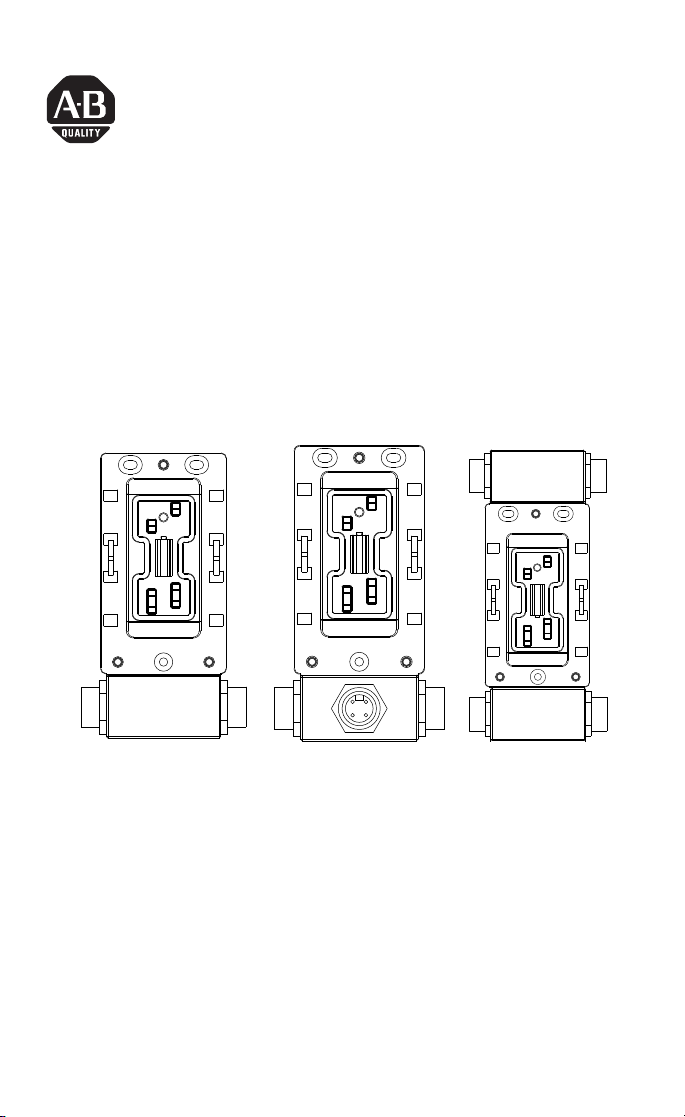
The 18mm ArmorBlock MaXum™ Ι/Ο Cable Bases mate with 4 or 8
point modules depending on your installation requirements. No
modification is required. Modules are interchangeable whether flat or
round media cable bases are used. This interchangeability provides
plug and play block upgrade capability and easy field replacement.
The completely assembled ArmorBlock module and base requires no
enclosure.
CB18P CB18PT
41713
41714
Publication 1792D-IN036B-EN-P - September 2000
Page 2

2 ArmorBlock MaXum I/O Cable Bases Series B
These instructions describe the installation of each cable base. The
catalog numbers for the cable bases are:
• 1792D-CB18 for 18mm trunk or drop cable installation
• 1792D-CB18P, -CB18PT for 18mm trunk or drop cable
installation when an auxiliary output power connection is
necessary
IMPORTANT
ArmorBlock MaXum modules and media cables are
ordered and shipped separately.
Install Your ArmorBlock Cable Base
To install the cable base:
• Mount the cable base
• Attach the module to the base
• Attach the cables
These procedures are explained in detail in the following sections.
Publication 1792D-IN036B-EN-P - September 2000
Page 3
ArmorBlock MaXum I/O Cable Bases Series B 3
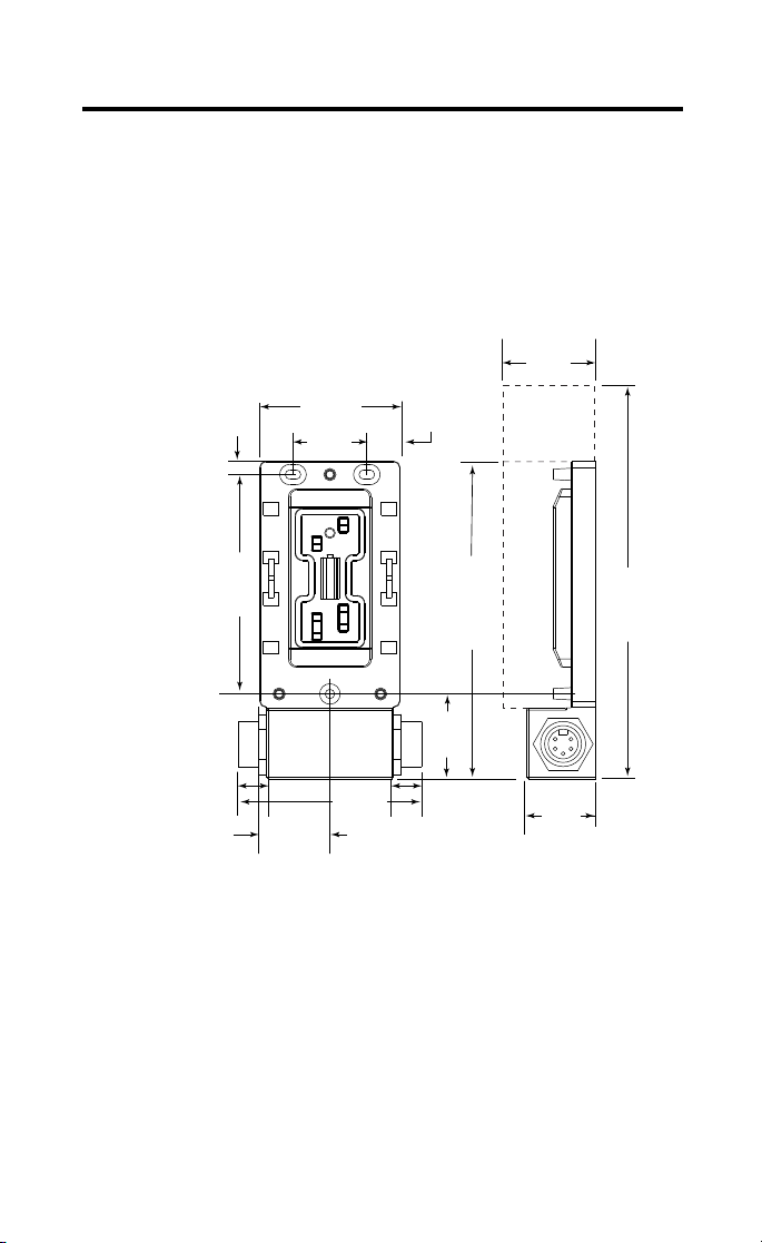
Mount the Cable Base
The cable base can be mounted either vertically or horizontally, using
3 screws. Cable bases accommodate 4 or 8 point ArmorBlock MaXum
modules. You must allow additional space for installation of 8 point
ArmorBlock MaXum modules. They are longer than the 4 point
modules.
1792D-CB18
When
installing a
cable base
with an 8
connector
module, allow
for the
additional
length.
0.26in
6.5mm
4.21in
107mm
.764in
19.4mm
1.35in
34.25mm
2.70in
68.5mm
1.42in
36mm
4.00in
101.5mm
0.64in
16.25mm
155mm
4 connector
module
1.63in
41.5mm
.791in
20.1mm
6.10in
1.90in
48.18mm
1.34in
34mm
8.23in
209mm
8 connector
module
30798
Publication 1792D-IN036B-EN-P - September 2000
Page 4
4 ArmorBlock MaXum I/O Cable Bases Series B
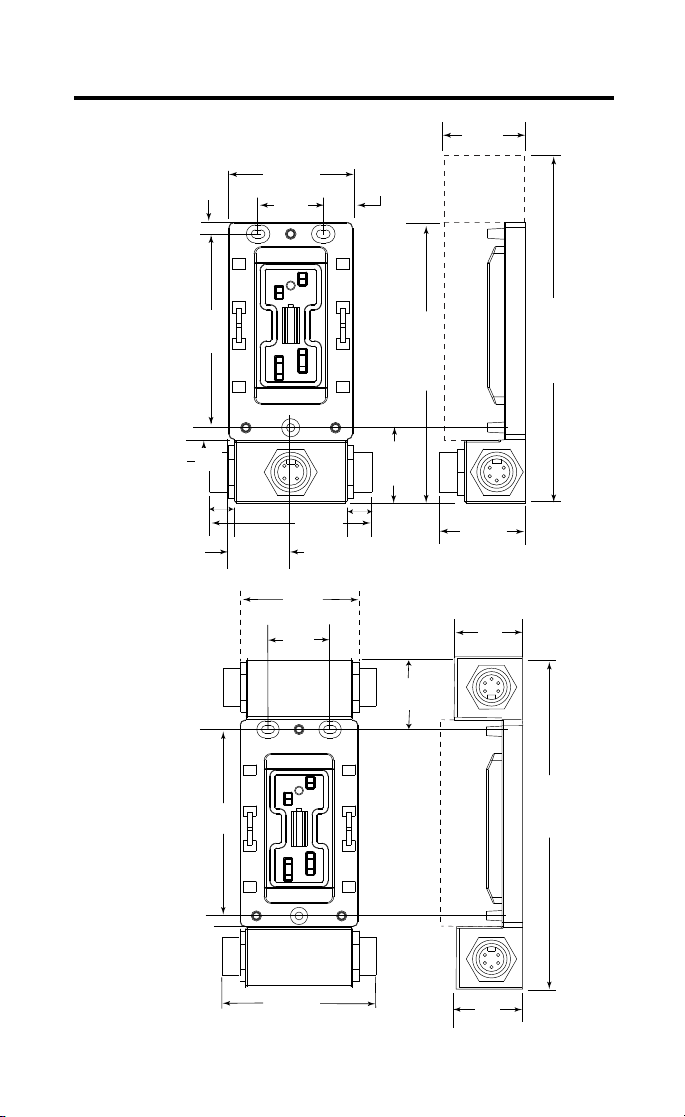
1792D-CB18P
When
installing a
cable base
with an 8
connector
module,
allow for
the
additional
length.
1792D-CB18PT
0.26in
6.5mm
107mm
.764in
19.4mm
4.21in
1.35in
34.25mm
2.70in
68.5mm
1.42in
36mm
2.70in
68.5mm
1.42in
36mm
4.00in
101.5mm
0.64in
16.25mm
6.10in
155mm
4 connector
module
1.63in
41.5mm
.791in
20.1mm
1.61in
41mm
1.90in
48.18mm
2.130in
54.1mm
1.34in
34mm
8.23in
209mm
8 connector
module
41696
This base
accommodates
only 4
connector
4.21in
107mm
modules.
4.00in
101.5mm
Publication 1792D-IN036B-EN-P - September 2000
1.90in
48.18mm
7.46in
189.5mm
41623
Page 5

Attach the Module
ArmorBlock MaXum I/O Cable Bases Series B 5
IMPORTANT
Make sure you properly align the screws to complete
the connections between the module contacts and the
cable contacts.
1. Position the module over the mounted cable base. Align the
three captive screws in the module with the accepting
receptacles in the base.
2. Tighten the screws with a torque of 8 inch-pounds to secure
the module to the base.
Screws must be
aligned properly to
complete contact
connections.
Contact
connections
41715
ArmorBlock MaXum I/O modules are described in the following
publications:
• 1792D series of ArmorBlock MaXum Installation Instructions
• 1792-TD001B-EN-P ArmorBlock Technical Data
The DeviceNet Network uses advanced network technology,
producer/consumer communication, to increase network
functionality and throughput. Visit our web site at
http://www.ab.com/networks
for producer/consumer technology
information and updates.
Publication 1792D-IN036B-EN-P - September 2000
Page 6

6 ArmorBlock MaXum I/O Cable Bases Series B
Attach the Cables
1. Attach your network cable and power cable (if used) to the
connectors.
2. Cover the power connector with a cap if it is not used.
3. Attach your point connector cables.
1792D-CB18
Point connector cable with a
right angle connector
5 pin DeviceNet
In connector
Point connector cable with a
right angle connector
5 pin DeviceNet
In connector
4 pin auxiliary output
power In connector
Point connector cable with a
right angle connector
5 pin DeviceNet
In connector
1792D-CB18P
4 pin auxiliary output power in with a
right angle connector
1792D-CB18PT
5 pin DeviceNet
Out connector
5 pin DeviceNet
Out connector
41876
5 pin DeviceNet
Out connector
41716
4 pin auxiliary output
power Out connector
41877
Publication 1792D-IN036B-EN-P - September 2000
Page 7

ArmorBlock MaXum I/O Cable Bases Series B 7
Use the graphics below to connect DeviceNet cable to your module.
DeviceNet In Connector (looking
into pins)
DeviceNet Out Connector (looking
into sockets)
1
2
Auxiliary Output Power In Connector
5
4
3
(looking into pins)
1
3
4
2
Pin 1 Drain
Pin 2 V+
Pin 3 VPin 4 CAN_H
Pin 5 CAN_L
Pin 1 24Vdc
Pin 2 Not Used
Pin 3 Not Used
Pin 4 Return
5
4
Auxiliary Output Power In Connector
(looking into sockets)
1
2
3
1
3
4
2
41878
Specifications
I/O Cable Bases - Cat. No. 1792D-CB18, -18P, -18PT
General Specifications
For general specifications, see the ArmorBlock MaXum module’s documentation or the
Technical Data, publication number 1792-TD001B-EN-P. The specifications listed in
these publications are for the assembled module and cable base.
Publication 1792D-IN036B-EN-P - September 2000
Page 8

8 ArmorBlock MaXum I/O Cable Bases Series B
Hazardous Location Approval
The following information applies only to products marked
with Hazardous Location Approval, when operating in
hazardous locations:
Products marked “CL I, DIV 2, GP A, B, C, D” are suitable for use in
Class I Division 2 Groups A, B, C, D, Hazardous Locations and
nonhazardous locations only. Each product is supplied with markings
on the rating nameplate indicating the hazardous location
temperature code. When combining products within a system, the
most adverse temperature code (lowest “T” number) may be used to
help determine the overall temperature code of the system.
Combinations of equipment in your system are subject to
investigation by the local Authority Having Jurisdiction at the time of
installation.
WARNING
!
WARNING
EXPLOSION HAZARD -
• Do not disconnect equipment unless power
has been removed or the area is known to be
nonhazardous.
• Do not disconnect connections to this
equipment unless power has been removed
or the area is known to be nonhazardous.
Secure any external connections that mate to
this equipment by using screws, sliding
latches, threaded connectors, or other means
provided with this product.
• Substitution of components may impair
suitability for Class I, Division 2.
• If this product contains batteries, they must
only be changed in an area known to be
nonhazardous.
Use supply wires suitable for 30°C above
surrounding ambient.
!
Publication 1792D-IN036B-EN-P - September 2000
Page 9

ArmorBlock MaXum I/O Cable Bases Series B 9
WARNING
When used in a Class I, Division 2, hazardous
location, this equipment must be mounted in a
suitable enclosure with proper wiring method that
complies with the governing electrical codes.
!
Les informations suivantes ne concernent que les produits
marqués pour une utilisation en environnements dangereux :
Les produits marqués « CL I, DIV 2, GP A, B, C, D » ne conviennent
qu’à une utilisation en environnements de Classe I Division 2
Groupes A, B, C, D dangereux et non dangereux. Chaque produit est
livré avec des marquages sur sa plaque d’identification qui indiquent
le code de température pour les environnements dangereux. Lorsque
plusieurs produits sont combinés dans un système, le code de
température le plus défavorable (code de température le plus faible)
peut être utilisé pour déterminer le code de température global du
système. Les combinaisons d’équipements dans le système sont
sujettes à inspection par les autorités locales qualifiées au moment de
l’installation.
AVERTISSEMENT
!
RISQUE D’EXPLOSION -
• Couper le courant ou s’assurer que
l’environnement est classé non dangereux
avant de débrancher l’équipement.
• Couper le courant ou s’assurer que
l’environnement est classé non dangereux
avant de débrancher les connecteurs. Fixer
tous les connecteurs externes reliés à cet
équipement à l’aide de vis, loquets
coulissants, connecteurs filetés ou autres
moyens fournis avec ce produit.
• La substitution de composants peut rendre cet
équipement inadapté à une utilisation en
environnement de Classe I, Division 2.
• S’assurer que l’environnement est classé non
dangereux avant de changer les piles.
Publication 1792D-IN036B-EN-P - September 2000
Page 10

10 ArmorBlock MaXum I/O Cable Bases Series B
AVERTISSEMENT
!
AVERTISSEMENT
!
Utiliser des fils d’alimentation qui conviennent à
une température de 30°C au-dessus de la
température ambiante.
Pour une utilisation en environnement de classe i,
division 2 dangereux, cet equipement doit etre
monte dans un boitier avec un cablage approprie
conforme aux normes electriques en vigueur.
Publication 1792D-IN036B-EN-P - September 2000
Page 11

ArmorBlock MaXum I/O Cable Bases Series B 11
This product has been tested at an Open DeviceNet Vendor
Association, Inc. (ODVA) authorized independent test laboratory and
found to comply with ODVA Conformance Test. Please contact the
ODVA website (http://www.odva.org) for listing of products tested by
ODVA independent test labs for further details.
Publication 1792D-IN036B-EN-P - September 2000
Page 12

ArmorBlock and ArmorBlock MaXum are trademarks of Rockwell Automation.
DeviceNet is a trademark of Open DeviceNet Vendor Association (ODVA).
Publication 1792D-IN036B-EN-P - September 2000 PN 957395-96
Supersedes Publication 1792D-5.36 - April 1999 © 2000 Rockwell International Corporation. Printed in USA
 Loading...