

Page 1
Installation Instructions
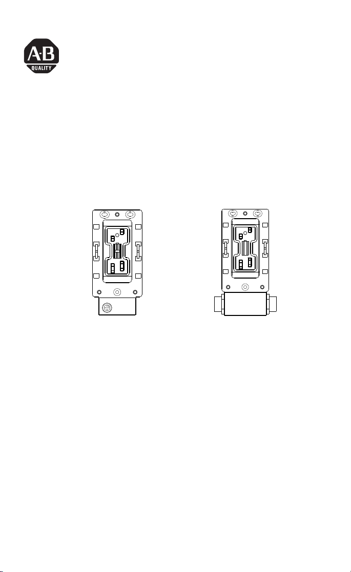
ArmorBlock MaXum I/O Cable Bases
DeviceNet Powered Outputs Series B
(Cat. No. 1792D-CB12JP and -CB18JP)
JP
CB18JP
This version of the ArmorBlock MaXum™ cable base lets you provide
power to outputs using DeviceNet™ power. No additional auxiliary
power cabling is needed. The ArmorBlock MaXum Ι/Ο cable bases
mate with 4 or 8 connector modules, depending on your installation
requirements. No modification is required. Modules are
interchangeable with round media cable bases. This
interchangeability provides plug and play block upgrade capability
and easy field replacement. The completely assembled ArmorBlock
module and base requires no enclosure.
These instructions describe the installation of each cable base. The
catalog numbers for the cable bases are:
• 1792D-CB12JP for 12mm drop cable installation, see page 5
• 1792D-CB18JP for 18mm trunk or drop cable installation, see
page 6
Publication 1792D-IN001B-EN-P - September 2000
42273CB12JP
Page 2

2 ArmorBlock MaXum I/O Cable Bases DeviceNet Powered Outputs Series B
(Please note: ArmorBlock MaXum modules and flat or round media
cables are ordered and shipped separately.)
European Union Directive Compliance
If this product has the CE mark it is approved for installation within
the European Union and EEA regions. It has been designed and
tested to meet the following directives.
EMC Directive
This product is tested to meet Council Directive 89/336/EEC
Electromagnetic Compatibility (EMC) and the following standards, in
whole or in part, documented in a technical construction file:
• EN 50081-2 EMC - Generic Emission Standard, Part 2 Industrial Environment
• EN 50082-2 EMC - Generic Immunity Standard, Part 2 Industrial Environment
This product is intended for use in an industrial environment.
Low Voltage Directive
This product is tested to meet Council Directive 73/23/EEC Low
Voltage, by applying the safety requirements of EN 61131-2
Programmable Controllers, Part 2 - Equipment Requirements and
Tests.
For specific information required by EN 61131-2, see the appropriate
sections in this publication, as well as the following Allen-Bradley
publications:
• Industrial Automation Wiring and Grounding Guidelines For
Noise Immunity, publication 1770-4.1
• Automation Systems Catalog, publication B113 Powering
Outputs Using DeviceNet Power
Publication 1792D-IN001B-EN-P - September 2000
Page 3
ArmorBlock MaXum I/O Cable Bases DeviceNet Powered Outputs Series B 3
Powering Outputs Using DeviceNet Power
You can power some output devices from the DeviceNet network.
The application must allow the voltage to remain within the
DeviceNet specification limits of 11-25V dc. Most actuators need to be
powered by a separate power supply. They usually require more
power than is practically available from DeviceNet. Also, the large
voltage variation of 11-25V that DeviceNet allows is typically beyond
the range over which most available actuators or output devices can
safely operate.
You can use DeviceNet power to operate output devices such as
hydraulic and pneumatic solenoid valves, pilot and stack lights, and
motor starter coils with the following caution:
ATTENTION
!
Do not let DeviceNet voltage at the relevant
node exceed the output device’s acceptable
voltage range. Output devices rated 24V dc
rarely are specified to operate below 19.2V dc or
-20% of their 24V dc rating. Many only operate
down to 20.4V dc or -15% of the rated voltage.
This means that the DeviceNet network design
must not let the available voltage drop below
19.2 volts, for example, instead of the 11 volts
that the DeviceNet specification allows. This
higher lower voltage limit, which is within the
DeviceNet specification, will actually restrict the
distance of the DeviceNet network from what
would be possible if actuators were not utilizing
the DeviceNet power.
IMPORTANT
Design your network so that sufficient voltage is
available to operate the output device wherever it
is installed. This is especially important when it is
connected at the farthest location from the power
supply.
Publication 1792D-IN001B-EN-P - September 2000
Page 4
4 ArmorBlock MaXum I/O Cable Bases DeviceNet Powered Outputs Series B
Noise or Transient Protection
The typical actuators used in DeviceNet control systems utilize
inductive coils that generate transients when de-energized. Each
ArmorBlock MaXum output contains a diode which is across the load
device coil. As a precaution, also use an MOV varistor suppressor at
the 24V dc coil.
ATTENTION
Do not use DeviceNet power on dc coil
actuators that use economizing coils to operate.
They have high inrush currents.
!
Package Contents for Cable Bases
Your package contains these installation instructions and the
following contents, depending on the base used:
1792D-CB12JP 1792D-CB18JP
one ArmorBlock 12mm cable base one ArmorBlock 18mm cable base
one 12mm protective cap two 18mm protective caps
(Please note: ArmorBlock MaXum modules are ordered and shipped
separately.)
Install Your ArmorBlock MaXum Cable Bases
To install the 1792-CB12JP and -CB18JP cable bases:
• Mount the cable base
• Attach the module to the base
• Attach the cables
These steps are discussed in the following procedures.
Publication 1792D-IN001B-EN-P - September 2000
Page 5
ArmorBlock MaXum I/O Cable Bases DeviceNet Powered Outputs Series B 5
4
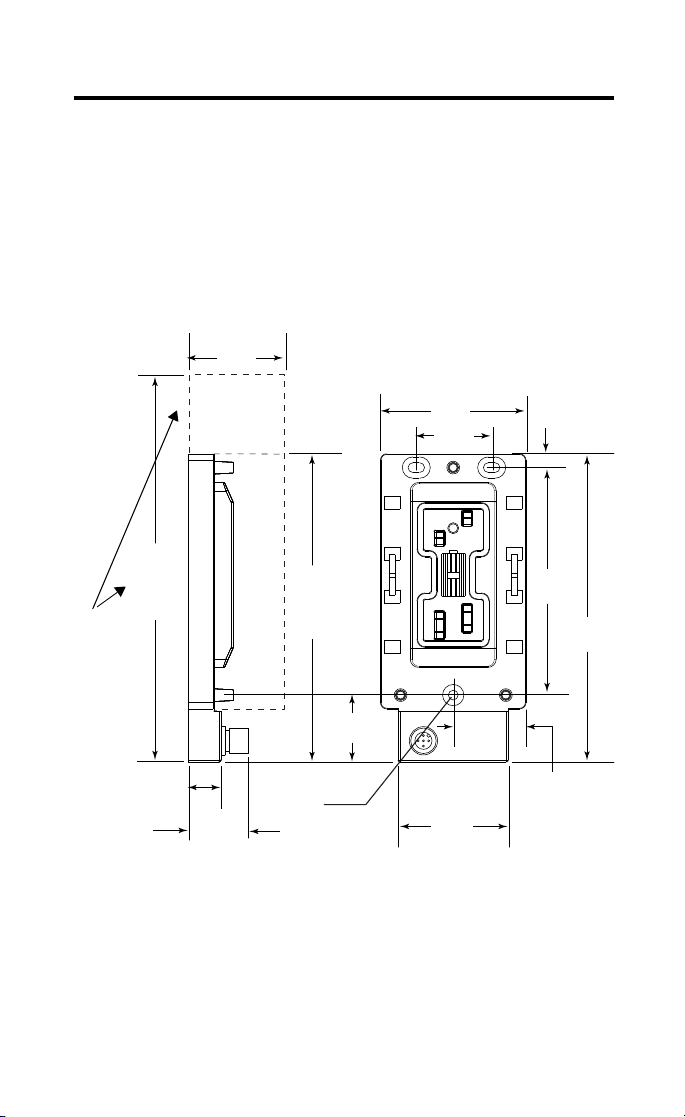
Mount the Cable Base
The cable base can be mounted either vertically or horizontally, using
3 screws. Cable bases accommodate 4 or 8 connector ArmorBlock
MaXum modules. You must allow additional space for installation of
8 connector ArmorBlock MaXum modules. They are longer than the 4
connector modules.
A mounting illustration for the 1792D-CB12JP is below.
1792D-CB12JP
1.90in.
48.18mm
When
installing a
cable base
with an 8
connector
module,
allow for
the
additional
length.
12mm
7.84in.
199mm
8 connector
module
0.60in.
15.3mm
1.10in.
28mm
5.71in.
145mm
4 connector
module
0.18in.
4.6mm
1.24in.
31.5mm
2.70in.
68.5mm
1.42in.
36mm
2.05in.
52mm
0.26in.
6.5mm
4.21in.
107mm
1.35in.
34.25mm
5.71in.
145mm
4227
Publication 1792D-IN001B-EN-P - September 2000
Page 6

6 ArmorBlock MaXum I/O Cable Bases DeviceNet Powered Outputs Series B
A mounting illustration for the 1792D-CB18JP is below.
1792D-CB18JP
0.26in.
6.5mm
4.21in.
107mm
When
installing a
cable base
with an 8
connector
module,
allow for
the
additional
length.
0.764in.
19.4mm
1.35in.
34.25mm
2.70in.
68.5mm
1.42in.
36mm
4.00in.
101.5mm
0.64in.
16.25mm
0.791in.
20.1mm
18mm
1.63in.
41.5mm
6.10in
155mm
4 connector
module
1.90in.
48.18mm
1.34in.
34mm
8.23in.
209mm
8 connector
module
42275
Publication 1792D-IN001B-EN-P - September 2000
Page 7

ArmorBlock MaXum I/O Cable Bases DeviceNet Powered Outputs Series B 7
Attach the Module
IMPORTANT
Make sure you properly align the screws to
complete the connections between the module
contacts and the cable contacts cafeteria.
1. Position the module over the mounted cable base. Align the
three captive screws in the module with the accepting
receptacles in the base.
2. Tighten the screws with a torque of 8 inch-pounds to secure
the module to the base.
The 1792D-CB12JP module is shown below.
Screws must be aligned
properly to complete
contact connections.
Contact
connections
30834-M
Publication 1792D-IN001B-EN-P - September 2000
Page 8

8 ArmorBlock MaXum I/O Cable Bases DeviceNet Powered Outputs Series B
The 1792D-CB18JP module is shown below.
JP
Screws must be a ligned
properly to complete
contact connections.
Contact
connections
42276
ArmorBlock MaXum I/O modules are described in the following
publications:
• 1792D series of ArmorBlock MaXum Installation Instructions
• 1792-TD001B-EN-P - ArmorBlock Technical Data
The DeviceNet Network uses advanced network technology,
producer/consumer communication, to increase network
functionality and throughput. Visit our web site at
http://www.ab.com/networks
information and updates.
for producer/consumer technology
Publication 1792D-IN001B-EN-P - September 2000
Page 9

ArmorBlock MaXum I/O Cable Bases DeviceNet Powered Outputs Series B 9
Attach the Cables (1792D-CB12JP)
1. Attach your network cable to the connector.
Note: The network cable drops straight down away from the
module.
2. Attach your I/O cables.
Note: I/O cables drop at a 45 degree angle because of the pin
settings, if you use a right angle connector.
3. Cover any unused point connectors with micro caps.
I/O cable with a right angle
connector
5 pin
network
connector
DeviceNet Male Connector
42278
Pin 1 Drain
Pin 2 V+
Pin 3 VPin 4 CAN_H
Pin 5 CAN_L
41583
Publication 1792D-IN001B-EN-P - September 2000
Page 10
10 ArmorBlock MaXum I/O Cable Bases DeviceNet Powered Outputs Series B
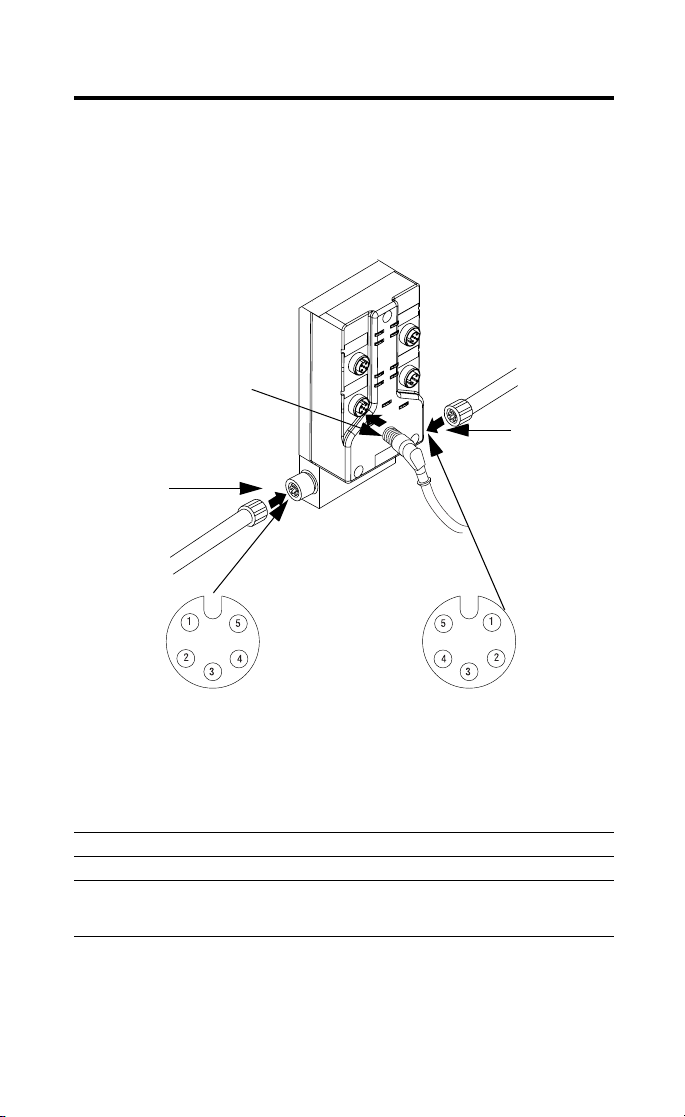
Attach the Cables (1792D-CB18JP)
1. Attach your network cables to the connectors.
2. Attach your I/O cables.
I/O cable with a right angle
connector
5 pin DeviceNet
Out connector
5 pin DeviceNet
In connector
41876
Pin 1 Drain
Pin 2 V+
Pin 3 VPin 4 CAN_H
DeviceNet In (pins)
Pin 5 CAN_L
DeviceNet Out (sockets)
41878
Specifications
ArmorBlock MaXum I/O Cable Bases - Cat. No. 1792D-CB12JP and -CB18JP
General Specifications
For general specifications, see the ArmorBlock MaXum module’s documentation or the
Technical Data, 1792-TD001B-EN-P. The specifications listed in these publications are for
the assembled module and cable base.
Publication 1792D-IN001B-EN-P - September 2000
Page 11

ArmorBlock MaXum I/O Cable Bases DeviceNet Powered Outputs Series B 11
Hazardous Location Approval
The following information applies only to products marked
with Hazardous Location Approval, when operating in
hazardous locations:
Products marked “CL I, DIV 2, GP A, B, C, D” are suitable for use in
Class I Division 2 Groups A, B, C, D, Hazardous Locations and
nonhazardous locations only. Each product is supplied with markings
on the rating nameplate indicating the hazardous location
temperature code. When combining products within a system, the
most adverse temperature code (lowest “T” number) may be used to
help determine the overall temperature code of the system.
Combinations of equipment in your system are subject to
investigation by the local Authority Having Jurisdiction at the time of
installation.
WARNING
!
WARNING
!
EXPLOSION HAZARD -
• Do not disconnect equipment unless power
has been removed or the area is known to be
nonhazardous.
• Do not disconnect connections to this
equipment unless power has been removed
or the area is known to be nonhazardous.
Secure any external connections that mate to
this equipment by using screws, sliding
latches, threaded connectors, or other means
provided with this product.
• Substitution of components may impair
suitability for Class I, Division 2.
• If this product contains batteries, they must
only be changed in an area known to be
nonhazardous.
Use supply wires suitable for 30°C above
surrounding ambient.
Publication 1792D-IN001B-EN-P - September 2000
Page 12

12 ArmorBlock MaXum I/O Cable Bases DeviceNet Powered Outputs Series B
WARNING
When used in a Class I, Division 2, hazardous
location, this equipment must be mounted in a
suitable enclosure with proper wiring method that
complies with the governing electrical codes.
!
Les informations suivantes ne concernent que les produits
marqués pour une utilisation en environnements dangereux :
Les produits marqués « CL I, DIV 2, GP A, B, C, D » ne conviennent
qu’à une utilisation en environnements de Classe I Division 2
Groupes A, B, C, D dangereux et non dangereux. Chaque produit est
livré avec des marquages sur sa plaque d’identification qui indiquent
le code de température pour les environnements dangereux. Lorsque
plusieurs produits sont combinés dans un système, le code de
température le plus défavorable (code de température le plus faible)
peut être utilisé pour déterminer le code de température global du
système. Les combinaisons d’équipements dans le système sont
sujettes à inspection par les autorités locales qualifiées au moment de
l’installation.
AVERTISSEMENT
!
RISQUE D’EXPLOSION -
• Couper le courant ou s’assurer que
l’environnement est classé non dangereux
avant de débrancher l’équipement.
• Couper le courant ou s’assurer que
l’environnement est classé non dangereux
avant de débrancher les connecteurs. Fixer
tous les connecteurs externes reliés à cet
équipement à l’aide de vis, loquets
coulissants, connecteurs filetés ou autres
moyens fournis avec ce produit.
• La substitution de composants peut rendre cet
équipement inadapté à une utilisation en
environnement de Classe I, Division 2.
• S’assurer que l’environnement est classé non
dangereux avant de changer les piles.
Publication 1792D-IN001B-EN-P - September 2000
Page 13

ArmorBlock MaXum I/O Cable Bases DeviceNet Powered Outputs Series B 13
AVERTISSEMENT
Utiliser des fils d’alimentation qui conviennent à
une température de 30°C au-dessus de la
température ambiante.
!
AVERTISSEMENT
Pour une utilisation en environnement de classe i,
division 2 dangereux, cet equipement doit etre
monte dans un boitier avec un cablage approprie
conforme aux normes electriques en vigueur.
!
This product has been tested at an Open DeviceNet Vendor
Association, Inc. (ODVA) authorized independent test laboratory and
found to comply with ODVA Conformance Test. Please contact the
ODVA website (http://www.odva.org) for listing of products tested by
ODVA independent test labs for further details.
Publication 1792D-IN001B-EN-P - September 2000
Page 14

14 ArmorBlock MaXum I/O Cable Bases DeviceNet Powered Outputs Series B
Notes:
Publication 1792D-IN001B-EN-P - September 2000
Page 15

ArmorBlock MaXum I/O Cable Bases DeviceNet Powered Outputs Series B 15
Notes:
Publication 1792D-IN001B-EN-P - September 2000
Page 16

ArmorBlock and ArmorBlock MaXum are trademarks of Rockwell Automation.
DeviceNet is a trademark of Open DeviceNet Vendor Association (ODVA).
Publication 1792D-IN001B-EN-P - September 2000 PN 957400-15
Supersedes Publication 1792D-IN001A-US-P - March 2000 © 2000 Rockwell Internati onal Corporation. Printed in USA
 Loading...