

Page 1
Installation Instructions
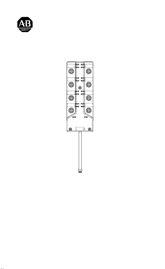
ArmorBlock LP2 16 Sinking Input Module
(Cat. No. 1792D-16BT0LP )
I-0
I-15
I-1
I-14
I-2
I-13
I-3
I-12
I-4
I-11
I-5
I-10
I-6
I-9
I-7
I-8
Network Status
Module Status
41620
This ArmorBlock LP2 I/O module (Cat. No. 1792D-16BT0LP ) is a
stand-alone 24V dc I/O product which communicates via a DeviceNet
network. The sealed housing of this module requires no enclosure.
This model has 16 inputs accessed through Y splitter cables.
Package Contents
Your package contains:
• 1 ArmorBlock LP2 Module
• Installation Instructions
Publication 1792D-5.29 - January 1999
Page 2

2 ArmorBlock LP2 16 Sinking Input Module
European Union Directive Compliance
If this product has the CE mark it is approved for installation within the
European Union and EEA regions. It has been designed and tested to meet
the following directives.
EMC Directive
This product is tested to meet Council Directive 89/336/EEC
Electromagnetic Compatibility (EMC) and the followin g stand ards, in
whole or in part, documented in a technical construction file:
• EN 50081-2 EMC - Generic Emission 16BT0LP Standard, Part 2 Industrial Environment
• EN 50082-2 EMC - Generic Immunity Standard, Part 2 - Industrial
Environment
This product is intended for use in an industrial environment.
Low Voltage Directive
This product is tested to meet Council Directive 73/23/EEC Low Voltage,
by applying the safety requirements of EN 61131-2 Programmable
Controllers, Part 2 - Equipment Requirements and Tests.
For specific information required by EN 61131-2, see the appropriate
sections in this publication, as well as the following Allen-Bradley
publications:
• Industrial Automation Wiring and Grounding Guidelines For Noise
Immunity, publication 1770-4.1
• Automation Syst em s Cata lo g, pu blication B111
Install Your ArmorBlock LP2 I/O Module
T o install the mo du le:
• Set the node address and baud rate.
• Mount the module .
• Attach the unit to the DeviceNet trunk.
• Connect the cord sets.
Set the Node Address
Set the node address using RSNetworx for DeviceNet software,
DeviceNetManager software, or another software configuration tool. The
module is equipped with AutoBaud detect. AutoBaud lets the module read
the settings already in use on your DeviceNet network and automatically
adjusts to follow those settings.
Publication 1792D-5.29 - January 1999
Page 3
ArmorBlock LP2 16 Sinking Input Module 3
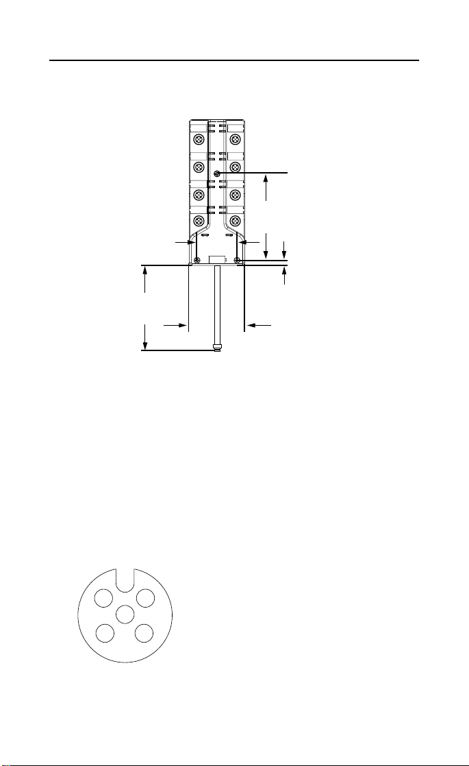
Install the Module
1. Attach the module using the dimensions shown below.
I-0
I-15
I-1
I-14
I-2
I-13
I-3
I-12
I-4
I-11
I-5
I-10
I-9
1.95 in
49.5mm
Network Status
I-6
I-7
I-8
Module Status
4.21 in
107mm
12in
6.25mm
305mm
1.02 in
0.25 in
26.0mm
41620
2. Connect the grey DeviceNet cabl e to the DeviceNet trunk. Use the
1485P-P1R5-MN5R1 T-Part tap to make the connection to round
media. Use the 1485P-P1E4-R5 to connect to the Kwik Link flat media
system.
Connect the Input Cord Sets to the LP2 Module
This module uses 5 pole micro (12mm) style PCB mounted connectors.
Eight micro caps cover the connectors on your module. Remove the caps
and connect your cables to the appropriate ports. This product has two
inputs per connector. Use a “Y” splitter cable for access to al l in put
connections. For more information on these cables, see the Product Data
guide publication 1792-2.1.
Use the micro caps to cover and s eal unused ports. A pinout diagram for
the connectors is shown next.
Input Micro-Connector
1
2
5
3
4
1
Logic Ground is approximately 0.4V abo ve Devi ce Net V - mea sured at t he mod ule .
(View into Sockets)
Pin 1 Sensor Source Voltage
Pin 2 Input B
Pin 3 Return Logic Ground
Pin 4 Input A
Pin 5 Not Used
1
Publication 1792D-5.29 - January 1999
Page 4

4 ArmorBlock LP2 16 Sinking Input Module
ATTENTION:
• Make sure all connectors and caps are securely tightened
!
to properly seal the connections against leaks and
maintain IP67 requirements
• For maximum noise immunity, input and output cable
return wires must be properly terminated. When inputs
and outputs are connected in l oopback, return wires
should be connected together.
• I/O cable length should be less than 30 meters.
Input connectors for this module are shown below.
I-0
I-15
I-1
Connector A
Connector B
Connector C
Connector D
Input 0
Input 1
Input 2
Input 3
Input 4
Input 5
Input 6
Input 7
I-14
I-2
I-13
I-3
I-12
I-4
I-11
I-5
I-10
I-6
I-9
I-7
I-8
Input 15
Input 14
Input 13
Input 12
Input 11
Input 10
Input 9
Input 8
Connector H
Connector G
Connector F
Connector E
Network Status
Module Status
30722-M
DeviceNet Cable
Refer to the DeviceNet Cable and Planning Installation manual for more
information on DeviceNet cabling for you module.
Publication 1792D-5.29 - January 1999
Page 5

ArmorBlock LP2 16 Sinking Input Module 5
Communicate With Your ArmorBlock LP2 Module
This ArmorBlock module’s I/O is exchanged with the master through a
polled, change of state, or cyclic connection.
The module produces input data as follows:
Type of I/O Connections Consumes Produces
Cyclic 0 Byte 2 Bytes
Polled 0 Byte 2 Bytes
Change of State 0 Byte 2 Bytes
Cyclic - allows configuration of the block as an I/O client. The block will
produce its I/O cyclically at the rat e configured.
Polled - a master initiates communication by sending its polled I/O
message to the module. The 16 input module scans the inputs producing a
response that reflects their status.
Change of state - productions occur when an input changes. If no input
change occurs within the expected packet rate, a heartbeat production
occurs. This heartbeat production tells the scanner module that the module
is alive and ready to commu nicate.
Refer to the table below for the word/bit definitions.
Bit 0706050403020100
Produces 0
Produces 1
I7 I6 I5 I4 I3 I2 I1 I0
I15 I14 I13 I12 I11 I10 I9 I8
Where:OW = Off Wire I = Input
Byte Bit Description
00-07 Input status bits: When the bit is set (1), the input is on. Bit
Produces 0
Produces 1
00 = input 0, bit 01= input 1, bit 02 = input 2, bit 03 =
input 3, bit 04 = input 4, bit 05 = input 5, bit 06 = input 6,
bit 07 = input 7
00-07 Input status bits: Bit 00 = input 8, bit 01= input 9, bit 02 =
input 10, bit 03 = input 11, bit 04 = input 12, bit 05 = input
13, bit 06 = input 14, bit 07 = input 15
The DeviceNet Network uses advanced network technology, producer/
consumer communication, to increase network fun c tionality and
throughput. Visit our website at http://www.ab.com/networks
for producer/
consumer technology information and updates.
Publication 1792D-5.29 - January 1999
Page 6

6 ArmorBlock LP2 16 Sinking Input Module
Troubleshoot with the Indicators
This module has the following indicators:
• Network status indicator
• Module status indicator
• Individual point status indicat ors for inputs 0, thro u gh 15
Point indicators for
inputs 0 and 1
Connector A
I-0
I-15
I-1
I-14
Point indicators for
inputs 14 and 15
Connector H
Point indicators for
inputs 2 and 3
Connector B
Point indicators for
inputs 4 and 5
Connector C
Point indicators for
inputs 6 and 7
Connector D
DeviceNet
Indicators
Module Status Indicator
Indication Status
None No Power
Green
Blinking
Solid
Needs Commissioning
Operating Normal
Red
Blinking
Solid
Recoverable Fault
Unrecoverable Fault
I-2
I-13
I-3
I-12
I-4
I-11
I-5
I-10
I-9
I-6
I-8
I-7
Network Status
Module Status
LED Assignments
Point indicators for
inputs 12 and 13
Connector G
Point indicators for
inputs 10 and 11
Connector F
Point indicators for
inputs 8 and 9
Connector E
30722-M
Publication 1792D-5.29 - January 1999
Page 7

7 ArmorBlock LP2 16 Sinking Input Module
Network Status Indicator
Indication Status
None Not On-line
Green
Blinking
Solid
Red
Blink
Solid
I/O Status Indicators
On-line/No Connections
On-line/Connected
Connection Timed Out
Failed Communication: A duplicate
node address exists or the module is at
the wrong baud rate.
Function Module Status Indicator
Inputs Green
Green
Point Indicator
None
Yellow
Condition
No valid input
Valid input
Specifications
16 Input Module - Cat. No. 1792D-16BT0LP
Sinking Input Specifications Max Min
Inputs per block 16 - 3 wire or dry contact PNP devices or 8 - 4 wire
Sensor Source Current (per input) 50mA per point
Off-Wire Sense Current 0.5mA On-state Voltage 25V dc 10V dc
On-state Current 10mA 2mA
Off-state Voltage 5V dc
Off-state Current 1.5mA
General Specifications
Indicators Network Status - red/green
Communication Rate • 125Kbps @ 500 meters(1600 feet) for thick
PNP devices
Module Status - red/green
Point LED - yellow
cable, flat media length 375 meters
• 250Kbps @ 200 meters(600 feet) for thick cable,
flat media length 150 meters
• 500Kbps @ 100 meters (330 feet) for thick
cable, flat media length 75 meters
Publication 1792D-5.29 - January 1999
Page 8

8 ArmorBlock LP2 16 Sinking Input Module
16 Input Module - Cat. No. 1792D-16BT0LP
Sinking Input Specifications Max Min
DeviceNet Power Voltage
Current
25V dc
150mA max (no sensors)
11V dc
1.1A (full load)
Dimensions (assembled to base)
inches - (Millimeters)
Environmental Conditions
Operational Temperature
Storage Temperature
Relative Humidity
Shock Operating
Non-operating
Vibration
1.023H x 2.7w x6.85D
(26)H x (68.5)W x (174)D
o
-25 to 60
-25 to 80
(-13 to 140oF)
o
C (-13 to 176OF)
Up to 100%
30g peak acceleration, 11 (+1) ms pulse width
50g peak acceleration, 11(+1)ms pulse width
Tested 10g @ 10-500Hz per IEC 68-2-6
Conductors Publication DN-6.7.2
Enclosure Meets or exceeds IP67
Agency Certification
(when product is marked)
• CE marked for all applicable directives
This product has been tested at an Open DeviceNet Vendor Association,
Inc. (ODVA) authorized independent test laboratory and found to comply
with ODVA Conformance Test Software Composite Test Version 11.
ArmorBlock, ArmorBlock LP2 and DeviceNetManager are trademarks of Rockwell Automation.
Publication 1792D-5.29 - January 1999 PN 955134-77
1999 Rockwell International. All Rights Reserved. Printed in USA
 Loading...