

Page 1
Installation Instructions
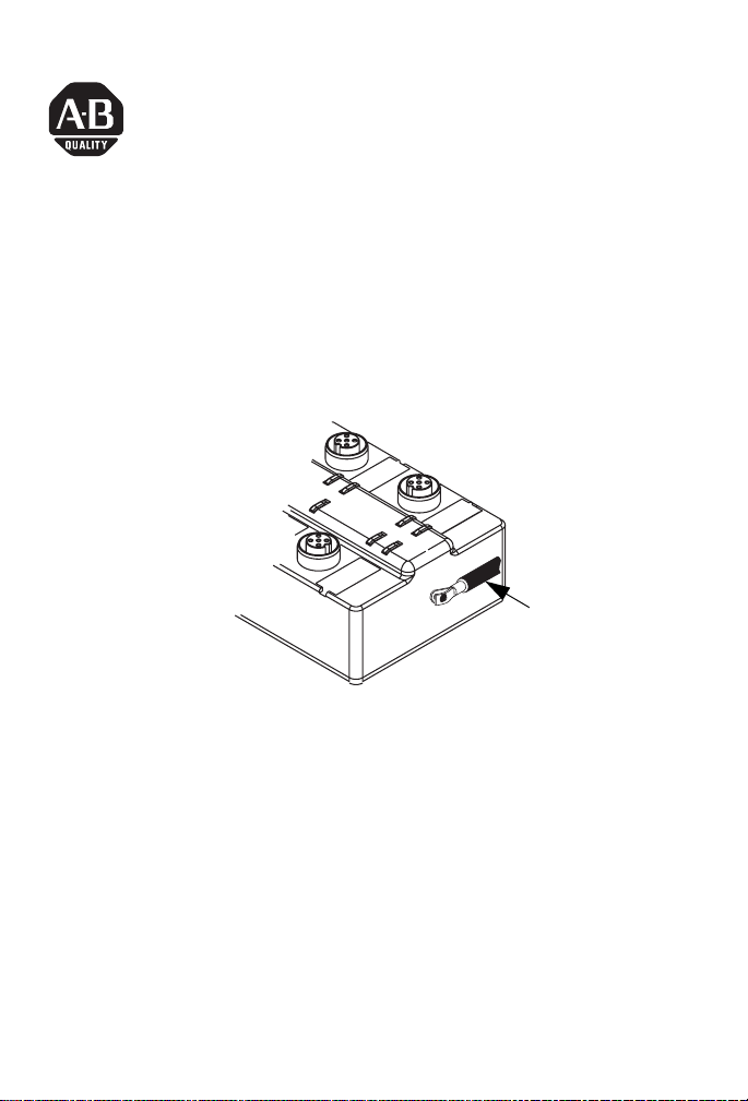
ArmorBlock MaXum 12 Input/
4 Output Module With Ground Lug
Cat. No. 1792D-12BT4PE
Ground lug
43881
This ArmorBlock MaXum I/O module (Cat. No. 1792D-12BT4PE) is
a stand-alone 24V dc I/O product, which communicates via a
DeviceNet network. The sealed housing of this module requires no
enclosure.
This module has 12 inputs and 4 outputs accessed through Y splitter
cables. Inputs are 24V dc devices. Four self-protected 24V dc outputs
can provide up to 2.0 amp each. Diagnostic features are short circuit,
open wire and no load detection reported to the connector level for
inputs and to point level for outputs. Local logic control has been
included.
An external lug exists to ground the block.
Publication 1792D-IN056A-EN-P - October 2004
Page 2
2 ArmorBlock MaXum 12 Input/ 4 Output Module With Ground Lug
S
Important User Information
Solid state equipment has operational characteristics differing from those of
electromechanical equipment. Safety Guidelines for the Application, Installation and
Maintenance of Solid State Controls (Publication SGI-1.1 available from your local Rockwell
Automation sales office or online at http://www.ab.com/manuals/gi) describes some
important differences between solid state equipment and hard-wired electromechanical
devices. Because of this difference, and also because of the wide variety of uses for solid
state equipment, all persons responsible for applying this equipment must satisfy
themselves that each intended application of this equipment is acceptable.
In no event will Rockwell Automation, Inc. be responsible or liable for indirect or
consequential damages resulting from the use or application of this equipment.
The examples and diagrams in this manual are included solely for illustrative purposes.
Because of the many variables and requirements associated with any particular installation,
Rockwell Automation, Inc. cannot assume responsibility or liability for actual use based on
the examples and diagrams.
No patent liability is assumed by Rockwell Automation, Inc. with respect to use of
information, circuits, equipment, or software described in this manual.
Reproduction of the contents of this manual, in whole or in part, without written permission
of Rockwell Automation, Inc. is prohibited.
Throughout this manual, when necessary we use notes to make you aware of safety
considerations.
WARNING
Identifies information about practices or circumstances that can cause an explosion in a
hazardous environment, which may lead to pers onal injury or death, property damage, or
economic loss.
IMPORTANT
ATTENTION
HOCK HAZARD
BURN HAZARD
Publication
Identifies information that is critical for successful application and understanding of the
product.
Identifies information about practices or ci rcumstances that can lead to pe rsonal injury or
death, property damage, or economic loss. Attentions help you:
• identify a hazard
• avoid a hazard
• recognize the consequence
Labels may be located on or inside the equipment (e.g., drive or motor) to alert people
that dangerous voltage may be present.
Labels may be located on or inside the equipment (e.g., drive or motor) to alert people
that surfaces may be dangerous temperatures.
1792D-IN056A-EN-P - October 2004
Page 3

ArmorBlock MaXum 12 Input/ 4 Output Module With Ground Lug 3
ATTENTION
Environment and Enclosure
This equipment is intended for use in a Pollution Degree 2 industrial
environment, in overvoltage Category II applications (as defined in IEC
publication 60664-1), at altitudes up to 2000 meters without derating.
This equipment is considered Group 1, Class A industrial equipment according
to IEC/CISPR Publication 11. Without appropriate precautions, there may be
potential difficulties ensuring electromagnetic compatibility in other
environments due to conducted as well as radiated disturbance.
This equipment is supplied as "open type" equipment. It must be mounted
within an enclosure that is suitably designed for those specific environmental
conditions that will be present and appropriately designed to prevent
personal injury resulting from accessibility to live parts. The interior of the
enclosure must be accessible only by the use of a tool. Subsequent sections
of this publication may contain additional information regarding specific
enclosure type ratings that are required to comply with certain product safety
certifications.
NOTE: See NEMA Standards publication 250 and IEC publication 60529, as
applicable, for explanations of the degrees of protection provided by different
types of enclosure. Also, see the appropriate sections in this publication, as
well as the Allen-Bradley publication 1770-4.1 ("Industrial Automation Wiring
and Grounding Guidelines"), for additional installation requirements
pertaining to this equipment.
Package Contents
Your package contains:
• 1 ArmorBlock MaXum module
• these installation instructions
(Note: Cable bases are ordered and shipped separately.)
Publication
1792D-IN056A-EN-P - October 2004
Page 4
4 ArmorBlock MaXum 12 Input/ 4 Output Module With Ground Lug
Install Your ArmorBlock MaXum I/O Module
To install the module you must:
• Set the node address
• Mount the module to the cable base
• Connect the input/output cord sets to the MaXum module
• Communicate with your ArmorBlock MaXum I/O module
Each of these steps is explained in the following procedures.
ATTENTION
Preventing Electrostatic Discharge
This equipment is sensitive to electrostatic discharge, which can cause
internal damage and affect normal operation. Follow these guidelines when
you handle this equipment:
• Touch a grounded object to discharge potential static.
• Wear an approved grounding wriststrap.
• Do not touch connectors or pins on component boards.
• Do not touch circuit components inside the equipment.
• If available, use a static-safe workstation.
• When not in use, store the equipment in appropriate static-safe
packaging.
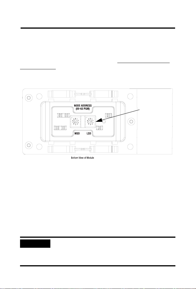
Set the Node Address
Valid node addresses are 00 through 63.
Set the node address using the rotary switches, RSNetWorx for
DeviceNet, or another software configuration tools. Setting the
switches to a number from 64 through 99 lets the software have
address control.
Each module is shipped set for node address 63. The switches are
located on the underside of the module. The two switches are:
• MSD (most significant digit)
• LSD (least significant digit)
Publication
1792D-IN056A-EN-P - October 2004
Page 5
ArmorBlock MaXum 12 Input/ 4 Output Module With Ground Lug 5
To reset the node address, use a small blade screwdriver to rotate the
switches. Line up the small black dot on the switch with the number
setting you wish to use.
The rotary switches are read at module power up only. Settings from
64 through 99 cause the module to use the last valid node address
stored internally. For example, the last setting was 40. If a change is
made to 68, and then you power up, the address will default to 40.
Refer to the following illustration of the node address.
Node Address is
set at 62; see
small black dots.
41462
The module is equipped with AutoBaud detect. AutoBaud lets the
module read the settings already in use on your DeviceNet network
and automatically adjusts to follow those settings.
Mount the Module to the Cable Ba se
This module mounts to the following cable bases:
• 1792D-CBFM for KwikLink flat media installation
• 1792D-CB12 for 12mm drop cable installation
• 1792D-CB18P for round media DeviceNet and output power
• other optional cable base assembly
IMPORTANT
The cable base should already be installed. For
more information about the cable base, see
publication 1792D-IN036 (CB18P) or 1792D-IN009
(CBFM, CB12).
Publication
1792D-IN056A-EN-P - October 2004
Page 6
6 ArmorBlock MaXum 12 Input/ 4 Output Module With Ground Lug
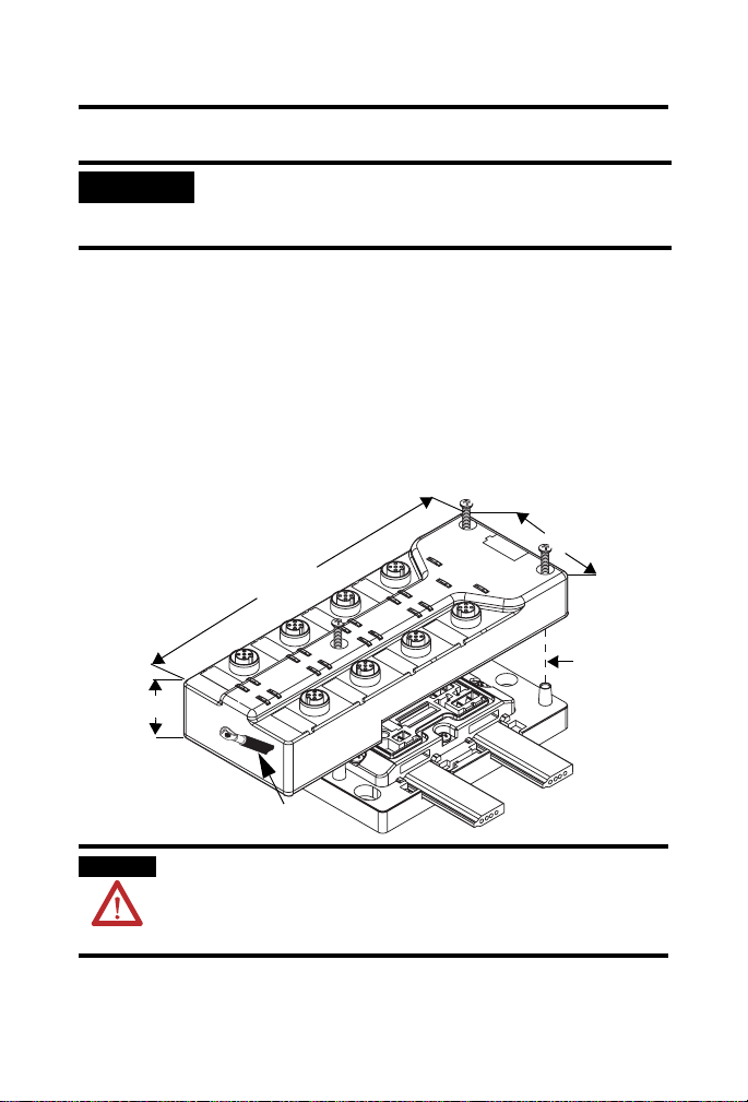
To install the module:
IMPORTANT
Proper alignment of the screws is necessary to
complete the connections between the module
contacts and the cable contacts.
1. Position the module over the mounted cable base. Align the
three captive screws in the module with the accepting
receptacles in the base.
2. Tighten the screws with a torque of 8 inch-pounds to secure
the module to the base.
Note: Dimensions change according to the cable base and
module combination used.
2
.
7
i
n
.
.9in. (48.26mm)
Cable Base
1792D-CBFM is used
for this example.
6.85in. (174)mm
Ground lug
Align the
screws to
properly
secure the
module to
the base.
(
6
8
.
6
m
m
)
43880
WARNING
Publication
When used in a Class I, Division 2, hazardous
location, this equipment must be mounted in a
suitable enclosure with proper wiring method that
complies with the governing electrical codes.
1792D-IN056A-EN-P - October 2004
Page 7

ArmorBlock MaXum 12 Input/ 4 Output Module With Ground Lug 7
Connect the Input / Output Cord Sets to the MaXum Module
This module uses 5 pin micro (12mm) style PCB mounted connectors.
Eight micro caps cover the connectors on your module. Remove the
caps and connect your cord sets to the appropriate ports. This
product has two inputs or outputs per I/O connector. Use a “Y”
splitter cable for access to all I/O connections.
Use the micro caps to cover and seal unused ports. Pinout diagrams
for the connectors are shown below.
Input Micro-Connector
(view into socket)
Pin 1 Sensor Source voltage
Pin 2 Input B
Pin 3 Return Logic Ground
Pin 4 Input A
Pin 5 PE
Output Micro-Connector
(view into socket)
Pin 1 Not Used
Pin 2 Output B
Pin 3 Auxiliary Power Ground
Pin 4 Output A
1
Logic Ground is approximately 0.4V above DeviceNet V- measured at the module.
Pin 5 PE
Molded I/O cables with LEDs embedded in the connector are
incompatible with MaXum universal sink/source inputs.
1
41452
WARNING
If you connect or disconnect the communications cable
with power applied to this module or any device on the
network, an electrical arc can occur. This could cause an
explosion in hazardous location installations.
Publication
1792D-IN056A-EN-P - October 2004
Page 8

8 ArmorBlock MaXum 12 Input/ 4 Output Module With Ground Lug
Refer to publication 889-5.0 for Rockwell Automation cables and cord
sets offerings.
WARNING
IMPORTANT
ATTENTION
Use supply wires suitable for 30°C above
surrounding ambient.
If the devices (sensors) connected to the input
connections require Class 2 power to operate, the
DeviceNet connections of this equipment must be
powered by a Class 2 source.
• Make sure all connectors and caps are securely
tightened to properly seal the connections
against leaks and maintain IP67 requirements.
• For maximum noise immunity, input and output
cable return wires must be properly terminated.
When inputs and outputs are connected in
loopback, return wires should be connected
together.
• I/O cable length should be less than 30 meters.
Publication
1792D-IN056A-EN-P - October 2004
Page 9

ArmorBlock MaXum 12 Input/ 4 Output Module With Ground Lug 9
I/O connectors for this module are shown below.
O-0
O-3
O-1
Logic Status
O-2
I-0
I-11
I-1
I-10
I-2
I-9
I-3
I-8
I-4
I-7
I-5
I-6
Auxiliary Power
Net/Mod Status
42339
Connector A
Connector B
Connector C
Output 0
Output 1
Input 0
Input 1
Input 2
Input 3
Input 4
Input 5
Output 3
Output 2
Input 11
Input 10
Input 9
Input 8
Input 7
Input 6
Connector F
Connector E
Connector D
WARNING
If you connect or disconnect wiring while the
field-side power is on, an electrical arc can occur.
This could cause an explosion in hazardous
location installations. Be sure that power is
removed or the area is nonhazardous before
proceeding.
Output Power and DeviceNet Cables
Output power and DeviceNet cables are described in the installation
publications for the cable base assembly of your choice. Refer to the
following publications:
• 1792D-IN009 ArmorBlock MaXum Cable Base Installation
Instructions
• DN-6.7.2 DeviceNet Cable Planning and Installation Manual
Publication
1792D-IN056A-EN-P - October 2004
Page 10

10 ArmorBlock MaXum 12 Input/ 4 Output Module With Ground Lug
Communicate With Your ArmorBlock MaXum I/O Module
This ArmorBlock module’s I/O is exchanged with the master through
a cyclic, poll, or change-of-state connection.
The module consumes and produces I/O data as follows:
Type of I/O Connections Consumes Produces
Cyclic 1 Byte 4 Bytes
Polled 1 Byte 4 Bytes
Change-of-State 1 Byte 4 Bytes
Cyclic - allows configuration of the block as an I/O client. The block
will produce and consume its I/O cyclically at the rate configured.
Polled - a master initiates communication by sending its polled I/O
message to the module. The 12 input / 4 output module consumes
the message, updates outputs, and produces a response. The
response has input data, input faults, output faults, and the status of
the auxiliary power.
Change-of-State - productions occur when an input changes or a
fault condition occurs. If no input or fault condition change occurs
within the expected packet rate, a heartbeat production occurs. This
heartbeat production tells the scanner module that the
I/O module is alive and ready to communicate. Consumption occurs
when data changes and the master produces new output data to the
I/O block.
Refer to the table below for the word/bit definitions.
Bit 07 06 05 04 03 02 01 00
Produces 0 I7 I6 I5 I4 I3 I2 I1 I0
Produces 1 ISC-D ISC-C ISC-B ISC-A I11 I10 I9 I8
Produces 2 OW-F OW-E OW-D OW-C OW-B OW-A ISC-F ISC-E
Produces 3 RSVD OPWR RSVD RSVD OFLT3 OFLT2 OFLT1 OFLT0
Consumes 0 RSVD RSVD RSVD RSVD O3 O2 O1 O0
Where: I = Input, ISC = Input Short Circuit in Sensor Source Voltage, OW = Off Wire,
RSVD = Reserved, OPWR = Output Power (auxiliary power), OFLT = Output fault, O = O utp ut
Publication
1792D-IN056A-EN-P - October 2004
Page 11

ArmorBlock MaXum 12 Input/ 4 Output Module With Ground Lug 11
The DevicLogix Product assembly for the 1792D-8BT8DPE is as
follows:
Bit 07 06 05 04 03 02 01 00
Produces 0 I7 I6 I5 I4 I3 I2 I1 I0
Produces 1 ISC-D ISC-C ISC-B ISC-A I11 I10 I9 I8
Produces 2 OW-F OW-E OW-D OW-C OW-B OW-A ISC-F ISC-E
Produces 3 OPWR Logic Ena
Produces 4 O3 O2 O1 O0
Produces 5 PNB7 PNB6 PNB5 PNB4 PNB3 PNB2 PNB1 PNB0
Where: I = Input, ISC=Input Short Circuit in Sensor Source Voltage, OW = Off Wire,
OPWR= Output Power (auxiliary power), Logic Ena = DeviceLogix enabled, O = Output,
PNB = Produced Network Bit (Network Output)
Publication
1792D-IN056A-EN-P - October 2004
Page 12

12 ArmorBlock MaXum 12 Input/ 4 Output Module With Ground Lug
Byte Bit Description
Produces 0 00-07 Input Status bits: When the bit is set (1), the input is on.
Produces 1 00-03
04-07
Produces 2 00-01
02-07
Produces 3 00-03
06
04, 05, 07
Consumes 0 00-03
04-07
Bit 00 = input 0, bit 01 = input 1, bit 02 = input 2, and so on to
bit 07 = input 7.
Input Status bits: When the bit is set (1), the input is on.
Bit 08 = input 8, bit 09 = input 9, bit 010 = input 10,
bit 011 = input 11.
Input short circuit fault (ISC): ISC-A indicates a short circuit
fault for connector A.
Input short circuit fault (ISC): ISC-B indicates a short circuit
fault for connector B.
Input short circuit fault (ISC): ISC-C indicates a short circuit
fault for connector C.
Input short circuit fault (ISC): ISC-D indicates a short circuit
fault for connector D.
Input short circuit fault (ISC): ISC-E indicates a short circuit
fault for connector E.
Input short circuit fault (ISC): ISC-F indicates a short circuit
fault for connector F.
Input off wire fault (OW): OW-A indicates an off-wire fault for
connector A.
Input off wire fault (OW): OW-B indicates an off-wire fault for
connector B.
Input off wire fault (OW): OW-C indicates an off-wire fault for
connector C.
Input off wire fault (OW): OW-D indicates an off-wire fault for
connector D.
Input off wire fault (OW): OW-E indicates an off-wire fault for
connector E.
Input off wire fault (OW): OW-F indicates an off-wire fault for
connector F.
Output no load or overload fault (OFLT): - When the bit is set
(1) an output fault has occurred. OFLT0 corresponds to output
0, OFLT1 corresponds to output 1, OFLT2 corresponds to output
2, OFLT3 corresponds to output 3
Output Power Fault (OPWR): When the bit is set (1) auxiliary
power is not present.
RSVD = Reserved
Output bits: When the bit is set (1), the output will be turned
on. Bit 00 corresponds to output O0, bit 01 corresponds to
output O1, bit 02 to output O2, bit O3 to output 03.
RSVD = Reserved
Publication
1792D-IN056A-EN-P - October 2004
Page 13

ArmorBlock MaXum 12 Input/ 4 Output Module With Ground Lug 13
1
The DeviceNet Network uses advanced network technology,
producer/consumer communication, to increase network
functionality and throughput. Visit our web site at
http://www.ab.com/networks for producer/consumer technology
information and updates.
Troubleshoot With the Indicators
This module has the following indicators:
• Network/Module status indicator
• Logic status indicator
• Auxiliary power indicator
• Individual I/O status indicators for outputs 0 through 3 and inputs
0 through 11
Refer to the following table for point indicators.
Point indicators
for outputs 0 and 1
Point indicators
for inputs 0 and 1
Connector A
Point indicators
for inputs 2 and 3
Connector B
Point indicators
for inputs 4 and 5
Connector C
Module
Status
Indicators
O-0
O-3
O-1
O-2
I-0
I-11
I-1
I-10
I-2
I-9
I-3
I-8
I-7
I-4
I-5
I-6
Auxiliary Power
Logic Status
Net/Mod Status
LED Assignments
Publication
Point indicators
for outputs 2 and 3
Point indicators
for inputs 10 and 1
Connector F
Point indicators
for inputs 8 and 9
Connector E
Point indicators
for inputs 6 and 7
Connector D
42339
1792D-IN056A-EN-P - October 2004
Page 14

14 ArmorBlock MaXum 12 Input/ 4 Output Module With Ground Lug
The following table describes the network and module status
indicator.
Net/Mod Status Indicator
Indicator Status
Off No power or auto bauding
Flashing Green/Off On line but not connected
Solid Green On line, link OK, connected
Flashing Red Recoverable fault - module configuration error
I/O connection fault - one or more I/O connections in the timed-out state
Solid Red Unrecoverable fault
Communication failure - duplicate node address present or incorrect baud
rate
Green to Red to Off At powerup only - LED test
The following table describes the logic status indicator.
Logic Status Indicator
Indicator Status
Off Logic is disabled
Solid Green Logic is enabled
Flashing Green Local forces are applied and local logic is enabled
The following table describes the auxiliary status indicator.
Auxiliary Status Indicator
Indicator Status
None No auxiliary power
Solid Green Auxiliary power present
Publication
1792D-IN056A-EN-P - October 2004
Page 15

ArmorBlock MaXum 12 Input/ 4 Output Module With Ground Lug 15
The following table describes individual I/O status indicators.
I/O Status Indicators
Function Module Status
Indicator
Outputs Green
Green
Module Status blink red
Module Status blink red
Module Status blink red
Module Status blink red
Inputs Green
1
Only the first LED of each input connector will light as red when twin inputs are used.
Green
Module Status blink red
Module Status blink red
Point
Indicator
None
Yellow
Orange
Red
Orange
Red
None
Yellow
Red
Blink red
Status
1
Output not energized
Output energized
Output shorted - auto restart
Output shorted - latching
Output no load - auto restart
Output no load - latching
No valid input
Valid input
Short on input connection
Off wire on input connection
Specifications
12 Input / 4 Output Module - Cat. No. 1792D-12BT4PE
Input Specifications Maximum Minimum
Inputs per block 12 - 3 wire or dry contact PNP devices or 6 - 4 wire PNP devices
Sensor Source Current (per input) See the graph located after this Specifications table.
Off-wire Sense Current 0.5mA On-state Voltage 25V dc 10V dc
On-state Current 10mA 2mA
Off-state Voltage 5V dc Off-state Current - 1.5mA
Output Specifications Maximum Minimum
Outputs per block 4 sourcing outputs labeled O0 through O3
Off Peak Blocking Voltage 30V 10V
On-state Voltage Drop 1V On-state Current 2.0A Off-state Leakage 1.5mA Module Current (all outputs) 4.0A -
1
1
Publication
1792D-IN056A-EN-P - October 2004
Page 16

16 ArmorBlock MaXum 12 Input/ 4 Output Module With Ground Lug
12 Input / 4 Output Module - Cat. No. 1792D-12BT4PE
Output Specifications (cont.) Maximum Minimum
Surge Current - for 10ms, repeatable
every 2s
No Load Sense Current (On-state) 0.18A -
General Specifications Maximum Minimum
DeviceNet Power Voltage
Refer to the graphs in the DeviceNet
Power Supply Requirements section of
the ArmorBlock MaXum I/O and
ArmorBlock I/O Selection Guide, pub.
no. 1792-SG001.
Auxiliary Power Voltage
Current
Indicators Net/Mod Status - red/green
Communication Rate • 125Kbps @ 500 meters(1600 feet) for thick cable, flat
Dimensions (assembled to base)
inches - (Millimeters)
Operational Temperature
Storage Temperature
Relative Humidity IEC 60068-2-30 (Test Db, Un-packaged Non-operating Damp
Vibration IEC 60068-2-6 (Test Fc, Operating):
Operating Shock IEC 60068-2-27 (Test Ea, Unpackaged Shock):
Non-Operating Shock IEC 60068-2-27 (Test Ea, Unpackaged Shock):
Current
4.0A -
25V dc max
175mA max (no sensors)
30V dc max
4A max
Logic Status - green
Auxiliary Power - green
Point LED - yellow/orange/red
media length 375 meters (1230 feet)
• 250Kbps @ 200 meters(600 feet) for thick cable, flat
media length 150 meters (492 feet)
• 500Kbps @ 100 meters (330 feet) for thick cable, flat
media length 75 meters (246 feet)
1.9H x 2.7W x 6.9D
(48)H x (69)W x (174)D
IEC 60068-2-1 (Test Ad, Operating Cold),
IEC 60068-2-2 (Test Bd, Operating Dry Heat),
IEC 60068-2-14 (Test Nb, Operating Thermal Shock):
-25 to 60° (-13 to 140°F)
IEC 60068-2-1 (Test Ab, Un-packaged Non-operating Cold),
IEC 60068-2-2 (Test Bb, Un-packaged Non-operating Dry
Heat),
IEC 60068-2-14 (Test Na, Un-packaged Non-operating
Thermal Shock):
-25 to 80°C (-13 to 176°F)
Heat):
5 to 100% non-condensing
10g @ 10-500 Hz
30g
50g
11V dc min
up to 1.6A (12 sensors @
50mA per sensor)
10V dc min
4A max
Publication
1792D-IN056A-EN-P - October 2004
Page 17

ArmorBlock MaXum 12 Input/ 4 Output Module With Ground Lug 17
12 Input / 4 Output Module - Cat. No. 1792D-12BT4PE
General Specifications (continued)
Emissions CISPR 11:
ESD Immunity IEC 61000-4-2:
Radiated RF Immunity IEC 61000-4-3:
EFT/B Immunity IEC 61000-4-4:
Surge Transient Immunity IEC 61000-4-5:
Conducted RF Immunity IEC 61000-4-6:
Conductors Publication DN-6.7.2
Enclosure Meets IP67
Supply Voltages/Voltage Ranges DNet Power: 11V dc to 25V dc;
Supply Power/Current Ratings DNet current:1.6A;
Isolation voltage (continuous-voltage
withstand rating)
Wire Size Use 14-22 AWG wire with insulation temperature rating of
Wiring Category
1
Group 1, Class A
6kV contact discharges
8kV air discharges
10V/m with 1kHz sine-wave 80%AM from 30MHz to
2000MHz
10V/m with 200Hz 50% Pulse 100%AM at 900MHz
10V/m with 200Hz 50% Pulse 100%AM at 1890MHz
±2kV at 5kHz on power ports
±2kV at 5kHz on signal ports
±2kV at 5kHz on communications ports
±1kV line-line(DM) and ±2 line-earth(CM) on power ports
±1kV line-line(DM) and ±2kV line-earth(CM) on signal ports
±2kV line-earth(CM) on communications ports
10Vrms with 1kHz sine-wave 80%AM from 150kHz to 80MHz
Auxiliary Power: 10V dc to 30V dc
Input current: 50mA;
Output power: 60VA DC-13/SQ;
Outputs 4A total;
Auxiliary current:4A
Tested to withstand 750V dc for 60 seconds
75°C min.See Publication DN-6.7.2; Category: 2.
2 - on signal ports
2 - on power ports
2 - on communications ports
Publication
1792D-IN056A-EN-P - October 2004
Page 18

18 ArmorBlock MaXum 12 Input/ 4 Output Module With Ground Lug
12 Input / 4 Output Module - Cat. No. 1792D-12BT4PE
General Specifications (continued)
Certifications:
(when product is marked)
1. Use this Conductor Category information for planning conductor routing. Refer to Publication
2. See the Product Certification link at www.ab.com for Declarations of Conformity, Certificates, and
2
1770-4.1, "Industrial Automation Wiring and Grounding Guidelines".
other certification details.
1.0
Sensor Source
Current - Amp
Note: This is an
illustration of
total current for
all 12 inputs.
0.8
0.6
0.4
0.2
0.0
Divide by
12 for current per
input.
ArmorBlock, ArmorBlock MaXum, RSNetWorx for DeviceNet, and KwikLink are trademarks of Rockwell
Automation.
DeviceNet is a trademark of Open DeviceNet Vendor Association (ODVA).
CSA CSA Certified Process Control Equipment
CSA CSA Certified Process Control Equipment for
Class I, Division 2 Group A,B,C,D Hazardous
Locations
CE European Union 89/336/EEC EMC Directive,
compliant with:
EN 50082-2; Industrial Immunity
EN 61326; Meas./Control/Lab., Industrial
Requirements
EN 61000-6-2; Industrial Immunity
EN 61000-6-4; Industrial Emissions
EN 61131-2; Programmable Controllers
(Clause 8, Zone A & B)
C-Tick Australian Radiocommunications Act,
compliant with:
AS/NZS CISPR 11; Industrial Emissions
ODVA ODVA conformance tested to DeviceNet
specifications
Temperature=60°C
15 17 2511 13
DeviceNet Voltage -Vdc
21
19 23
42574
Publication
1792D-IN056A-EN-P - October 2004
Page 19

ArmorBlock MaXum 12 Input/ 4 Output Module With Ground Lug 19
T
North American Hazardous Location Approval
The following information applies when operating
this equipment in hazardous locations:
Products marked "CL I, DIV 2, GP A, B, C, D" are suitable
for use in Class I Division 2 Groups A, B, C, D, Hazardous
Locations and nonhazardous locations only. Each product
is supplied with markings on the rating nameplate
indicating the hazardous location temperature code.
When combining products within a system, the most
adverse temperature code (lowest "T" number) may be
used to help determine the overall temperature code of
the system. Combinations of equipment in your system
are subject to investigation by the local Authority Having
Jurisdiction at the time of installation.
WARNING
• Do not disconnect equipment
unless power has been
removed or the area is known
to be nonhazardous.
• Do not disconnect
connections to this
equipment unless power has
been removed or the area is
known to be nonhazardous.
Secure any external
connections that mate to this
equipment by using screws,
sliding latches, threaded
connectors, or other means
provided with this product.
• Substitution of components
may impair suitability for
Class I, Division 2.
• If this product contains
batteries, they must only be
changed in an area known to
be nonhazardous.
Informations sur l'utilisation de cet équipement en
environnements dangereux:
Les produits marqués "CL I, DIV 2, GP A, B, C, D" ne
conviennent qu'à une utilisation en environnements de
Classe I Division 2 Groupes A, B, C, D dangereux et non
dangereux. Chaque produit est livré avec des marquages sur
sa plaque d'identification qui indiquent le code de
température pour les environnements dangereux. Lorsque
plusieurs produits sont combinés dans un système, le code
de température le plus défavorable (code de température le
plus faible) peut être utilisé pour déterminer le code de
température global du système. Les combinaisons
d'équipements dans le système sont sujettes à inspection
par les autorités locales qualifiées au moment de
l'installation.
AVERTISSEMEN
• Couper le courant ou
s'assurer que
l'environnement est classé
non dangereux avant de
débrancher l'équipement.
• Couper le courant ou
s'assurer que
l'environnement est classé
non dangereux avant de
débrancher les
connecteurs. Fixer tous les
connecteurs externes
reliés à cet équipement à
l'aide de vis, loquets
coulissants, connecteurs
filetés ou autres moyens
fournis avec ce produit.
• La substitution de
composants peut rendre
cet équipement inadapté à
une utilisation en
environnement de Classe I,
Division 2.
• S'assurer que
l'environnement est classé
non dangereux avant de
changer les piles.
This product has been tested at an Open DeviceNet Vendor
Association, Inc. (ODVA) authorized independent test laboratory and
found to comply with ODVA Conformance Test. Please contact the
ODVA web site (http://www.odva.org) for listing of products tested
by ODVA independent test labs for further details.
Publication
1792D-IN056A-EN-P - October 2004
Page 20

Rockwell Automation Support
Rockwell Automation provides technical info rmation on the web to assist you
in using its products. At http://support .rockwell aut omation .com, y ou can find
technical manuals, a knowledge base of FAQs, technical and application
notes, sample code and links to software service packs, and a MySupport
feature that you can customize to make the best use of these tools.
For an additional level of technical phone support for installation,
configuration and troubleshooting, we offer TechConnect Support programs.
For more information, contact your local distributor or Rockwell Automation
representative, or visit http://support.rockwellautomation.com.
Installation Assistance
If you experience a problem with a hardware module wit hin the first 24 hours
of installation, please review the information that's contained in this manual.
You can also contact a special Customer Support number for initial help in
getting your module up and running:
United States 1.440.646.3223 Monday – Friday, 8am – 5pm EST
Outside United States Please contact your local Rockwell Automation representative for any
New Product Satisfaction Return
Rockwell tests all of its products to ensure that they are ful ly operational when
shipped from the manufacturing facility. However, if your product is not
functioning and needs to be returned:
United States Contact your distributor. You must provide a Customer Support case number
Outside United States Please contact your local Rockwell Automation representative for return
technical support issues.
(see phone number above to obtain one) to your distributor in order to
complete the return process.
procedure.
Publication 1792D-IN056A-EN-P - October 2004 PN 957928-11
Copyright © 2004 Rockwell Automation, Inc. All rights reserved. Printed in the U.S.A.
 Loading...