

Page 1

Installation Instructions
Compact
Block
Distributed I/O on
Remote I/O
(Cat. No. 1791R-16B0, -0B16P, -8B8P, -4B4P, -8V8P)
1791R CompactBlock™ I/O modules are stand-alone 24V dc Block
I/O products that communicate via a Remote I/O link. Each Remote
I/O node consists of either one base module or one base module and
one expansion module. Any expansion module can be coupled with
any base module. CompactBlock 1791R consists of only base
modules. The expansion modules are part of the CompactBlock
1791D family of products.
CompactBlock Remote I/O modules must be installed in a secondary
enclosure. Base modules are equipped with 8 to 16 points.
CompactBlock Remote I/O provides both sinking and sourcing
inputs and outputs. Sinking inputs are 24V dc NEMA Type 3
compatible. Self-protected 24V dc outputs can provide up to 0.5 amp
each.
Important User Information
Because of the variety of uses for the products described in this
publication, those responsible for the application and use of these
products must satisfy themselves that all necessary steps have been
taken to assure that each application and use meets all performance
and safety requirements, including any applicable laws, regulations,
codes and standards. In no event will Allen-Bradley be responsible or
liable for indirect or consequential damage resulting from the use or
application of these products.
Publication 1791R-IN001A-EN-P - February 2002
Page 2

2 CompactBlock Distributed I/O on Remote I/O
WARNING
!
ATTENTION
!
Any illustrations, charts, sample programs, and layout examples
shown in this publication are intended solely for purposes of
example. Since there are many variables and requirements associated
with any particular installation, Allen-Bradley does not assume
responsibility or liability (to include intellectual property liability) for
actual use based upon the examples shown in this publication.
Allen-Bradley publication SGI-1.1, Safety Guidelines for the
Application, Installation and Maintenance of Solid-State Control
(available from your local Allen-Bradley office), describes some
important differences between solid-state equipment and
electromechanical devices that should be taken into consideration
when applying products such as those described in this publication.
Reproduction of the contents of this copyrighted publication, in
whole or part, without written permission of Rockwell Automation, is
prohibited.
Throughout this publication, notes may be used to make you aware
of safety considerations. The following annotations and their
accompanying statements help you to identify a potential hazard,
avoid a potential hazard, and recognize the consequences of a
potential hazard:
Identifies information about practices or
circumstances that can cause an explosion in a
hazardous environment, which may lead to
personal injury or death, property damage, or
economic loss.
Publication 1791R-IN001A-EN-P - February 2002
Identifies information about practices or
circumstances that can lead to personal injury or
death, property damage, or economic loss.
Page 3

CompactBlock Distributed I/O on Remote I/O 3
IMPORTANT
ATTENTION
!
Identifies information that is critical for
successful application and understanding of the
product.
Environment and Enclosure
This equipment is intended for use in a Pollution
Degree 2 industrial environment, in overvoltage
Category II applications (as defined in IEC
publication 60664-1), at altitudes up to 2000
meters without derating.
This equipment is considered Group 1, Class A
industrial equipment according to IEC/CISPR
Publication 11. Without appropriate precautions,
there may be potential difficulties ensuring
electromagnetic compatibility in other
environments due to conducted as well as
radiated disturbance.
This equipment is supplied as "enclosed"
equipment. It should not require additional
system enclosure when used in locations
consistent with the enclosure type ratings stated
in the Specifications section of this publication.
Subsequent sections of this publication may
contain additional information regarding specific
enclosure type ratings, beyond what this product
provides, that are required to comply with
certain product safety certifications.
NOTE: See NEMA Standards publication 250
and IEC publication 60529, as applicable, for
explanations of the degrees of protection
provided by different types of enclosure. Also,
see the appropriate sections in this publication,
as well as the Allen-Bradley publication 1770-4.1
("Industrial Automation Wiring and Grounding
Guidelines"), for additional installation
requirements pertaining to this equipment.
Publication 1791R-IN001A-EN-P - February 2002
Page 4

4 CompactBlock Distributed I/O on Remote I/O
ATTENTION
!
Installing CompactBlock I/O
Follow these steps, to install the 1791R I/O module:
1. Set the Node Address on the Base Module.
2. Mount the Block(s).
3. Connect the Input/Output Wires to the Block.
4. Connect the RIO Cable.
5. Select termination for the module.
6. Connect power to the module.
7. Remove the terminal block.
8. Insert the terminal block.
9. Communicate with the 1791R Module.
These steps are explained in detail in the following
procedures.
Preventing Electrostatic Discharge
This equipment is sensitive to electrostatic
discharge, which can cause internal damage and
affect normal operation. Follow these guidelines
when you handle this equipment:
Publication 1791R-IN001A-EN-P - February 2002
• Touch a grounded object to discharge
potential static.
• Wear an approved grounding wriststrap.
• Do not touch connectors or pins on
component boards.
• Do not touch circuit components inside the
equipment.
• If available, use a static-safe workstation.
• When not in use, store the equipment in
appropriate static-safe packaging.
Page 5
CompactBlock Distributed I/O on Remote I/O 5
IMPORTANT
Vi
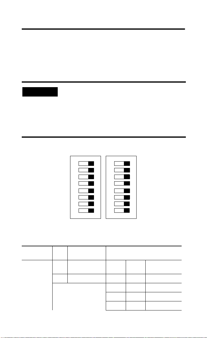
Set the Node Address on the Base Module
The node address for network connection is set using two 8-bit DIP
switches. To set the node address, lift the door containing the status
LEDs on the top left side of the module. The switches are read at
module power up only. The rack address setting and the starting
quarter setting are described below.
It is important to monitor the rack fault bit.
When installing a system for the first time, it is
possible to mistakenly put devices with duplicate
rack addresses on the same network. Blocks
with duplicate addresses may in certain instances
cause outputs to toggle on/off until the duplicate
address error is corrected.
ew when looking into module.
DIP Switch Settings
The 1791R DIP switches are described in the table below.
DIP Switch No. Description Starting Quarter
SW1
8
7
6
5
4
3
ON
2
1
1 Starting Quarter
2 Starting Quarter
8
7
6
5
4
3
ON
SW1-2 SW1-2
2
1
Module
Group
0 0 0 (1st)
0 1 2 (2nd)
1 0 4 (3rd)
1 1 6 (4th)
Publication 1791R-IN001A-EN-P - February 2002
Page 6
6 CompactBlock Distributed I/O on Remote I/O
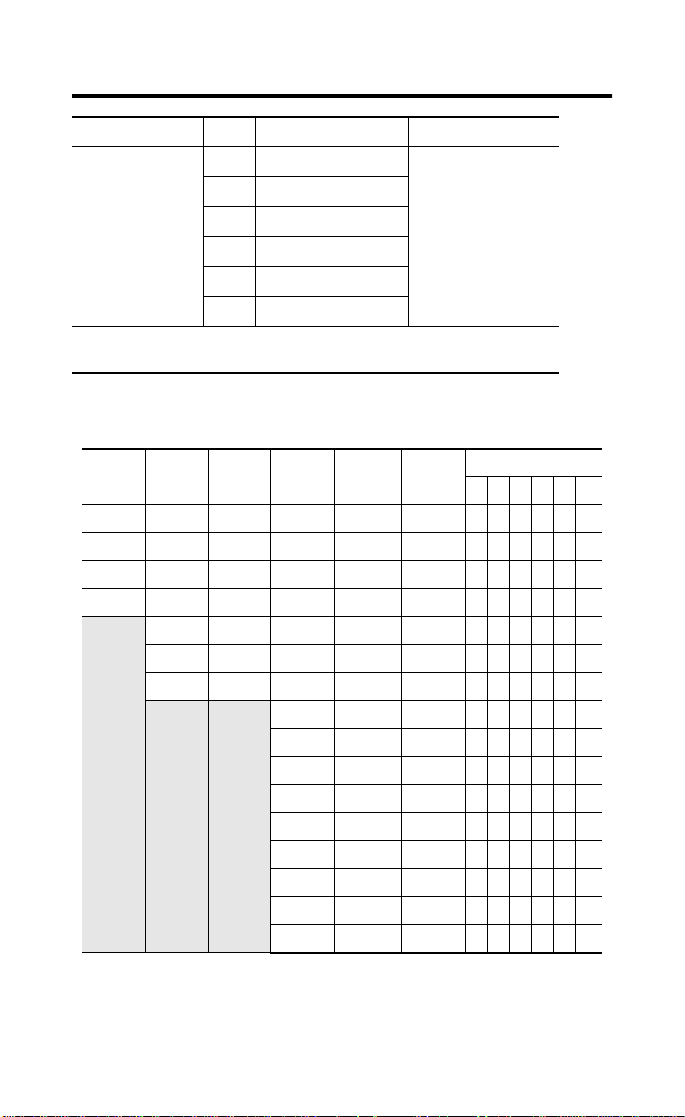
DIP Switch No. Description
3 Rack Address
4 Rack Address
SW1
5 Rack Address
6 Rack Address
See table below.
7 Rack Address
8 Rack Address
Rack Address (6 bit): Position in scanner data mapping.
Starting Quarter: Position in Rack Address with 1/4 rack size data.
Rack addresses are listed in the table below.
1747-SN
Rack
Number
Rack 0 Rack 1 Rack 1 Not Valid Rack 0 Rack 0 0 0 0 0 0 0
Rack 1 Rack 2 Rack 2 Rack 1 Rack 1 Rack 1 0 0 0 0 0 1
Rack 2 Rack 3 Rack 3 Rack 2 Rack 2 Rack 2 0 0 0 0 1 0
Rack 3 Rack 4 Rack 4 Rack 3 Rack 3 Rack 3 0 0 0 0 1 1
1771-SN
Rack
Number
Rack 5 Rack 5 Rack 4 Rack 4 Rack 4 0 0 0 1 0 0
Rack 6 Rack 6 Rack 5 Rack 5 Rack 5 0 0 0 1 0 1
Rack 7 Rack 7 Rack 6 Rack 6 Rack 6 0 0 0 1 1 0
PLC-2
Rack
Number
PLC-5
Rack
Number
Rack 7 Rack 7 Rack 7 0 0 0 1 1 1
Rack 10 Rack 10 Rack 10 0 0 1 0 0 0
Rack 11 Rack 11 Rack 11 0 0 1 0 0 1
Rack 12 Rack 12 Rack 12 0 0 1 0 1 0
Rack 13 Rack 13 Rack 13 0 0 1 0 1 1
Rack 14 Rack 14 Rack 14 0 0 1 1 0 0
Rack 15 Rack 15 Rack 15 0 0 1 1 0 1
Rack 16 Rack 16 Rack 16 0 0 1 1 1 0
Rack 17 Rack 17 Rack 17 0 0 1 1 1 1
PLC5/250
Rack
Number
PLC-3
Rack
Number
SW1 Switch Position
876543
Publication 1791R-IN001A-EN-P - February 2002
Page 7

CompactBlock Distributed I/O on Remote I/O 7
1747-SN
Rack
Number
1771-SN
Rack
Number
PLC-2
Rack
Number
PLC-5
Rack
Number
Rack 20 Rack 20 Rack 20 0 1 0 0 0 0
Rack 21 Rack 21 Rack 21 0 1 0 0 0 1
Rack 22 Rack 22 Rack 22 0 1 0 0 1 0
Rack 23 Rack 23 Rack 23 0 1 0 0 1 1
Rack 24 Rack 24 Rack 24 0 1 0 1 0 0
Rack 25 Rack 25 Rack 25 0 1 0 1 0 1
Rack 26 Rack 26 Rack 26 0 1 0 1 1 0
Rack 27 Rack 27 Rack 27 0 1 0 1 1 1
PLC5/250
Rack
Number
Rack 30 Rack 30 011000
Rack 31 Rack 31 011001
Rack 32 Rack 32 011010
Rack 33 Rack 33 011011
Rack 34 Rack 34 011100
Rack 35 Rack 35 011101
Rack 36 Rack 36 011110
Rack 37 Rack 37 011111
PLC-3
Rack
Number
Rack 40 100000
Rack 41 100001
Rack 42 100010
Rack 43 100011
Rack 44 100100
Rack 45 100101
Rack 46 100110
Rack 47 100111
Rack 50 101000
Rack 51 101001
Rack 52 101010
Rack 53 101011
Rack 54 101100
Rack 55 101101
SW1 Switch Position
876543
Publication 1791R-IN001A-EN-P - February 2002
Page 8
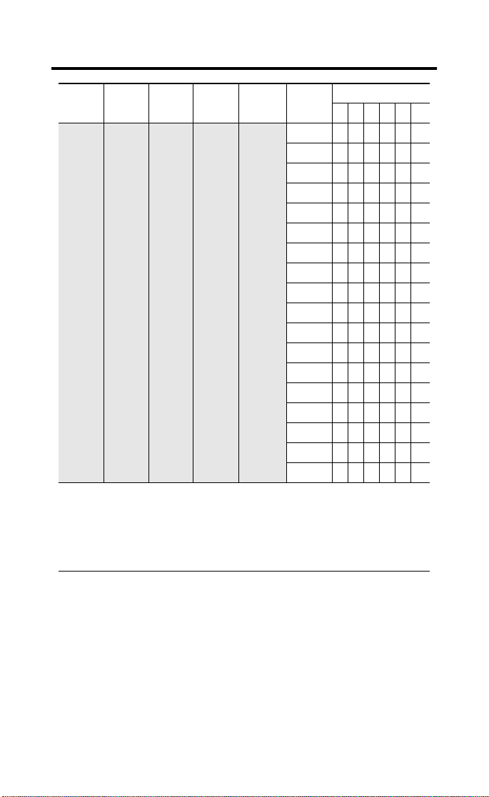
8 CompactBlock Distributed I/O on Remote I/O
1747-SN
Rack
Number
Rack address 77 is an illegal configuration.
PLC-5/11 processors can scan rack 03.
1771-SN
Rack
Number
PLC-2
Rack
Number
PLC-5
Rack
Number
PLC5/250
Rack
Number
PLC5/15 and PLC-5/20 processors can scan racks 01-03.
PLC5/25 and PLC-5/30 processors can scan racks 01-07.
PLC5/40 and PLC-5/40L processors can scan racks 01-17.
PLC5/60 and PLC-5/60L processors can scan racks 01-27.
PLC5/250 processors can scan racks 00-37.
PLC-3
Rack
Number
Rack 56 101110
Rack 57 101111
Rack 60 110000
Rack 61 110001
Rack 62 110010
Rack 63 110011
Rack 64 110100
Rack 65 110101
Rack 66 110110
Rack 67 110111
Rack 70 111000
Rack 71 111001
Rack 72 111010
Rack 73 111011
Rack 74 111100
Rack 75 111101
Rack 76 111110
Not Valid111111
SW1 Switch Position
876543
Publication 1791R-IN001A-EN-P - February 2002
Page 9

CompactBlock Distributed I/O on Remote I/O 9
WARNING
!
DIP
Switch
SW2
No. Description ON OFF
1Comm Rate
2Comm Rate
3 N/A
4 Hold Last State Hold Last State Output Reset
5 Processor
Restart/Lockout
6 Last I/O Last Rack Not Last Rack
7 Filter Speed Setting
8 Filter Speed Setting
00=57.6K 01=115.2K
10=230.4K 11=230.4K
Lockout Restart
00=2ms 10=4ms
01=8ms 11=16ms
Mount the Block(s)
The base and expansion modules mount to a panel or DIN rail which
must be grounded before installing the module(s).
Base Module Mounting
Install the CompactBlock base module on a panel or DIN rail.
When used in a Class I, Division 2, hazardous
location, this equipment must be mounted in a
suitable enclosure with proper wiring method
that complies with the governing electrical
codes.
Panel Mounting
1. Place the module against the panel where you want to mount
it.
2. Drill holes in the panel that are aligned with mounting holes
on the module.
Publication 1791R-IN001A-EN-P - February 2002
Page 10

10 CompactBlock Distributed I/O on Remote I/O
3. Place screws through each of the 2 mounting holes and
tighten until the module is firmly in place.
Base Module
141 mm
5.55 in
Status
Comm
Remote I/O
01234567
Allen-Bradley
01234567
CompactBlock I/O
8 INPUTS / 8 OUTPUTS - DC POWER
1791R-8V8P
41 mm
1.6 in
41673
DIN Rail Mounting
1. Hook top of slot over the DIN Rail.
2. Pull down on the locking lever while pressing the block
against the rail.
Locking Lever
90358
3. Push up on the locking lever to secure the block to the rail
when block is flush against the rail.
Publication 1791R-IN001A-EN-P - February 2002
Page 11

CompactBlock Distributed I/O on Remote I/O 11
ATTENTION
!
Connecting an Expansion Module to a Base Module
Expansion blocks should not be installed when
power is applied to the base.
IMPORTANT
Carefully read the section on I/O images for 1791R
base modules starting on page 19 to change
produce and consume data sizes.
1. Remove the expansion covers from both the base and
expansion modules.
2. Position the expansion block with the proper spacing. See the
illustration below.
Status
Comm
Remote I/O
Base Module Expansion Module
141 mm
5.55 in
01234567
Allen-Bradley
01234567
CompactBlock I/O
8 INPUTS / 8 OUTPUTS - DC POWER
1791R-8V8P
Expansion covers
25 mm
1 in
41 mm
1.6 in
104 mm
4.09 in
41 mm
30358
3. Mount expansion module using panel or DIN rail mounting, as
described in the previous section.
4. Plug the expansion cable into both the base and expansion
modules.
1.6 in
Publication 1791R-IN001A-EN-P - February 2002
Page 12

12 CompactBlock Distributed I/O on Remote I/O
WARNING
!
IMPORTANT
The expansion cable can only be connected to the
modules such that the red stripe on the cable is on
top as shown below.
Red strip must be on top of ribbon cable
01
67
01
Status
Comm
Remote I/O
2345
Allen-Bradley
2345
CompactBlock I/O
1791R-8V8P
8 INPUTS / 8 OUTPUTS - DC POWER
67
30360
5. Replace the expansion covers on both modules.
Connect the Input/Output Wires to the Block
Two sets of VDC+ and GND power pins are located on each terminal
(one for each bank of 8 points) except on the 1791R-4B4P module.
The following figures show the wiring information for both sinking
and sourcing wiring. Input and Output wiring use up to 14AWG
2
) stranded (Cu) with 3/64 inch insulation.
(2mm
Use supply wires suitable for 30°C above
surrounding ambient.
Publication 1791R-IN001A-EN-P - February 2002
Page 13

CompactBlock Distributed I/O on Remote I/O 13
Output Wiring Diagram for 1791R-0B16P and 1791D-0B16PX Modules
Not
Used
+
V
DC
OUT 0 OUT 2
GND
OUT 1 OUT 3
Load
OUT 4
OUT 5 OUT 7
OUT 8OUT 6
OUT 10
V
DC
OUT 9
GND
OUT 12 OUT 14
OUT 11 OUT 15OUT 13
-
Input Wiring Diagram for 1791R-16B0 and 1791D-16B0X Modules
V
DC
IN 0 IN 2
GND
IN 1 IN 3
IN 4
IN 5 IN 7
V
IN 8IN 6
IN 10
DC
IN 9
-
+
IN 12 IN 14
IN 11 IN 15IN 13GND
Wiring Diagram for the 1791R-8B8P Module
V
DC
-
+
IN 0 IN 2
GND
IN 1 IN 3
IN 4
IN 5 IN 7
OUT 0IN 6
OUT 2
V
DC
OUT 1
GND
+
Load
-
OUT 4 OUT 6
OUT 3 OUT 7OUT 5
Not
Used
41669
Not
Used
41671
41672
Publication 1791R-IN001A-EN-P - February 2002
Page 14

14 CompactBlock Distributed I/O on Remote I/O
Wiring Diagram for the 1791R-4B4P Module
V
DC
GND
IN 0 V
IN 1 V
IN 2
DC
DC
DC
IN 3 V
OUT 0V
V
DC
GND
DC
OUT 1
GND
GND GNDOUT 3
OUT 2 GND
Not
Used
+
-
+
-
Load
Wiring Diagram for the 1791R-8V8P Module
V
DC
IN 0 IN 2 OUT 0IN 6
GND GND
IN 1 IN 3
+
-
IN 4
IN 5 IN 7
V
DC
OUT 1
-
+
Output Wiring Diagram for 1791D-0V16PX Modules
V
DC
OUT 0 OUT 2
GND
OUT 1 OUT 3
OUT 4
OUT 5 OUT 7
OUT 8OUT 6
V
DC
GND
OUT 10
OUT 9
OUT 11 OUT 15OUT 13
OUT 2
OUT 4 OUT 6
OUT 3 OUT 7OUT 5
Load
OUT 12 OUT 14
42344
Not
Used
42346
Not
Used
-
Load
+
Publication 1791R-IN001A-EN-P - February 2002
41726
Page 15

CompactBlock Distributed I/O on Remote I/O 15
WARNING
!
Input Wiring Diagram for 1791D-16V0X Modules
V
DC
GND
IN 0 IN 2
IN 1 IN 3
IN 4
IN 5 IN 7
IN 8IN 6
IN 10
IN 9
IN 12 IN 14
IN 11 IN 15IN 13
V
DC
GND
Not
Used
+
-
41670
Connect the Remote I/O Terminal Connector
Refer to the following information when connecting the Remote I/O
terminal connector to the 1791R block I/O.
If you connect or disconnect the serial cable
with power applied to this module or the serial
device on the other end of the cable, an
electrical arc can occur. This could cause an
explosion in hazardous location installations. Be
sure that power is removed or the area is
nonhazardous before proceeding.
1. Connect the Remote I/O female 3-pin connector to the
terminal connector as shown below.
Status
Comm
Remote I/O
RIO
0
1
2
3
4
5
Allen-Bradley
6
7
0
1
2
3
4
5
6
7
Compact
8 INPUTS / 8 OUTPUTS . DC POWER
Block I/O
1791R-8V8P
43105
Publication 1791R-IN001A-EN-P - February 2002
Page 16

16 CompactBlock Distributed I/O on Remote I/O
2. Connect the terminal connector to the Block. Use the side
screws on the terminal connector to fasten it to the Block.
Pin
Number:
1 blue Line 1
2 shield Shield
3 clear Line 2
Wire
Color:
Description:
Select Termination for the Module
The terminator resistor is provided in the module. Use the DIP
switches to select termination for the module. See below.
Line 1
SW1
SW2
Line 2
82 ohm
Switch SW1 SW2
ON Terminator on *1 Terminator on **2
OFF No Terminator No Terminator
* 1 at baud rate 230.4KBPS.
**2 at baud rate 57.6KBPS or 115.2KBPS.
150 ohm
Base Module to Expansion Interface
The base module is linked to the expansion module with an 8-bit
parallel bus, control lines, Vcc and ground connections, a
reset/initialization line, and an expansion presence line. The 8-bit bus
is multiplexed so that 16 bits of data (1 for each I/O point) can be
transmitted/received with two transfers. The reset/initialization line is
used during initialization of the module. The presence line is used for
the detection of an expansion module at power up and for a period
of each data transfer. Module ID is read over this bus at power up.
Publication 1791R-IN001A-EN-P - February 2002
Page 17

CompactBlock Distributed I/O on Remote I/O 17
WARNING
!
1791R modules supply expansion power via expansion bus as
follows:
Expansion power voltage 5Vdc
Expansion power current 100mA
Connect Power to the Module
To apply power to the 1791R module, refer to the illustration below.
Module power
connector
COM
GND
+24V
Pin Number Name
1 Com (24V dc return)
2 Gnd (Field ground)
3+24V dc
43108
Remove the Terminal Block
When you connect or disconnect the Removable
Terminal Block (RTB) with field side power
applied, an electrical arc can occur. This could
cause an explosion in hazardous location
installations.
Be sure that power is removed or the area is
nonhazardous before proceeding.
Follow the directions below to remove the CompactBlock terminal
block.
1. Unscrew the two retaining screws on the side of the terminal
block.
Publication 1791R-IN001A-EN-P - February 2002
Page 18

18 CompactBlock Distributed I/O on Remote I/O
2. Lift the terminal block out of the base.
Retaining Screw
VDC
IN0
IN2
Retaining Screw
Remote I/O
RIO
Comm
Status
IN4
IN1
GND
IN6
IN3
IN5
VDC
IN8
IN7
0
1
2
3
4
5
IN10
IN12
GND
IN9
IN14
IN11
6
7
0
Not
IN13
Used
IN15
1
2
3
4
5
6
7
43106
Insert the Terminal Block
Follow the directions below to insert the CompactBlock terminal
block.
1. Insert the terminal block by aligning it and pushing it back
until it rests against the back of the module.
2. Tighten the screws on each side of the terminal block until the
terminal block is firmly in place.
Publication 1791R-IN001A-EN-P - February 2002
Page 19

CompactBlock Distributed I/O on Remote I/O 19
Communicate With the 1791R Module
Determine the Baud Rate for Your Remote I/O Connection
Use the DIP switches to set the baud rate before you power up the
module.
Refer to the following table for baud rate specifications.
Baud Rate Cable Length
57.6KBPS 3048m
115.2KBPS 1524m
230.4KBPS 762m
I/O Image Word/Bit Definitions
The smallest portion of a scanners I/O image that can be allocated to
a single RIO device is two logical groups or 1/4 logical rack. A
device’s starting group must begin at even group numbers (0, 2, 4, or
6). See your scanner documentation for further details.
All combinations of 1791R base and expansion modules will fit in the
space allocated by 1/4 logical rack.
I/O images for 1791R base modules follow.
16B0
17 16 15 14 13 12 11 10 7 6 5 4 3 2 1 0
Input
ImageIn15In14In13In12In11In10In 9In 8In 7In 6
Input
Image
Output
Image
Output
Image
Reserved
Reserved
Reserved
In 5In 4In 3In 2In 1In
Publication 1791R-IN001A-EN-P - February 2002
0
Page 20

20 CompactBlock Distributed I/O on Remote I/O
0B16P
17 16 15 14 13 12 11 10 7 6 5 4 3 2 1 0
Input
Image
Input
Image
Output
ImageO 15O 14O 13O 12O11O 10O 9O 8O 7O 6O 5O 4O 3O 2
Output
Image
8B8P/8V8P
17 16 15 14 13 12 11 10 7 6 5 4 3 2 1 0
Input
Image
Input
Image
Output
Image
Output
Image
Reserved In 7In 6In 5In 4In 3In 2In 1In
Reserved O 7O 6O 5O 4O 3O 2O 1O
4B4P
17 16 15 14 13 12 11 10 7 6 5 4 3 2 1 0
Input
Image
Input
Image
Output
Image
Output
Image
Reserved
Reserved
Reserved
Reserved
Reserved
Reserved In 3In 2In 1In
Reserved
Reserved O 3O 2O 1O
Reserved
O 1O
0
0
0
0
0
Publication 1791R-IN001A-EN-P - February 2002
Page 21

CompactBlock Distributed I/O on Remote I/O 21
The following examples are for 1791R base modules with expansion
modules.
0B16P with 0B16PX
17 16 15 14 13 12 11 10 7 6 5 4 3 2 1 0
Input
Image
Input
Image
Output
ImageO 15O 14O 13O 12O 11O 10O 9O 8O 7
EX
EX
EX
EX
Output
Image
O
O
15
O
14
13
EX
O
O
12
11
16B0 with 16BOX
17 16 15 14 13 12 11 10 7 6 5 4 3 2 1 0
Input
ImageIn15In14In13In12In11In10In9In8In7In6In5In4In3In2In1In0
Ex
EX
EX
EX
Input
Image
Output
Image
Output
Image
In
In
15
In
14
13
EX
In
In
12
11
Reserved
Reserved
O 6O 5O 4O 3O 2O 1O
EX
EX
EX
EX
EX
EX
EX
O
O
O
O
10
9
EX
EX
In
In
10
9
O
8
7
6
EX
EX
EX
In
In
In
8
7
6
EX
O
O
O
5
4
3
EX
EX
EX
In
In
In
5
4
3
0
EX
EX
EX
O
O
O
2
1
0
EX
EX
EX
In
In
In
2
1
0
Reserved
Reserved
16B0 with 0B16X or 0B16P with 16BOX
17 16 15 14 13 12 11 10 7 6 5 4 3 2 1 0
Input
ImageIn15In14In13In12In11In10In9In8In7In6In5In4In3In2In1In0
Input
Image
Output
ImageO 15O 14O 13O 12O 11O 10O 9O 8O 7O 6O 5
Output
Image
Reserved
O 4O 3O 2O 1O
Reserved
Publication 1791R-IN001A-EN-P - February 2002
0
Page 22

22 CompactBlock Distributed I/O on Remote I/O
8B8P with 16BOX or 8V8P with 16VOX
17 16 15 14 13 12 11 10 7 6 5 4 3 2 1 0
EX
EX
EX
EX
EX
EX
EX
Input
In
In
In
In
In
Image
Input
Image
Output
Image
Output
Image
7
6
5
4
Reserved
Reserved O 7O 6O 5O 4O 3O 2O 1O
In
3
2
8B8P with 0B16PX or 8V8P with 0V16PX
17 16 15 14 13 12 11 10 7 6 5 4 3 2 1 0
Input
Image
Input
Image
Output
Image
Output
Image
EX
EX
O
O
7
6
Reserved In 7In 6In 5In 4In 3In 2In 1In
EX
EX
EX
O
O
5
4
EX
O
O
3
2
Reserved
4B4P with 16BOX
17 16 15 14 13 12 11 10 7 6 5 4 3 2 1 0
EX
EX
EX
EX
EX
Input
Image
Input
Image
Output
Image
Output
Image
In
In
In
11
10
In
9
8
EX
In
In
7
6
Reserved
Reserved O 3O 2O 1O
In
1
EX
O
1
EX
In
5
EX
In 7In 6In 5In 4In 3In 2In 1In
In
0
Ex
In
15
Reserved
Reserved
EX
O 7O 6O 5O 4O 3O 2O 1O
O
0
EX
O
15
EX
EX
In
In
4
3
Reserved
0
EX
EX
EX
EX
EX
EX
In
In
In
14
In
13
12
11
EX
In
In
In
10
9
8
0
0
0
EX
EX
EX
EX
EX
EX
O
O
O
13
EX
In
1
O
12
11
EX
In3In2In1In
In
0
Ex
In
15
14
EX
In
2
EX
O
O
O
10
9
8
0
E
EX
EX
X
In
In
In
13
12
14
0
Publication 1791R-IN001A-EN-P - February 2002
Page 23

CompactBlock Distributed I/O on Remote I/O 23
4B4P with 0B16PX
17 16 15 14 13 12 11 10 7 6 5 4 3 2 1 0
EX
O
7
Reserved
EX
O
6
Reserved
EX
O
5
Reserved
EX
O
4
In 3In 2In 1In
EX
EX
EX
EX
O
1
O 3O 2O 1O
O
0
EX
O
15
EX
EX
O
O
14
13
O
O
3
2
Input
Image
Input
Image
Output
Image
Output
Image
EX
EX
EX
O
O
11
10
EX
O
O
9
8
Troubleshoot with the Indicators
The 1791R I/O module has the following indicators:
• Status indicator - base only
• Comm indicator - base only
• I/O status indicators - base and expansion
Status Indicator
Indication: Status:
Off No power
Red Hardware or software error, power is low
Green Normal operation
Flashing Red Comm failure 1*
Flashing Red/Orange Expansion error
*1 Comm fail = communication cable disconnected, 100ms between valid
frames, no more than 255 valid frames between valid frames addressed to
module, 20ms idle time exceeded.
**2 COMM and STATUS will alternately flash when processor restart lockout is
selected, a fault has occurred and the processor is communicating with he
module.
0
0
EX
O
12
Publication 1791R-IN001A-EN-P - February 2002
Page 24

24 CompactBlock Distributed I/O on Remote I/O
Comm Status Indicator
Indication: Status:
Off Communication not established
Green Communication established
Flashing Green Processor in Program mode
I/O Status Indicators
Function: LED Color: Module
Illumination:
Outputs Each output:
Yellow
Inputs Each Input:
Yellow
None
Yellow
None
Yellow
Specifications
Sinking or Sourcing Input Specifications
Inputs per block groups of 4 or 8
Off-state Voltage 5V dc maximum
On-state Voltage 30V dc @ 40°C maximum
Off-state Current 1.5mA minimum
On-state Current 11mA @ 30V dc maximum
Sinking or Sourcing Output Specifications
Outputs per block groups of 4 or 8
On-state Voltage Range 10 - 30V dc
On-state Voltage Drop 0.5V dc @ rated current
On-state Current 0.5A maximum
Off-state Leakage 1.0mA maximum
Module Current (per output) 0.5A maximum
Surge Current - for 10 mS
repeatable every 2 S
25V dc @ 60°C maximum
10V dc minimum
2mA @ 10V dc minimum
1.0A maximum
Condition:
Output not energized
Output energized
No valid input
Val i d i nput
Publication 1791R-IN001A-EN-P - February 2002
Page 25

CompactBlock Distributed I/O on Remote I/O 25
Sinking or Sourcing Output Specifications (continued)
Indicators Status - red/green/orange
Communication Rate 57.6Kbps @ 3048m (10000ft)
General Specifications
Isolation
Auxiliary I/O power to RIO
I/O group-to-group
I/O group-to-RIO
Isolation
Auxiliary I/O power to RIO
I/O group-to-group
I/O group-to-RIO
RIO Power: Voltage
Current
Expansion Power: Voltage
Auxiliary Power Inputs: Voltage
Current
Auxiliary Power Outputs: Voltage
Base Module Dimensions 150mm X 50mm X 38mm
Expansion Module Dimensions 115mm X 50mm X 38mm
Field Wiring Tightening Torque 5-7lb-in. (0.5-0.6 Nm)
Operating Temperature IEC 60068-2-1 (Test Ad, Operating Cold),
Storage Temperature IEC 60068-2-1 (Test Ab, Un-packaged Non-operating
Relative Humidity IEC 60068-2-30 (Test Db, Un-packaged
Shock IEC60068-2-27 (Test Ea, Unpackaged Shock):
Current
Current
Comm - green
I/O - yellow
115.2Kbps @ 1524m (5000ft)
230.4Kbps @ 762m (2500ft)
Type tested to 500V ac for 60 seconds
Type tested to 500V ac for 60 seconds
Type tested to 500V ac for 60 seconds
Type tested to 500V ac for 60 seconds
Type tested to 500V ac for 60 seconds
Type tested to 500V ac for 60 seconds
18 - 26.4V dc
250mA maximum (with expansion)
5V dc
100mA
10-30V dc
88mA each group of 8
10-30V dc
4A each group of 8
5.91in X 1.97in X 1.5in
4.4in X 1.97in X 1.5in
IEC 60068-2-2 (Test Bd, Operating Dry Heat),
IEC 60068-2-14 (Test Nb, Operating Thermal Shock):
0 to 60°C (32 to 140°F)
Cold),
IEC 60068-2-2 (Test Bb, Un-packaged Non-operating
Dry Heat),
IEC 60068-2-14 (Test Na, Un-packaged
Non-operating Thermal Shock):
–40 to 85°C (–40 to 185°F)
Non-operating Damp Heat):
5-95% non-condensing
Operating 30g
Non-operating 50g
Publication 1791R-IN001A-EN-P - February 2002
Page 26

26 CompactBlock Distributed I/O on Remote I/O
General Specifications (continued)
Vibration IEC60068-2-6 (Test Fc, Operating):
Conductors Wire Size
Category
ESD Immunity IEC 61000-4-2:
Radiated RF Immunity IEC 61000-4-3:
EFT/B Immunity IEC 61000-4-4:
Surge Transient Immunity IEC 61000-4-5:
Conducted RF Immunity IEC 61000-4-6:
Emissions CSPR 11:
Certifications:
(when product is marked)
Enclosure Meets IP20
5g @ 10-500Hz
2
14 gauge (2mm
3/64 inch insulation maximum
1, 2
2
6kV contact discharge
8kV air discharge
10V/m with 1kHz sine-wave 80%AM from 80MHz to
1000MHz
10V/m with 200Hz 50% Pulse 100%AM at 900Mhz
±2kV at 5kHz on signal ports
±2kV at 5kHz on communications ports
1kV line-line(DM) and ±2kV line-earth(CM) on
±
signal ports
2kV line-earth(CM) on shielded ports
±
10Vrms with 1kHz sine-wave 80%AM from 150kHz
to 80MHz
) stranded maximum
Group 1, Class A
c-UL-us UL Listed Industrial Control Equipment,
certified for US and Canada
c-UL-us UL Listed for Class I, Division 2 Group
A,B,C,D Hazardous Locations, certified for
U.S. and Canada
3
CE
Directive, compliant with:
C-Tick
compliant with:
European Union 89/336/EEC EMC
EN 50081-2; Industrial Emissions
EN 50082-2; Industrial Immunity
EN 61326; Meas./Control/Lab., Industrial
Requirements
61000-6-2; Industrial Immunity
3
Australian Radiocommunications Act,
AS/NZS 2064; Industrial Emissions
1. You use this conductor category information for planning conductor routing as
described in the system level installation manual.
2. See publication 1770-4.1, “Programmable Controller Wiring and Grounding
Guidelines.”
3. See the Product Certification link at www.ab.com for Declarations of Conformity,
Certificates, and other certification details.
Publication 1791R-IN001A-EN-P - February 2002
Page 27

CompactBlock Distributed I/O on Remote I/O 27
IMPORTANT
Input and output wiring must be in accordance
with Class 1, Division 2 wiring methods and in
accordance with the authority having jurisdiction.
Hazardous Location Approval
The following information applies when operating
this equipment in hazardous locations:
Products marked “CL I, DIV 2, GP A, B, C, D” are suitable
for use in Class I Division 2 G roups A, B, C, D, Hazardous
Locations and nonhazard ous locations only. Each product
is supplied with markings on th e rating nameplate
indicating the hazardous l ocation temperature code.
When combining products with in a system, the most
adverse temperature co de (lowest “T” number) may be
used to help determine the ove rall temperature code of
the system. Combinations of equipment in your system
are subject to inves tigation by the local Authority Having
Jurisdiction at the time of i nstallation.
EXPLOSION HAZARD
WARNING
!
• Do n ot disconnect
equipment unless
power has been
removed or the
area is known to be
nonhazardous.
• Do n ot disconnect
connections to this
equipment unless
power has been
removed or the
area is known to be
nonhazardous.
Secure any external
connections that
mate to this
equipment by using
screws, sliding
latches, threaded
connectors, or other
means provided
with this product.
• Substitution of
components may
impair suitability
for Class I, Division
2.
• If thi s product
contains batteries,
they must only be
changed in an area
known to be
nonhazardous.
Informations sur l’utilisation de cet équipement en
environnements dangereux :
Les produits marqués "CL I, D IV 2, GP A, B, C, D" ne
conviennent qu’à une utilisation en env ironnements de
Classe I Division 2 Groupes A, B, C, D dang ereux et non
dangereux. Chaque produit es t livré avec des marquages sur
sa plaque d’identification qui indiq uent le code de
température pour les environnem ents dangereux. Lorsque
plusieurs produits sont combin és dans un système, le code
de température le plus déf avorable (code de température le
plus faible) peut être utilisé pour déterminer le code de
température global du systèm e. Les combinaisons
d’équipements dans le systèm e sont sujettes à inspection par
les autorités locales qualifiées au moment d e l’installation.
RISQUE D’E XPLOSION
AVERTISSEMENT
!
• Couper le cour ant ou
s’assurer que
l’environnement est
classé non
dangereux avant de
débrancher
l'équipement.
• Couper le cour ant ou
s'assurer que
l’environnement est
classé non
dangereux avant de
débrancher les
connecteurs. Fixer
tous les connecteurs
externes reliés à cet
équipement à l'aide
de vis, loquets
coulissants,
connecteurs filetés
ou autres moyens
fournis avec ce
produit.
• La subst itution de
composants peut
rendre cet
équipement inadapté
à une utilisation en
environnement de
Classe I, Division 2.
• S’assurer que
l’environnement est
classé non
dangereux avant de
changer les piles.
Publication 1791R-IN001A-EN-P - February 2002
Page 28

CompactBlock is a trademark of Rockwell Automation, Allen-Bradley, Inc.
Publication 1791R-IN001A-EN-P - February 2002 PN 957626-63
Supersedes Pub lication 1791D-5.42 - Ap ril 1999 Copyright © 2002 Rockwell A utomation. All rights reserv ed. Printed in the U.S.A.
 Loading...