

Page 1

Installation Instructions
Compact
Block
Distributed I/O on
PROFIBUS DP Series D
(Cat. No. 1791P-16B0, -0B16P, -8B8P, -4B4P, -8V8P)
1791P CompactBlock™ I/O modules are stand-alone 24V dc Block
I/O products that communicate via a PROFIBUS DP link. Each PROFIBUS
DP node consists of either one base module or one base module and one
expansion module. Any expansion module can be coupled with any base
module. CompactBlock 1791P consists of only base modules. The expansion
modules are part of the CompactBlock 1791D family of products.
CompactBlock PROFIBUS DP modules must be installed in a secondary
enclosure. Base modules are equipped with 8 to 16 points.
CompactBlock PROFIBUS DP provides sinking and sourcing inputs and
outputs. Sinking inputs are 24V dc IEC Type 3 compatible. Self-protected
24V dc outputs can provide up to 0.5 amp each.
Important User Information
Because of the variety of uses for the products described in this publication,
those responsible for the application and use of these products must satisfy
themselves that all necessary steps have been taken to assure that each
application and use meets all performance and safety requirements, including
any applicable laws, regulations, codes and standards. In no event will
Rockwell Automation be responsible or liable for indirect or consequential
damage resulting from the use or application of these products.
Publication 1791P-IN002B-EN-P - October 2003
Page 2

2 CompactBlock Distributed I/O on PROFIBUS DP Series D
Any illustrations, charts, sample programs, and layout examples shown in this
publication are intended solely for purposes of example. Since there are many
variables and requirements associated with any particular installation,
Rockwell Automation does not assume responsibility or liability (to include
intellectual property liability) for actual use based upon the examples shown in
this publication.
Allen-Bradley publication SGI-1.1, Safety Guidelines for the Application,
Installation and Maintenance of Solid-State Control (available from your local
Rockwell Automation office), describes some important differences between
solid-state equipment and electromechanical devices that should be taken into
consideration when applying products such as those described in this
publication.
Reproduction of the contents of this copyrighted publication, in whole or
part, without written permission of Rockwell Automation, is prohibited.
Throughout this publication, notes may be used to make you aware of safety
considerations. The following annotations and their accompanying statements
help you to identify a potential hazard, avoid a potential hazard, and recognize
the consequences of a potential hazard:
WARNING
ATTENTION
IMPORTANT
Publication
Identifies information about practices or circumstances
that can cause an explosion in a hazardous environment,
which may lead to personal injury or death, property
damage, or economic loss.
Identifies information about practices or circumstances
that can lead to personal injury or death, property
damage or economic loss.
Identifies information that is critical for successful
application and understanding of the product.
1791P-IN002B-EN-P - October 2003
Page 3

ATTENTION
CompactBlock Distributed I/O on PROFIBUS DP Series D 3
Environment and Enclosure
This equipment is intended for use in a Pollution Degree
2 industrial environment, in overvoltage Category II
applications (as defined in IEC publication 60664-1), at
altitudes up to 2000 meters without derating.
This equipment is considered Group 1, Class A industrial
equipment according to IEC/CISPR Publication 11.
Without appropriate precautions, there may be potential
difficulties ensuring electromagnetic compatibility in
other environments due to conducted as well as radiated
disturbance.
This equipment is supplied as "enclosed" equipment. It
should not require additional system enclosure when
used in locations consistent with the enclosure type
ratings stated in the Specifications section of this
publication. Subsequent sections of this publication may
contain additional information regarding specific
enclosure type ratings, beyond what this product
provides, that are required to comply with certain
product safety certifications.
See NEMA Standards publication 250 and IEC
publication 60529, as applicable, for explanations of the
degrees of protection provided by different types of
enclosure. Also, see the appropriate sections in this
publication, as well as the Allen-Bradley publication
1770-4.1 ("Industrial Automation Wiring and Grounding
Guidelines"), for additional installation requirements
pertaining to this equipment.
Publication
1791P-IN002B-EN-P - October 2003
Page 4

4 CompactBlock Distributed I/O on PROFIBUS DP Series D
Installing CompactBlock I/O
Follow these steps, to install the 1791P I/O module:
1. Set the Station Address on the Base Module.
2. Mount the Block(s).
3. Connect the Input/Output Wires to the Block.
4. Connect the PROFIBUS DP connector.
5. Select termination for the module.
6. Connect power to the module.
7. Remove the terminal block.
8. Insert the terminal block.
9. Communicate with the 1791P Module.
These steps are explained in detail in the following procedures.
Publication
1791P-IN002B-EN-P - October 2003
Page 5

CompactBlock Distributed I/O on PROFIBUS DP Series D 5
Preventing Electrostatic Discharge
This equipment is sensitive to electrostatic discharge,
which can cause internal damage and affect normal
operation. Follow these guidelines when you handle
this equipment:
• Touch a grounded object to discharge potential
ATTENTION
static.
• Wear an approved grounding wriststrap.
• Do not touch connectors or pins on component
boards.
• Do not touch circuit components inside the
equipment.
• If available, use a static-safe workstation.
• When not in use, store the equipment in
appropriate static-safe packaging.
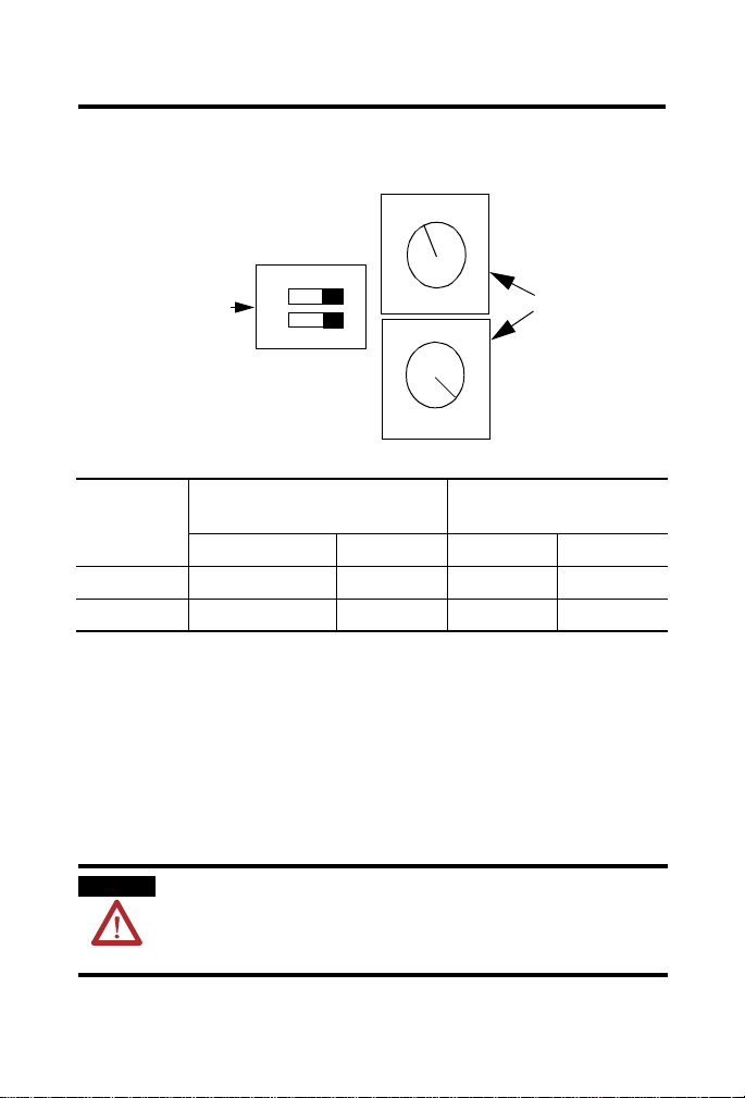
Set the Station Address on the Base Module
To set the station address, lift the door containing the status LEDs on the top
left side of the module. Adjust the switches located behind the door.
The rotary switches can be set between 00 and 99. Use the adjusting tool
provided in the package, or a small bladed screwdriver to rotate the switches.
The DIP switches are used for addresses between 100 and 125.
Publication
1791P-IN002B-EN-P - October 2003
Page 6
6 CompactBlock Distributed I/O on PROFIBUS DP Series D
The switches are read at module power up only.
View when looking into module.
3
2
10’s
1
4
100’s
DIP Switches
(100-125)
ON
0
9
1 2
1
0
9
1’s
5
6
8
7
3
2
4
5
6
8
7
Rotary Switches
Example: Node
Address is set at 26
(00-99)
43112
DIP Switches
Address
Position 1 Position 2 10’s 1’s
0-99 0 0 0-9 0-9
100-125 1 0 0-2 0-5
100’s
Rotary Switches
Mount the Block(s)
The base and expansion modules mount to a panel or DIN rail, which must
be grounded before installing the module(s).
Base Module Mounting
You c a n install t h e Compact Block base module on a panel or DIN rail.
WARNING
Publication
1791P-IN002B-EN-P - October 2003
When used in a Class I, Division 2, hazardous
location, this equipment must be mounted in a suitable
enclosure with proper wiring method that complies
with the governing electrical codes.
Page 7
CompactBlock Distributed I/O on PROFIBUS DP Series D 7
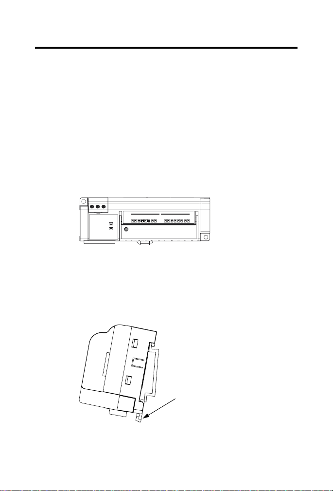
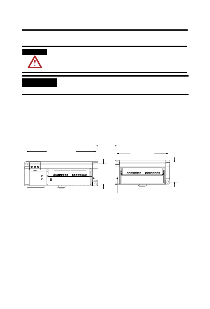
Panel Mounting
1. Place the module against the panel where you want to mount it.
2. Drill holes in the panel that are aligned with mounting holes on the
module.
3. Place screws through each of the 2 mounting holes and tighten until
the module is firmly in place.
Base Module
141 mm
5.55 in
Module
Status
Network
Status
Profibus DP
01234567
Allen-Bradley
01234567
CompactBlock I/O
8 INPUTS / 8 OUTPUTS - DC POWER
1791P-8V8P
41 mm
1.6 in
43115
DIN Rail Mounting
1. Hook top of slot over the DIN Rail.
2. Pull down on the locking lever while pressing the block against the
rail.
Locking Lever
90358
3. Push up on the locking lever to secure the block to the rail when block
is flush against the rail.
Publication
1791P-IN002B-EN-P - October 2003
Page 8
8 CompactBlock Distributed I/O on PROFIBUS DP Series D
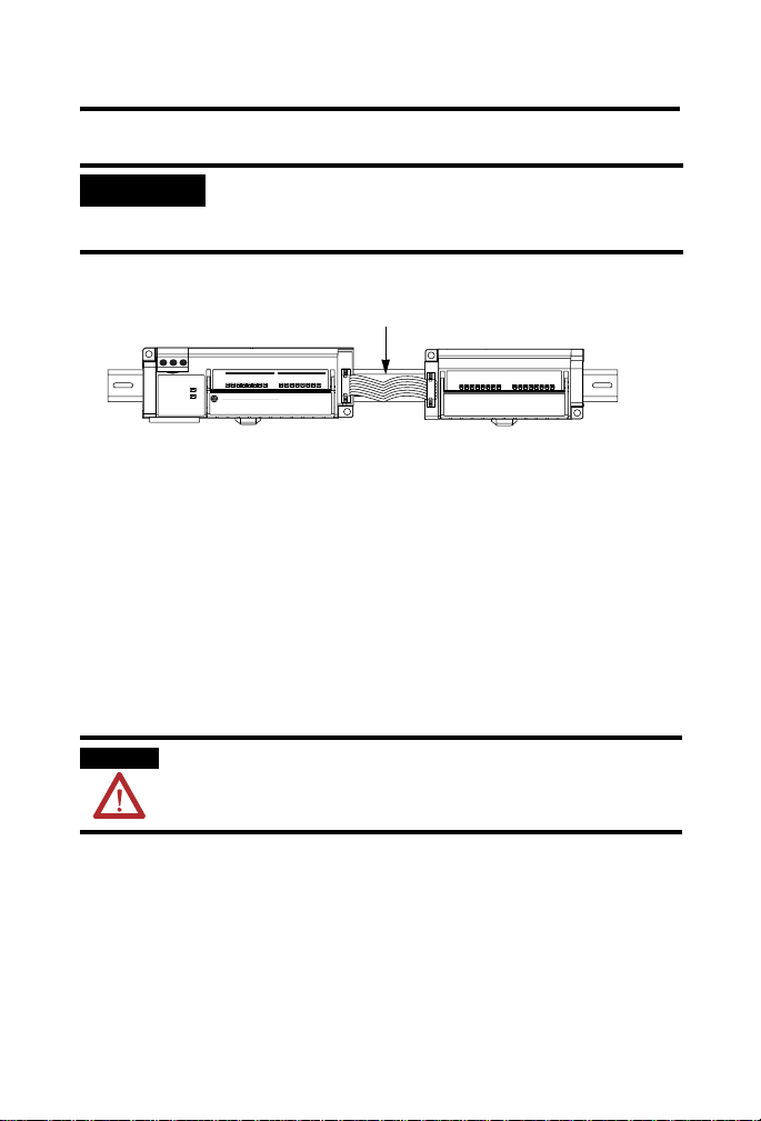
Connecting an Expansion Module to a Base Module
ATTENTION
Expansion blocks should not be installed when power
is applied to the base.
IMPORTANT
Carefully read the section “Word/Bit Definitions” on
page 18 to change produce and consume data sizes.
1. Remove the expansion covers from both the base and expansion
modules.
2. Position the expansion block with the proper spacing. See the
illustration below.
Module
Status
Network
Status
Profibus DP
Base Module Expansion Module
141 mm
5.55 in
01234567
01234567
Allen-Bradley
CompactBlock I/O
8 INPUTS / 8 OUTPUTS - DC POWER
25 mm
1 in
41 mm
1.6 in
1791P-8V8P
Expansion covers
104 mm
4.09 in
3. Mount expansion module using panel or DIN rail mounting, as
described in the previous section.
41 mm
1.6 in
43116
Publication
1791P-IN002B-EN-P - October 2003
Page 9
CompactBlock Distributed I/O on PROFIBUS DP Series D 9
4. Plug the expansion cable into both the base and expansion modules.
IMPORTANT
The expansion cable can only be connected to the
modules such that the red stripe on the cable is on top as
shown below.
Red strip must be on top of ribbon cable.
01
67
01
Module
Status
Network
Status
Profibus DP
2345
Allen-Bradley
2345
CompactBlock I/O
1791P-8V8P
8 INPUTS / 8 OUTPUTS - DC POWER
67
43117
5. Replace the expansion covers on both modules.
Connect the Input/Output Wires to the Block
Two sets of VDC+ and GND power pins are located on each terminal (one
for each bank of 8 points) except on the 1791P-4B4P module. The following
figures show the wiring information for both sinking and sourcing wiring.
Input and Output wiring use up to 14AWG (2mm
inch insulation.
WARNING
Use supply wires suitable for 30°C above surrounding
ambient.
2
) stranded (Cu) with 3/64
Publication
1791P-IN002B-EN-P - October 2003
Page 10
10 CompactBlock Distributed I/O on PROFIBUS DP Series D
Output Wiring Diagram for 1791P-0B16P and 1791D-0B16PX
Modules
V
DC
OUT 0 OUT 2
OUT 4
OUT 8OUT 6
OUT 10
V
DC
OUT 12 OUT 14
Not
Used
GND
OUT 1 OUT 3
OUT 5 OUT 7
GND
OUT 9
OUT 11 OUT 15OUT 13
+
Load
-
41669
Input Wiring Diagram for 1791P-16B0 and 1791D-16B0X Modules
V
DC
GND
IN 0 IN 2
IN 1 IN 3
IN 4
IN 5 IN 7
V
IN 8IN 6
IN 10
DC
IN 9
IN 12 IN 14
IN 11 IN 15IN 13GND
-
+
Not
Used
41671
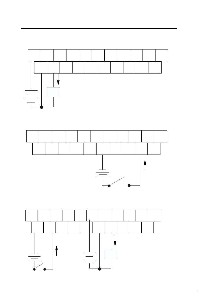
Wiring Diagram for the 1791P-8B8P Module
V
DC
GND
IN 0 IN 2
IN 1 IN 3
IN 4
IN 5 IN 7
OUT 0IN 6
OUT 2
V
DC
GND
OUT 1
OUT 4 OUT 6
OUT 3 OUT 7OUT 5
Not
Used
-
+
Publication
+
Load
-
1791P-IN002B-EN-P - October 2003
41672
Page 11

CompactBlock Distributed I/O on PROFIBUS DP Series D 11
Wiring Diagram for the 1791P-4B4P Module
V
DC
IN 0 V
IN 2
DC
DC
OUT 0V
V
DC
GND
OUT 2 GND
Not
Used
GND
IN 1 V
IN 3 V
DC
+
-
GND
OUT 1
DC
+
GND GNDOUT 3
Load
-
Wiring Diagram for the 1791P-8V8P Module
V
IN 0 IN 2 OUT 0IN 6
DC
GND GND
IN 1 IN 3
+
-
IN 4
IN 5 IN 7
OUT 2
V
DC
OUT 1
-
OUT 4 OUT 6
OUT 3 OUT 7OUT 5
Load
+
Output Wiring Diagram for 1791D-0V16PX Modules
OUT 0 OUT 2
V
DC
GND
OUT 1 OUT 3
OUT 4
OUT 5 OUT 7
OUT 8OUT 6
OUT 10
V
DC
GND
OUT 9
OUT 12 OUT 14
OUT 11 OUT 15OUT 13
Not
Used
42344
Not
Used
42346
-
Load
+
Publication
1791P-IN002B-EN-P - October 2003
41726
Page 12

12 CompactBlock Distributed I/O on PROFIBUS DP Series D
Input Wiring Diagram for 1791D-16V0X Modules
V
DC
IN 0 IN 2
GND
IN 1 IN 3
IN 4
IN 5 IN 7
IN 8IN 6
IN 10
V
DC
GND
IN 9
IN 12 IN 14
IN 11 IN 15IN 13
Not
Used
+
-
41670
Connect the PROFIBUS DP Terminal Connector
Refer to the following information when connecting the PROFIBUS DP
terminal connector to the 1791P block I/O.
WARNING
If you connect or disconnect the PROFIBUS cable
with power applied to this module or any device on
the network, an electrical arc can occur. This could
cause an explosion in hazardous location installations.
Be sure that power is removed or the area is
nonhazardous before proceeding.
Publication
1791P-IN002B-EN-P - October 2003
Page 13

CompactBlock Distributed I/O on PROFIBUS DP Series D 13
1. Connect the PROFIBUS DP female 9-pin D-sub connector to the
terminal connector as shown below.
Module
Status
Network
Status
Profibus DP
Profibus DP
Allen-Bradley
0
1
2
3
4
5
6
7
0
1
2
3
4
5
6
7
Compact
8 INPUTS / 8 OUTPUTS . DC POWER
Block I/O
1791P-8V8P
31337-m
2. Connect the terminal connector to the Block. Use the side screws on
the terminal connector to fasten it to the Block.
Pin
Name: Description:
Number:
1 shield Shield, Protective Ground
2 M24V Minus 24V Output Voltage (Not used)
3 RxD/TxD-P Receive/Transmit-Data-P
4 CNTR-P Control-p
5 DGND Data Ground
6 VP Voltage-Plus
7 P24V Plus 24V Output Voltage (Not used)
8 RxD/TxD-N Receive/Transmit-Data-N
9 CNTR-N Control-N (Not used)
Publication
1791P-IN002B-EN-P - October 2003
Page 14

14 CompactBlock Distributed I/O on PROFIBUS DP Series D
Select Termination for the Module
The terminator resistor is provided in the connector. Use the DIP switches in
the connector to select termination for the module. Refer to the illustration
below.
VP (6)
390 ohm
SW in the connector
RxD/TxD-P (3)
RxD/TxD-N (8)
DGND (5)
220 ohm
390 ohm
Switch SW in the Connector
ON Terminator Connector
OFF No Terminator
43109
Base Module to Expansion Interface
The base module is linked to the expansion module with an 8-bit parallel bus,
control lines, Vcc and ground connections, a reset/initialization line, and an
expansion presence line. The 8-bit bus is multiplexed so that 16 bits of data (1
for each I/O point) can be transmitted/received with two transfers. The
reset/initialization line is used during initialization of the module. The
presence line is used for the detection of an expansion module at power up
and for a period of each data transfer. Module ID is read over this bus at
power up.
1791P modules supply expansion power via expansion bus as follows:
Expansion power voltage 5Vdc
Expansion power current 100mA
Publication
1791P-IN002B-EN-P - October 2003
Page 15

CompactBlock Distributed I/O on PROFIBUS DP Series D 15
Connect Power to the Module
To apply power to the 1791P module, refer to the illustration below.
Module power
connector
COM
GND
+24V
Pin Number Name
1 Com (24V dc return)
2 Gnd (Field ground)
3 +24V dc
43108
Remove the Terminal Block
WARNING
When you connect or disconnect the Removable
Terminal Block (RTB) with field side power applied,
an electrical arc can occur. This could cause an
explosion in hazardous location installations.
Be sure that power is removed or the area is
nonhazardous before proceeding.
Follow the directions below to remove the CompactBlock terminal block.
1. Unscrew the two retaining screws on the side of the terminal block.
Publication
1791P-IN002B-EN-P - October 2003
Page 16

16 CompactBlock Distributed I/O on PROFIBUS DP Series D
2. Lift the terminal block out of the base.
Retaining Screw
VDC
IN0
IN2
Retaining Screw
IN4
IN1
GND
IN6
IN3
IN5
VDC
IN8
IN7
IN10
IN12
GND
IN9
IN14
IN11
Not
IN13
Used
IN15
43111
Insert the Terminal Block
To in s e r t the C o m p a c t Block terminal block:
1. Insert the terminal block by aligning it and pushing it back until it
rests against the back of the module.
2. Tighten the retaining screws on each side of the terminal block until
the terminal block is firmly in place.
Communicate With the 1791P Module
Determine the Baud Rate for Your PROFIBUS Connection
All 1791P CompactBlock PROFIBUS I/O modules contain the autobaud
feature. Autobaud lets the modules automatically detect the baud rate for the
network upon connection to the live network.
Publication
1791P-IN002B-EN-P - October 2003
Page 17

CompactBlock Distributed I/O on PROFIBUS DP Series D 17
Refer to the following table for baud rate specifications.
Baud Rate Cable Length
9.6KBPS 1000m
19.2KBPS 1000m
45.45KBPS 1000m
93.75KBPS 1000m
187.5KBPS 1000m
500KBPS 400m
1.5MBPS 200m
3MBPS 100m
6MBPS 100m
12MBPS 100m
*Specified in PROFIBUS
Standard as 22AWG shielded
twisted pair cable.
Copper Cable*
The module produces 1 byte for every 8 inputs. Similarly, the module
consumes 1 byte for every 8 outputs.
IMPORTANT
When installing an expansion module, refer to the table
below to see how many bytes are produced and
consumed by the modules.
Remember, though, when configuring your CompactBlock I/O application,
these values are entered as bytes received (R
) and bytes transmitted (Tx) by
x
the scanner.
For example, a Base Input module produces 2 bytes and consumes 0 bytes. In
such a case, the scanner connected to the Base Input module will receive (Rx)
2 bytes and transmit (T
) 0 bytes.
x
Publication
1791P-IN002B-EN-P - October 2003
Page 18

18 CompactBlock Distributed I/O on PROFIBUS DP Series D
Word/Bit Definitions
The following table lists the combination of input and output modules and
the input and output bytes produced and consumed.
Digital Expander
Base Expansion I/O Points Produced
16 input 16 in 2 0
16 output 16 out 0 2
8 in / 8 out 8 in / 8 out 1 1
4 in / 4 out 4 in / 4 out 1 1
16 input 16 input 32 input 4 0
16 input 16 output 16 in / 16 out 2 2
16 output 16 input 16 in / 16 out 2 2
16 output 16 output 32 out 0 4
8 in / 8 out 16 input 24 in /8 out 3 1
8 in / 8 out 16 output 8 in / 24 out 1 3
4 in / 4 out 16 input 20 in / 4 out 3 1
4 in / 4 out 16 output 4 in / 20 out 1 3
Analog Expander
Base Expansion I/O Points Produced
16 input analog 16 input digital
16 output analog 16 output digital
8 in / 8 out analog 8 in / 8 out digital
4 in / 4 out analog 4 in / 4 out digital
4 in / 2 out analog
4 in / 2 out analog
4 in / 2 out analog
4 in / 2 out analog
(input bytes)
(input bytes)
12 4
10 6
12 6
12 6
Consumed
(output bytes)
Consumed
(output bytes)
Publication
1791P-IN002B-EN-P - October 2003
Page 19

CompactBlock Distributed I/O on PROFIBUS DP Series D 19
The following table is an example of the word/bit definitions for an
8 in/8 out combination module.
Bit 07 06 05 04 03 02 01 00
Produces I7 I6 I5 I4 I3 I2 I1 I0
Consumes O7 O6 O5 O4 O3 O2 O1 O0
The following table is an example of the word/bit definitions for an
8 in/8 out combination module that uses a 16 input expansion module.
Bit 07 06 05 04 03 02 01 00
Produces 0 I7 I6 I5 I4 I3 I2 I1 I0
Produces1 I15 I14 I13 I12 I11 I10 I9 I8
Produces 2 I23 I22 I21 I20 I19 I18 I17 I16
Consumes 0 O7 O6 O5 O4 O3 O2 O1 O0
The following table describes input and output bits used in both the example
tables above.
Byte Bit Description
Produces 0-2 00-07 Input Status bits - when the bit is set (1), the input is on.
Consumes 0 00-07 Output bits - when the bit is set (1), the output will be
Bit 00 corresponds to input I0, bit 01 corresponds to
input I1, bit 02 corresponds to input I2, and so forth.
turned on. Bit 00 corresponds to output O0, bit 01
corresponds to output O1, bit 02 to output O2, and so
forth.
The PROFIBUS configuration tools require a GSD file in order to configure
the module’s parameters. The GSD file can be found at the Web site
www.ab.com/networks/gsd/.
Publication
1791P-IN002B-EN-P - October 2003
Page 20

20 CompactBlock Distributed I/O on PROFIBUS DP Series D
Following are data tables for internal usage between base and expansion
modules.
Maximum Input Data Format (Base Modules -16B0 or -16V0)
Bit Position
Wor d 15 14 13 12 11 10 9 8 7 6 5 4 3 2 1 0
0 In15 In14 In13 In12 In11 In10 In9 In8 In7 In6 In5 In4 In3 In2 In1 In0 Base
1 Reserved Analog Input Data Channel 0
2 Reserved Analog Input Data Channel 1
3 Reserved Analog Input Data Channel 2
4 Reserved Analog Input Data Channel 3
5 URo1 URo0 ORo1 ORo0 OW3 OW2 OW1 OW0 ORi3 ORi2 ORi1 ORi0 Reserved RF UF
UF Module Unrecoverable Fault Set “0”: No Error Set “1”: Error
RF Module Recoverable Fault Set “0”: No Error Set “1”: Error
ORi x Over Range Input Channel Set “0”: No Over Range Set “1”: Over Range
OW x Input Open Wire (@ 4-20mA Range) Set “0”: No Open Wire Set “1”: Open Wire
ORo x Output Data Over Range Set “0”: No Over Range Set “1”: Over Range
URo x Output Data Under Range (@4-20mA Range) Set “0”: No Under Range Set “1”: Under Range
Maximum Output Data Format (Base Modules -0B16P or -0V16P)
Wor d
15 14 13 12 11 10 9 8 7 6 5 4 3 2 1 0
0 O15 O14 O13 O12 O11 O10 O9 O8 O7 O6 O5 O4 O3 O2 O1 O0 Base
1 Reserved Analog Output Data Channel 0
2 Reserved Analog Output Data Channel 1
3 OE HLS R IF IR3 IR2 IR1 IR0 IM3 IM2 IM1 IM0 OR1 OR0 OM1 OM0
OM x Output Mode Selection Set “0”: Voltage Mode Set “1”: Current Mode
OR x Output Range Selection on Current Mode Set “0”: 4-20mA Set “1”: 0-20mA
IM x Input Channel Mode Select Set “0”: Voltage Mode Set “1”: Current Mode
IR x Input Range Select on Current Mode Set “0”: 4-20mA Set “1”: 0-20mA
IF Input Filter Selection Set “0”: 50Hz Set “1”: 60Hz
R Reserved;
HLS HLS/OFF Set “0”: Output Reset Set “1”: Hold Last State
OE Output Enable Set “0”: Output Disabled Set “1”: Output Enabled
Bit Position
(Output is 0mA at 0-20mA mode and 4-20mA mode
and 0V at 0-10V mode wh en this bit is 0)
Publication
1791P-IN002B-EN-P - October 2003
Page 21

CompactBlock Distributed I/O on PROFIBUS DP Series D 21
Following are data tables on RSLogix500.
Maximum Input Data Format (Base Modules -16B0)
Bit Position
Wor d 15 14 13 12 11 10 9 8 7 6 5 4 3 2 1 0
0 In15 In14 In13 In12 In11 In10 In9 In8 In7 In6 In5 In4 In3 In2 In1 In0 Base
1 Reserved Analog Input Data Channel 0
2 Reserved Analog Input Data Channel 1
3 Reserved Analog Input Data Channel 2
4 Reserved Analog Input Data Channel 3
5 URo1 URo0 ORo1 ORo0 OW3 OW2 OW1 OW 0 ORi3 ORi2 OR i1 ORi0 Reserved RF UF
UF Module Unrecoverable Fault Set “0”: No Error Set “1”: Error
RF Module Recoverable Fault Set “0”: No Error Set “1”: Error
ORi x Over Range Input Channel Set “0”: No Over Range Set “1”: Over Range
OW x Input Open Wire (@ 4-20mA Range) Set “0”: No Open Wire Set “1”: Open Wire
ORo x Output Data Over Range Set “0”: No Over Range Set “1”: Over Range
URo x Output Data Under Range (@4-20MA Range) Set “0”: No Under Range Set “1”: Under Range
Bit 12-15 are not used to display correct data on the tool at decimal data type
Maximum Output Data Format (Base Modules -16B0)
Bit Position
Wor d 15 14 13 12 11 10 9 8 7 6 5 4 3 2 1 0
0 Reserved Analog Output Data Channel 0
1 Reserved Analog Output Data Channel 1
Maximum Input Data Format (Base Modules -0B16P)
Bit Position
Wor d 15 14 13 12 11 10 9 8 7 6 5 4 3 2 1 0
0 Reserved Analog Input Data Channel 0
1 Reserved Analog Input Data Channel 1
2 Reserved Analog Input Data Channel 2
3 Reserved Analog Input Data Channel 3
4 URo1 URo0 ORo1 ORo0 OW3 OW2 OW1 OW0 ORi3 ORi2 ORi1 ORi0 Reserv ed RF UF
UF Module Unrecoverable Fault Set “0”: No Error Set “1”: Error
RF Module Recoverable Fault Set “0”: No Error Set “1”: Error
ORi x Over Range Input Channel Set “0”: No Over Range Set “1”: Over Range
OW x Input Open Wire (@ 4-20mA Range) Set “0”: No Open Wire Set “1”: Open Wire
ORo x Output Data Over Range Set “0”: No Over Range Set “1”: Over Range
URo x Output Data Under Range (@4-20MA Range) Set “0”: No Under Range Set “1”: Under Range
Publication
1791P-IN002B-EN-P - October 2003
Page 22

22 CompactBlock Distributed I/O on PROFIBUS DP Series D
Maximum Output Data Format (Base Modules -0B16P)
Bit Position
Wor d 15 14 13 12 11 10 9 8 7 6 5 4 3 2 1 0
0 O15 O14 O13 O12 O11 O10 O9 O8 O7 O6 O5 O4 O3 O2 O1 O0 Base
1 Reserved Analog Output Data Channel 0
2 Reserved Analog Output Data Channel 1
Maximum Input Data Format (Base Modules -8B8P or -8V8P)
Bit Position
Wor d 15 14 13 12 11 10 9 8 7 6 5 4 3 2 1 0
0 Reserved In7 In6 In5 In4 In3 In2 In1 In0 Base
1 Reserved Analog Input Data Channel 0
2 Reserved Analog Input Data Channel 1
3 Reserved Analog Input Data Channel 2
4 Reserved Analog Input Data Channel 3
5 URo1 URo0 ORo1 ORo0 OW3 OW2 OW1 OW 0 ORi3 ORi2 OR i1 ORi0 Reserved RF UF
UF Module Unrecoverable Fault Set “0”: No Error Set “1”: Error
RF Module Recoverable Fault Set “0”: No Error Set “1”: Error
ORi x Over Range Input Channel Set “0”: No Over Range Set “1”: Over Range
OW x Input Open Wire (@ 4-20mA Range) Set “0”: No Open Wire Set “1”: Open Wire
ORo x Output Data Over Range Set “0”: No Over Range S et “1”: Over Range
URo x Output Data Under Range (@4-20MA Range) Set “0”: No Under Range Set “1”: Under Range
Maximum Output Data Format (Base Modules -8B8P or -8V8P)
Bit Position
Wor d
15 14 13 12 11 10 9 8 7 6 5 4 3 2 1 0
0 Reserved O7 O6 O5 O4 O3 O2 O1 O0 Base
1 Reserved Analog Output Data Channel 0
2 Reserved Analog Output Data Channel 1
Publication
1791P-IN002B-EN-P - October 2003
Page 23

CompactBlock Distributed I/O on PROFIBUS DP Series D 23
Maximum Input Data Format (Base Modules -4B4P)
Bit Position
Wor d 15 14 13 12 11 10 9 8 7 6 5 4 3 2 1 0
0 Reserved In3 In2 In1 In0 Base
1 Reserved Analog Input Data Channel 0
2 Reserved Analog Input Data Channel 1
3 Reserved Analog Input Data Channel 2
4 Reserved Analog Input Data Channel 3
5 URo1 URo0 ORo1 ORo0 OW3 OW2 OW1 OW 0 ORi3 ORi2 OR i1 ORi0 Reserved RF UF
UF Module Unrecoverable Fault Set “0”: No Error Set “1”: Error
RF Module Recoverable Fault Set “0”: No Error Set “1”: Error
ORi x Over Range Input Channel Set “0”: No Over Range Set “1”: Over Range
OW x Input Open Wire (@ 4-20mA Range) Set “0”: No Open Wire Set “1”: Open Wire
ORo x Output Data Over Range Set “0”: No Over Range Set “1”: Over Range
URo x Output Data Under Range (@4-20MA Range) Set “0”: No Under Range Set “1”: Under Range
Maximum Output Data Format (Base Modules -4B4P)
Bit Position
Wor d
15 14 13 12 11 10 9 8 7 6 5 4 3 2 1 0
0 Reserved O3 O2 O1 O0 Base
1 Reserved Analog Output Data Channel 0
2 Reserved Analog Output Data Channel 1
Publication
1791P-IN002B-EN-P - October 2003
Page 24

24 CompactBlock Distributed I/O on PROFIBUS DP Series D
Troubleshoot with the Indicators
The 1791P I/O module has the following indicators:
• Module Status indicator - base only
• Network Status indicator - base only
• I/O Status indicators - base and expansion
Module Status Indicator
Indication: Status:
Off No power
Green Module operating correctly
Red Hardware or software error
Flashing Red Communication failure
Flashing Red/Orange Expansion error
Network Status Indicator
Indication: Stat us:
Off Network offline
Yellow Network online
I/O Status Indicators
Function Indicator Module
Outputs Each output:
Inputs Each Input:
Publication
Yellow
Yellow
1791P-IN002B-EN-P - October 2003
Illumination
None
Yellow
None
Yellow
Condition
Output not energized
Output energized
No valid input
Valid input
Page 25

CompactBlock Distributed I/O on PROFIBUS DP Series D 25
Specifications
Sinking or Sourcing Input Specifications
Inputs per block groups of 4 or 8
Off-state Voltage 5V dc maximum
On-state Voltage 30V dc @ 40×C maximum
Off-state Current 1.5mA minimum
On-state Current 11mA @ 30V dc maximum
Sinking or Sourcing Output Specifications
Outputs per block groups of 4 or 8
On-state Voltage Range 10 - 30V dc
On-state Voltage Drop 0.5V dc @ rated current
On-state Current 0.5A maximum
Off-state Leakage 1.0mA maximum
Module Current (per output) 0.5A maximum
Surge Current - for 10 mS
repeatable every 2 S
PROFIBUS DP Specifications
Network Protocol PROFIBUS-DP (EN50170)
Redundancy Not supported
Repeater Control Signal RS485 signal
Implementation Type DPC31
Freeze Mode Supported
Sync Mode Supported
Auto Baud Rate Supported
25V dc @ 60×C maximum
10V dc minimum
2mA @ 10V dc minimum
1.0A maximum
• Communication of the slave with a Class 1 master
• Communication of the slave with a Class 2 master
Publication
1791P-IN002B-EN-P - October 2003
Page 26

26 CompactBlock Distributed I/O on PROFIBUS DP Series D
PROFIBUS DP Specifications (continued)
Fail Safe Mode
Station Type Slave
FMS Support Not supported
Number of nodes 125 maximum
Network Length/
Communication rate
General Specifications
Indicators Module status - red/green/orange
Isolation
Auxiliary I/O power to PROFIBUS
I/O group-to-group
I/O group-to-PROFIBUS
PROFIBUS DP Power Voltage
Expansion Power Voltage
Auxiliary Power Inputs
Voltage
Current
Auxiliary Power Outputs
Voltage
Current
Base Module Dimensions 150mm X 50mm X 38mm
Expansion Module Dimensions 115mm X 50mm X 38mm
Current
Current
1
Supported
9.6KBPS @ 1000m (3280ft)
19.2KBPS @ 1000m (3280ft)
45.45KBPS @ 1000m (3280ft)
93.75KBPS @ 1000m (3280ft)
187.5KBPS @ 1000m (3280ft)
500KBPS @ 400m (1312ft)
3MBPS @ 100m (328ft)
6MBPS @ 100m (328ft)
12MBPS @ 100m (328ft)
Network status - yellow
I/O status - yellow
Type tested to 500V ac for 60 seconds
Type tested to 500V ac for 60 seconds
Type tested to 500V ac for 60 seconds
18 - 26.4V dc
250mA maximum (with expansion)
5V dc
100mA
10-30V dc
88mA each group of 8
10-30V dc
4A each group of 8
5.91in X 1.97in X 1.5in
4.4in X 1.97in X 1.5in
Publication
1791P-IN002B-EN-P - October 2003
Page 27

CompactBlock Distributed I/O on PROFIBUS DP Series D 27
General Specifications (continued)
Operating Temperature IEC 60068-2-1 (Test Ad, Operating Cold),
Field Wiring Tightening Torque 5-7lb-in. (0.5-0.6 Nm)
Storage Temperature IEC 60068-2-1 (Test Ab, Un-packaged Non-operating
Relative Humidity IEC 60068-2-30 (Test Db, Un-packaged Non-operating
Shock IEC60068-2-27 (Test Ea, Unpackaged Shock):
Vibration IEC60068-2-6 (Test Fc, Operating):
Conductors Wire Size
Category
ESD Immunity IEC 61000-4-2:
Radiated RF Immunity IEC 61000-4-3:
EFT/B Immunity IEC 61000-4-4:
Surge Transient Immunity IEC 61000-4-5:
Conducted RF Immunity IEC 61000-4-6:
Emissions CSPR 11:
IEC 60068-2-2 (Test Bd, Operating Dry Heat),
IEC 60068-2-14 (Test Nb, Operating Thermal Shock):
0 to 60°C (32 to 140°F)
Cold),
IEC 60068-2-2 (Test Bb, Un-packaged Non-operating Dry
Heat),
IEC 60068-2-14 (Test Na, Un-packaged Non-operating
Thermal Shock):
–40 to 85°C (–40 to 185°F)
Damp Heat):
5-95% non-condensing
Operating 30g
Non-operating 50g
5g @ 10-500Hz
14 gauge (2mm2) stranded maximum
3/64 inch insulation maximum
2, 3
2
6kV contact discharge
8kV air discharge
10V/m with 1kHz sine-wave 80%AM from 80MHz to
1000MHz
10V/m with 200Hz 50% Pulse 100%AM at 900Mhz
±2kV at 5kHz on signal ports
±2kV at 5kHz on communications ports
±1kV line-line(DM) and ±2kV line-earth(CM) on signal
ports
±2kV line-earth(CM) on shielded ports
10Vrms with 1kHz sine-wave 80%AM from 150kHz to
80MHz
Group 1, Class A
Publication
1791P-IN002B-EN-P - October 2003
Page 28

28 CompactBlock Distributed I/O on PROFIBUS DP Series D
General Specifications (continued)
Enclosure Meets IP20
Certifications:
(when product is marked)
1. Dependant upon the scanner module being used. For example, the SST Scanner (cat. no.
SST-PFB-SLC) does not fully support Fail Safe Mode, as it only resets outputs to 0. You
cannot define behavior such as Hold Last State or Fault Value with the SST scanner.
2. You use this conductor category information for planning conductor routing as described in
the system level installation manual.
3. See pub. 1770-4.1, Programmable Controller Wiring and Grounding Guidelines
4. See the Product Certification link at www.ab.com for Declarations of Conformity,
Certificates, and other certification details.
IMPORTANT
c-UL-us UL Listed Industrial Control Equipment,
certified for US and Canada
c-UL-us UL Listed for Class I, Division 2 Group
A,B,C,D Hazardous Locations, certified
for U.S. and Canada
4
CE
Directive, compliant with:
C-Tick4Australian Radiocommunications Act,
compliant with:
European Union 89/336/EEC EMC
EN 61000-6-4; Industrial Emissions
EN 50082-2; Industrial Immunity
EN 61326; Meas./Control/Lab.,
Industrial Requirements
61000-6-2; Industrial Immunity
AS/NZS CISPR 11; Industrial Emissions
Input and output wiring must be in accordance with
Class 1, Division 2 wiring methods and in accordance
with the authority having jurisdiction.
Publication
1791P-IN002B-EN-P - October 2003
Page 29

CompactBlock Distributed I/O on PROFIBUS DP Series D 29
T
North American Hazardous Location Approval
The following information applies when
operating this equipment in hazardous
locations:
Products marked “CL I, DIV 2, GP A, B, C, D”
are suitable for use in Class I Division 2 Groups
A, B, C, D, Hazardous Locations and
nonhazardous locations only. Each product is
supplied with markings on the rating nameplate
indicating the hazardous location temperature
code. When combining products within a system,
the most adverse temperature code (lowest “T”
number) may be used to help determine the
overall temperature code of the system.
Combinations of equipment in your system are
subject to investigation by the local Authority
Having Jurisdiction at the time of installation.
The following information applies when
operating this equipment in hazardous
locations:
WARNING
EXPLOSION HAZARD
• Do not disconnect
equipment unless power
has been removed or the
area is known to be
nonhazardous.
• Do not disconnect
connections to this
equipment unless power
has been removed or the
area is known to be
nonhazardous. Secure any
external connections that
mate to this equipment by
using screws, sliding
latches, threaded
connectors, or other
means provided with this
product.
• Substitution of
components may impair
suitability for Class I,
Division 2.
• If this product contains
batteries, they must only
be changed in an area
known to be
nonhazardous.
Informations sur l’utilisation de cet équipement en
environnements dangereux :
Les produits marqués "CL I, DIV 2, GP A, B, C, D" ne
conviennent qu’à une utilisation en environnements de
Classe I Division 2 Groupes A, B, C, D dangereux et non
dangereux. Chaque produit est livré avec des marquages
sur sa plaque d’identification qui indiquent le code de
température pour les environnements dangereux.
Lorsque plusieurs produits sont combinés dans un
système, le code de température le plus défavorable
(code de température le plus faible) peut être utilisé pour
déterminer le code de température global du système.
Les combinaisons d’équipements dans le système sont
sujettes à inspection par les autorités locales qualifiées
au moment de l’installation.
Informations sur l’utilisation de cet équipement en
environnements dangereux :
AVERTISSEMEN
RISQUE D’EXPLOSION
• Couper le courant ou
• Couper le courant ou
• La substitution de
• S’assurer que
s’assurer que
l’environnement est classé
non dangereux avant de
débrancher l'équipement.
s'assurer que
l’environnement est classé
non dangereux avant de
débrancher les
connecteurs. Fixer tous les
connecteurs externes reliés
à cet équipement à l'aide de
vis, loquets coulissants,
connecteurs filetés ou
autres moyens fournis avec
ce produit.
composants peut rendre cet
équipement inadapté à une
utilisation en
environnement de Classe I,
Division 2.
l’environnement est classé
non dangereux avant de
changer les piles.
Publication
1791P-IN002B-EN-P - October 2003
Page 30

30 CompactBlock Distributed I/O on PROFIBUS DP Series D
Notes:
Publication
1791P-IN002B-EN-P - October 2003
Page 31

Notes:
CompactBlock Distributed I/O on PROFIBUS DP Series D 31
Publication
1791P-IN002B-EN-P - October 2003
Page 32

Rockwell Automation Support
Rockwell Automation provides technical information on the web to assist you in using
our products. At http://support.rockwellautomation.com, you can find technical
manuals, a knowledge base of FAQs, technical and application notes, sample code and
links to software service packs, and a MySupport feature that you can customize to
make the best use of these tools.
For an additional level of technical phone support for installation, configuration and
troubleshooting, we offer TechConnect Support programs. For more information,
contact your local distributor or Rockwell Automation representative, or visit
http://support.rockwellautomation.com.
Installation Assistance
If you experience a problem with a hardware module within the first 24 hours of
installation, please review the information that's contained in this manual. You can also
contact a special Customer Support number for initial help in getting your module up
and running:
United States 1.440.646.3223 Monday – Friday, 8am – 5pm EST
Outside United States Please contact your local Rockwell Automation representative for any
New Product Satisfaction Return
Rockwell tests all of our products to ensure that they are fully operational when shipped
from the manufacturing facility. However, if your product is not functioning and needs
to be returned:
United States Contact your distributor. You must provide a Customer Support case
Outside United States Please contact your local Rockwell Automation representative for
CompactBlock is a trademark of Rockwell Automation, Allen-Bradley, Inc.
technical support issues.
number (see phone number above to obtain one) to your distributor in
order to complete the return process.
return procedure.
Publication 1791P-IN002B-EN-P - October 2003 PN 957831-15
Supersedes Publication 1791P-IN002A-EN-P - June 2003 Copyright © 2003 Rockwell Automation, Inc. All rights reserv ed. Printed in the U.S.A.
 Loading...