

Page 1

User Manual
Guard I/O EtherNet/IP Safety Modules
Catalog Numbers 1791ES-IB8XOBV4, 1791ES-IB16
Page 2
Important User Information
IMPORTANT
Solid-state equipment has operational characteristics differing from those of electromechanical equipment. Safety
Guidelines for the Application, Installation and Maintenance of Solid State Controls (publication SGI-1.1
your local Rockwell Automation sales office or online at http://www.rockwellautomation.com/literature/
important differences between solid-state equipment and hard-wired electromechanical devices. Because of this difference,
and also because of the wide variety of uses for solid-state equipment, all persons responsible for applying this equipment
must satisfy themselves that each intended application of this equipment is acceptable.
In no event will Rockwell Automation, Inc. be responsible or liable for indirect or consequential damages resulting from the
use or application of this equipment.
The examples and diagrams in this manual are included solely for illustrative purposes. Because of the many variables and
requirements associated with any particular installation, Rockwell Automation, Inc. cannot assume responsibility or
liability for actual use based on the examples and diagrams.
No patent liability is assumed by Rockwell Automation, Inc. with respect to use of information, circuits, equipment, or
software described in this manual.
Reproduction of the contents of this manual, in whole or in part, without written permission of Rockwell Automation,
Inc., is prohibited.
Throughout this manual, when necessary, we use notes to make you aware of safety considerations.
available from
) describes some
WARNING: Identifies information about practices or circumstances that can cause an explosion in a hazardous environment,
which may lead to personal injury or death, property damage, or economic loss.
ATTENTION: Identifies information about practices or circumstances that can lead to personal injury or death, property
damage, or economic loss. Attentions help you identify a hazard, avoid a hazard, and recognize the consequence.
SHOCK HAZARD: Labels may be on or inside the equipment, for example, a drive or motor, to alert people that dangerous
voltage may be present.
BURN HAZARD: Labels may be on or inside the equipment, for example, a drive or motor, to alert people that surfaces may
reach dangerous temperatures.
Identifies information that is critical for successful application and understanding of the product.
Allen-Bradley, Rockwell Software, Rockwell Automation, RSLogix, Log ix 5000, Studio 5000, Guard I/O, CompactBlock, and TechConnect are trademarks of Rockwell Automation, Inc.
Trademarks not belonging to Rockwell Automation are property of their respective companies.
Page 3

New and Updated Information
Summary of Changes
Change bars (as shown in this paragraph) show the areas in this manual that are
different from previous editions and indicate the addition of revised information.
This table contains the changes made to this revision.
Top ic Pag e
Additional Resources 7
Studio 5000 Environment 7
Programming Requirements 14
Safety Data 91
Rockwell Automation Publication 1791ES-UM001D-EN-P - May 2013 3
Page 4

Summary of Changes
Notes:
4 Rockwell Automation Publication 1791ES-UM001D-EN-P - May 2013
Page 5

Table of Contents
Preface
About the Modules
Understand the Operation of Safety
Functions
Studio 5000 Environment . . . . . . . . . . . . . . . . . . . . . . . . . . . . . . . . . . . . . . . . . . 7
Additional Resources . . . . . . . . . . . . . . . . . . . . . . . . . . . . . . . . . . . . . . . . . . . . . . . 7
About the Specifications and Dimensions in This Manual . . . . . . . . . . . . . 8
Terminology. . . . . . . . . . . . . . . . . . . . . . . . . . . . . . . . . . . . . . . . . . . . . . . . . . . . . . . 8
Chapter 1
Before You Begin . . . . . . . . . . . . . . . . . . . . . . . . . . . . . . . . . . . . . . . . . . . . . . . . . . 9
Understand Suitability for Use . . . . . . . . . . . . . . . . . . . . . . . . . . . . . . . . . . . . 10
Follow Precautions for Use . . . . . . . . . . . . . . . . . . . . . . . . . . . . . . . . . . . . . . . 10
Precautions to Mount, Wire, and Clean. . . . . . . . . . . . . . . . . . . . . . . . . . . . 11
I/O Module Overview. . . . . . . . . . . . . . . . . . . . . . . . . . . . . . . . . . . . . . . . . . . . 12
About Catalog Numbers. . . . . . . . . . . . . . . . . . . . . . . . . . . . . . . . . . . . . . . . . . 13
Programming Requirements . . . . . . . . . . . . . . . . . . . . . . . . . . . . . . . . . . . . . . 14
About CIP Safety in EtherNet/IP Safety Architectures. . . . . . . . . . . . . . 14
Identify Major Parts of the Module . . . . . . . . . . . . . . . . . . . . . . . . . . . . . . . . 15
Chapter 2
Self-diagnostic Functions . . . . . . . . . . . . . . . . . . . . . . . . . . . . . . . . . . . . . . . . . 18
Configuration Lock . . . . . . . . . . . . . . . . . . . . . . . . . . . . . . . . . . . . . . . . . . . . . . 18
I/O Status Data. . . . . . . . . . . . . . . . . . . . . . . . . . . . . . . . . . . . . . . . . . . . . . . . . . 18
Safety Inputs. . . . . . . . . . . . . . . . . . . . . . . . . . . . . . . . . . . . . . . . . . . . . . . . . . . . . 18
Using a Test Output with a Safety Input . . . . . . . . . . . . . . . . . . . . . . . 19
Set Dual-channel Mode and Discrepancy Time . . . . . . . . . . . . . . . . . 22
Dual-channels, Equivalent . . . . . . . . . . . . . . . . . . . . . . . . . . . . . . . . . . . . 23
Dual-channels, Complementary . . . . . . . . . . . . . . . . . . . . . . . . . . . . . . . 24
Safety Input Fault Recovery. . . . . . . . . . . . . . . . . . . . . . . . . . . . . . . . . . . 26
Input Delays . . . . . . . . . . . . . . . . . . . . . . . . . . . . . . . . . . . . . . . . . . . . . . . . . 26
Safety Outputs. . . . . . . . . . . . . . . . . . . . . . . . . . . . . . . . . . . . . . . . . . . . . . . . . . . 27
Safety Output with Test Pulse . . . . . . . . . . . . . . . . . . . . . . . . . . . . . . . . . 27
Dual-channel Setting . . . . . . . . . . . . . . . . . . . . . . . . . . . . . . . . . . . . . . . . . 28
Safety Output Fault Recovery . . . . . . . . . . . . . . . . . . . . . . . . . . . . . . . . . 28
Controlling Devices . . . . . . . . . . . . . . . . . . . . . . . . . . . . . . . . . . . . . . . . . . . . . . 28
Safety Precautions. . . . . . . . . . . . . . . . . . . . . . . . . . . . . . . . . . . . . . . . . . . . . . . . 29
Legislation and Standards. . . . . . . . . . . . . . . . . . . . . . . . . . . . . . . . . . . . . . . . . 29
Europe . . . . . . . . . . . . . . . . . . . . . . . . . . . . . . . . . . . . . . . . . . . . . . . . . . . . . . 30
North America. . . . . . . . . . . . . . . . . . . . . . . . . . . . . . . . . . . . . . . . . . . . . . . 30
Japan . . . . . . . . . . . . . . . . . . . . . . . . . . . . . . . . . . . . . . . . . . . . . . . . . . . . . . . . 30
EC Directives. . . . . . . . . . . . . . . . . . . . . . . . . . . . . . . . . . . . . . . . . . . . . . . . . . . . 31
EMC Directive. . . . . . . . . . . . . . . . . . . . . . . . . . . . . . . . . . . . . . . . . . . . . . . 31
Compliance with EC Directives . . . . . . . . . . . . . . . . . . . . . . . . . . . . . . . 31
Rockwell Automation Publication 1791ES-UM001D-EN-P - May 2013 5
Page 6

Table of Contents
Chapter 3
Install and Connect Your Modules
Wiring Examples
Configure the I/O Modules by Using
the Logix Designer Application
Install the Module . . . . . . . . . . . . . . . . . . . . . . . . . . . . . . . . . . . . . . . . . . . . . . . . 34
Connect the Ethernet Cable. . . . . . . . . . . . . . . . . . . . . . . . . . . . . . . . . . . . . . . 35
Set Network (IP) Address . . . . . . . . . . . . . . . . . . . . . . . . . . . . . . . . . . . . . . . . . 35
Connect I/O Power and I/O Cables . . . . . . . . . . . . . . . . . . . . . . . . . . . . . . . 36
Chapter 4
Examples of Wiring. . . . . . . . . . . . . . . . . . . . . . . . . . . . . . . . . . . . . . . . . . . . . . . 39
Chapter 5
Use Help . . . . . . . . . . . . . . . . . . . . . . . . . . . . . . . . . . . . . . . . . . . . . . . . . . . . . . . . 47
Add Modules to the I/O Configuration Tree . . . . . . . . . . . . . . . . . . . . . . . 47
Use the Module Properties and General Dialogs . . . . . . . . . . . . . . . . . . . . 49
Input Data Options. . . . . . . . . . . . . . . . . . . . . . . . . . . . . . . . . . . . . . . . . . . 50
Input Status Options . . . . . . . . . . . . . . . . . . . . . . . . . . . . . . . . . . . . . . . . . 51
Output Data Options. . . . . . . . . . . . . . . . . . . . . . . . . . . . . . . . . . . . . . . . . 53
Values and States of Tags . . . . . . . . . . . . . . . . . . . . . . . . . . . . . . . . . . . . . . 55
Work with the Safety Dialog . . . . . . . . . . . . . . . . . . . . . . . . . . . . . . . . . . . . . . 56
Configuration Ownership - Reset Ownership . . . . . . . . . . . . . . . . . . . 58
Configuration Signature . . . . . . . . . . . . . . . . . . . . . . . . . . . . . . . . . . . . . . 59
Work with the Input Configuration Dialog . . . . . . . . . . . . . . . . . . . . . . . . 60
Work with Test Output Configuration Dialog . . . . . . . . . . . . . . . . . . . . . 62
Work with the Output Configuration Dialog. . . . . . . . . . . . . . . . . . . . . . . 63
Save and Download the Module Configuration . . . . . . . . . . . . . . . . . . . . . 65
Interpret Module Indicators
Get Diagnostic Status from Modules
by Using Explicit Messaging
Safety Data
Configuration Reference Information
Index
Chapter 6
Module Indicators. . . . . . . . . . . . . . . . . . . . . . . . . . . . . . . . . . . . . . . . . . . . . . . . 67
Configuration Lock Indicator . . . . . . . . . . . . . . . . . . . . . . . . . . . . . . . . . . . . . 69
Appendix A
Work with 1791ES-IB8XOBV4 Modules . . . . . . . . . . . . . . . . . . . . . . . . . . 72
Work with 1791ES-IB16 Modules. . . . . . . . . . . . . . . . . . . . . . . . . . . . . . . . . 77
I/O Data Supported by Each Module . . . . . . . . . . . . . . . . . . . . . . . . . . . . . . 81
I/O Assembly and Reference Data . . . . . . . . . . . . . . . . . . . . . . . . . . . . . . . . . 83
Explicit Messages . . . . . . . . . . . . . . . . . . . . . . . . . . . . . . . . . . . . . . . . . . . . . . . . . 88
Appendix B
. . . . . . . . . . . . . . . . . . . . . . . . . . . . . . . . . . . . . . . . . . . . . . . . . . . . . . . . . . . . . . . . . 91
Appendix C
Understand Parameter Groups . . . . . . . . . . . . . . . . . . . . . . . . . . . . . . . . . . . . 93
6 Rockwell Automation Publication 1791ES-UM001D-EN-P - May 2013
Page 7
Preface
Read and understand this manual before using the described products. Consult
your Rockwell Automation representative if you have any questions or
comments. This manual describes how to use Guard I/O modules.
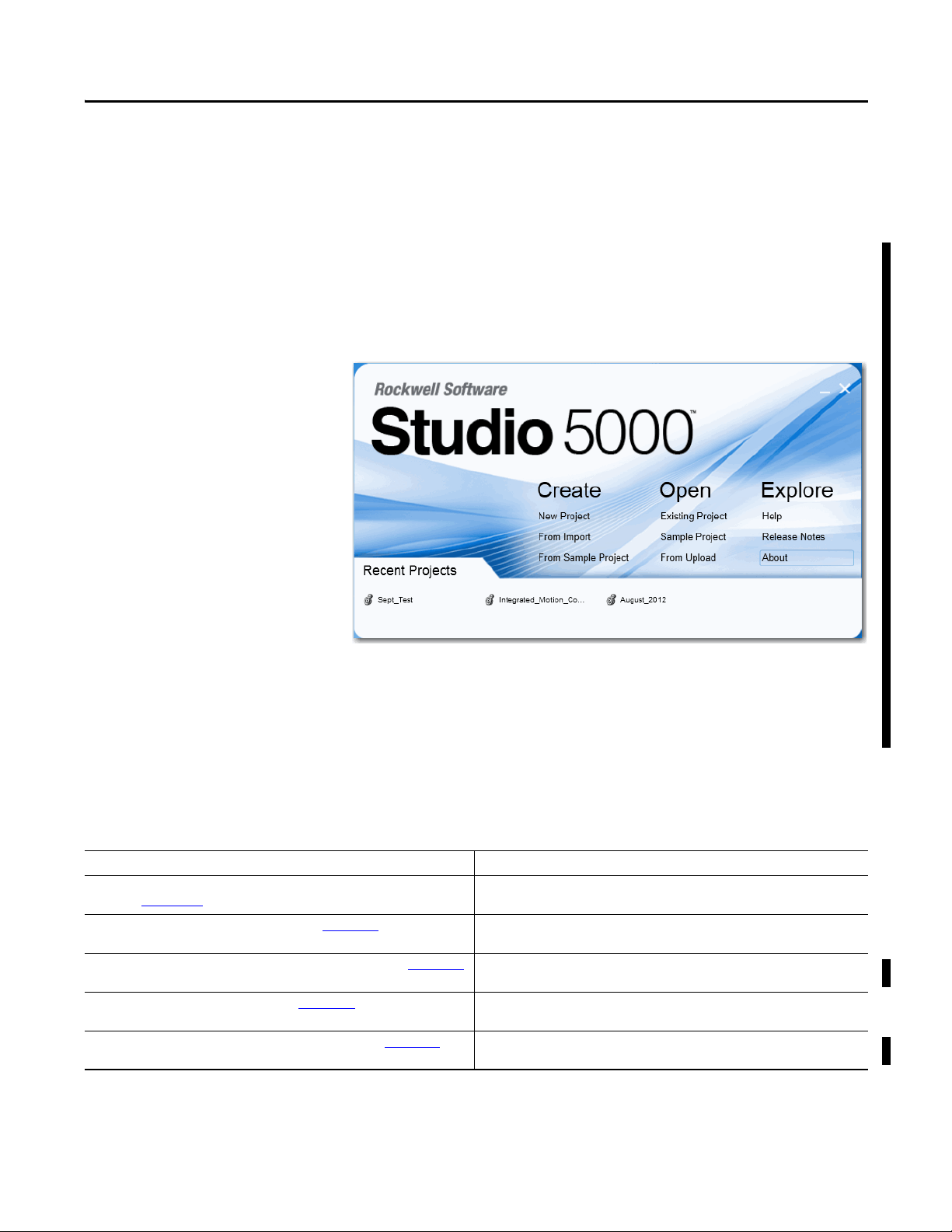
Studio 5000 Environment
The Studio 5000™ Engineering and Design Environment combines engineering
and design elements into a common environment. The first element in the Studio
5000 environment is the Logix Designer application. The Logix Designer
application is the rebranding of RSLogix™ 5000 software and will continue to be
the product to program Logix5000™ controllers for discrete, process, batch,
motion, safety, and drive-based solutions.
The Studio 5000 environment is the foundation for the future of Rockwell
Automation® engineering design tools and capabilities. This environment is the
one place for design engineers to develop all of the elements of their control
system.
Additional Resources
Refer to the following as needed for additional help when setting up and using
your modules. For specifications, refer to the relevant installation instructions.
Resource Description
CompactBlock Guard I/O EtherNet/IP Safety Modules Installation Instructions,
publication 1791ES-IN001
GuardLogix 5570 Controllers User Manual, publication 1756-UM022
GuardLogix 5570 Controller Systems Safety Reference Manual, publication 1756-RM099
GuardLogix Controllers User Manual, publication 1756-UM020 Provides information on how to install, configure, program, and use GuardLogix 5560 and
GuardLogix Controller Systems Safety Reference Manual, publication 1756-RM093
Rockwell Automation Publication 1791ES-UM001D-EN-P - May 2013 7
Provides detailed specifications and information related to installation of Guard I/O
modules.
Provides information on how to install, configure, program, and use GuardLogix 5570
controllers in Studio 5000 Logix Designer projects.
Provides information on safety application requirements for GuardLogix 5570 controllers
in Studio 5000 Logix Designer projects.
5570 controllers in RSLogix 5000 projects.
Provides information on safety application requirements for GuardLogix 5560 and 5570
controllers in RSLogix 5000 projects.
Page 8

Preface
Resource Description
GuardLogix Safety Application Instructions Safety Reference Manual, publication
1756-RM095
Ethernet Design Considerations Reference Manual, publication ENET-RM002 Describes the required media components and how to plan for and install these required
ODVA Media Planning and Installation Manual, publication 00148-BR00
the EtherNet/IP Library at ODVA.org
, available from
Provides reference information describing the GuardLogix Safety Application Instruction
Set.
components.
Describes the required media components and how to plan for and install these required
components.
You can view or download publications at
http://www.rockwellautomation.com/literature/
. To order paper copies of
technical documentation, contact your local Allen-Bradley distributor or
Rockwell Automation sales representative.
About the Specifications and Dimensions in This Manual
Product specifications and accessories can change at any time based on
improvements and other reasons. Consult with your Rockwell Automation
representative to confirm actual specifications of purchased product. Dimensions
and weights are nominal and are not for use for manufacturing purposes, even
when tolerances are shown.
Terminology
Term Definition
Connection Logical communication channel for communication between nodes. Connections are maintained and controlled between masters and slaves.
EDS Acronym for electronic data sheet, a template that RSNetWorx software uses to display the configuration parameters, I/O data profile, and connection-type
support for a given I/O module. These are simple tex t files used by RSNetWorx software for you to identify products and commission them on a network.
L- Output +24V DC common.
M Sinking output common channel, output switches to the common voltage.
MTBF Acronym for mean time between failure, the average time between failure occurrences.
ODVA Acronym for Open DeviceNet Vendor Association, a nonprofit association of vendors established for the promotion of CIP networks.
P Sourcing output channel, output switches to the plus voltage.
PFD Acronym for probability of failure on demand, the average probability of a system to fail to perform its design function on demand.
PFH Acronym for probability of failure per hour, the probability of a system to have a dangerous failure occur per hour.
Proof test Periodic test per formed to detect failures in a safety-related system so that, if necessary, the system can be restored to an as-new condition or as close as
practical to this condition.
S+ Output +24V DC.
SNN Acronym for safety network number, which uniquely identifies a network across all networks in the safety system. You are responsible for assigning a
unique number for each safety network or safety sub-net within a system.
Standard Devices or portions of devices that do not par ticipate in the safety function.
Refer to the table for the meaning of common terms.
8 Rockwell Automation Publication 1791ES-UM001D-EN-P - May 2013
Page 9

About the Modules
Top ic Pa ge
Before You Begin 9
Understand Suitability for Use 10
Follow Precautions for Use 10
Precautions to Mount, Wire, and Clean 11
I/O Module Overview 12
About Catalog Numbers 13
Programming Requirements 14
About CIP Safety in EtherNet/IP Safety Architectures 14
Identify Major Parts of the Module 14
Chapter 1
Before You Begin
This chapter includes important overview information and precautions for use of
the Guard I/O modules that implement the EtherNet/IP safety protocol. Also
included is an overview on how these I/O modules are used within a safety
system.
Always observe the following when using a module, noting that in this manual we
use safety administrator to mean a person qualified, authorized, and responsible
to secure safety in the design, installation, operation, maintenance, and disposal
of the machine.
• Thoroughly read and understand this manual before installing and
operating the module.
• Keep this manual in a safe place where personnel can refer to it when
necessary.
• Use the module properly according to the installation environment,
performance, and functions of the machine.
• Verify that a safety administrator conducts a risk assessment on the
machine and determines module suitability before installation.
Verify for CE LVD compliance, the external power supply that provides power to
the modules is safety extra-low voltage (SELV) rated. Some Rockwell
Automation Bulletin 1606 power supplies are SELV-compliant. Verify Bulletin
1606 Installation Instructions.
Rockwell Automation Publication 1791ES-UM001D-EN-P - May 2013 9
Page 10
Chapter 1 About the Modules
Verify that the Guard I/O firmware version is correct prior to commissioning the
safety system, noting that firmware information related to safety controllers is
available at:
http://www.rockwellautomation.com/products/certification/
Understand Suitability for Use
Follow Precautions for Use
Rockwell Automation is not responsible for conformity with any standards,
codes, or regulations that apply to the combination of the products in your
application or use of the product.
Take all necessary steps to determine the suitability of the product for the
systems, machine, and equipment with which it is used.
Know and observe all prohibitions of use applicable to this product.
Never use the products for an application involving serious risk to life or property
without making sure that the system as a whole was designed to address the risks
and that the Rockwell Automation product is properly rated and installed for the
intended use within the overall equipment or system.
ATT EN TI ON :
• Safety state of the inputs and outputs is defined as the off state.
• Safety state of the module and its data is defined as the off state.
• Use the Guard I/O module only in applications where the off state is the safety
state.
• Serious injury can occur due to breakdown of safety outputs. Do not connect
loads beyond the rated value to the safety outputs.
• Serious injury can occur due to loss of required safety functions. Wire the
module properly so that supplyy voltages or voltages for loads do not touch
the safety outputs accidentally or inadvertently.
10 Rockwell Automation Publication 1791ES-UM001D-EN-P - May 2013
Page 11

About the Modules Chapter 1
ATTENTION: Use a DC power supply satisfying the following
requirements to prevent electric shock:
• A DC power sup ply wi th dou ble or reinforced i nsulatio n, for examp le,
according to IED/EN 60950 or EN 50178 or a transformer according to
IEC/EN 61558
• A DC supply satisfies requirement for class 2 circuits or limited
voltage/current circuit stated in UL 508
• Use an external power supply that is safety extra-low voltage (SELV)
rated
• Follow these precautions for safe use.
• Wire conductors correctly and verify operation of the module before
placing the system into operation. Incorrect wiring can lead to loss of
safety function.
• Do not apply DC voltages exceeding the rated voltages to the
module.
• Apply properly specified voltages to the module inputs. Applying
inappropriate voltages causes the module to fail to perform its
specified function, which leads to loss of safety functions or damage
to the module.
• Never use test outputs as safety outputs. Test outputs are not safety
outputs.
• Note that after installation of the module, a safety administrator
must confirm the installation and conduct trial operation and
maintenance.
• Do not disassemble, repair, or modify the module. This can result in
loss of safety functions.
• Use only appropriate components or devices complying with
relevant safety standards corresponding to the required safety
category and safety integrity level.
- Conformity to requirements of the safety category and safety
integrity level must be determined for the entire system.
- We recommend you consult a certification body regarding
assessment of conformity to the required safety integrity level or
safety category.
• Note that you must confirm compliance with the applicable
standards for the entire system.
• Disconnect the module from the power supply before wiring.
Devices connected to the module can operate unexpectedly if wiring
is performed while power is supplied.
Precautions to Mount, Wire, and Clean
Observe these precautions to prevent operation failure, malfunctions, or
undesirable effects on product performance.
Follow these precautions when mounting modules.
• Use DIN rail that is 35 mm (1.38 in.) wide to mount the module into the
control panel.
• Mount modules to DIN rail securely.
• Leave at least 15 mm (0.6 in.) around the module to allow adequate
ventilation and room for wiring.
Rockwell Automation Publication 1791ES-UM001D-EN-P - May 2013 11
Page 12

Chapter 1 About the Modules
Follow these instructions when wiring modules.
• Do not place communication lines and I/O lines in the same wiring duct
or track as high voltage lines.
• Wire correctly after confirming the signal names of all terminals.
• Follow torquing specifications as indicated in the installation instructions.
When cleaning modules, do not use the following:
• Thinner
• Benzene
• Acetone
I/O Module Overview
The Guard I/O modules implement the CIP-safety protocol extensions over
EtherNet/IP networks and provide various features for a safety system.
Use the modules to construct a safety-control network system that meets the
requirements up to Safety Integrity Level 3 (SIL 3) as defined in IEC 61508,
Functional Safety of Electrical, Electronic, and Programmable Electronic
Safety-related Systems, and the requirements for Safety Category 4 of the
EN 954-1 standard, Safety of machinery - Safety related parts of control systems.
Remote I/O communication for safety I/O data are performed through safety
connections supporting CIP safety over an EtherNet/IP network, and data
processing is performed in the safety controller.
The status and fault diagnostics of the I/O modules are monitored by a safety
controller through a safety connection by using a new or existing EtherNet/IP
network.
12 Rockwell Automation Publication 1791ES-UM001D-EN-P - May 2013
Page 13

About the Modules Chapter 1
The following is a list of features common to Guard I/O modules:
• CIP-safety and EtherNet/IP protocol conformance
• Safety inputs
– Safety devices, such as emergency stop push buttons, gate switches, and
safety light curtains, can be connected.
– Dual-channel mode evaluates consistency between two input signals
(channels), which allows use of the module for Safety Category 3 and 4.
– The time of a logical discrepancy between two channels can be
monitored by using a discrepancy time setting.
– An external wiring short-circuit check is possible when inputs are wired
in combination with test outputs.
– Independently adjustable on and off delay is available per channel.
• Te st ou tp u ts
– Separate test outputs are provided for short circuit detection of a safety
input (or inputs).
– Power (24V) can be supplied to devices, such as safety sensors.
– Test outputs can be configured as standard outputs.
– All Guard I/O modules have numerous test outputs, of which some can
be used for broken wire detection of a muting lamp.
• Safety outputs
– Dual-channel mode evaluates consistency between two output signals
(channels).
– Safety outputs can be pulse tested to detect field wiring shorts to
24V DC and 0V DC.
• I/O status data - In addition to I/O data, the module includes status data
for monitoring I/O circuits.
• Removable I/O connectors - I/O connectors support mechanical keying.
About Catalog Numbers
Catalog Number Description Enclosure Type
1791ES-IB16 Safety input module Meets IP20 16 16 —
1791ES-IB8XOBV4 Safety I/O module with solid state outputs 8 8 4 bipolar pairs
(1) Broken wires can be detected on the muting outputs.
See the table for a listing of the types of Guard I/O modules.
Rating
Safety Inputs Test Outputs
Rockwell Automation Publication 1791ES-UM001D-EN-P - May 2013 13
(1)
Safety Outputs
Solid State
Page 14
Chapter 1 About the Modules
EtherNet/IP Network
ControlNet Network
DeviceNet Network
DeviceNet
Network
EtherNet
EtherNet
RSLogix Software
RSView Software
Control Net
Network
DeviceNet Network
DeviceNet
Network
Standard Communication
Safety Communication
Programming Requirements Use the minimum software versions listed here.
Cat. No. Studio 5000 Environment
1791ES-IB16 21 16
1791ES-IB8XOBV4 21 16
(1) This version or later.
Versio n
(1)
RSLogix 5000 Software Version
(EtherNet/IP Network)
(1)
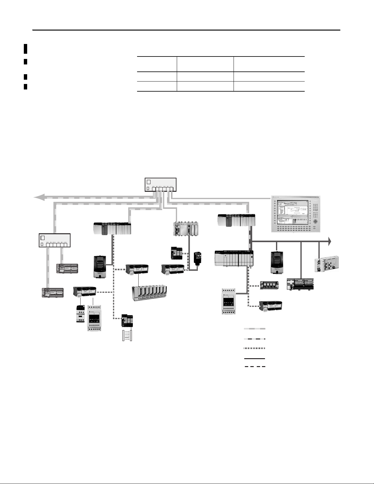
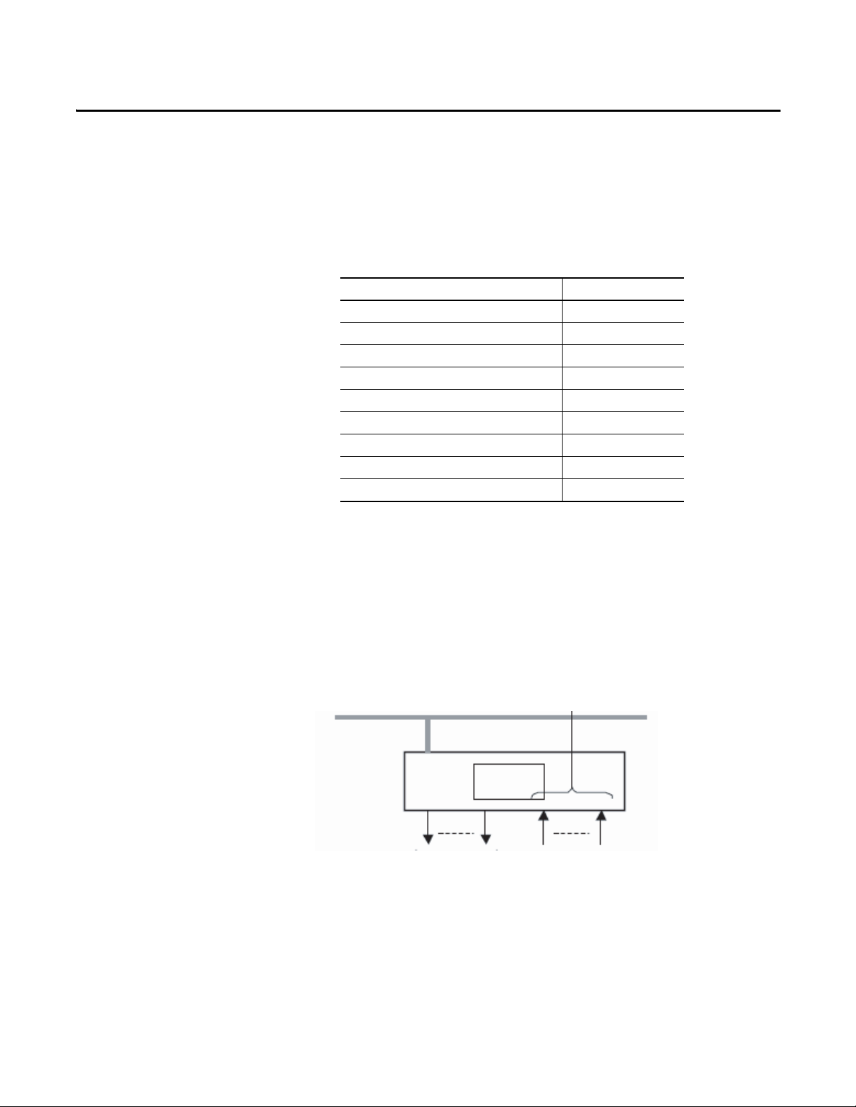
About CIP Safety in EtherNet/IP Safety Architectures
Use Guard I/O modules in EtherNet/IP safety architectures as shown in the
figure. The Guard I/O family is a set of I/O modules that when connected to an
EtherNet/IP safety network are suitable for applications up to SIL3, as defined in
the IEC 61508 standard, and Safety Category 4, as defined in the EN 954-1
standard.
Figure 1 - Safety Interlocking and Control via CIP Safety
Safety controllers control the safety outputs. Safety or standard controllers can
control the standard outputs.
Identify Major Parts of the Module
14 Rockwell Automation Publication 1791ES-UM001D-EN-P - May 2013
See the figure for module identification. For pin-out information, refer to the
relevant installation instructions.
Page 15
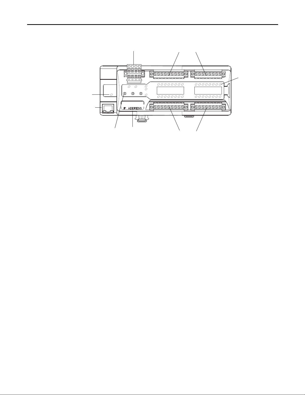
Figure 2 - Major Module Parts
I/O Connectors
I/O Connectors
Power Connector
LED Status
Indicators
IP Address
Switch
EtherNet IP Address
Label
EtherNet
Connecto r
Network
Activity
Indicator
About the Modules Chapter 1
Rockwell Automation Publication 1791ES-UM001D-EN-P - May 2013 15
Page 16

Chapter 1 About the Modules
Notes:
16 Rockwell Automation Publication 1791ES-UM001D-EN-P - May 2013
Page 17
Chapter 2
Output Off
Input
Inputs to Network Off
EtherNet/IP Network
Safety
Status
44076
Understand the Operation of Safety Functions
Top ic Pa ge
Self-diagnostic Functions 18
Configuration Lock 18
I/O Status Data 18
Safety Inputs 18
Safety Outputs 27
Controlling D evices 28
Safety Precautions 29
Legislation and Standards 29
EC Directives 31
Read this chapter for information related to the safety functions of the modules.
Also included is a brief overview on international standards and directives that
you must be familiar with.
The following status is the safety state of the Guard I/O modules:
• Safety outputs: off
• Safety input data to network: off
Figure 3 - Safety Status
The module is designed for use in applications where the safety state is the off
state.
Rockwell Automation Publication 1791ES-UM001D-EN-P - May 2013 17
Page 18

Chapter 2 Understand the Operation of Safety Functions
Self-diagnostic Functions
Configuration Lock
I/O Status Data
Self-diagnostics are performed when the power is turned on and periodically
during operation. If a fatal internal module error occurs, the red module status
(MS) indicator is illuminated, and the safety outputs and input data and status to
the network turn off.
After configuration data has been downloaded and verified, the configuration
data within the module can be protected.
For GuardLogix systems, the LED indicator is not used. Reference information
about safety signatures in the GuardLogix Controller Systems Safety Reference
Manual, publication 1756-RM093
In addition to I/O data, the module provides status data for monitoring the I/O
circuits. The status data includes the following data, which can be read by the
controllers. Note that 1 = ON/Normal and 0 = OFF/Fault/Alarm.
• Individual Point Input Status
• Combined Input Status
• Individual Point Output Status
• Combined Output Status
• Individual Test Output Status
• Individual Output Readback (actual ON/OFF state of the outputs)
.
Safety Inputs
Status data indicate whether each safety input, safety output, or test output is
normal (normal status: ON, faulted status: OFF). For fatal errors,
communication connections can be broken, so the status data cannot be read.
Combined status is provided by an AND of the status of all safety inputs or all
safety outputs. When all inputs or outputs are normal the respective combined
status is ON. When one or more of them has an error the respective combined
status is OFF. This is known as the combined safety input status or combined
safety output status.
Read this section for information about safety inputs and their associated test
outputs. A safety input can be used with test outputs. Safety inputs are used to
monitor safety input devices.
18 Rockwell Automation Publication 1791ES-UM001D-EN-P - May 2013
Page 19
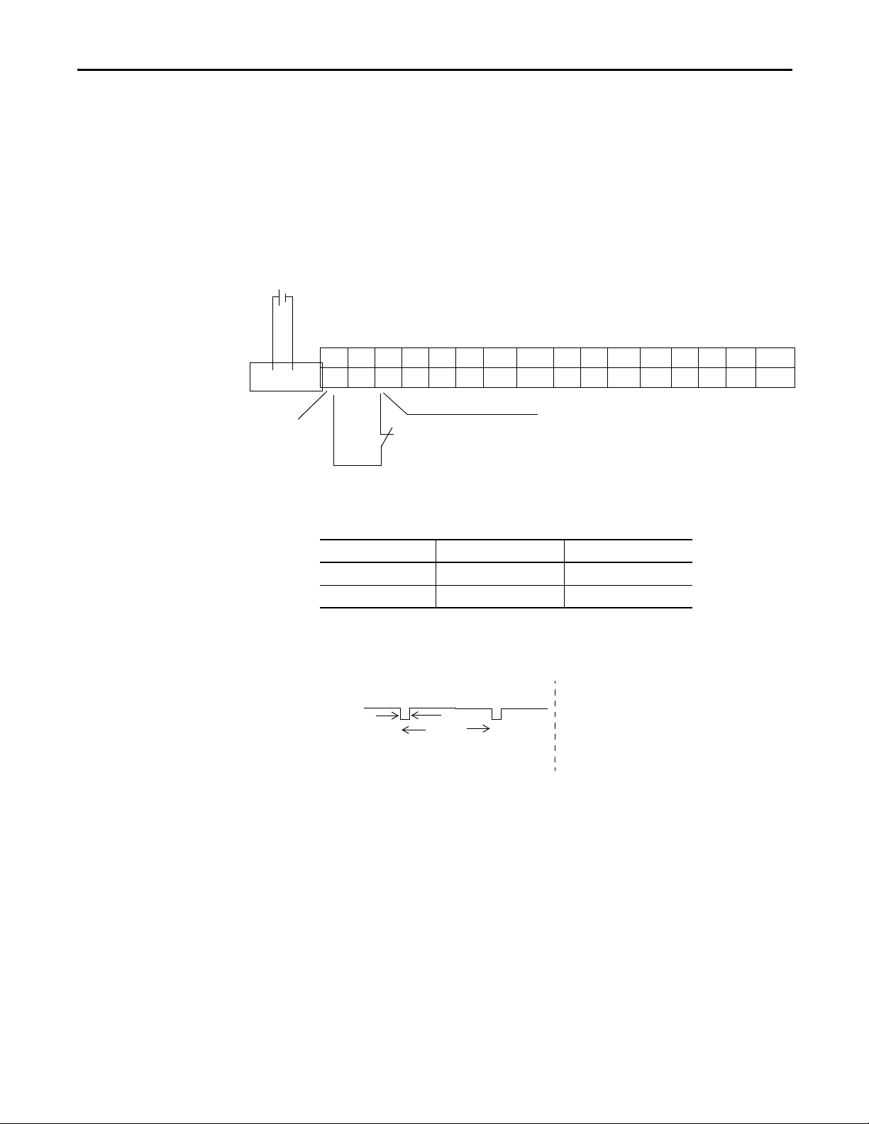
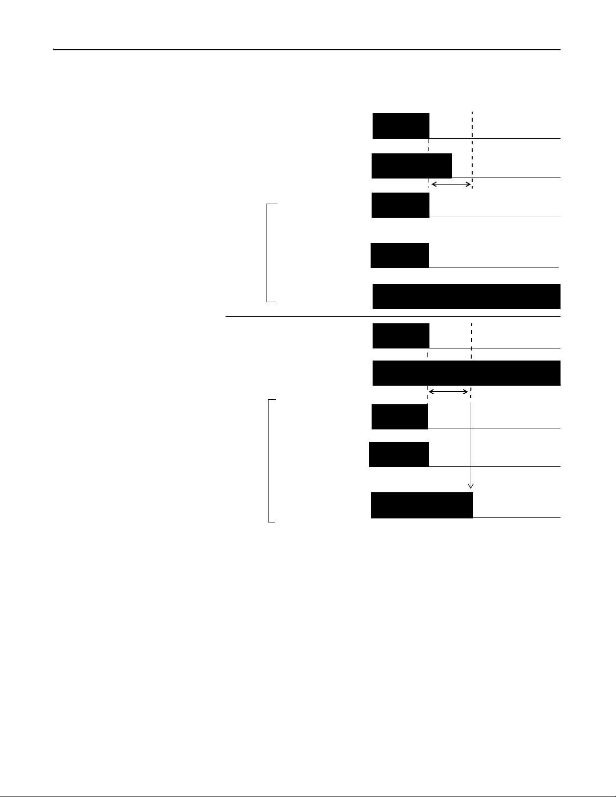
Using a Test Output with a Safety Input
I8 I9 T8 T9 I10 I11 T10 T11M I12 I13 T12 T13 I14 I15 T14 T15M
I0 I1 T0 T1 I2 I3 T2 T3M I4 I5 T4 T5 I6 I7 T6 T7M
IN+ IN-
24V DC
24V DC Output with Test Pulse
External Contact
Safety Input
44295
OUT
On
Off
Typ ic al
500 μs
Typ ic al
150 ms
A test output can be used in combination with a safety input for short circuit
detection. Configure the test output as a pulse test source and associate it to a
specific safety input.
The test output can also be used as a power supply to source 24V DC for an
external input circuit.
Figure 4 - Example Use of a 1791ES-IB16 Module
Understand the Operation of Safety Functions Chapter 2
Table 1 - Typical Pulse Width and Period
Attribute 1791ES-IB8XOBV4 1791ES-IB16
Pulse width 500 μs 500 μs
Period 150 ms 150 ms
Figure 5 - Test Pulse in a Cycle
Rockwell Automation Publication 1791ES-UM001D-EN-P - May 2013 19
Page 20
Chapter 2 Understand the Operation of Safety Functions
T0
IN0
T1
IN1
IN+
IN-
External
Short-circuit Between Input Signal Lines and Power
Supply (Positive Side)
External Contact
Short-circuit Between Input Signal Lines
44079
When the external input contact is closed, a test pulse is output from the test
output terminal to diagnose the field wiring and input circuitry. By using this
function, short-circuits between input signal lines and the power supply (positive
side), and short-circuits between input signal lines can be detected.
Figure 6 - Short-circuit Between Input Signal Lines
24V
24V
0V
20 Rockwell Automation Publication 1791ES-UM001D-EN-P - May 2013
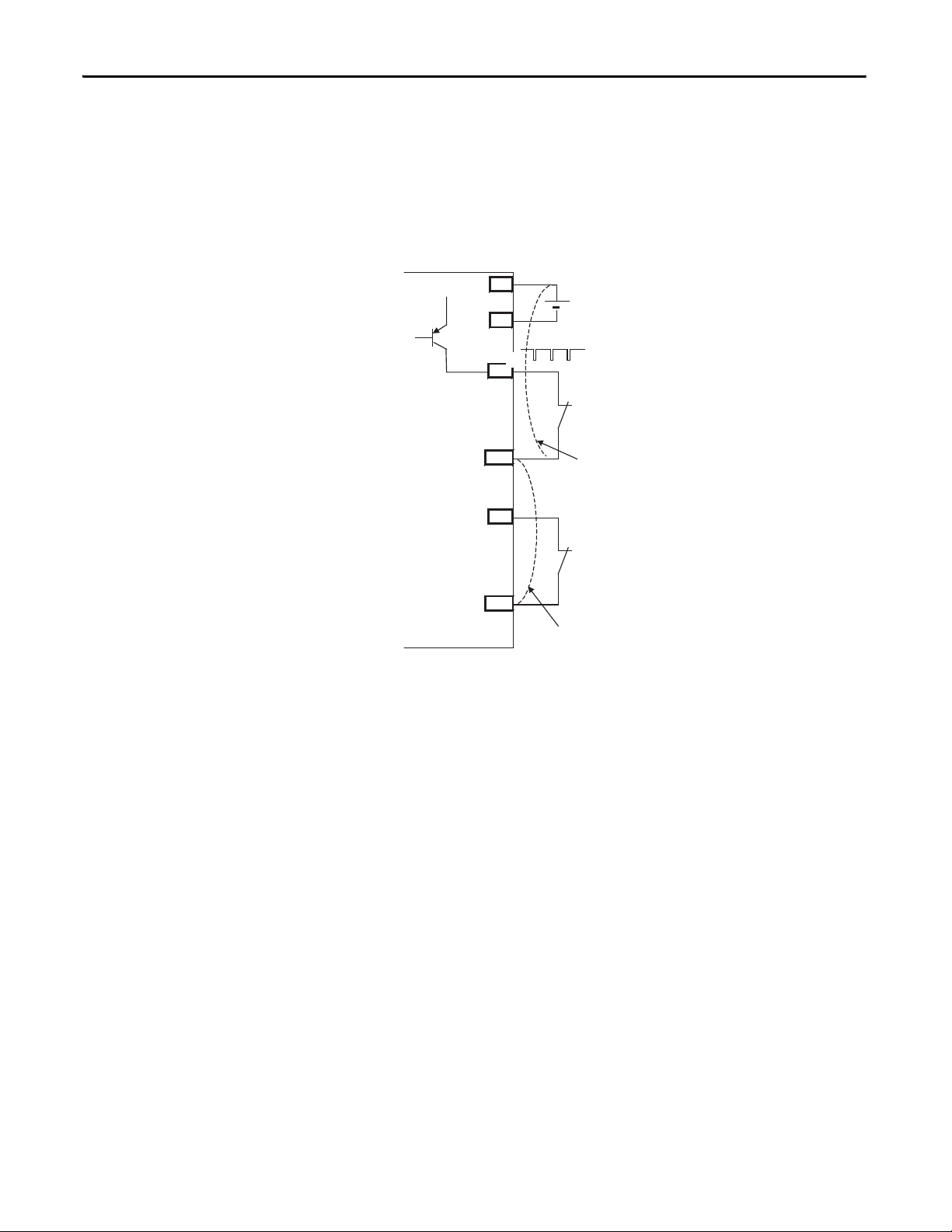
Page 21

Understand the Operation of Safety Functions Chapter 2
24V
0V
T0
Input Terminal 0
External Device
Faul t De tected
Remote
I/O
Data
ON
OFF
ON
OFF
ON
OFF
ON
OFF
24V
0V
ON
OFF
T0
Safety Input
Status 0
Fault Detection
Remote
I/O
Data
ON
OFF
ON
OFF
ON
OFF
Safety Input
Status 0
Safety Input 0
Safety Input 0
Input Terminal 0
Normal Operation
External Device
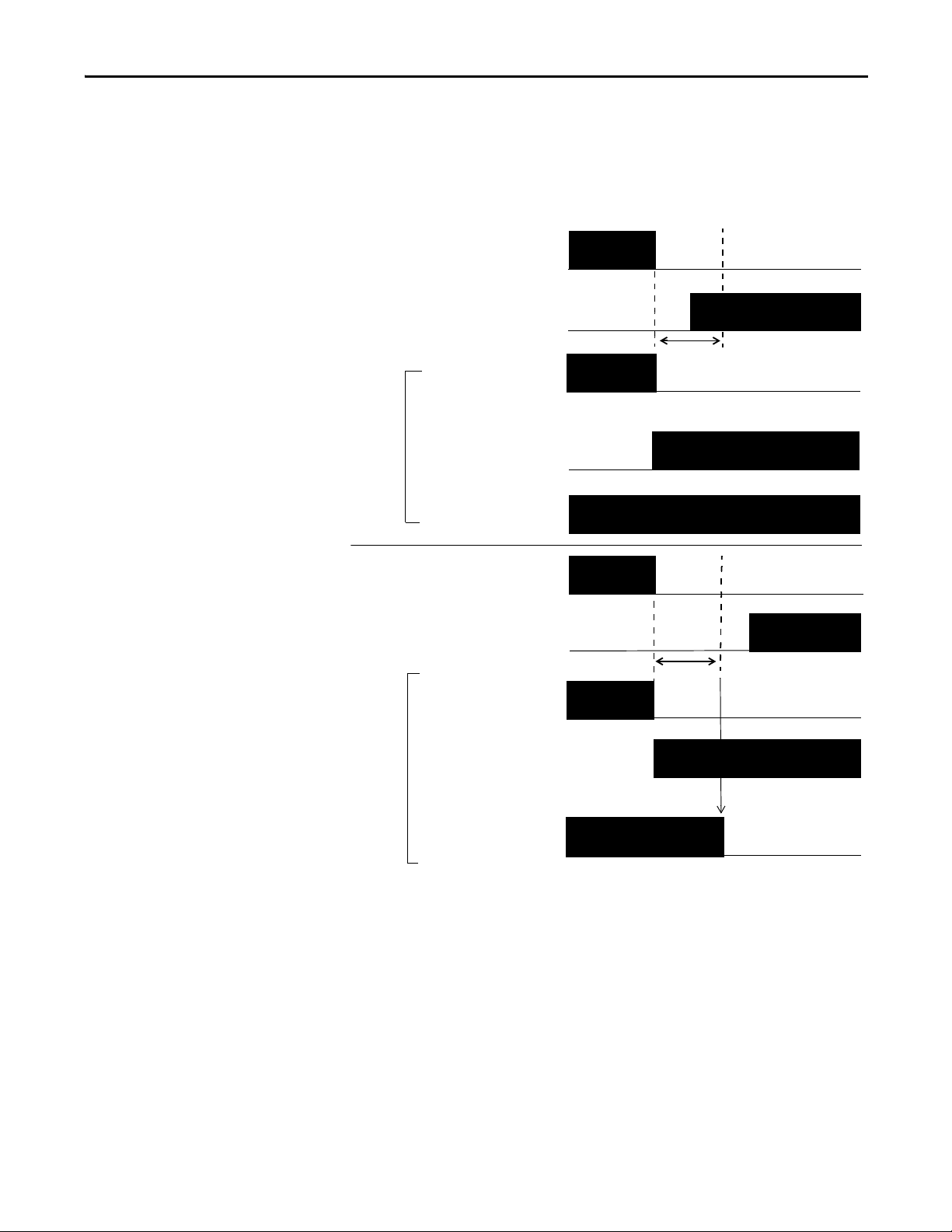
If an error is detected, safety input data and safety input status turns off.
Figure 7 - Normal Operation and Fault Detection (not to scale)
Rockwell Automation Publication 1791ES-UM001D-EN-P - May 2013 21
Page 22

Chapter 2 Understand the Operation of Safety Functions
IMPORTANT
IMPORTANT
Set Dual-channel Mode and Discrepancy Time
To support redundant channel safety devices, the consistency between signals on
two channels can be evaluated. Either equivalent or complementary can be
selected. This function monitors the time during which there is a discrepancy
between the two channels.
If the length of the discrepancy exceeds the configured discrepancy time
(0…65,530 ms in increments of 10 ms), the safety input data and the
individual-safety input status turns off for both channels.
The dual-channel function is used with two consecutive inputs that are
paired together, starting at an even input number, such as inputs 0 and 1, 2
and 3, and so on.
Do not set the discrepancy time longer than necessary. The purpose of the
discrepancy time is to allow for normal differences between contact
switching when demands are placed on safety inputs. For this testing to
operate correctly, only a single demand on the safety input is expected
during the discrepancy time. If the discrepancy time is set too high, and
multiple demands occur during this time, then both safety input channels
will fault.
22 Rockwell Automation Publication 1791ES-UM001D-EN-P - May 2013
Page 23

The following table shows the relation between input terminal states and
controller input data and status.
Table 2 - Terminal Input Status and Controller I/O Data
Understand the Operation of Safety Functions Chapter 2
Dual-channel Mode Input Terminal Controller Input Data and Status Dual- channel
IN0 IN1 Safety
Dual-channels, Equivalent OFF OFF OFF OFF ON ON OFF Normal
OFF ON OFF OFF OFF OFF OFF Fault
ON OFF OFF OFF OFF OFF OFF Fault
ON ON ON ON ON ON ON Normal
Dual-channels,
Complementary
OFF OFF OFF ON OFF OFF OFF Fault
OFF ON OFF ON ON ON OFF Normal
ON OFF ON OFF ON ON ON Normal
ON ON OFF ON OFF OFF OFF Fault
Input 0 Data
Safety
Input 1 Data
Safety
Input 0 Status
Safety
Input 1 Status
Resultant
Data
Dual-channel
Resultant
Status
Dual-channels, Equivalent
In Equivalent mode, both inputs of a pair must typically be in the same
(equivalent) state. When a transition occurs in one channel of the pair, prior to
the transition of the second channel of the pair, a discrepancy occurs. If the
second channel transitions to the appropriate state prior to the discrepancy time
elapsing, the inputs are considered equivalent. If the second transition does not
occur before the discrepancy time elapses, the channels will fault. In the fault state
the input and status for both channels are set low (off). When configured as an
equivalent dual pair, the data bits for both channels will always be sent to the
controller as equivalent, both high or both low.
Rockwell Automation Publication 1791ES-UM001D-EN-P - May 2013 23
Page 24
Chapter 2 Understand the Operation of Safety Functions
ON
OFF
IN0
Safety Input 0
IN1
Fault Detec ted
Discrepancy Time
Remote
I/O
Data
ON
OFF
ON
OFF
ON
OFF
ON
OFF
ON
OFF
ON
OFF
IN0
Safety Input
Status 0, 1
IN1
Fault Detection
Remote
I/O
Data
ON
OFF
ON
OFF
ON
OFF
Discrepancy Time
Safety Input
Status 0, 1
Safety Input 1
Safety Input 1
Safety Input 0
Normal Operation
Figure 8 - Equivalent, Normal Operation and Fault Detection (not to scale)
Dual-channels, Complementary
In Complementary mode, the inputs of a pair must typically be in the opposite
(complementary) state. When a transition occurs in one channel of the pair prior
to the transition of the second channel of the pair, a discrepancy occurs. If the
second channel transitions to the appropriate state prior to the discrepancy time
elapsing, the inputs are considered complementary.
If the second transition does not occur before the discrepancy time elapses, the
channels will fault. The fault state of complementary inputs is the even numbered
input turned off and the odd numbered input turned on. Note that if faulted,
24 Rockwell Automation Publication 1791ES-UM001D-EN-P - May 2013
Page 25
Understand the Operation of Safety Functions Chapter 2
ON
OFF
IN0
Safety Input 0
IN1
Faul t De tected
Discrepancy Time
Remote
I/O
Data
ON
OFF
ON
OFF
ON
OFF
ON
OFF
ON
OFF
ON
OFF
IN0
Safety Input
Status 0, 1
IN1
Fault Detection
Remote
I/O
Data
ON
OFF
ON
OFF
ON
OFF
Discrepancy Time
Safety Input
Status 0, 1
Safety Input 1
Safety Input 1
Safety Input 0
Normal
Operation
both channel status bits are set low. When configured as a complementary dual
channel pair, the data bits for both channels will always be sent to the controller
in complementary, or opposite states.
Figure 9 - Complementary, Normal Operation and Fault Detection (not to scale)
Rockwell Automation Publication 1791ES-UM001D-EN-P - May 2013 25
Page 26

Chapter 2 Understand the Operation of Safety Functions
44094
On-delay
ON
OFF
ON
OFF
Input Signal
Remote I/O
Data Safety
Input
44094
44095
Remote I/O Data
Safety Input
Off-delay
Input Signal
ON
OFF
ON
OFF
Safety Input Fault Recovery
If an error is detected, the safety input data remains in the off state. The
procedure for activating the safety input data again is as follows.
1. Remove the cause of the error.
2. Place the safety input (or safety inputs) into the safety state.
The safety input status turns on (fault cleared) after the input-error latch
time has elapsed. The I/O indicator (red) turns off. The input data can
now be controlled.
Input Delays
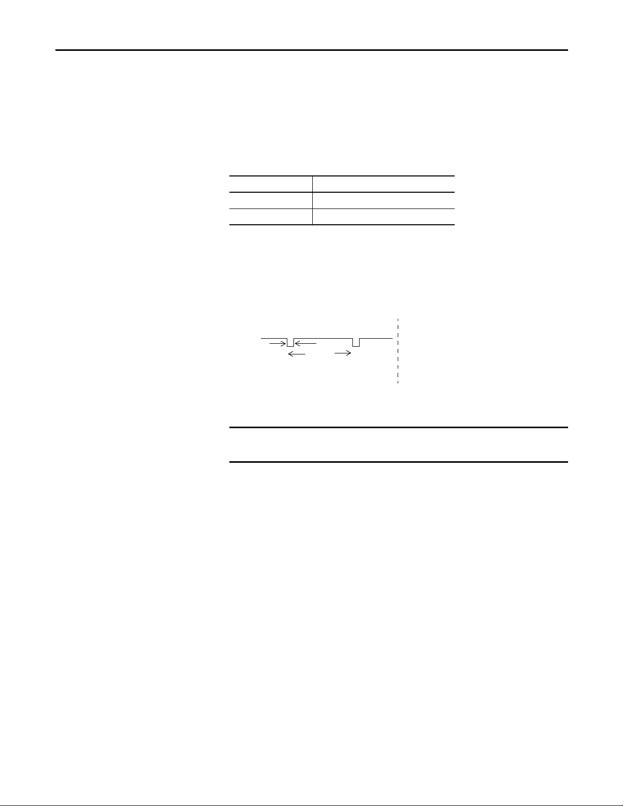
On-delay - An input signal is treated as logic 0 during the on-delay time (0…126
ms, in increments of 6 ms) after the input contact’s rising edge. The input only
turns on if the input contact remains on after the on-delay time has elapsed. This
helps prevent rapid changes of the input data due to contact bounce.
Figure 10 - On-delay
Input
ON
OFF
ON
OFF
ON-delay
Input Signal
Remote I/O
Data Safety
Off-delay - An input signal is treated as logic 1 during the off-delay time (0…126
ms, in increments of 6 ms) after the input contact’s falling edge. The input only
turns off if the input contact remains off after the off delay time has elapsed. This
helps prevent rapid changes of the input data due to contact bounce.
Figure 11 - Off-delay
Input Signal
Remote I/O Data
Safety Input
OFF
ON
OFF
OFF-delay
26 Rockwell Automation Publication 1791ES-UM001D-EN-P - May 2013
Page 27
Understand the Operation of Safety Functions Chapter 2
IMPORTANT
44096
OUT
On
Off
Typ ic al
700 μs
Typ ic al
600 ms
Safety Outputs
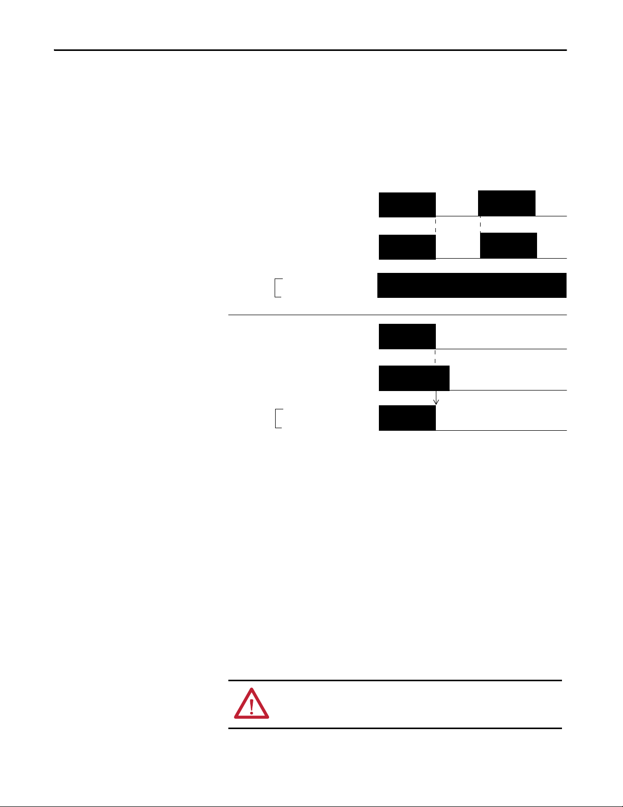
Read this section for information about safety outputs.
Safety Output with Test Pulse
When the safety output is on, the safety output can be test pulsed, as shown in
the figure and table.
Attribute 1791ES-IB8XOBV4
Pulse width 700 μs
Period 600 ms
By using this function, short-circuits between output signal lines and the power
supply (positive side) and short-circuits between output signal lines can be
detected. If an error is detected, the safety output data and individual-safety
output status turns off.
Figure 12 - Test Pulse in a Cycle
To prevent the test pulse from causing the connected device to
malfunction, pay careful attention to the input response time of the device.
Rockwell Automation Publication 1791ES-UM001D-EN-P - May 2013 27
Page 28
Chapter 2 Understand the Operation of Safety Functions
ON
OFF
OUT0
Safety Output
Status 0, 1
OUT0
OUT1
OUT1
Safety Output
Status 0, 1
Fault Detection
Error
Detected
Remote
I/O
Data
Remote
I/O
Data
ON
OFF
ON
OFF
ON
OFF
ON
OFF
ON
OFF
Normal Oper ation
Dual-channel Setting
When the data of both channels is in the on state, and neither channel has a fault,
the outputs are turned on. The status is normal. If a fault is detected on one
channel, the safety output data and individual safety output status turn off for
both channels.
Figure 13 - Dual-channel Setting (not to scale)
Safety Output Fault Recovery
If a fault is detected, the safety outputs are switched off and remain in the off
state. The procedure for activating the safety output data again is as follows.
Controlling Devices
28 Rockwell Automation Publication 1791ES-UM001D-EN-P - May 2013
1. Remove the cause of the error.
2. Place the safety output (or safety outputs) into the safety state.
The safety output status turns on (fault cleared) when the output-error
latch time has elapsed. The I/O indicator (red) turns off. The output data
can now be controlled.
See the table for information about controlling devices.
ATTENTION: Use appropriate devices as indicated in the Controlling
Device Requirements table. Serious injury can occur due to loss of safety
functions.
Page 29

Understand the Operation of Safety Functions Chapter 2
Table 3 - Controlling Device Requirements
Device Requirement Allen-Bradley Bulletin Safety Components
Emergency stop switches Use approved devices with direct opening mechanisms complying with IEC/EN
Door interlocking switches,
limit switches
Safety sensors Use approved devices complying with the relevant product standards,
Relays with forcibly- guided
contacts,
contactors
Other devices Evaluate whether devices used are appropriate to satisfy the requirements of
60947-5-1.
Use approved devices with direct opening mechanisms complying with IEC/EN
60947-5-1 and capable of switching microloads of 24V DC 5 mA.
regulations, and rules in the country where used.
Use approved devices with forcibly-guided contacts complying with EN 50205. For
feedback purposes, use devices with contacts capable of switching micro loads of
24V DC 5 mA.
safety category levels.
Bulletin 800F, 800T
Bulletin 440K, 440G, 440H for interlock switch
Bulletin 440P, 802T for limit switch
Any Guardmaster product
Bulletin 700S, 100S
—
Safety Precautions
ATTENTION: As serious injury can occur due to loss of required safety function,
follow these safety precautions:
• Do not use test outputs of the modules as safety outputs.
• Do not use EtherNet/IP standard I/O data or explicit message data as
safety data.
• Do not use LED indicators on the I/O modules for safety operations.
• Do not connect loads beyond the rated value to the safety outputs.
• Wire the Guard I/O modules properly so that 24V DC line does not touch
the safety outputs accidentally or unintentionally.
• Clear previous configuration data before connecting devices to the
network.
• Set suitable IP addresses before connecting devices to the network.
• Perform testing to confirm that all of the device configuration data and
operation is correct before starting system operation.
• When replacing a device, configure the replacement device suitably and
confirm that it operates correctly.
• When installing or replacing modules, clear any previous configuration
before connecting input or output power to the device.
Legislation and Standards
Read this section to familiarize yourself with related legislation and standards
information. Relevant international standards include the following:
• IEC 61508 (SIL 1-3)
• IEC 61131-2
• IEC 60204-1
• IEC 61000-6-2
• IEC 61000-6-4
The modules received the following certification from ODVA, when product is
marked.
Rockwell Automation Publication 1791ES-UM001D-EN-P - May 2013 29
Page 30

Chapter 2 Understand the Operation of Safety Functions
• EtherNet/IP Conformance
• EtherNet/IP Safety Conformance
Europe
In Europe, the modules are subject to the European Union (EU) Machinery
Directive Annex IV, B, Safety Components, items 1 and 2. The type approval of
TUV-Rheinland addresses compliance to applicable requirements of the
following directives and standards:
• EU legislation
– Machinery Directive 98/37/EC
– Low-voltage Directive 73/23/EEC
– EMC Directive 89/336/EEC
• European standards
– EN 61508 (SIL1-3)
– EN 954-1 (Category 4, 3, 2, 1, B)
– EN 61131-2
– EN 418
– EN 60204-1
– IEC 61000-6-2
– IEC 61000-6-4
North America
In North America, the TUV-Rheinland type approval includes Guard I/O
compliance to the relevant standards and related information including the
following:
• U.S. standards - ANSI RIA15.06, ANSI B11.19, NFPA 79
• The modules are UL-certified functionally safe and carry the NRGF label,
when product is marked.
• The modules received UL Listing to standards of U.S. and Canada
including the following, when product is marked.
Japan
In Japan, type test requirements are provided in Article 44 of the Industrial Safety
and Health Law. These requirements apply to complete systems and cannot be
applied to a module by itself. Accordingly, to use the module in Japan as a safety
device for press machine or shearing tool pursuant to Article 42 of the abovementioned law, it is necessary to apply for testing of the entire system.
30 Rockwell Automation Publication 1791ES-UM001D-EN-P - May 2013
Page 31

Understand the Operation of Safety Functions Chapter 2
EC Directives
These products conform to the EMC Directive and Low-voltage Directive. For
additional information, refer to the relevant installation instructions.
EMC Directive
Rockwell Automation devices that comply with EC directives also conform to
the related EMC standards so that they can more easily be built into other devices
or the overall machine. The actual products have been checked for conformity to
EMC standards. Whether they conform to the standards in the system used by
the customer, however, must be confirmed by the customer.
EMC-related performance of Rockwell Automation devices that comply with
EC directives vary depending on the configuration, wiring, and other conditions
of the equipment or control panel in which the Rockwell Automation devices are
installed. The customer must, therefore, perform the final check to confirm that
devices and the overall machine conform to EMC standards.
Compliance with EC Directives
EtherNet/IP products that comply with EC directives must be installed as
follows:
• All Type IP20 EtherNet/IP units must be installed within control panels.
• Use reinforced insulation or double insulation for the DC power supplies
used for the communication power supply, internal- circuit power supply,
and the I/O power supplies.
• EtherNet/IP products that comply with EC directives also conform to the
Common Emission Standard (EN 50081-2). Radiated emission
characteristics (10-m regulations) can vary depending on the configuration
of the control panel used, other devices connected to the control panel,
wiring, and other conditions. You must confirm that the overall machine
or equipment complies with EC directives.
Rockwell Automation Publication 1791ES-UM001D-EN-P - May 2013 31
Page 32

Chapter 2 Understand the Operation of Safety Functions
Notes:
32 Rockwell Automation Publication 1791ES-UM001D-EN-P - May 2013
Page 33
Install and Connect Your Modules
Top ic Pa ge
Install the Module 34
Connect the Ethernet Cable 35
Set Network (IP) Address 35
Connect I/O Power and I/O Cables 36
ATT EN TI ON : You can configure Test Outputs to be used as standard outputs.
You can connect actuators to Test Output points that are expecting a Standard
configuration.
Test Output points configured as Pulse Test or Power Supply become active
whenever you apply input power to the module. These configured functions are
independent of the I/O connections to the module.
Chapter 3
ATT EN TI ON : If a module with Test Outputs configured as Pulse Test or Power
Supply is incorrectly installed in an application where actuators are connected
to these Test Output points, the actuators are activated when input power is
applied.
To prevent this possibility, follow these procedures.
• When installing a module, be sure that the module is correctly configured for
the application or in the out-of-box condition before applying input power.
• When replacing a module, be sure that the module is correctly configured for
the application or in the out-of-box condition before applying input power.
• Reset modules to their out-of-box condition when removing them from an
application.
• Be sure that all modules in replacement stock are in their out-of-box condition.
Rockwell Automation Publication 1791ES-UM001D-EN-P - May 2013 33
Page 34

Chapter 3 Install and Connect Your Modules
IMPORTANT
Install the Module
Follow these instructions when installing a module.
• Use the module in an environment that is within the general
specifications.
• Use the module in an enclosure rated IP54 (IEC60529) or higher.
• Use DIN rail that is 35 mm (1.38 in.) wide to mount the module in
the control panel.
• Always use an end plate on each end of the module to secure it.
• Place other heat sources an appropriate distance away from the
module to maintain ambient temperatures around the module
below specified maximums.
• A 1791ES module can be installed either horizontally or vertically.
34 Rockwell Automation Publication 1791ES-UM001D-EN-P - May 2013
Page 35

Figure 14 - Required Spacing
Wiring D uct
15 mm (0.6 in.) Min
35 mm (1.38 in.) DIN Rail
Use horizontal or
vertical mounting.
End Plate
Wiring Duc t
15 mm (0.6 in.) Min
44407
End Plate
Install and Connect Your Modules Chapter 3
Use DIN rail that is 35 mm (1.38 in.) wide to install the module in the control
panel. See the figure that shows required spacing.
Connect the Ethernet Cable
See the Ethernet Design Considerations Reference Manual, publication
ENET-RM002
, for information about Ethernet cable.
Set Network (IP) Address
The module ships with the rotary switches set to 999 and DHCP enabled.
Rockwell Automation Publication 1791ES-UM001D-EN-P - May 2013 35
Page 36

Chapter 3 Install and Connect Your Modules
4
2
6
8
0
X100
X1
X10
4
2
6
8
0
4
2
6
8
0
This example shows the switches set at 163
with a network address being 192.168.1.163.
IMPORTANT
To set the network address, you can:
• adjust the switches on the front of the module.
• use a Dynamic Host Configuration Protocol (DHCP) server, such as
Rockwell Automation BootP/DHCP Server Utility.
• retrieve the IP address from nonvolatile memory.
The module reads the switches first to determine if the switches are set to a valid
number. You set the network address by adjusting the three switches on the front
of the module. Use a small-blade screwdriver to rotate the switches. Line up the
small notch on the switch with the number setting you wish to use. Valid settings
range from 001…254.
When the switches are set to a valid number, the module’s IP address is
192.168.1.xxx (where xxx represents the number set on the switches). The
module’s subnet mask is 255.255.255.0 and the gateway address is set to 0.0.0.0.
When the module is reading the network address set on the switches, the module
does not have a host name assigned to it or use any Domain Name System.
If the switches are set to an invalid number (such as 000 or a value greater than
254), the module checks to see if DHCP is enabled. If DHCP is enabled, the
module asks for an address from a DHCP server. The DHCP server also assigns
other transport control protocol (TCP) parameters.
Connect I/O Power and I/O Cables
If DHCP is not enabled, the module uses the IP address (along with other TCP
configurable parameters) stored in nonvolatile memory.
Figure 15 - Example Network Address
See installation instructions for specifications on wire type and size.
• Note that I/O connectors are detachable.
• Tighten the screws on the I/O connector to the specified torque settings
as shown in the installation instructions.
• Because the I/O connector has a structure that helps prevent incorrect
wiring, make connections at the specified locations corresponding to
the terminal numbers.
36 Rockwell Automation Publication 1791ES-UM001D-EN-P - May 2013
Page 37

Wiring Examples
I0 I1 T0 T1
44275
I0 I1 T0 T1
44276
24V DC
Top ic Pa ge
Examples of Wiring 39
Read this chapter for information about wiring and safety categories. See the
tables that show input device connection methods and their safety categories.
Table 4 - Input Device Connection Methods and Safety Categories
Connected Device Test Pulse from
Tes t Ou tpu t
Reset Switch No Connect the switch
Connection Schematic Diagram Safety
between I0 and T0. T0
must be configured as
24V power supply.
Chapter 4
Category
N/A
Connect the switch
between 24V DC and I0
Rockwell Automation Publication 1791ES-UM001D-EN-P - May 2013 37
N/A
Page 38

Chapter 4 Wiring Example s
I0 I1 T0 T1
44277
I0 I1 T0 T1
44278
I0 I1 T0 T1
24V DC
44279
OSSD2
OSSD1
44280
Table 4 - Input Device Connection Methods and Safety Categories (continued)
Connected Device Test Pulse from
Tes t Ou tpu t
Emergency stop switch
Yes Connect the switches
Door monitor
Connection Schematic Diagram Safety
between I0 and T0, and
I1 and T1
Category
4
No Connect the switches
between T0 and I0 and
I1, noting that T0 is
configured for 24V
power supply.
Connect the switches
between 24V DC and I0
and I1.
Light Curtain Yes Connect the OSSD1 and
OSSD2 to I0 and I1,
respec tively. Connect
the 24V power supply
commons.
3
3 or 4 based on
light curtain
being used
In - I0I1T0T1
38 Rockwell Automation Publication 1791ES-UM001D-EN-P - May 2013
24V
DC
COM
OSSD1
OSSD2
Page 39

Wiring E xample s Chapter 4
In + In -
FE I0 I1 T0 T1 I2 I3 T2 T3M
S2
PS1
S1
44281
PS1: User 24V DC power supply
S1: Emergency Stop Switch
(Positive Opening Mechanism)
Examples of Wiring
Read this section for examples of wiring by application. See catalog number
details for appropriate module.
Figure 16 - Emergency Stop Switch Dual-channel Inputs with Manual Reset
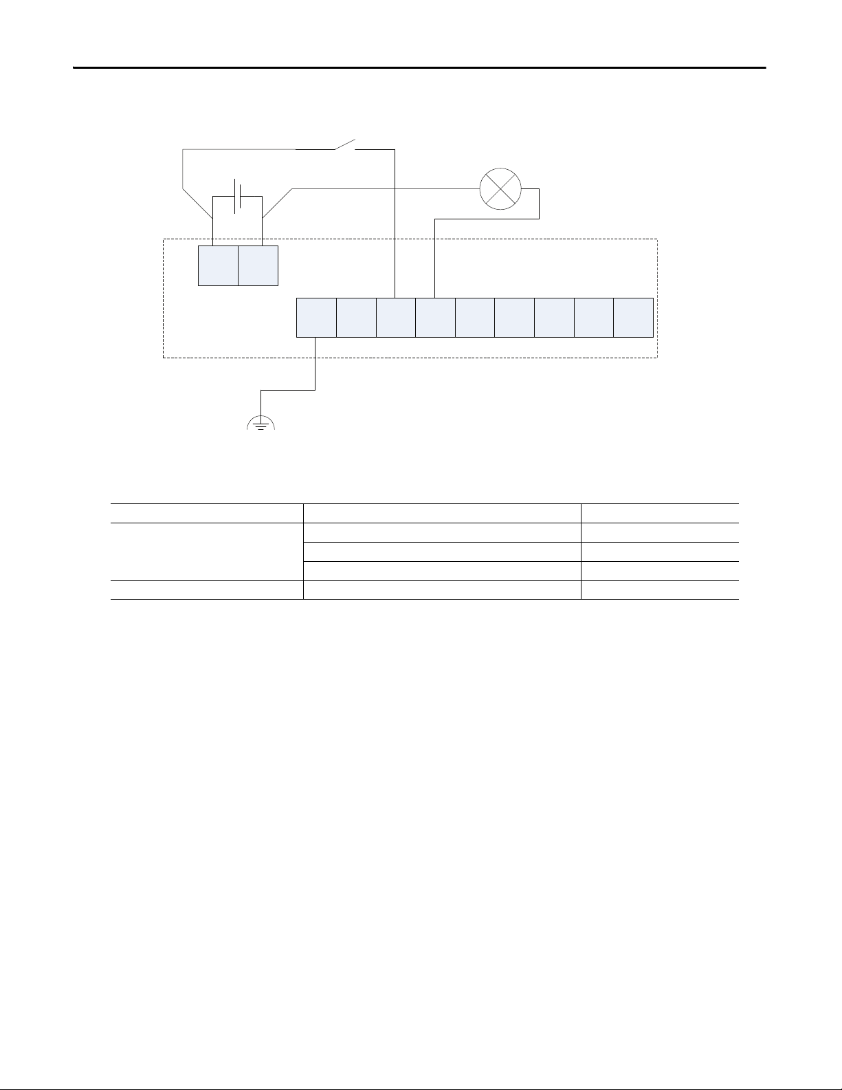
Controller Configuration Parameter Name Configuration Setting
Safety Input 0 Safety Input 0 Channel Mode Test Pulse from Test Output
Safety Input 0 Test Source Test Output 0
Dual-channel Safety Input 0/1 Mode Dual-channel Equivalent
Dual-channel Safety Input 0/1 Discrepancy Time 100 ms (application dependent)
Safety Input 1 Safety Input 1 Channel Mode Test Pulse from Test Output
Safety Input 1 Test Source Test Output 1
Safety Input 2 Safety Input 2 Channel Mode Used as standard input
Safety Input 2 Test Source Not Used
Dual-channel Safety Input 2/3 Mode Single Channel
Test Output 0 Test Output 0 Mode Pulse Test Output
Test Output 1 Test Output 1 Mode Pulse Test Output
Test Output 2 Test Output 2 Mode Power Supply Output
This example shows wiring and controller configuration when using the Guard
I/O module. If used in combination with the programs in a safety controller, this
wiring is Safety Category 4 in accordance with EN 954-1 wiring requirements.
Rockwell Automation Publication 1791ES-UM001D-EN-P - May 2013 39
Page 40

Chapter 4 Wiring Example s
Figure 17 - Two-hand Monitor
S11
I0 I2
FE
I1 I3
T1
S12
IN+ IN- T0
T2
T1
T1 T3
-
+
E1
31803-M
Controller Configuration Parameter Name Configuration Setting
Safety Input 0 Safety Input 0 Channel Mode Test Pulse from Test Output
Safety Input 0 Test Source Test Output 0
Dual Channel Safety Input 0/1 Mode Dual Channel Complementary
Dual Channel Safety Input 0/1 Discrepancy Time 100 ms (application dependent)
Safety Input 1 Safety Input 1 Channel Mode Test Pulse from Test Output
Safety Input 1 Test Source Test Output 1
Safety Input 2 Safety Input 2 Channel Mode Test Pulse from Test Output
Safety Input 2 Test Source Test Output 0
Dual Channel Safety Input 2/3 Mode Dual Channel Complementary
Dual Channel Safety Input 2/3 Discrepancy Time 100 ms (application dependent)
Safety Input 3 Safety Input 3 Channel Mode Test Pulse from Test Output
Safety Input 3 Test Source Test Output 1
Test Output 0 Test Output 0 Mode Pulse Test Output
Test Output 1 Test Output 1 Mode Pulse Test Output
This example shows wiring and controller configuration when using the Guard
I/O module. If used in combination with the programs of a safety controller, the
wiring is Category 4 in accordance with EN 954-1 wiring requirements.
40 Rockwell Automation Publication 1791ES-UM001D-EN-P - May 2013
Page 41

Figure 18 - Mode Select Switch
In + In -
T3M
PS1
FE I0 I1 T0 T1 I2 I3 T2 T7MI4 I5 T4 T5 I6 I7 T6
S1
S2
S3
S4
S5
44283
PS1: User 24V DC power supply
S1-S5: Switch
Wiring E xample s Chapter 4
Controller Configuration Parameter Name Configuration Setting
Safety Input 0 Safety Input 0 Channel Mode Safety Input
Safety Input 1 Safety Input 1 Channel Mode Safety Input
Safety Input 2 Safety Input 2 Channel Mode Safety Input
Safety Input 3 Safety Input 3 Channel Mode Safety Input
Safety Input 4 Safety Input 4 Channel Mode Safety Input
Safety Input 0 Test Source None
Dual Channel Safety Input 0/1 Mode Single Channel
Safety Input 1 Test Source None
Safety Input 2 Test Source None
Dual Channel Safety Input 2/3 Mode Single Channel
Safety Input 3 Test Source None
Safety Input 4 Test Source None
Dual Channel Safety Input 4/5 Mode Single Channel
Rockwell Automation Publication 1791ES-UM001D-EN-P - May 2013 41
Page 42

Chapter 4 Wiring Example s
In + In -
FE I0 I1 T0 T1 I2 I3 T2 T3M
PS1
L1
44284
PS1: User 24V DC power supply
L1: External Muting Lamp
Figure 19 - Muting Lamp Output
Controller Configuration Parameter Name Configuration Setting
Test Output 3 Test Output 3 Mode Muting Lamp Output
42 Rockwell Automation Publication 1791ES-UM001D-EN-P - May 2013
Page 43

Figure 20 - Limit Switch Dual-channel Inputs and a Manual Reset
44285
PS1: User 24V DC power supply
S!: Safety Limit Switch
(Positive Opening Mechanism)
S2: Safety Limited Switch
Close
Safety
Guard
PS1
In + In -
FE I0 I1 T0 T1 I2 I3 T2 T3M
S1
(N.C.)
Wiring E xample s Chapter 4
S2
(N.O.)
Controller Configuration Parameter Name Configuration Setting
Safety Input 0 Safety Input 0 Channel Mode Test Pulse from Test Output
Safety Input 0 Test Source Test Output 0
Dual-channel Safety Input 0/1 Mode Dual-channel Equivalent
Dual-channel Safety Input 0/1 Discrepancy Time 1000 ms (application dependent)
Safety Input 1 Safety Input 1 Channel Mode Test Pulse from Test Output
Safety Input 1 Test Source Test Output 1
Safety Input 2 Safety Input 2 Channel Mode Used as Standard Input
Safety Input 2 Test Source Not Used
Dual-channel Safety Input 2/3 Mode Single Channel
Test Output 0 Test Output 0 Mode Pulse Test Output
Test Output 1 Test Output 1 Mode Pulse Test Output
Test Output 2 Test Output 2 Mode Power Supply Output
S3
This example shows wiring and controller configuration when using the Guard
I/O module with limit switch dual-channel inputs and a manual reset. If used in
combination with the programs of a safety controller, the wiring is Category 4 in
accordance with EN 954-1 wiring requirements.
Rockwell Automation Publication 1791ES-UM001D-EN-P - May 2013 43
Page 44
Chapter 4 Wiring Example s
Controller Configuration Parameter Name Configuration Setting
Safety Input 1 Safety Input 1 Channel Mode Standard Input
Safety Input 1 Test Source None
Dual-channel Safety Input 0/1 Mode Single Channel
Test Pulse 0 Test Output 0 Mode 1 Standard Output
44287
PS1: User 24V DC power supply
L1: Lamp
S1: Switch
Figure 21 - Guard I/O module with limit switch dual-channel inputs and a manual reset
S1
PS1
In + In -
FE I0 I1 T0 T1 I2 I3 T2 T3M
L1
44 Rockwell Automation Publication 1791ES-UM001D-EN-P - May 2013
Page 45

Figure 22 - Dual-load Bipolar Outputs
IMPORTANT
In + In -
FE I0 I1 T0 T1 I2 I3 T2 T3M
PS1
FE
O0
P
O1
M
L- S+
O2
P
O3
M
L- S+
Out+Out
-
PS2
K2
K1
K1
K2
M
k2K1
44288
PS1, PS2: User 24V DC power supply
(A single power supply can be used
for both input and output power)
In order for the bipolar safety outputs to work correctly, you must connect the devices that are being controlled as
shown in this figure. Connection of devices directly to 24V DC, 0V DC, or Ground is strictly prohibited.
Wiring E xample s Chapter 4
Controller Configuration Parameter Name Configuration Setting
Safety Input 0 Safety Input 0 Channel Mode Test Pulse from Test Output
Safety Input 0 Test Source Test Output 0
Dual-channel Safety Input 0/1 Mode Single Channel
Test Output 0 Test Output 0 Mode Pulse Test Output
Safety Output 0 Safety Output 0 Channel Mode Safety Pulse Test
Safety Output 1 Safety Output 1 Channel Mode Safety Pulse Test
The example shows wiring and configuration when using the Guard I/O module
with solid state outputs in Dual-channel mode.
Note that all safety outputs of this Guard I/O module are permanently
configured for use as Dual-channel mode only. When used in combination with
the programs of the safety controller, this circuit configuration is Safety Category
4 in accordance with EN 954-1 requirements.
Rockwell Automation Publication 1791ES-UM001D-EN-P - May 2013 45
Page 46

Chapter 4 Wiring Example s
Notes:
46 Rockwell Automation Publication 1791ES-UM001D-EN-P - May 2013
Page 47

Chapter 5
Configure the I/O Modules by Using the Logix
Designer Application
Top ic Pa ge
Use Help 47
Add Modules to the I/O Configuration Tree 47
Use the Module Properties and General Dialogs 49
Work with the Safety Dialog 60
Work with the Input Configuration Dialog 62
Work with Test Output Configuration Dialog 62
Work with the Output Configuration Dialog 63
Save and Download the Module Configuration 65
Use Help
Add Modules to the I/O Configuration Tree
At the bottom of a dialog box, choose Help for information about how to
complete entries in the dialog box. At the bottom of a warning dialog box, choose
Help to get information about that specific error.
To add a module to the I/O configuration tree, follow these guidelines.
Rockwell Automation Publication 1791ES-UM001D-EN-P - May 2013 47
Page 48

Chapter 5 Configure the I/O Modules by Using the Logix Designer Application
1. From the I/O Configuration tree, right-click the EtherNet Bridge module,
as shown in the figure, and choose New Module.
The Select Module dialog box is displayed with a list that includes Safety.
48 Rockwell Automation Publication 1791ES-UM001D-EN-P - May 2013
Page 49

Configure the I/O Modules by Using the Logix Designer Application Chapter 5
A list of safety modules
appears here.
2. From the Select Module dialog box, choose the + next to Safety to see a list
of safety modules
Use the Module Properties and General Dialogs
3. From the Select Module dialog box, choose the appropriate module, such
as 1791ES-IB16, and OK at the bottom of the dialog box.
To use the Module Properties and General dialogs to configure a module, follow
these guidelines.
1. From the I/O configuration tree, double-click the module, such as the
1791ES-IB8XOBV4 module, to see the Module Properties dialog box.
2. From the Module Properties dialog box, complete entries for the General
dialog box.
a. For Name, type a unique name.
b. For IP Address, enter the IP address of the Guard I/O module.
Rockwell Automation Publication 1791ES-UM001D-EN-P - May 2013 49
Page 50

Chapter 5 Configure the I/O Modules by Using the Logix Designer Application
c. For Description, if desired, type a description.
For a detailed explanation of the safety network number (SNN), see the
GuardLogix Controller Systems Safety Reference Manual listed in the
Additional Resources on page 7
default provided by the Logix Designer application.
d. Click Change to see the Module Definition dialog box.
, noting that in most cases, you use the
e. From the Module Definition dialog box, select values to configure what
data and status tags to generate implicitly for the safety module, noting
that you can configure Input Data, Input Status, and Output Data.
Input Data Options
Choose from these options:
• Safety - Selecting Safety creates these tags for the target module:
– RunMode: Module mode
– ConnectionFaulted: Communication status
– Safety Data: Safety inputs from module
50 Rockwell Automation Publication 1791ES-UM001D-EN-P - May 2013
Page 51

Configure the I/O Modules by Using the Logix Designer Application Chapter 5
IMPORTANT
• Safety-Readback - This selection is not available for input-only safety
modules. Selecting Safety-Readback creates both safety and readback tags,
with readback indicating the presence of 24V on the output terminal.
Input Status Options
Choose from these options.
Status data is not SIL 3 data. Do not use status data to directly control a SIL 3
safety output.
• None - No status tags, only data for the inputs
Rockwell Automation Publication 1791ES-UM001D-EN-P - May 2013 51
Page 52

Chapter 5 Configure the I/O Modules by Using the Logix Designer Application
• Point Status-Muting - A muting status tag for test output T3/T7 with
point status for each input and output point
• Combined Status-Muting
– A single BOOL tag represents an AND of the status bits for all the
input points. For example, if any input channel has a fault, this bit goes
(1)
LO.
– A single BOOL tag represents an AND of the status bits for all the
output points.
(1)
– A muting status tag for test output T3/T7
(1) When using combined status, use explicit messaging to read individual point status for diagnostic purposes.
52 Rockwell Automation Publication 1791ES-UM001D-EN-P - May 2013
Page 53

Configure the I/O Modules by Using the Logix Designer Application Chapter 5
IMPORTANT
.
Output Data Options
Choose from these options.
The standard outputs on the module must not be used for safety purposes.
• None - Selecting None results in an input only connection to the module.
Inputs and status are read, but no outputs are written.
• Safety - Selecting Safety creates these safety tags and enables these outputs
for use in the safety task.
Rockwell Automation Publication 1791ES-UM001D-EN-P - May 2013 53
Page 54

Chapter 5 Configure the I/O Modules by Using the Logix Designer Application
• Test - Selecting Test creates these tags and enables the test outputs on the
module. These outputs are standard outputs and must not be used for
safety purposes.
• Combined - Selecting Combined creates these tags and enables all module
outputs - safety and test.
54 Rockwell Automation Publication 1791ES-UM001D-EN-P - May 2013
Page 55

Values and States of Tags
IMPORTANT
This table shows the values and states of the tags.
Table 5 - Values and States of Tags
Data Description
Input data Safety Input Data
SAFETY
Combined S afety In put Status
SAFETY
Individual Safety Input Status
SAFETY
Combined Safety Output Status
SAFETY
Individual Safety O utput Status
SAFETY
Muting Lamp Status
SAFETY
Output Readback
STANDARD
Individual Test Output Status
STANDARD
Indicates the ON/OFF status of each input circuit.
· ON: 1 OFF: 0
An AND of the status of all input circuits.
· All circuits are normal: 1
· An error was detected in one or more input circuits: 0
Indicates the status of each input circuit.
· Normal: 1 Fault (Alarm): 0
An AND of the status of all safety output circuits.
· All circuits are normal: 1
· An error has been detected in one or more output circuits: 0
Indicates the status of each safety output circuit.
· Normal: 1 Fault (Alarm): 0
Indicates the status when circuit T3 is configured as the muting lamp output.
· Normal: 1 Fault (Alarm): 0
Monitors the presence of 24V on the output circuit. Readback is ON (1) if 24V is on output terminal.
· ON: 1 OFF: 0
Indicates the status of each of the test output circuits.
· Normal: 1 Fault (Alarm): 0
Configure the I/O Modules by Using the Logix Designer Application Chapter 5
Output data Safety Output Data
SAFETY
Standard Output Data
STANDARD
Controls the safety output.
• ON: 1 OFF: 0
Controls the test output when Test Output mode is set to a standard output.
• ON: 1 OFF: 0
Safety denotes information the controller can use in safety-related functions.
Standard denotes additional information that must not be relied on for safety
functions.
Rockwell Automation Publication 1791ES-UM001D-EN-P - May 2013 55
Page 56

Chapter 5 Configure the I/O Modules by Using the Logix Designer Application
Work with the Safety Dialog
Read this for information about how to complete entries when you choose the
Safety tab.
1. From the Module Properties dialog box, choose the Safety tab to see the
Safety dialog box.
2. Configure Requested Packet Interval (RPI) and Configure Connection
Reaction Time Limit (CRTL) by following step 3.
56 Rockwell Automation Publication 1791ES-UM001D-EN-P - May 2013
Page 57

Configure the I/O Modules by Using the Logix Designer Application Chapter 5
IMPORTANT
We suggest that you keep the
Time-out Multiplier and Network
Delay Multiplier at their default
values of 2 and 200.
See GuardLogix Controllers User
Manual, listed in the Additional
Resources on page 7, for more
information about the CRTL.
3. From the Safety dialog box, choose Advanced to see the Advanced
Connection Reaction Time Limit Configuration dialog box.
Make sure that input RPI is set to match the need. The smallest input RPI
allowed is 6 ms. Selecting small RPI's consumes network bandwidth and
can cause nuisance trips because other devices can't get access to the
network.
As an example, a safety input module with only ESTOP switches
connected to it generally can work well with settings of 50…100 ms. An
input module with a light curtain guarding a hazard can need the fastest
response that is possible.
Selecting appropriate RPI's will result in a system with maximum (best)
performance.
Analyze each safety channel to determine what is appropriate. The default
timeout multiplier of 2 and network delay multiplier of 200 will create an input
connection reaction time limit of four times the RPI and an output connection
reaction limit of three times the RPI. Changes to these parameters must be
approved by a safety administrator.
Rockwell Automation Publication 1791ES-UM001D-EN-P - May 2013 57
Page 58

Chapter 5 Configure the I/O Modules by Using the Logix Designer Application
Connect ion
Faul ted
A connection status tag exists for every connection.
If the RPI and CRTL for the network are set appropriately, then this status
tag must always remain HI. Monitor all connection status bits to verify
that they are not going LO intermittently due to timeouts.
Configuration Ownership - Reset Ownership
The connection between the owner and the Guard I/O module is based on the
following:
• Guard I/O EtherNet IP address
• Guard I/O safety network number
• GuardLogix slot number
• GuardLogix safety network number
• Path from GuardLogix controller to Guard I/O module
• Configuration signature
If any of these change, the connection between the GuardLogix controller and
the Guard I/O module is lost, and the yellow yield in the project tree appears.
Reset ownership to reestablish the connection by using this procedure.
1. Open the safety I/O module properties.
2. Choose the Safety tab.
3. From the dialog box, choose Reset ownership.
58 Rockwell Automation Publication 1791ES-UM001D-EN-P - May 2013
Page 59

Configure the I/O Modules by Using the Logix Designer Application Chapter 5
Configuration Signature
The configuration signature is created by the Logix Designer application and
verified by the safety module. The configuration signature provides SIL 3
integrity of the configuration of a Guard I/O module.
• When a GuardLogix controller first connects to an unconfigured Guard I/
O module, the complete configuration is downloaded to the
I/O module.
• Any time the GuardLogix controller attempts to connect to a Guard
I/O module, if the configuration signatures are the same, then the
configuration does not need to be downloaded, because they already
match.
• Any time the GuardLogix controller attempts to connect to a Guard
I/O module and the signatures do not match, the module checks the IP
address and safety network number. If these are all correct, the controller
will attempt to configure the module.
Rockwell Automation Publication 1791ES-UM001D-EN-P - May 2013 59
Page 60

Chapter 5 Configure the I/O Modules by Using the Logix Designer Application
Work with the Input Configuration Dialog
See the table that shows typical safety input parameters, referring to Chapter 2
for related information.
Table 6 - Typical Safety Input Parameters
Parameter Name Value Description
Input Point Operation Type Single Channel Inputs are treated as single channel.
Dual-channel Equivalent Inputs are treated as a dual-channel pair. The channels must match (be equal) within the discrepancy
Dual-channel Complementary Inputs are treated as a dual-channel pair. The channels must disagree (be opposite) within the
Input Point Mode Not Used The input is disabled. It remains logic 0 if 24V is applied to the input terminal.
Safety Test Pulse Pulse testing is performed on this input circuit. A test source on the 1791ES module must be used as
Safety A safety input is connected but there is no requirement for the 1791ES module to perform a pulse test
Standard A standard device, such as a reset switch, is connected. This point cannot be used in dual channel
Safety Input Test Source None If pulse testing is being performed on an input point, then the test source that is sourcing the 24V for
Tes t Out pu t 0
Tes t Out pu t 1
Tes t Out pu t 2
Tes t Out pu t 3
Test Output 4…15
Input Delay Time
Off -> On
Input Delay Time
On -> Off
Safety Input Error Latch Time 0…65,530 ms (in increments
(1) There are eight test outputs on 1791ES-IB8XOBV4 modules.
0…126 ms (in increments of
6ms)
0…126 ms (in increments of
6ms)
of 10 ms)
(1)
time or a fault is generated.
discrepancy time or a fault is generated.
the 24V source for this circuit. The test source is configured by using the test source pulldown. The
pulse test will detec t shorts to 24V and channel-to -channel shorts to other inputs.
on this c ircuit. An example is a safety device that performs its own pulse tests on the input wires, such
as a light curtain.
operation.
the input circuit must be selected.
If the incorrect test source is entered, the result is pulse test failures on that input circuit.
Filter time is for OFF to ON transition. Input must be high after input delay has elapsed before it is set
logic 1.
Filter time is ON to OFF transition. Input must be low after input delay has elapsed before it is set logic
0.
Default is 1000 ms. The purpose for latching input errors is to make sure that intermittent faults that
can only exist for a few milliseconds are latched long enough to be read by the controller. The amount
of time to latch the error must be based on the RPI, the safety task watchdog, and other applicationspecific variables.
60 Rockwell Automation Publication 1791ES-UM001D-EN-P - May 2013
Page 61

Configure the I/O Modules by Using the Logix Designer Application Chapter 5
Follow this procedure to complete entries from the Input Configuration dialog
box that you see when, from the top of the Module Properties dialog box, choose
Input Configuration.
1. For Point Operation Type, choose one of these values and a value for
Discrepancy Time if set to Equivalent or Complementary:
• Single
Inputs are treated as single channels. Note that in many cases, dualchannel safety inputs are configured as two individual single channels.
This does not affect pulse testing because it is handled on an individual
channel basis.
(1)
• Equivalent
Inputs are treated as a dual-channel pair. The channels must match
within the discrepancy time or an error is generated.
• Complementary
(1)
Inputs are treated as a dual-channel pair. They must be in opposite
states within the discrepancy time or an error is generated.
(1) Be aware that configuring discrepancy time on safety I/O modules masks input inconsistent faults from the GuardLogix safety
instructions. Status can be read by GuardLogix to obtain this fault information.
Rockwell Automation Publication 1791ES-UM001D-EN-P - May 2013 61
Page 62

Chapter 5 Configure the I/O Modules by Using the Logix Designer Application
2. For Point Mode, choose one of these values for each point, referring to the
Safety Input Parameters table for additional information:
• Not Used - Safety input channel is disabled
• Safety Pulse Test - Safety input is configured for pulse test operation
• Safety - The safety input is used with a safety field device
• Standard - Safety input has a standard field device wired to it
3. Complete entries, noting the following:
• For each safety input on the module, you can define if the input will be
pulse tested. If the inputs is pulse tested, select which test source to use.
• Off -> On and On -> Off delay times can be configured per channel
with each channel specifically tuned to match the characteristics of the
field device for maximum performance.
• Input Error Latch Time is the time the module holds an error to make
sure the controller can detect it. This provides you more reliable
diagnostics and enhances the chances that a nuisance error is detected.
4. Click OK at the bottom of the dialog box or a tab at the top of the dialog
box.
Work with Test Output Configuration Dialog
Table 7 - Configuring Test Outputs
Parameter Name Value Description Default
Test Output Mode Not Used The test output is disabled. Not Used
Standard The output point is enabled for use by the GuardLogix controller.
Pulse Test The test output is being used as a pulse test source.
Power Supply A constant 24V is placed on the output terminal. It can be used to provide power to a field device.
Muting Lamp Output
(Terminal T3/T7 only)
Read this for information about how to work with the Test Output
Configuration dialog box, referring to the table that provides information on
configuring test outputs.
An indicator lamp is connected to the output. Whe n this lamp is energized, a burned-out bulb, broken
wire, or short to GND error condition can be detected. Typically, the lamp is an indicator used in light
curtain applications.
62 Rockwell Automation Publication 1791ES-UM001D-EN-P - May 2013
Page 63

Configure the I/O Modules by Using the Logix Designer Application Chapter 5
Complete entries on the Test Output dialog box, referring to the figure.
Work with the Output Configuration Dialog
Read this for a guideline on how to configure safety outputs by using the
information in the table and completing the entries referring to the figure.
Table 8 - Guidelines for Configuring Safety Outputs
Parameter Name Value Description Default
Point Operation Type Dual The 1791ES module treats the outputs as a pair. It always sets them HI to LO as a matched pair.
Point Mode Not Used The output is disabled. Not Used
Safety The output point is enabled, and it does not perform a pulse test on the output.
Safety Pulse Test The output point is enabled and performs a pulse test on the output.
Output Error Latch
Time
0…65,530 ms (in
increments of 10 ms)
Safety logic must set both of these outputs ON or OFF at the same time or the module will declare a channel fault.
When the output is energized, the output pulses LO briefly. The pulse test detects if 24V remains on the output
terminal during t his LO pulse due to a short to 24V or if the output is shorted to another output te rminal.
The purpose for latching output errors is to make sure that intermittent faults that can only exist for a few
milliseconds are latched long enough to be read by the controller. The amount of time to latch the errors is based
on the RPI, the safety task watchdog, and other application-specific variables.
Dual-channel
1000 ms
Rockwell Automation Publication 1791ES-UM001D-EN-P - May 2013 63
Page 64

Chapter 5 Configure the I/O Modules by Using the Logix Designer Application
Follow this procedure to complete entries from the Output Configuration dialog
box.
1. For Point Operation, all safety outputs are Dual mode only.
• The Guard I/O module always sets them high or low as a pair.
• You must always match the two outputs as a pair in software as well.
2. For Point Mode, select Not Used, Safety, or Safety Pulse Test, referring to
the Safety Output Parameters table for additional information.
3. Select a value for Output Error Latch Time. Output Error Latch Time is
the time the module holds an error to make sure the controller can detect
it. This provides you more reliable diagnostics and enhances the changes
that a nuisance error is detected.
4. Click Apply from the bottom of the dialog box.
64 Rockwell Automation Publication 1791ES-UM001D-EN-P - May 2013
Page 65

Configure the I/O Modules by Using the Logix Designer Application Chapter 5
Save and Download the Module Configuration
We recommend that after a module is configured you save your work.
If after downloading the program the MS and NS LED indicators on the Guard
I/O module are not both solid green, this can be due to loss of ownership. The
ownership is based on the following:
• Guard I/O EtherNet IP address
• Guard I/O safety network number
• GuardLogix slot number
• GuardLogix safety network number
• Path from GuardLogix controller to Guard I/O module
• Configuration signature
If any of these change, the connection between the GuardLogix controller and
the Guard I/O module is lost, and the yellow yield in the project tree appears.
Reset ownership to reestablish the connection by using this procedure.
1. Open the safety I/O module properties.
2. Choose the Safety tab.
3. From the dialog box, choose Reset ownership.
Rockwell Automation Publication 1791ES-UM001D-EN-P - May 2013 65
Page 66

Chapter 5 Configure the I/O Modules by Using the Logix Designer Application
Notes:
66 Rockwell Automation Publication 1791ES-UM001D-EN-P - May 2013
Page 67

Interpret Module Indicators
24V DC Input Power Indicator
Module Status Indicator
Configuration Lock Indicator
24V DC Output Power Indicator
(1791ES-IB8XOBV4 modules only)
I0…I15 - Safety Input Status Indicator
T0…T15 - Test Output Status indicator
00…07 - Safety Output Status Indicator (1791ES-IB8XOBV4 module)
Network Status Indicator
Network
Activity
Indicator
Top ic Pa ge
Module Indicators 67
Configuration Lock Indicator 69
Chapter 6
Module Indicators
See the figure and tables for information on how to interpret LED module
indicators.
Figure 23 - Module Indicators
Table 9 - 24V DC Input Power Indicator
State Status Description Recommended Action
Off No power No power is applied. Apply power to this section.
Solid green Normal operation The applied voltage is within specifications. None.
Solid yellow Input power out of specification The input power is out of specification. Check your connectors, wiring, and voltages.
Rockwell Automation Publication 1791ES-UM001D-EN-P - May 2013 67
Page 68

Chapter 6 Interpret Module Indicators
Table 10 - 24V DC Output Power Indicator
State Status Description Recommended Action
Off No power No power is applied. Apply power to this section.
Solid green Normal operation The applied voltage is within specifications. None.
Solid yellow Output power out of specification The output power is out of specification. Check your connectors, wiring, and voltages.
Table 11 - Module Status Indicator
State Status Description Recommended Action
Off No power No power is applied to the power connector. Apply power to this connector.
Solid green Normal operation The module is operating normally. None.
Solid red Unrecoverable fault The module detected an unrecoverable fault. Cycle power to the module. If problem persists,
Flashing red and
green
Flashing green Idle Idle, waiting for connection from scanner. Establish connection.
Flashing red Recoverable fault The module has detected a recoverable fault. Cycle power to the module or reset the module.
Module is unconfigured Module needs commissioning due to missing, incomplete, or
incorrect configuration.
Device in self test The module is performing its power-cycle diagnostic tests. Wait for the module to complete its power-cycle
User-initiated firmware update in progress User-initiated firmware update is in progress. Wait for firmware update to complete.
replace the module.
Reconfigure the module. For additional
information, inspect Network Status indicator.
diagnostics.
Table 12 - Network Status Indicator
State Status Description Recommended Action
Off Module not online The module does not have an IP address. Verify your network is working properly.
Flashing green Module online with no connections in
Solid green Module online with connections in
Flashing red One or more I/O connections in timed-out
Solid red Critical link failure The module detected an error that prevents it from communicating on the
Flashing red
and green
established state
established state
state
User-initiated firmware update User-initiated firmware update is in progress. Wait for firmware update to complete.
Self test The module is performing its power-cycle diagnostic test. Wait for the module to complete its power-
The module has acquired an IP address, but no connections are established. Verify your network and module
The module is operating normally. None.
The module detected a recoverable network fault. Verify your network and module
network, such as duplicate IP address has been detected.
configuration.
configuration.
Cycle power to the module. Check network
IP addressing.
cycle diagnostics.
68 Rockwell Automation Publication 1791ES-UM001D-EN-P - May 2013
Page 69

Interpret Module Indicators Chapter 6
Table 13 - Network Activity Indicator
State Status Recommended Action
Off No link established Establish link.
Flashing Green Transmit or receive activity None.
Steady Green Link established None.
Table 14 - Safety Input Status Indicator
State Status Description Recommended Action
Off Safety input off The safety input is off or the channel is configured for not used. Turn the safety input on or reconfigure the
Solid yellow Safety input on The safety input is on. None.
Solid red Fault detected A fault in the external wiring or input circuit detected. Check configuration, field wiring, and devices. If no
Flashing red Partner fault detected A fault in the partner input circuit of a dual-input configuration
detected.
channel, if desired.
problem found, replace module.
Check the field wiring and verify your configuration
for the partner circuit. If no problem found, replace
module.
Table 15 - Test Output Status Indicator
State Status Description Recommended Action
Off Test output off The test output is off or the channel is configured for not used. Turn the test output on or reconfigure the channel, if
Solid yellow Output on Output is on. None.
Solid red Fault detected A fault in the external wiring or input circuit detected. Check field wiring. If no problem found, replace
desired.
module. For outputs configured for muting could
indicate undercurrent or burned-out lamp.
Table 16 - Safety Output Status Indicator (1791ES-IB8XOBV4 only)
State Status Description Recommended Action
Off Safety output off The safety output is off or the channel is configured for not used. Turn the safety output on or reconfigure the channel, if
Solid yellow Safety output on The safety output is on. None.
Solid red Fault detected A fault in the output circuit was detected. Check the circuit wiring and end device. If no problem
Both tags in a dual channel circuit do not have the same value. Make sure logic is driving tag values to the same state
Flashing red Partner fault detected A fault in the partner output circuit of a dual output configuration
Configuration Lock Indicator
was detected.
Configuration lock indicator is not supported by the Logix Designer application.
desired.
found, replace module.
(off or on).
Check the circuit wiring and end device of t he partner. If
no problem found, replace module.
Rockwell Automation Publication 1791ES-UM001D-EN-P - May 2013 69
Page 70

Chapter 6 Interpret Module Indicators
Notes:
70 Rockwell Automation Publication 1791ES-UM001D-EN-P - May 2013
Page 71

Appendix A
Get Diagnostic Status from Modules by Using
Explicit Messaging
Top ic Pa ge
Work with 1791ES-IB8XOBV4 Modules 72
Work with 1791ES-IB16 Modules 77
I/O Data Supported by Each Module 81
I/O Assembly and Reference Data 83
Explicit Messages 88
This appendix provides information about how to use CIP Generic Message
instructions (sometimes called explicit messaging ) to get diagnostic status
information from the modules.
You can implicitly obtain individual point status of the Guard I/O module from
the Module Definition dialog box by choosing Pt. Status from the Input Status
pull-down menu.
Rockwell Automation Publication 1791ES-UM001D-EN-P - May 2013 71
Page 72

Appendix A Get Diagnostic Status from Modules by Using Explicit Messaging
Another choice is to obtain overall status implicitly from the Module Definition
di alo g box by choo sing Combined Status f rom the Input Status p ull-do wn menu.
Work with 1791ES-IB8XOBV4 Modules
If the Combined Status changes, use explicit messaging to obtain the point level
status.
To work with 1791ES-IB8XOBV4 modules, follow this procedure.
1. In the Module Definition dialog box, from the Input Status pull-down
menu, choose Combined Status.
72 Rockwell Automation Publication 1791ES-UM001D-EN-P - May 2013
Page 73
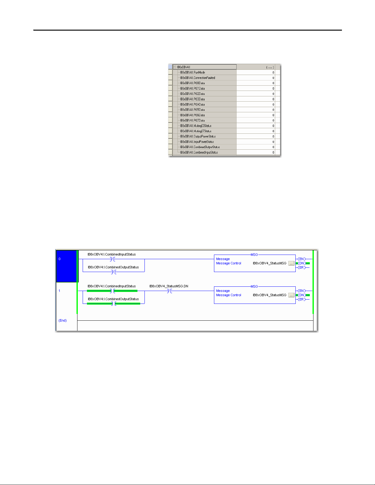
Get Diagnostic Status from Modules by Using Explicit Messaging Appendix A
This creates a two-byte input assembly, as shown for the 1791ESIB8XOBV4 module.
2. Use the CombinedInputStatus and CombinedOutputStatus bits to detect
if one or more of the I/O points on the module have a fault.
• If any input or output status bit goes to a value of 0 (0=error, 1=no
error), use the InputStatus and OutputStatus bits to condition your
msg rungs as follows.
• Note that the second rung can be used to read the status on mode
transition and once a fault is detected, continue reading until the fault is
corrected.
• Place these rungs in the standard task.
Rockwell Automation Publication 1791ES-UM001D-EN-P - May 2013 73
Page 74

Appendix A Get Diagnostic Status from Modules by Using Explicit Messaging
Reference the figures below that show the MSG instruction parameters for
reading Instance 852 from the 1791ES-IB8XOBV4 module.
354 (852) 1791ES-
IB8XOBV4
Safety and
Standard
Instance 852 (354 Hex) is 5 bytes in length, so the Destination Tag
MSGdata must be at least 5 bytes in length to hold this data. The size is
DINT[2] or 8 bytes.
See the figure that shows the layout of Instance 852 (354 Hex).
0 Safet y Input
7
1Safety Input
7 S t a t u s
2Safety
Output 7
Status
3Safety
Output 7
Monitor
4 Reser ved Reserved Input
Safety Input 6Safety
Safety Input
6 Status
Safety
Output 6
Status
Safety
Output 6
Monitor
Input 5
Safety
Input 5
Status
Safety
Output 5
Status
Safety
Output 5
Monitor
Power
Error
(1)
Safety Input 4Safety
Safety Input
4 Status
Safety
Output 4
Status
Safety
Output 4
Monitor
Output
Power
(1)
Error
Input 3
Safety
Input 3
Status
Safety
Output 3
Status
Safety
Output 3
Monitor
Reserved Reser ved Muting
Safety Input 2Safety
Safety Input
2 Status
Safety
Output 2
Status
Safety
Output 2
Monitor
Input 1
Safety
Input 1
Status
Safety
Output 1
Status
Safety
Output 1
Monitor
Lamp 7
Status
Safety Input
0
Safety Input
0 Status
Safety
Output 0
Status
Safety
Output 0
Monitor
Muting
Lamp 3
Status
74 Rockwell Automation Publication 1791ES-UM001D-EN-P - May 2013
Page 75

Get Diagnostic Status from Modules by Using Explicit Messaging Appendix A
From the top of the Message Configuration dialog box, choose the
Communication tab. This dialog box requires the path to the module.
Click Browse to browse to the module that the MSG will read.
From the top of the Message Configuration dialog box, choose Tag to see
this dialog box.
Rockwell Automation Publication 1791ES-UM001D-EN-P - May 2013 75
Page 76

Appendix A Get Diagnostic Status from Modules by Using Explicit Messaging
When the explicit message reads the data from the 1791ES-IB8XOBV4
module, the data appears in the MSGdata tags as shown.
The first 32 bits of the instance are in MSGdata[0].0…31, and the final 8
bits are in MSGdata[1].0…7. These 40 bits must be mapped according to
Instance 852. An easy method to do this mapping is to create a user
defined tag (UDT) for Instance 852. Once complete, it appears as follows.
76 Rockwell Automation Publication 1791ES-UM001D-EN-P - May 2013
Page 77

Get Diagnostic Status from Modules by Using Explicit Messaging Appendix A
Work with 1791ES-IB16 Modules
To work with 1791ES-IB16 modules, follow this procedure.
1. In the Module Definition dialog box, from the Input Status pull-down
menu, choose Combined Status.
This creates a three-byte input assembly, as shown, for the 1791ES-IB16
module.
Rockwell Automation Publication 1791ES-UM001D-EN-P - May 2013 77
Page 78

Appendix A Get Diagnostic Status from Modules by Using Explicit Messaging
2. Use the CombinedInputStatus bit to detect if one or more of the I/O
points on the module have a fault.
• If any input status bits go to a value of 0 (0 = bad; 1 = good), use an
explicit message to determine which individual data points have
faulted.
• Note that you can use the second rung to read the status on mode
transition and once a fault is detected, continue reading until the fault is
corrected.
• Place these rungs in the standard task.
See the figures that show the MSG instruction parameters for reading
Instance 869 from the 1791ES-IB16 module. See Appendix
C of this
manual for a layout of possible instances.
Instance 869 (365 Hex) is 7 bytes in length, so the Destination Tag
IB16MSGdata must be at least 7 bytes in length to hold this data. The size
is DINT[2] or 8 bytes.
78 Rockwell Automation Publication 1791ES-UM001D-EN-P - May 2013
Page 79

Get Diagnostic Status from Modules by Using Explicit Messaging Appendix A
The layout of Instance 869 (365 Hex) is as follows.
365 1791ES-
IB16
Safety and
Standard
0Safety Input 7Safety Input 6Safety
1Safety Input 15Safety Input 14Safety
2Safety Input
7
Status
3Safety Input
15
Status
4Safety
Output 7
Status
5Safety
Output 15
Status
6 Reserved Reserved Input
Safety Input
6
Status
Safety Input
14
Status
Safety
Output 6
Status
Safety
Output 14
Status
Input 5
Input 13
Safety
Input 5
Status
Safety
Input 13
Status
Safety
Output 5
Status
Safety
Output 13
Status
Power
Err
or
From the top of the Message Configuration dialog box, choose the
Communication tab. This dialog box requires the path to the module.
Click Browse to browse to the module that the MSG will read.
Safety
Input 4
Safety
Input 12
Safety
Input 4
Status
Safety
Input 12
Status
Safety
Output 4
Status
Safety
Output 12
Status
Output
Power
(1)
Error
Safety
Input 3
Safety
Input 11
Safety
Input 3
Status
Safety
Input 11
Status
Safety
Output 3
Status
Safety
Output 11
Status
Muting
Lamp 15
(1)
Status
Safety
Input 2
Safety
Input 10
Safety
Input 2
Status
Safety
Input 10
Status
Safety
Output 2
Status
Safety
Output 10
Status
Muting
Lamp 11
Status
Safety
Input 1
Safety
Input 9
Safety
Input 1
Status
Safety
Input 9
Status
Safety
Output 1
Status
Safety
Output 9
Status
Muting
Lamp 7
Status
Safety
Input 0
Safety
Input 8
Safety
Input 0
Status
Safety
Input 8
Status
Safety
Output 0
Status
Safety
Output 8
Status
Muting
Lamp 3
Status
Rockwell Automation Publication 1791ES-UM001D-EN-P - May 2013 79
Page 80

Appendix A Get Diagnostic Status from Modules by Using Explicit Messaging
From the top of the Message Configuration dialog box, click Tag to see
this dialog box.
When the explicit message reads the data from the 1791ES-IB16 module,
the data appears in the MSGdata tags as shown.
80 Rockwell Automation Publication 1791ES-UM001D-EN-P - May 2013
Page 81
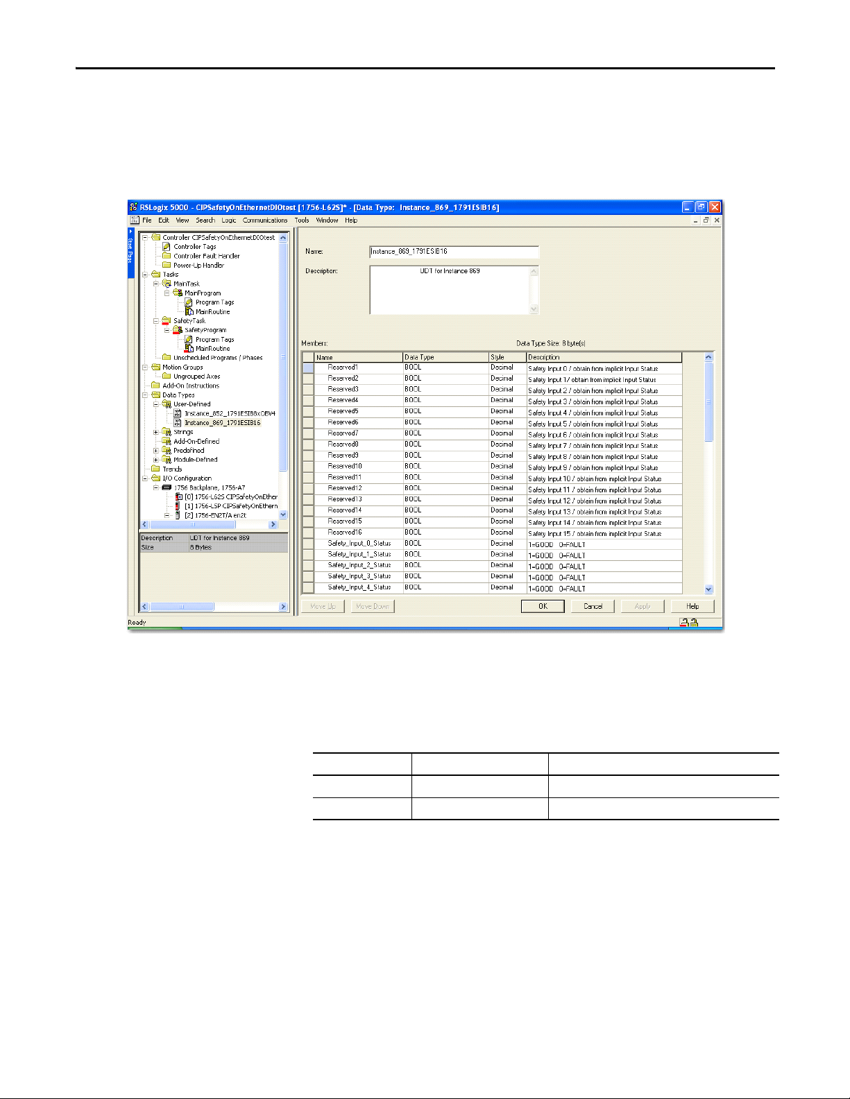
Get Diagnostic Status from Modules by Using Explicit Messaging Appendix A
The first 32 bits of the instance are in IB16MSGdata[0].0…31, and the
final 24 bits are in IB16MSGdata[1].0…23. Map these 56 bits according to
Instance 869. An easy method to do this mapping is to create a user
defined tag (UDT) for Instance 869. Once you complete this, it appears
as follows.
I/O Data Supported by Each Module
See the table that shows a summary of default I/O data by module.
Table 17 -Default I/O Data
Safety Connection Assembly Instance (Hex)
1791ES-IB16 Safety 225 and 23
1791ES-IB8XOBV4 Safety 204 and 234
The tables show the I/O data supported by each module. Refer to I/O Assembly
Data for data arrangements.
Rockwell Automation Publication 1791ES-UM001D-EN-P - May 2013 81
Page 82

Appendix A Get Diagnostic Status from Modules by Using Explicit Messaging
For I/O data, safety connections for up to four items, including one output, can
be allocated for the master unit. Also, standard connections for up to two items
can be allocated for the master unit.
Table 18 - 1791ES-IB8XOBV4 Modules
Input Data Input Status Assembly Instance
Safety None 204
Safety - Readback Point Status - Muting 354
Output Data Assembly Instance
Safety 234
Tes t 2 2
Combined 2C4
None C7
(1) Default for output data.
(2) Default for input data.
(2)
Point Status - Muting 334
Combined Status - Muting 324
Point Status - Muting - Test Output 374
(1)
Table 19 - 1791ES-IB16 Modules
Input Data Input Status Assembly Instance
Safety None 205
Point Status - Muting 335
Point Status - Muting - Test Output 365
Combined Status - Muting 315
Point Status 225
Output Data Assembly Instance
Tes t 23
None C7
82 Rockwell Automation Publication 1791ES-UM001D-EN-P - May 2013
Page 83

Get Diagnostic Status from Modules by Using Explicit Messaging Appendix A
I/O Assembly and Reference Data
See the tables for I/O assembly and reference data. The bits in the tag definitions
of the Logix Designer application are different than those shown in the following
section. The following defines the name associations for clarification with the
programming software.
Table 20 - Bit Definitions and Logix Designer Tag Names
Bit Definitions Logix Designer Application Tag Name
Safety Input 0 Pt00Data
Safety Input 15 Pt15Data
Safety Input 0 Status Pt00InputStatus
Safety Input 15 Status Pt15InputStatus
Safety In Status InputStatus
Muting Lamp Status MutingStatus
Safety Output 0 Pt00Data
Safety Output 7 Pt07Data
Standard Output 0 Test00Data
Standard Output 15 Test15Data
Safety Output 0 Status Pt00OutputStatus
Safety Output 7 Status Pt07OutputStatus
Safety Out Status OutputStatus
Safety Output 0 Monitor Pt00Readback
Safety Output 7 Monitor Pt07Readback
Test Output 0 Status Pt00TestOutputStatus
Test Output 15 Status Pt15TestOutputStatus
Table 21 - Input Data
Instance
Hex
(Decimal)
204 (516) 1791ES-
205 (517) 1791ES-
224 (548) 1791ES-
Module Connection
IB8XOBV4
IB16
IB8XOBV4
Type
Safety and
Standard
Safety and
Standard
Safety and
Standard
See these tables for reference data concerning input and output data.
Byte Bit 7 Bit 6 Bit 5 Bit 4 Bit 3 Bit 2 Bit 1 Bit 0
0Safety Input 7Safety Input 6Safety
0Safety Input 7Safety Input 6Safety
1Safety Input 15Safety Input 14Safety
0Safety Input 7Safety Input 6Safety
1Safety Input
7
Status
Safety Input
6
Status
Input 5
Input 5
Input 13
Input 5
Safety
Input 5
Status
Safety Input 4Safety
Safety Input 4Safety
Safety Input 12Safety
Safety Input 4Safety
Safety Input
4
Status
Input 3
Input 3
Input 11
Input 3
Safety
Input 3
Status
Safety Input 2Safety
Safety Input 2Safety
Safety Input 10Safety
Safety Input 2Safety
Safety Input
2
Status
Input 1
Input 1
Input 9
Input 1
Safety
Input 1
Status
Safety Input
0
Safety Input
0
Safety Input
8
Safety Input
0
Safety Input
0
Status
Rockwell Automation Publication 1791ES-UM001D-EN-P - May 2013 83
Page 84

Appendix A Get Diagnostic Status from Modules by Using Explicit Messaging
Table 21 - Input Data (continued)
Instance
Module Connection
Hex
(Decimal)
225 (549) 1791ES-
IB16
300 (768) 1791ES-
IB16
301 (769) 1791ES-
IB8XOBV4
315 (789) 1791ES-
IB16
324 (804) 1791ES-
IB8XOBV4
334 (820) 1791ES-
IB8XOBV4
335 (821) 1791ES-
IB16
Type
Byte Bit 7 Bit 6 Bit 5 Bit 4 Bit 3 Bit 2 Bit 1 Bit 0
Safety and
Standard
0Safety Input 7Safety Input 6Safety
Input 5
1Safety Input 15Safety Input 14Safety
Input 13
2Safety Input
7
Status
3Safety Input
15
Status
Safety Input
6
Status
Safety Input
14
Status
Safety
Input 5
Status
Safety
Input 13
Status
Safety Input 4Safety
Input 3
Safety Input 12Safety
Input 11
Safety Input
4
Status
Safety Input
12
Status
Safety
Input 3
Status
Safety
Input 11
Status
Safety Input 2Safety
Input 1
Safety Input 10Safety
Input 9
Safety Input
2
Status
Safety Input
10
Status
Safety
Input 1
Status
Safety
Input 9
Status
Safety Input
0
Safety Input
8
Safety Input
0
Status
Safety Input
8
Status
Standard Only 0 Reserved Reserved Reserved Reser ved Reserved Reserved Reserved Input Power
Error
Standard Only 0 Reserved Reserved Reserved Reser ved Reserved Reserved Output
Power
Input Power
Error
Error
Safety and
Standard
Safety and
Standard
Safety and
Standard
Safety and
Standard
0Safety Input
7
1Safety Input
15
Sta
tus
2Combined
Safety In
Status
0Safety Input
7
1Combined
Safety In
Status
0Safety Input
7
1Safety Input
7
Status
Safety Input 6Safety
Input 5
Safety Input
14
Status
Safety
Input 13
Status
Reserved Input
Power
Error
Safety Input 6Safety
Input 5
Combined
Safety Out
Status
Input
Power
Error
Safety Input 6Safety
Input 5
Safety Input
6
Status
Safety
Input 5
Status
2 Reser ved Reserved Input
Power
Error
0Safety Input 7Safety Input 6Safety
Input 5
1Safety Input 15Safety Input 14Safety
Input 13
2Safety Input
7
Status
3Safety Input
15
Status
Safety Input
6
Status
Safety Input
14
Status
Safety
Input 5
Status
Safety
Input 13
Status
4 Reser ved Reserved Input
Power
Error
Safety Input 4Safety
Safety Input
12
Status
Reserved Muting
(1)
Safety Input 4Safety
Output
Power
(1)
Error
Safety Input 4Safety
Safety Input
4 Status
Output
Power
(1)
Error
Safety Input 4Safety
Safety Input 12Safety
Safety Input
4
Status
Safety Input
12
Status
Reserved Muting
(1)
Input 3
Safety
Input 11
Status
Lamp 15
Status
Safety Input
10
Status
Muting
Lamp 11
Status
Input 1
Safety
Input 9
Status
Muting
Lamp 7
Status
Safety Input 2Safety
Safety Input 2Safety
Input 3
Input 1
Reserved Reser ved Muting
(1)
Lamp 7
Status
Safety Input 2Safety
Input 3
Safety
Input 3
Status
Safety Input
2 Status
Input 1
Safety
Input 1
Status
Reserved Reser ved Muting
(1)
Lamp 7
Status
Safety Input 2Safety
Input 3
Input 1
Safety Input 10Safety
Input 11
Safety
Input 3
Status
Safety
Input 11
Status
Lamp 15
Status
Safety Input
2
Status
Safety Input
10
Status
Muting
Lamp 11
Status
Input 9
Safety
Input 1
Status
Safety
Input 9
Status
Muting
Lamp 7
Status
Safety Input
0
Safety Input
8
Status
Muting
Lamp 3
Status
Safety Input
0
Muting
Lamp 3
Status
Safety Input
0
Safety Input
0 Status
Muting
Lamp 3
Status
Safety Input
0
Safety Input
8
Safety Input
0
Status
Safety Input
8
Status
Muting
Lamp 3
Status
84 Rockwell Automation Publication 1791ES-UM001D-EN-P - May 2013
Page 85

Table 21 - Input Data (continued)
Get Diagnostic Status from Modules by Using Explicit Messaging Appendix A
Instance
Module Connection
Hex
(Decimal)
344 (836) 1791ES-
IB8XOBV4
354 (852) 1791ES-
IB8XOBV4
364 (868) 1791ES-
IB8XOBV4
Type
Safety and
Standard
Safety and
Standard
Safety and
Standard
Byte Bit 7 Bit 6 Bit 5 Bit 4 Bit 3 Bit 2 Bit 1 Bit 0
0 Safet y Input
7
1Safety Input
7
St at us
2Safety
Output 7
Status
3 Reser ved Reserved Input
0 Safet y Input
7
1Safety Input
7 S t a t u s
2Safety
Output 7
Status
3Safety
Output 7
Monitor
4 Reser ved Reserved Input
0Safety Input
7 S t a t u s
1Safety
Output 7
Status
2 Test Output
7 Status
Safety Input 6Safety
Input 5
Safety Input
6
Status
Safety
Output 6
Status
Safety
Input 5
Status
Safety
Output 5
Status
Power
Error
Safety Input 6Safety
Input 5
Safety Input
6 Status
Safety
Input 5
Status
Safety
Output 6
Status
Safety
Output 6
Monitor
Safety
Output 5
Status
Safety
Output 5
Monitor
Power
Error
Safety Input
6 Status
Safety
Input 5
Status
Safety
Output 6
Status
Tes t O utp ut
6 Status
Safety
Output 5
Status
Tes t O u tp ut
5 Status
Safety Input 4Safety
Safety Input
4
Status
Safety
Output 4
Status
Output
Power
(1)
Error
Safety Input 4Safety
Safety Input
4 Status
Safety
Output 4
Status
Safety
Output 4
Monitor
Output
Power
(1)
Error
Safety Input
4 Status
Safety
Output 4
Status
Tes t Out pu t
4 Status
Input 3
Safety
Input 3
Status
Safety
Output 3
Status
Reserved Reser ved Muting
(1)
Input 3
Safety
Input 3
Status
Safety
Output 3
Status
Safety
Output 3
Monitor
Reserved Reser ved Muting
(1)
Safety
Input 3
Status
Safety
Output 3
Status
Tes t O u tp ut
3 Status
Safety Input 2Safety
Input 1
Safety Input
2
Status
Safety
Output 2
Status
Safety
Input 1
Status
Safety
Output 1
Status
Lamp 7
Status
Safety Input 2Safety
Input 1
Safety Input
2 Status
Safety
Input 1
Status
Safety
Output 2
Status
Safety
Output 2
Monitor
Safety
Output 1
Status
Safety
Output 1
Monitor
Lamp 7
Status
Safety Input
2 Status
Safety
Input 1
Status
Safety
Output 2
Status
Tes t O utp ut
2 Status
Safety
Output 1
Status
Tes t
Output 1
Safety Input
0
Safety Input
0
Status
Safety
Output 0
Status
Muting
Lamp 3
Status
Safety Input
0
Safety Input
0 Status
Safety
Output 0
Status
Safety
Output 0
Monitor
Muting
Lamp 3
Status
Safety Input
0 Status
Safety
Output 0
Status
Tes t O utp ut
0 Status
Status
3 Reser ved Reserved Input
Power
Error
Output
Power
(1)
Error
Reserved Reser ved Muting
(1)
Lamp 7
Status
Muting
Lamp 3
Status
Rockwell Automation Publication 1791ES-UM001D-EN-P - May 2013 85
Page 86

Appendix A Get Diagnostic Status from Modules by Using Explicit Messaging
Table 21 - Input Data (continued)
Instance
Module Connection
Hex
(Decimal)
365 (869) 1791ES-
IB16
374 (884) 1791ES-
IB8XOBV4
385 (901) 1791ES-
IB16
394 (916) 1791ES-
IB8XOBV4
Type
Byte Bit 7 Bit 6 Bit 5 Bit 4 Bit 3 Bit 2 Bit 1 Bit 0
Safety and
Standard
0Safety Input 7Safety Input 6Safety
Input 5
1Safety Input 15Safety Input 14Safety
Input 13
2Safety Input
7
Status
3Safety Input
15
Status
4 Test Output
7 Status
Safety Input
6
Status
Safety Input
14
Status
Tes t O utp ut
6 Status
Safety
Input 5
Status
Safety
Input 13
Status
Tes t O u tp ut
5 Status
Safety Input 4Safety
Input 3
Safety Input 12Safety
Input 11
Safety Input
4
Status
Safety Input
12
Status
Tes t Out pu t
4 Status
Safety
Input 3
Status
Safety
Input 11
Status
Tes t O u tp ut
3 Status
Safety Input 2Safety
Input 1
Safety Input 10Safety
Input 9
Safety Input
2
Status
Safety Input
10
Status
Tes t O utp ut
2 Status
Safety
Input 1
Status
Safety
Input 9
Status
Tes t
Output 1
Safety Input
0
Safety Input
8
Safety Input
0
Status
Safety Input
8
Status
Tes t O utp ut
0 Status
Status
5 Test Output
15 Status
Tes t O utp ut
14 Status
Tes t O u tp ut
13 Status
Tes t Out pu t
12 Status
Tes t O u tp ut
11 Status
Tes t O utp ut
10 Status
Tes t
Output 9
Te
st Outp ut
8 Status
Status
Safety and
Standard
6 Reser ved Reserved Input
Power
Error
0 Safet y Input
7
1Safety Input
7 S t a t u s
Safety Input 6Safety
Input 5
Safety Input
6 Status
Safety
Input 5
Status
2Safety
Output 7
Sta tus
3Safety
Output 7
Monitor
4 Test Output
7 Status
Safety
Output 6
Status
Safety
Output 6
Monitor
Tes t O utp ut
6 Status
Safety
Output 5
Status
Safety
Output 5
Monitor
Tes t O u tp ut
5 Status
(1)
Output
Power
Error
(1)
Muting
Lamp 15
Status
Safety Input 4Safety
Input 3
Safety Input
4 Status
Safety
Input 3
Status
Safety
Output 4
Status
Safety
Output 4
Monitor
Tes t Out pu t
4 Status
Safety
Output 3
Status
Safety
Output 3
Monitor
Tes t O u tp ut
3 Status
Muting
Lamp 11
Status
Muting
Lamp 7
Status
Safety Input 2Safety
Input 1
Safety Input
2 Status
Safety
Input 1
Status
Safety
Output 2
Status
Safety
Output 2
Monitor
Tes t O utp ut
2 Status
Safety
Output 1
Status
Safety
Output 1
Monitor
Tes t
Output 1
Muting
Lamp 3
Status
Safety Input
0
Safety Input
0 Status
Safety
Output 0
Status
Safety
Output 0
Monitor
Tes t O utp ut
0 Status
Status
5 Reserved Reserved Input
Power
Error
Output
Power
(1)
Error
(1)
Reserved Reser ved Muting
Lamp 7
Status
Muting
Lamp 3
Status
Standard Only 0 Reserved Reserved Reserved Reser ved Reserved Reserved Reserved Input Power
Error
1 Test Output
7 Status
Tes t O utp ut
6 Status
Tes t O u tp ut
5 Status
Tes t Out pu t
4 Status
Tes t O u tp ut
3 Status
Tes t O utp ut
2 Status
Tes t
Output 1
Tes t O utp ut
0 Status
Status
2 Test Output
15 Status
Tes t O utp ut
14 Status
Tes t O u tp ut
13 Status
Tes t Out pu t
12 Status
Tes t O u tp ut
11 Status
Tes t O utp ut
10 Status
Tes t
Output 9
Tes t O utp ut
8 Status
Status
Standard Only 0 Reserved Reserved Reserved Reser ved Reserved Reserved Output
Power
Input Power
Error
Error
1 Test Output
7 Status
Tes t O utp ut
6 Status
Tes t O u tp ut
5 Status
Tes t Out pu t
4 Status
Tes t O u tp ut
3 Status
Tes t O utp ut
2 Status
Tes t
Output 1
Tes t O utp ut
0 Status
Status
86 Rockwell Automation Publication 1791ES-UM001D-EN-P - May 2013
Page 87

Table 21 - Input Data (continued)
Get Diagnostic Status from Modules by Using Explicit Messaging Appendix A
Instance
Hex
Module Connection
Type
Byte Bit 7 Bit 6 Bit 5 Bit 4 Bit 3 Bit 2 Bit 1 Bit 0
(Decimal)
3A4 (932) 1791ES-
Standard Only 0 Reserved Reserved Reserved Reser ved Reserved Reserved Output
IB8XOBV4
1Safety
2 Test Output
(1) This data is only diagnostic data and does not have safety integrity.
Table 22 - Output Data
Instance
(hex)
22 (34) 1791ES-
23 (35) 1791ES-
234 (564) 1791ES-I
2C4 (708) 1791ES-
Module Connection
Type
Safety and
IB8XOBV4
Standard
Safety and
IB16
Standard
Safety Only 0 Safety
B8XOBV4
Safety Only 0 Safety
IB8XOBV4
Byte Bit 7 Bit 6 Bit 5 Bit 4 Bit 3 Bit 2 Bit 1 Bit 0
0Standard
0Standard
1Standard
1Standard
Output 7
Monitor
7 Status
Output 7
Output 7
Output 15
Output 7
Output 7
Output 7
(1)
Safety
Output 6
Monitor
Tes t O utp ut
6 Status
Standard
Output 6
Standard
Output 6
Standard
Output 14
Safety
Output 6
Safety
Output 6
Standard
Output 6
Safety
Output 5
Monitor
Tes t O u tp ut
5 Status
Standard
Output 5
Standard
Output 5
Standard
Output 13
Safety
Output 5
Safety
Output 5
Standard
Output 5
Safety
Output 4
Monitor
Tes t Out pu t
4 Status
Safety
Output 3
Monitor
Tes t O u tp ut
3 Status
Standard
Output 4
Standard
Output 4
Standard
Output 12
Safety Output 4Safety
Safety Output 4Safety
Standard
Output 4
Standard
Output 3
Standard
Output 3
Standard
Output 11
Output 3
Output 3
Standard
Output 3
Safety
Output 2
Monitor
Tes t O utp ut
2 Status
Standard
Output 2
Standard
Output 2
Standard
Output 10
Safety
Output 2
Safety
Output 2
Standard
Output 2
Power
Error
Safety
Output 1
Monitor
Tes t
Output 1
Status
Standard
Output 1
Standard
Output 1
Standard
Output 9
Safety
Output 1
Safety
Output 1
Standard
Output 1
Input Power
Error
Safety
Output 0
Monitor
Tes t O utp ut
0 Status
Standard
Output 0
Standard
Output 0
Standard
Output 8
Safety
Output 0
Safety
Output 0
Standard
Ou
tput 0
(1) Standard output signifies a Test Output configured as a standard output.
Rockwell Automation Publication 1791ES-UM001D-EN-P - May 2013 87
Page 88

Appendix A Get Diagnostic Status from Modules by Using Explicit Messaging
Explicit Messages
Explicit messaging can also be used to read individual channel status for safety
inputs, safety outputs, test outputs, and power status. Communication error
settings can also be configured and monitored for test outputs as well.
Table 23 - Reading the Cause of the Safety Input Error
Explicit
Message
Safety Input
Cause of Error
(Fault)
Information
Read
Table 24 - Reading the Cause of the Safety Output Error
Explicit Message Service Function Command (hex) Response (hex)
Safety Output
Cause of
Error (Fault)
Information
Service Function Command (hex) Response (hex)
Service
ClassIDInstance IDAttribute ID Data Size
Code
Get
Attribute
Single
Reads the cause
for the status bit
(1…n), specified
by the Instance ID,
turning OFF.
Get Attribute
Single
Reads the cause for the
status bit (1…n),
specified by the
Instance ID, turning
OFF.
0E 3D 01…n 6E - 0: No error
Service
Code
0E 3B 01…n 6E - 0: No error
ClassIDInstance ID Attribute ID Data Size
01: Configuration invalid
02: External test signal error
03:Internal input error
04: Di screpancy e rror
05: Error in the other dual channel
input
01:
Configuration invalid
02:
Over current detected
03:
Short circuit detected
04:
Output ON error
05:
Error in the other dual channel output
08:
Output data error
09:
Short circuit detected at
safety output
Table 25 - Monitoring the Test Output Point
Explicit Message Ser vice Function Command (hex) Response (hex)
Tes t O utp ut
Cause of Error (Fault)
Information
Get Attribute
Single
Reads the cause for
the status bit (1…n),
specified by the Instance ID,
turning OFF.
Service
Code
0E 09 01…n 76 - 0 = No error
ClassIDInstance ID Attribute ID Data
Size
01:
Configuration invalid
02:
Overload detected
05:
Output ON error
06:
Undercu rrent detected for
muting lamp
88 Rockwell Automation Publication 1791ES-UM001D-EN-P - May 2013
Page 89

Table 26 - Setting Hold/Clear for Communications Errors (Test Output)
Get Diagnostic Status from Modules by Using Explicit Messaging Appendix A
Explicit Message Service Function Command (hex) Response
Setting for Output
State (Hold or
Clear) after
Communication
Error
Setting for Output
State (Hold or
Clear) after
Communication
Error
Get
Attribute
Single
Set
Attribute
Single
Reads whether hold or clear is set as the output
state after a communication error for a test
output specified by the instance ID. The setting
can be read for a specified number of points.
Sets whether hold or clear as the output status
after a communication error for an output
specified by the instance ID. Sets whether a test
output must hold its state or clear (turn off)
after a communication error.
Service
Code
0E 09 01…08 05 - 1 byte
10 09 01…08 05 1 byte
Class
ID
Instance
ID
Attribute ID Data Size
00: Clear
01: Hold
(hex)
00: Clear
01: Hold
Rockwell Automation Publication 1791ES-UM001D-EN-P - May 2013 89
Page 90

Appendix A Get Diagnostic Status from Modules by Using Explicit Messaging
Notes:
90 Rockwell Automation Publication 1791ES-UM001D-EN-P - May 2013
Page 91

Appendix B
Safety Data
This appendix lists calculated values for probability of failure on demand (PFD),
probability of failure per hour (PFH), and mean time between failure (MTTF).
PFD and PFH calculations comply with IEC61508, edition 2, 2010.
Calculated values of probability of failure on demand and probability of failure
per hour appear in the Ta b l e 2 7
system to comply with the SIL level required for application.
Users must be responsible for following the requirements of ISO 13849-1:2008,
to assess performance levels in their safety system.
Within the proof test interval, every I/O module must be functionally tested by
individually toggling each input point and verifying that it is detected by the
controller.
and must be calculated for the devices within the
Additionally, each output point must be individually toggled by the controller
and user-verified that the output point changes state.
For more information, refer to these publications.
Resource Description
GuardLogix 5570 Controller Systems Safety Reference
Manual, publication 1756-RM099
GuardLogix Controller Systems Safety Reference Manual,
publication 1756-RM093
Provides information on safety application requirements
for GuardLogix 5570 controllers in Studio 5000 Logix
Designer projects.
Provides information on safety application requirements
for GuardLogix 5560 and 5570 controllers in RSLogix 5000
projects.
Rockwell Automation Publication 1791ES-UM001D-EN-P - May 2013 91
Page 92

Appendix B Safety Data
Figure 25 - PFD versus Proof Test Interval 1791ES-IB8XOBV4
Figure 24 - PFD versus Proof Test Interval 1791ES-IB16
92 Rockwell Automation Publication 1791ES-UM001D-EN-P - May 2013
Table 27 - Calculated Values for Probability of Failure on Demand (PFD), Probability of Failure per
Hour (PFH), and Mean Time To Failure (MTTF)
Cat. No. Proof Test Interval PFD
Yea r Ho ur
1791ES-IB16 1 8760 2.06E-06 4.98E-10 3.309E-06 34.48
2 17520 4.13E-06
5 43800 1.03E-05
10 87600 2.06E-05
1791ES-IB8XOBV4 1 8760 2.09E-06 5.04E-10 5.612E-06 20.33
2 17520 4.17E-06
5 43800 1.04E-05
10 87600 2.09E-05
(1/hour)
PFH
(1/hour)
Spurious
Trip Rate
(STR)
MTTF (years)
Page 93

Configuration Reference Information
IMPORTANT
Top ic Pa ge
Understand Parameter Groups 93
Appendix C
Understand Parameter Groups
The modules have these parameter groups: general parameters, safety input, test
output, safety output.
See the tables for the settings in each parameter group. All parameters are set by
using the Logix Designer application.
Table 28 - General Parameters
Parameter Name Value Description Default
Safety Output Error Latch Time 0…65,530 ms
Safety Input Error Latch Time 0…65,530 ms
Table 29 - Safety Input Parameters
Parameter Name Value Description
Input Point Operation Type Single Channel Use as single channel.
Input Point Mode Not Used External input device is not connected.
Safety Input Test Source Not Used The test output that is used with the input.
Input Delay Time
Off -> On
Input Delay Time
On -> Off
(in increments of 10 ms)
(in increments of 10 ms)
Dual-channel Equivalent Use as dual-channel. Normal when both channels are ON or OFF.
Dual-channel Complementary Use as dual-channel. Normal when one channel is ON and the other channel is OFF.
Safety Test Pulse Use with a contact output device and in combination with a test output. By using this setting, short-
Safety A solid-state output safety sensor is connected.
Standard A standard device, such as a reset switch, is connected.
Test Output 0 to n
0…126 ms (in increments of
6ms)
0…126 ms (in increments of
6ms)
Safety output errors are latched for this time. 1000 ms
Safety input or test output errors are latched for this time. 1000 ms
circuits between input signal lines and the power supply (positive side) and short-circuits between
input signal lines can be detected.
n is dependent on the module catalog number.
Filter time for OFF to ON transition
Filter time for ON to OFF transition
When configuring a test output for Pulse Test mode, verify the
corresponding safety input is configured for safety pulse test.
Rockwell Automation Publication 1791ES-UM001D-EN-P - May 2013 93
Page 94

Appendix C Configuration Reference Information
Table 30 - Test Output Parameters
Parameter Name Value Description Default
Test Output Mode Not Used An external device is not connected. Not Used
Standard The output is connected to a standard device.
Pulse Test A contact output device is connected. Use in combination with a safety input.
Power Supply The power supply of a Safety Sensor is connected. The voltage supplied to I/O
Muting Lamp Output (Terminal T3 or
T7 only)
Not Used An external output devices is not connected.
Safety When the output is ON, the test pulse is not output (remains ON).
Safety Pulse Test By using this function, short-circuits between output signal lines and the
Single Channel Use as single channel.
Dual-channel Use as dual-channel. When both channels are normal, outputs can be turned
power (V, G) is output from the test output terminal.
An indicator is connected and turned ON to detect broken lines in an external
indicator.
power supply (positive side) and short-circuits between output signal lines
can be detected.
ON.
Table 31 - Safety Output Parameters
Parameter Name Value Description Default
Output Point Mode Not Used An external output devices is not connected. Not Used
Safety When the output is ON, the test pulse is not output (remains ON).
Safety Pulse Test By using this function, short- circuits between output signal lines and the
Output Point Operation Type Single Channel Use as single channel. Dual-channel
Dual-channel Use as dual-channel. When both channels are normal, outputs can be turned
power supply (positive side) and short-circuits between output signal lines
can be detected.
ON.
94 Rockwell Automation Publication 1791ES-UM001D-EN-P - May 2013
Page 95

Table 32 - Safety and Standard Data
Data Description
Input data Safety Input Data Safety Indicates the ON/OFF status of each input circuit.
• ON: 1
• OFF: 0
Combined Safety Input Status Safety An AND of the status of all input circuits.
• All circuits are normal: 1
• An error was detected in one or more input circuits: 0
Individual Safety Input Status Safety Indicates the status of each input circuit.
• Normal: 1
• Faul t (Ala rm): 0
Combined Safety Output Status Safety An AND of the status of all safety output circuits.
• All circuits are normal: 1
• An error has been detected in one or more output circuits: 0
Individual Safety Output Status Safety Indicates the status of each safety output circuit.
• Normal: 1
• Faul t (Ala rm): 0
Muting Lamp Status Safety Indicates the status when circuit T3 is configured as the muting lamp output.
• Normal: 1
• Faul t (Ala rm): 0
Safety Output Monitor Standard Monitors the outputs of the safety output circuits.
• ON: 1
• OFF: 0
Individual Test Output Status Standard Indicates the status of each of the test output circuits.
• Normal: 1
• Faul t (Ala rm): 0
Configuration Reference Information Appendix C
Output data Safety Output Data Safet y Controls the safety output.
• ON: 1
• OFF: 0
Standard Output Data Standard Controls the test output when test output mode is set to a standard output.
• ON: 1
• OFF: 0
Rockwell Automation Publication 1791ES-UM001D-EN-P - May 2013 95
Page 96

Appendix C Configuration Reference Information
Notes:
96 Rockwell Automation Publication 1791ES-UM001D-EN-P - May 2013
Page 97

Index
A
about catalog numbers 13
additional resources
administrator, safety
architectures, safety
7
9
14
B
before you begin 9
BootP/DHCP
36
C
catalog numbers 13
certification
cleaning
common terms
compliance with EC directive
configuration
configure the module 47
conformity
controlling devices 28
29
12
8
reference information
10
codes
regulations
standards
10
10
93
31
G
get point status information 71
8
glossary
Guardmaster product
29
H
help button 47
I
I/O
configuration tree
module overview 12
input configuration dialog
international standards
IP address
36
47
60
29
J
Japan 30
L
legislation 29
limit switches
Logix Designer application
29
7
D
dialog
49
General
Input Configuration
Output Configuration
Safety 56
Test Output Configuration
DIN rail
11
directives
discrepancy time
door interlocking switches
dual-load bipolar outputs
dynamic host configuration protocol
30
60
63
62
22
29
45
E
EC directives 11
electronic data sheet
EMC directives
emergency stop switch
30
Europe
8
31
29, 39
F
fault recovery 26, 28
forcibly-guided contacts
29
36
M
mean time between failure 8, 91
model types
module properties dialog
mounting
MTBF
muting lamp output wiring
13
49
11
See mean time between failure.
42
N
network (IP) address 35
node address setting
North America
35
30
O
ODVA 8, 29
off-delay function
on-delay function
out-of-box condition
output configuration dialog
26
26
33
63
P
parameter groups 93
Rockwell Automation Publication 1791ES-UM001D-EN-P - May 2013 97
Page 98

Index
PFD
See probability of failure on demand.
PFH
See probability of failure per hour.
point status information
precautions for use
probability of failure on demand
probability of failure per hour
programming requirements
publications, related
71
10
8
14
7
R
related publications 7
version
version
29
33
35
14
14
replace units
replacement stock
rotary switches
RSLogix 5000 software
RSNetWorx for DeviceNet software
S
safety architectures 14
safety dialog
safety functions
safety network number 8, 50
safety precautions
self-diagnostics
set network (IP) address
SLogix 5000 software
SNN
standards
Studio 5000 environment
56
safety input
safety output
18
27
29
18
35
14
version
See safety network number.
30
7
14
version
W
wire the module 12
wiring examples
8
37
T
terminology 8
test output
configuration dialog
transport control protocol
62
36
U
understand the operation of safety functions
17
V
ventilation 11
98 Rockwell Automation Publication 1791ES-UM001D-EN-P - May 2013
Page 99

Page 100
Rockwell Automation Support
Rockwell Otomasyon Ticaret A.Ş., Kar Plaza İş Merkezi E Blok Kat:6 34752 İçerenköy, İstanbul, Tel: +90 (216) 5698400
Rockwell Automation provides technical information on the Web to assist you in using its products.
At http://www.rockwellautomation.com/support
code and links to software service packs, and a MySupport feature that you can customize to make the best use of these
tools. You can also visit our Knowledgebase at http://www.rockwellautomation.com/knowledgebase
information, support chat and forums, software updates, and to sign up for product notification updates.
, you can find technical manuals, technical and application notes, sample
for FAQs, technical
For an additional level of technical phone support for installation, configuration, and troubleshooting, we offer
SM
Te c h C o n n e c t
representative, or visit http://www.rockwellautomation.com/support/
support programs. For more information, contact your local distributor or Rockwell Automation
.
Installation Assistance
If you experience a problem within the first 24 hours of installation, review the information that is contained in this
manual. You can contact Customer Support for initial help in getting your product up and running.
United States or Canada 1.440.646.3434
Outside United States or Canada Use the Wor ldwi de Lo cato r at http://www.rockwellautomation.com/rockwellautomation/support/overview.page, or contact your local
Rockwell Automation representative.
New Product Satisfaction Return
Rockwell Automation tests all of its products to help ensure that they are fully operational when shipped from the
manufacturing facility. However, if your product is not functioning and needs to be returned, follow these procedures.
United States Contact your distributor. You must provide a Customer Support case number (call the phone number above to obtain one) to your
Outside United States Please contact your local Rockwell Automation representative for the return procedure.
distributor to complete the return process.
Documentation Feedback
Your comments will help us serve your documentation needs better. If you have any suggestions on how to improve this
document, complete this form, publication RA-DU002
Publication 1791ES-UM001D-EN-P - May 2013
Supersedes Publication 1791ES-UM001C-EN-P - April 2009 Copyright © 2013 Rockwell Auto mation, Inc. All rights reserved. Pr inted in the U.S.A.
, available at http://www.rockwellautomation.com/literature/.
 Loading...