

Page 1

Installation Instructions
Compact
Block
I/O for DeviceNet Modules
Series D
(Cat. No. 1791D-16B0, -16V0, -0V16P, -0B16P, -16B0X, -16V0X,
-0B16PX, -0V16PX, -8B8P, -4B0, -4B4P, -0B8P, -8V8P)
1791D CompactBlock™ I/O modules are stand-alone 24V dc Block
I/O products that communicate via a DeviceNet™ link. Each
DeviceNet node consists of either one base module or one base
module coupled with one expansion module.
NOTE: The 1791D-4B0 module cannot be expanded.
CompactBlock I/O modules must be installed in a secondary
enclosure. Base modules are equipped with 4 to 16 points and
expansion modules are equipped with 16 I/O points.
Sinking or sourcing inputs are 24V dc IEC Type 3 compatible. Sinking
or sourcing self-protected 24V dc outputs can provide up to 0.5 amp
each.
Important User Information
Because of the variety of uses for the products described in this
publication, those responsible for the application and use of these
products must satisfy themselves that all necessary steps have been
taken to assure that each application and use meets all performance
and safety requirements, including any applicable laws, regulations,
codes and standards. In no event will Rockwell Automation be
responsible or liable for indirect or consequential damage resulting
from the use or application of these products.
Publication 1791D-IN003A-EN-P - June 2003
Page 2
2 CompactBlock I/O for DeviceNet Modules Series D
!
WARNING
ATTENTION
!
IMPORTANT
Any illustrations, charts, sample programs, and layout examples
shown in this publication are intended solely for purposes of
example. Since there are many variables and requirements associated
with any particular installation, Rockwell Automation does not
assume responsibility or liability (to include intellectual property
liability) for actual use based upon the examples shown in this
publication.
Allen-Bradley publication SGI-1.1, Safety Guidelines for the
Application, Installation and Maintenance of Solid-State Control
(available from your local Rockwell Automation office), describes
some important differences between solid-state equipment and
electromechanical devices that should be taken into consideration
when applying products such as those described in this publication.
Reproduction of the contents of this copyrighted publication, in
whole or part, without written permission of Rockwell Automation, is
prohibited.
Throughout this publication, notes may be used to make you aware
of safety considerations. The following annotations and their
accompanying statements help you to identify a potential hazard,
avoid a potential hazard, and recognize the consequences of a
potential hazard:
Identifies information about practices or
circumstances that can cause an explosion in a
hazardous environment, which may lead to
personal injury or death, property damage, or
economic loss.
Publication
Identifies information about practices or
circumstances that can lead to personal injury or
death, property damage or economic loss.
Identifies information that is critical for
successful application and understanding of the
product.
1791D-IN003A-EN-P - June 2003
Page 3

ATTENTION
!
CompactBlock I/O for DeviceNet Modules Series D 3
Environment and Enclosure
This equipment is intended for use in a Pollution
Degree 2 industrial environment, in overvoltage
Category II applications (as defined in IEC
publication 60664-1), at altitudes up to 2000 meters
without derating.
This equipment is considered Group 1, Class A
industrial equipment according to IEC/CISPR
Publication 11. Without appropriate precautions,
there may be potential difficulties ensuring
electromagnetic compatibility in other
environments due to conducted as well as radiated
disturbance.
This equipment is supplied as "enclosed"
equipment. It should not require additional system
enclosure when used in locations consistent with
the enclosure type ratings stated in the
Specifications section of this publication.
Subsequent sections of this publication may
contain additional information regarding specific
enclosure type ratings, beyond what this product
provides, that are required to comply with certain
product safety certifications.
See NEMA Standards publication 250 and IEC
publication 60529, as applicable, for explanations
of the degrees of protection provided by different
types of enclosure. Also, see the appropriate
sections in this publication, as well as the
Allen-Bradley publication 1770-4.1 ("Industrial
Automation Wiring and Grounding Guidelines"),
for additional installation requirements pertaining
to this equipment.
Publication
1791D-IN003A-EN-P - June 2003
Page 4

4 CompactBlock I/O for DeviceNet Modules Series D
ATTENTION
!
Installing CompactBlock I/O
Follow these steps, to install the 1791D I/O module:
1. Set the Node Address on the Base Module.
2. Mount the Block(s).
3. Connect the Input/Output Wires to the Block.
4. Connect the DeviceNet Cable.
5. Remove the terminal block.
6. Insert the terminal block.
7. Communicate with the 1791D Module.
These steps are explained in detail in the following
procedures.
Preventing Electrostatic Discharge
This equipment is sensitive to electrostatic
discharge, which can cause internal damage and
affect normal operation. Follow these guidelines
when you handle this equipment:
• Touch a grounded object to discharge potential static.
• Wear an approved grounding wriststrap.
• Do not touch connectors or pins on component boards.
• Do not touch circuit components inside the equipment.
• If available, use a static-safe workstation.
• When not in use, store the equipment in appropriate
static-safe packaging.
Publication
1791D-IN003A-EN-P - June 2003
Page 5
CompactBlock I/O for DeviceNet Modules Series D 5
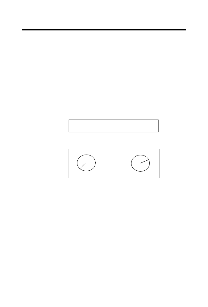
Set the Node Address on the Base Module
Each 1791D base module comes with its internal program set for
node address 63. To reset the node address, adjust the switches
located behind the door on top of the module. The two switches are
most significant digit (MSD) and least significant digit (LSD).
The switches can be set between 00 and 63. Use the node adjusting
tool provided in the package, or a small bladed screwdriver to rotate
the switches.
The rotary switches are read at module power up only. Switch
settings between 64 and 99 cause the module to use the last valid
node address stored internally.
NODE ADDR
(00-63)
Example: Node Address
is set at 62
0
9
1
8
7
6
2
3
4
5
The node address may also be set through RSNetWorx for
DeviceNet™, DeviceNetManager™ or a similar configuration tool.
When software configuration is used for the node address, the
switches must be set between 64 and 99.
LSDMSD
0
1
9
8
7
6
2
3
4
5
41668
Mount the Block(s)
The base and expansion modules mount to a panel or DIN rail,
which must be grounded before installing the module(s).
Publication
1791D-IN003A-EN-P - June 2003
Page 6
6 CompactBlock I/O for DeviceNet Modules Series D
!
WARNING
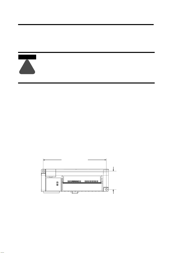
Base Module Mounting
You can install the CompactBlock base module on a panel or DIN
rail.
When used in a Class I, Division 2, hazardous
location, this equipment must be mounted in a
suitable enclosure with proper wiring method
that complies with the governing electrical
codes.
Panel Mounting
1. Place the module against the panel where you want to mount
it.
2. Drill holes in the panel that are aligned with mounting holes
on the module.
3. Place screws through each of the 2 mounting holes and
tighten the screws until the module is firmly in place.
Base Module
141 mm
5.55 in
Publication
41 mm
1.6 in
41673
1791D-IN003A-EN-P - June 2003
Page 7
CompactBlock I/O for DeviceNet Modules Series D 7
ATTENTION
!
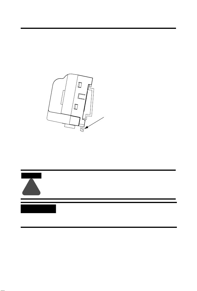
DIN Rail Mounting
1. Hook top of slot over the DIN Rail.
2. Pull down on the locking lever while pressing the block
against the rail.
Locking Lever
90358
3. Push up on the locking lever to secure the block to the rail
when block is flush against the rail.
Connecting an Expansion Module to a Base Module
Expansion blocks should not be installed when
power is applied to the base.
IMPORTANT
NOTE: 1791D-4B0 cannot be connected to expansion modules.
1. Remove the expansion covers from both the base and
expansion modules.
Make sure you carefully read the section
“Communicate With the 1791D Module” on page
15 to change produce and consume data sizes.
Publication
1791D-IN003A-EN-P - June 2003
Page 8
8 CompactBlock I/O for DeviceNet Modules Series D
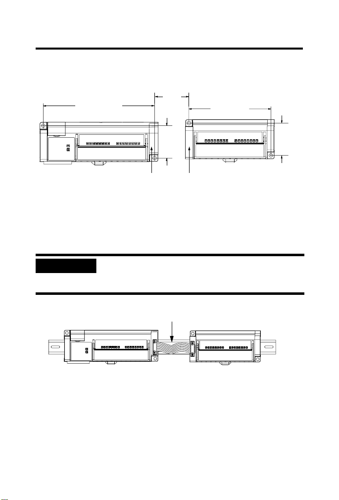
2. Position the expansion block with the proper spacing. See the
illustration below
Base Module Expansion Module
141 mm
5.55 in
.
25 mm
1 in
104 mm
4.09 in
41 mm
1.6 in
Expansion
3. Mount expansion module using panel or DIN rail mounting, as
described in the previous section.
4. Plug the expansion cable into both the base and expansion
modules.
IMPORTANT
The expansion cable can only be connected to the
modules such that the red stripe on the cable is on
top as shown below.
Red strip must be on top of ribbon
5. Replace the expansion covers on both modules.
41 mm
1.6 in
30358
30360
Publication
1791D-IN003A-EN-P - June 2003
Page 9
CompactBlock I/O for DeviceNet Modules Series D 9
!
WARNING
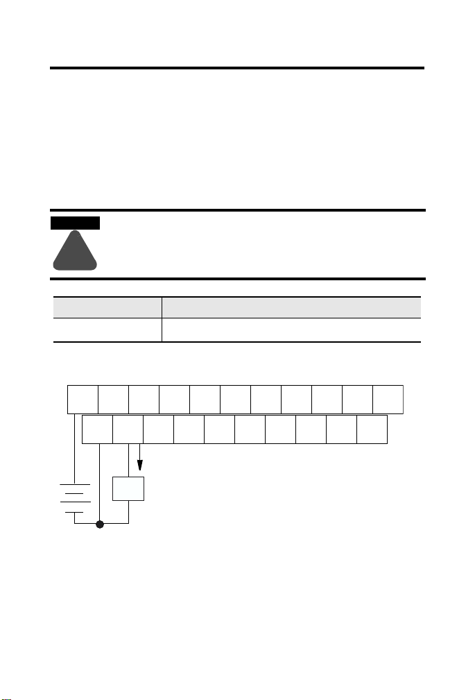
Connect the Input/Output Wires to the Block
Two sets of VDC+ and GND power pins are located on each terminal
(one for each bank of 8 points) except on the 1791D-4B0, -4B4P, and
-0B8P modules. The following figures show the wiring information
for both sinking and sourcing wiring. Refer to the following table for
the proper cable to use for your application.
Use supply wires suitable for 30°C above
surrounding ambient.
Use Cable type
Input and output wiring
Output Wiring Diagram for 1791D-0B16P and 1791D-0B16PX Modules
OUT 0 OUT 2
V
DC
Up to 14AWG (2mm2) stranded (Cu) with 3/64 inch insulation
OUT 4
OUT 8OUT 6
OUT 10
V
DC
OUT 12 OUT 14
Not
Used
GND
OUT 1 OUT 3
OUT 5 OUT 7
GND
OUT 9
OUT 11 OUT 15OUT 13
+
Load
-
Publication
1791D-IN003A-EN-P - June 2003
41669
Page 10

10 CompactBlock I/O for DeviceNet Modules Series D
Output Wiring Diagram for 1791D-0V16P and 1791D-0V16PX Modules
V
DC
OUT 0 OUT 2
GND
-
OUT 1 OUT 3
Load
OUT 4
OUT 5 OUT 7
OUT 8OUT 6
OUT 10
V
DC
GND
OUT 9
OUT 12 OUT 14
OUT 11 OUT 15OUT 13
Not
Used
+
Input Wiring Diagram for 1791D-16V0 and 1791D-16V0X Modules
V
DC
GND
IN 0 IN 2
IN 1 IN 3
IN 4
IN 5 IN 7
IN 8IN 6
IN 10
V
DC
IN 9
GND
IN 12 IN 14
IN 11 IN 15IN 13
+
-
Input Wiring Diagram for 1791D-16B0 and 1791D-16B0X Modules
V
DC
IN 0 IN 2
GND
IN 1 IN 3
IN 4
IN 5 IN 7
V
IN 8IN 6
IN 10
DC
IN 9
IN 12 IN 14
IN 11 IN 15IN 13GND
-
+
Not
Used
41670
Not
Used
41726
41671
Publication
1791D-IN003A-EN-P - June 2003
Page 11

CompactBlock I/O for DeviceNet Modules Series D 11
Wiring Diagram for the 1791D-8B8P Module
V
DC
GND
IN 0 IN 2
IN 1 IN 3
IN 4
IN 5 IN 7
OUT 0IN 6
V
DC
OUT 1
GND
OUT 2
OUT 3 OUT 7OUT 5
OUT 4 OUT 6
Not
Used
-
+
+
Load
-
Wiring Diagram for the 1791D-4B0 Module
V
DC
IN 0 GND IN 2GND
GND
+
-
IN 1
Not
V
DC
Used
V
DC
+
-
Not
Used
Not
Not
Used
Used
Typical PNP 3-wire sensor
Wiring Diagram for the 1791D-4B4P Module
V
DC
IN 0 V
IN 1 V
GND
+
IN 2
DC
IN 3 V
DC
V
DC
DC
GND
DC
+
41672
GND
IN 3 GND
Not
V
DC
OUT 0V
GND
OUT 1
Load
V
Used
OUT 2 GND
GND GNDOUT 3
Not
Used
Not
DC
Used
42343
Not
Used
-
-
Publication
42344
1791D-IN003A-EN-P - June 2003
Page 12

12 CompactBlock I/O for DeviceNet Modules Series D
!
WARNING
Wiring Diagram for the 1791D-0B8P Module
V
DC
GND
OUT 0 OUT 4GND
OUT 2
V
DC
GND
OUT 6 GND
Not
Used
OUT 1 GND
GND GND
+
OUT 3 GND
Load
OUT 5
GND GNDOUT 7
42345
-
Wiring Diagram for the 1791D-8V8P Module
V
DC
IN 0 IN 2 OUT 0IN 6
IN 1 IN 3
GND GND
IN 4
IN 5 IN 7
+
-
OUT 2
V
DC
OUT 1
-
OUT 4 OUT 6
OUT 3 OUT 7OUT 5
Load
+
Used
42346
Not
Connect the DeviceNet Cable
Refer to the following information when connecting the DeviceNet
wire to the 1791D block I/O.
If you connect or disconnect the
communications cable with power applied to
this module or any device on the network, an
electrical arc can occur. This could cause an
explosion in hazardous location installations.
Publication
1791D-IN003A-EN-P - June 2003
Page 13

CompactBlock I/O for DeviceNet Modules Series D 13
1. Connect the DeviceNet cable (drop line) to the unsealed
DeviceNet terminal connector as shown below.
30361
2. Connect the terminal connector to the Block. Use the side
screws on the terminal connector to fasten it to the Block.
IMPORTANT
DeviceNet cable connections must match the color
bars on the blocks. Refer to the table below.
Pin Number: Wire
Color:
1 black V- power return
2 blue CAN_L data line (CAN Low)
3 clear shield between cable jacket and wire
4 white CAN_H data line (CAN High)
5 red V+ positive voltage (hot)
Abbreviation: Description:
Publication
1791D-IN003A-EN-P - June 2003
Page 14

14 CompactBlock I/O for DeviceNet Modules Series D
!
WARNING
Remove the Terminal Block
Follow the directions below to remove the CompactBlock terminal
block.
When you connect or disconnect the Removable
Terminal Block (RTB) with field side power
applied, an electrical arc can occur. This could
cause an explosion in hazardous location
installations.
1. Unscrew the two retaining screws on the side of the terminal
block.
2. Lift the terminal block out of the base.
Retaining Screw
VDC
IN0
IN2
Retaining Screw
IN4
IN1
GND
IN6
IN3
IN5
VDC
IN8
IN7
IN10
IN12
GND
IN9
IN14
IN11
Not
IN13
Used
IN15
Publication
42979
1791D-IN003A-EN-P - June 2003
Page 15

CompactBlock I/O for DeviceNet Modules Series D 15
Insert the Terminal Block
To insert the CompactBlock terminal block.
1. Insert the terminal block by aligning it and pushing it back
until it rests against the back of the module.
2. Tighten the screws on each side of the terminal block until the
terminal block is firmly in place.
Communicate With the 1791D Module
Determine the Baud Rate for Your DeviceNet Connection
All 1791D CompactBlock I/O for DeviceNet modules contain the
autobaud feature. Autobaud lets the modules automatically detect the
baud rate for the network upon connection to the live network.
The 1791D base modules’ I/O is exchanged with the master through
a polled, cyclic or change of state connection.
Polled - master initiates communication by sending its polled I/O
message to the 1791D module. The module consumes the message,
updates any outputs, and produces a response. If inputs are present,
the response contains the input data.
Cyclic - allows configuration of the block as an I/O client. The block
will produce and consume its I/O cyclically at the rate configured.
Change of state - production occurs when an input changes. If no
input change occurs within the expected packet time, a heartbeat
production occurs. This heartbeat production tells the scanner
module that the 1791D I/O module is alive and ready to
communicate. Consumption occurs when data changes and the
master produces new output data to the I/O block.
Publication
1791D-IN003A-EN-P - June 2003
Page 16

16 CompactBlock I/O for DeviceNet Modules Series D
The module produces 1 byte for every 8 inputs. Similarly, the module
consumes 1 byte for every 8 outputs. When an expansion module is
connected, an additional byte will be returned indicating the health of
the expansion module.
IMPORTANT
When installing an expansion module, refer to the
table below to see how many bytes are produced
and consumed by the modules.
Remember, though, when configuring your CompactBlock I/O
application, these values are entered as bytes received (R
transmitted (T
) by the scanner.
x
) and bytes
x
For example, a Base input module produces 2 bytes and consumes 0
bytes. In such a case, the scanner connected to the Base Input
module will receive (R
) 2 bytes and transmit (Tx) 0 bytes.
x
Word/Bit Definitions
The following table lists the combination of input and output
modules and the input and output bytes produced and consumed.
Digital Expander
Base Expansion I/O Points Produced
(input bytes)
16 input 16 in 2 0
16 output 16 out 0 2
8 in / 8 out 8 in / 8 out 1 1
4 in 4 in 1 0
4 in / 4 out 4 in / 4 out 1 1
8 out 8 out 0 1
16 input 16 input 32 input 5 0
16 input 16 output 16 in / 16 out 3 2
16 output 16 input 16 in / 16 out 3 2
Consumed
(output bytes)
Publication
1791D-IN003A-EN-P - June 2003
Page 17

CompactBlock I/O for DeviceNet Modules Series D 17
Digital Expander
Base Expansion I/O Points Produced
16 output 16 output 32 out 1 4
8 in / 8 out 16 input 24 in /8 out 4 1
Digital Expander
Base Expansion I/O Points Produced
8 in / 8 out 16 output 8 in / 24 out 2 3
4 in / 4 out 16 input 20 in / 4 out 3 1
4 in / 4 out 16 output 4 in / 20 out 1 3
8 out 16 input 16 in / 8 out 3 1
8 out 16 output 24 out 1 3
Analog Expander
Base Expansion I/O Points Produced
16 input analog 16 input digital
16 output analog 16 output digital
8 in / 8 out analog 8 in / 8 out digital
4 in / 4 out analog 4 in / 4 out digital
4 in / 2 out analog
4 in / 2 out analog
4 in / 2 out analog
4 in / 2 out analog
(input bytes)
(input bytes)
(input bytes)
14 4
12 6
12 6
12 6
Consumed
(output bytes)
Consumed
(output bytes)
Consumed
(output bytes)
The table below is an example of the word/bit definitions for an
8 in/8 out combination module.
Bit 07 06 05 04 03 02 01 00
Produces I7 I6 I5 I4 I3 I2 I1 I0
Consumes O7 O6 O5 O4 O3 O2 O1 O0
Publication
1791D-IN003A-EN-P - June 2003
Page 18

18 CompactBlock I/O for DeviceNet Modules Series D
The table below is an example of the word/bit definitions for an 8 in/
8 out combination module that uses a 16 input expansion module.
Bit 07 06 05 04 03 02 01 00
Produces 0 I7 I6 I5 I4 I3 I2 I1 I0
Produces 1 I15 I14 I13 I12 I11 I10 I9 I8
Produces 2 I23 I22 I21 I20 I19 I18 I17 I16
Produces 3 ES Reserved
Consumes 0 O7 O6 O5 O4 O3 O2 O1 O0
ES = Expansion Status
The table below describes input and output bits used in both of the
example tables above.
Byte Bit Description
Produces 0-2 O0-O7 Input Status bits - when the bit is set (1), the input is on. Bit 00
Produces 3 O7 If Expansion Status (ES) bit is set, the expansion module is not
Consumes 0 00-07 Output bits - when the bit is set (1), the output will be turned on.
corresponds to input I0, bit 01 corresponds to input I1, bit 02
corresponds to input I2, and so forth.
functioning properly or missing.
Bit 00 corresponds to output O0, bit 01 corresponds to output
O1, bit 02 to output O2, and so forth.
The DeviceNet Network uses advanced network technology,
producer/consumer communication, to increase network
functionality and throughput. Visit our web site at
http://www.ab.com/networks for producer/consumer technology
information and updates.
Publication
1791D-IN003A-EN-P - June 2003
Page 19

CompactBlock I/O for DeviceNet Modules Series D 19
Troubleshoot with the Indicators
The 1791D I/O module has the following indicators:
• Mod/Net status indicator - base only
• Logic status indicator - base only
• I/O status indicators - base and expansion
Mod/Net Status Indicator
Indication: Status:
Off No power or auto bauding
Flashing Green/Off On line but not connected
Solid Green On line, link OK, connected
Flashing Red Recoverable fault - (expansion module fault or module configuration
Mod/Net Status Indicator (continued)
Indication: Status:
Solid Red Unrecoverable fault
Green to Red to Off At powerup only - LED test
error)
I/O connection fault - one or more I/O connections in the timed-out state
Communication failure - duplicate node address present or incorrect
baud rate
Logic Status Indicator
Indication: Status:
Off Logic is disabled
Solid Green Logic is enabled
Flashing Green Local forces are applied and local logic is enabled
Publication
1791D-IN003A-EN-P - June 2003
Page 20

20 CompactBlock I/O for DeviceNet Modules Series D
I/O Status Indicators
Function: LED Color: Module Illumination: Condition:
Outputs Each output:
Yellow
Inputs Each Input:
Yellow
None
Yello w
None
Yello w
Output not energized
Output energized
No valid input
Valid input
Specifications
Sinking or Sourcing Input Specifications
Inputs per block groups of 4 or 8
Off-state Voltage 5V dc maximum
On-state Voltage 30V dc @ 40°C maximum
Off-state Current 1.5mA minimum
On-state Current 11mA @ 30V dc maximum
Outputs per block groups of 4 or 8
On-state Voltage Range 10 - 30V dc
On-state Voltage Drop 0.5V dc @ rated current
On-state Current 0.5A maximum
Off-state Leakage 1.0mA maximum
Module Current (per output) 0.5A maximum
Surge Current - for 10 mS
repeatable every 2 S
Indicators Mod/Net status - red/green
25V dc @ 60°C maximum
10V dc minimum
2mA @ 10V dc minimum
1.0A maximum
Logic status - red/green
I/O status - yellow
Publication
1791D-IN003A-EN-P - June 2003
Page 21

CompactBlock I/O for DeviceNet Modules Series D 21
General Specifications
Communication Rate
Thick Cable
Flat Media
Isolation
Auxiliary I/O power to DeviceNet
I/O group-to-group
I/O group-to-DeviceNet
DeviceNet Power
Voltage
Current
Expansion Power
Voltage
Current
Auxiliary Power Inputs
Voltage
Current
Auxiliary Power Outputs
Voltage
Current
Base Module Dimensions 150mm X 50mm X 38mm
Expansion Module Dimensions 115mm X 50mm X 38mm
Field Wiring Tightening Torque 5-7lb-in. (0.5-0.6 Nm)
Operating Temperature
Storage Temperature IEC 60068-2-1 (Test Ab, Un-packaged Non-operating Cold),
125Kbps @ 500m (1600ft)
250Kbps @ 200m (600ft)
500Kbps @ 100m (330ft)
125Kbps @ 420m (1230ft)
250Kbps @ 200m (490ft)
500Kbps @ 75m (245ft)
500V ac/60s
500V ac/60s
500V ac/60s
11 - 25V dc
200mA maximum (with expansion)
(for the 1791D-4B0, 150mA)
5V dc
100mA
10-30V dc
88mA each group of 8
10-30V dc
4A each group of 8
5.91in X 1.97in X 1.5in
4.4in X 1.97in X 1.5in
IEC 60068-2-1 (Test Ad, Operating Cold),
IEC 60068-2-2 (Test Bd, Operating Dry Heat),
IEC 60068-2-14 (Test Nb, Operating Thermal Shock):
0 to 60°C (32 to 140°F)
IEC 60068-2-2 (Test Bb, Un-packaged Non-operating Dry Heat),
IEC 60068-2-14 (Test Na, Un-packaged Non-operating Thermal
Shock):
-40 to 85°C (-40 to 185°F)
Publication
1791D-IN003A-EN-P - June 2003
Page 22

22 CompactBlock I/O for DeviceNet Modules Series D
General Specifications
Relative Humidity IEC 60068-2-30 (Test Db, Un-packaged Non-operating
Shock IEC60068-2-27 (Test Ea, Unpackaged shock):
Emissions CISPR 11:
Vibration IEC60068-2-6 (Test Fc, Operating):
Conductors Wire Size
Category
ESD Immunity IEC 61000-4-2:
Radiated RF Immunity IEC 61000-4-3:
EFT/B Immunity IEC 61000-4-4:
Surge Transient Immunity IEC 61000-4-5:
Conducted RF Immunity IEC 61000-4-6:
Damp Heat):
5-95% non-condensing
Operating 30g
Non-operating 50g
Group 1, Class A
5g @ 10-500Hz
14 gauge (2mm2) stranded maximum
3/64 inch insulation maximum
1, 2
2
6kV contact discharges
8kV air discharges
10V/m with 1kHz sine-wave 80%AM from 80MHz to 1000MHz
10V/m with 200Hz 50% Pulse 100%AM at 900Mhz
±2kV at 5kHz on signal ports
±2kV at 5kHz on communications ports
±1kV line-line(DM) and ±2kV line-earth(CM) on signal ports
+2kV line-earth (CM) on shielded ports
10Vrms with 1kHz sine-wave 80%AM from 150kHz to 80MHz
Publication
1791D-IN003A-EN-P - June 2003
Page 23

CompactBlock I/O for DeviceNet Modules Series D 23
General Specifications (continued)
Certifications:
(when product is marked)
Enclosure Type Rating Meets IP20
1 You use this conductor category information for planning conductor routing as described in the system
level installation manual.
2 See publication 1770-4.1, “Programmable Controller Wiring and Grounding Guidelines.”
3 See the Product Certification link at www.ab.com for Declarations of Conformity, Certificates, and other
certification details.
UL UL Listed Industrial Control Equipment
UL UL Listed for Class I, Division 2 Group A, B, C, D
Hazardous Locations
c-UL-us UL Listed Industrial Control Equipment, certified for US
and Canada
c-UL-us UL Listed for Class I, Division 2 Group A,B,C,D Hazardous
Locations, certified for U.S. and Canada
CE3European Union 89/336/EEC EMC Directive, compliant
with:
EN 61000-6-4; Industrial Emissions
EN 50082-2; Industrial Immunity
EN 61326; Meas./Control/Lab., Industrial Requirements
EN 61000-6-2; Industrial Immunity
C-Tick3Australian Radiocommunications Act, compliant with:
AS/NZS CISPR 11; Industrial Emissions
ODVA ODVA conformance tested to DeviceNet specifications
IMPORTANT
Input and output wiring must be in accordance
with Class I, Division 2 wiring methods and in
accordance with the authority having jurisdiction.
Publication
1791D-IN003A-EN-P - June 2003
Page 24

24 CompactBlock I/O for DeviceNet Modules Series D
North American Hazardous Location Approval
The following information applies when
operating this equipment in hazardous locations:
Products marked “CL I, DIV 2, GP A, B, C, D” are suitable
for use in Class I Division 2 Gro ups A, B, C, D,
Hazardous Locations an d nonhazardous locations only.
Each product is supplied with m arkings on the rating
nameplate indicating the hazardous location
temperature code. When co mbining products within a
system, the most a dverse temperature code (lowest “T”
number) may be used to help deter mine the overall
temperature code of the syst em. Combinations of
equipment in your system ar e subject to investigation
by the local Authority Having Jurisdi ction at the time of
installation.
WARNING
!
EXPLOSION HAZARD
• Do not disconnect
equipment unless
power has been
removed or the area is
known to be
nonhazardous.
• Do not disconnect
connections to this
equipment unless
power has been
removed or the area is
known to be
nonhazardous. Secure
any external
connections that mate
to this equipment by
using screws, sliding
latches, threaded
connectors, or other
means provided with
this product.
• Substitution of
components may
impair suitability for
Class I, Division 2.
• If this product contains
batteries, they must
only be changed in an
area known to be
nonhazardous.
Informations sur l’utilisation de cet équipement en
environnements dangereux :
Les produits marqués "CL I, DIV 2, GP A , B, C, D" ne
conviennent qu’à une utilisation en env ironnements de Classe
I Division 2 Groupes A, B, C, D danger eux et non dangereux.
Chaque produit est livré avec d es marquages sur sa plaque
d’identification qui indiquent le c ode de température pour les
environnements dangereux. Lor sque plusieurs produits so nt
combinés dans un système , le code de température le plus
défavorable (code de température le plus faible) peut être
utilisé pour déterminer le code de températu re global du
système. Les combinaison s d’équipements dans le système
sont sujettes à inspection p ar les autorités locales qualifiées
au moment de l’installation.
AVERTISSEMENT
!
RISQUE D’EXPLOSION
• Couper le courant ou
s’assurer que
l’environnement est
classé non dangereux
avant de débrancher
l'équipement.
• Couper le courant ou
s'assurer que
l’environnement est
classé non dangereux
avant de débrancher
les connecteurs. Fixer
tous les connecteurs
externes reliés à cet
équipement à l'aide de
vis, loquets
coulissants,
connecteurs filetés ou
autres moyens fourn is
avec ce produit.
• La substitution de
composants peut
rendre cet équipement
inadapté à une
utilisation en
environnement de
Classe I, Division 2.
• S’assurer que
l’environnement est
classé non dangereux
avant de changer les
piles.
Publication
1791D-IN003A-EN-P - June 2003
Page 25

CompactBlock I/O for DeviceNet Modules Series D 25
This product has been tested at an Open DeviceNet Vendor
Association, Inc. (ODVA) authorized independent test laboratory and
found to comply with ODVA Conformance Test. Please contact the
ODVA website (http://www.odva.org) for listing of products tested by
ODVA independent test labs for further details.
Publication
1791D-IN003A-EN-P - June 2003
Page 26

26 CompactBlock I/O for DeviceNet Modules Series D
Notes:
Publication
1791D-IN003A-EN-P - June 2003
Page 27

CompactBlock I/O for DeviceNet Modules Series D 27
CompactBlock and DeviceNetManager are trademarks of Rockwell Automation, Inc.
DeviceNet is a trademark of Open DeviceNet Vendor Association.
RSNetWorx for DeviceNet is a trademark of Rockwell Software, Inc.
Publication
1791D-IN003A-EN-P - June 2003
Page 28

Rockwell Automation Support
Rockwell Automation provides technical information on the web to assist you
in using our products. At http://support.rockwellautomation.com, you can
find technical manuals, a knowledge base of FAQs, technical and application
notes, sample code and links to software service packs, and a MySupport
feature that you can customize to make the best use of these tools.
For an additional level of technical phone support for installation,
configuration and troubleshooting, we offer TechConnect Support programs.
For more information, contact your local distributor or Rockwell Automation
representative, or visit http://support.rockwellautomation.com.
Installation Assistance
If you experience a problem with a hardware module within the first 24 hours
of installation, please review the information that’s contained in this manual.
You can also contact a special Customer Support number for initial help in
getting your module up and running:
United States 1.440.646.3223 Monday – Friday, 8am – 5pm EST
Outside United States Please contact your local Rockwell Automation representative for any
New Product Satisfaction Return
Rockwell tests all of our products to ensure that they are fully operational
when shipped from the manufacturing facility. However, if your product is not
functioning and needs to be returned:
United States Contact your distributor. You must provide a Customer Support case number
Outside United States Please contact your local Rockwell Automation representative for return
technical support issues.
(see phone number above to obtain one) to your distributor in order to
complete the return process.
procedure.
Publication 1791D-IN003A-EN-P - June 2003 PN 957726-28
Copyright © 2003 Rockwell Automation , Inc. All rights reserved . Printed in the U.S.A.
 Loading...