

Page 1

User Manual
Guard I/O DeviceNet Safety Modules
Catalog Numbers 1732DS-IB8, 1732DS-IB8XOBV4, 1791DS-IB12, 1791DS-IB8XOB8, 1791DS-IB4XOW4, 1791DS-IB8XOBV4,
1791DS-IB16
Page 2
Important User Information
IMPORTANT
Solid-state equipment has operational characteristics differing from those of electromechanical equipment. Safety
Guidelines for the Application, Installation and Maintenance of Solid State Controls (publication SGI-1.1
your local Rockwell Automation sales office or online at http://www.rockwellautomation.com/literature/
important differences between solid-state equipment and hard-wired electromechanical devices. Because of this difference,
and also because of the wide variety of uses for solid-state equipment, all persons responsible for applying this equipment
must satisfy themselves that each intended application of this equipment is acceptable.
In no event will Rockwell Automation, Inc. be responsible or liable for indirect or consequential damages resulting from the
use or application of this equipment.
The examples and diagrams in this manual are included solely for illustrative purposes. Because of the many variables and
requirements associated with any particular installation, Rockwell Automation, Inc. cannot assume responsibility or
liability for actual use based on the examples and diagrams.
No patent liability is assumed by Rockwell Automation, Inc. with respect to use of information, circuits, equipment, or
software described in this manual.
Reproduction of the contents of this manual, in whole or in part, without written permission of Rockwell Automation,
Inc., is prohibited.
Throughout this manual, when necessary, we use notes to make you aware of safety considerations.
available from
) describes some
WARNING: Identifies information about practices or circumstances that can cause an explosion in a hazardous environment,
which may lead to personal injury or death, property damage, or economic loss.
ATTENTION: Identifies information about practices or circumstances that can lead to personal injury or death, property
damage, or economic loss. Attentions help you identify a hazard, avoid a hazard, and recognize the consequence.
SHOCK HAZARD: Labels may be on or inside the equipment, for example, a drive or motor, to alert people that dangerous
voltage may be present.
BURN HAZARD: Labels may be on or inside the equipment, for example, a drive or motor, to alert people that surfaces may
reach dangerous temperatures.
Identifies information that is critical for successful application and understanding of the product.
Allen-Bradley, Rockwell Software, Rockwell Automation, GuardLogix, SmartGuard, RSNetWorx, RSLogix, Logix 5000, Studio 5000, Guard I/O, CompactBlock, and TechConnect are trademarks of Rockwell Automation,
Inc.
Trademarks not belonging to Rockwell Automation are property of their respective companies.
Page 3

Summary of Changes
This manual contains new and updated information. Changes throughout this
revision are marked by change bars, as shown to the right of this paragraph.
New and Updated
Information
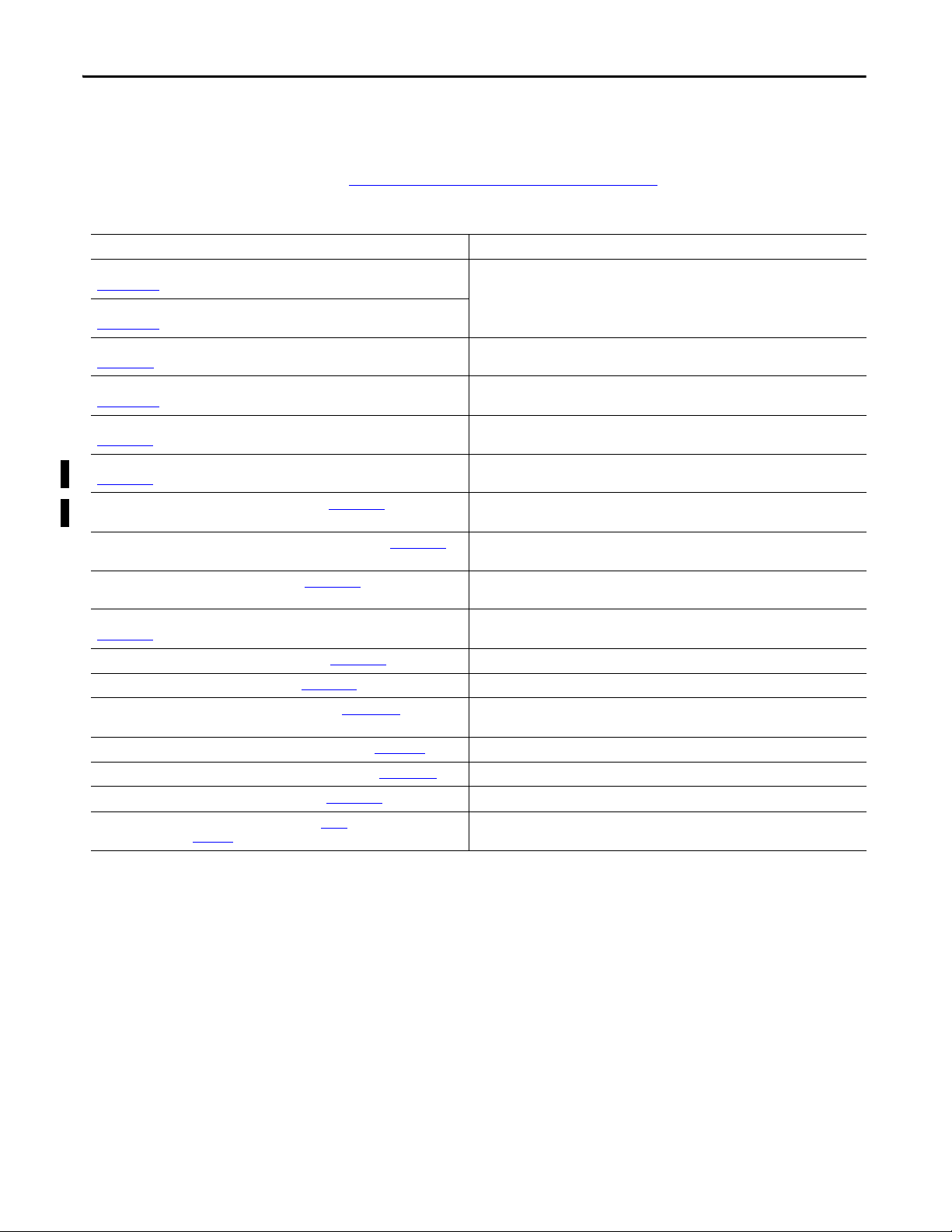
This table contains the changes made to this revision.
Top ic Pag e
Studio 5000 Environment 9
Additional Resources 10
Programming Requirements 19
Safety Data 161
Rockwell Automation Publication 1791DS-UM001J-EN-P - May 2013 3
Page 4

Summary of Changes
Notes:
4 Rockwell Automation Publication 1791DS-UM001J-EN-P - May 2013
Page 5

Table of Contents
Preface
About the Modules
Understand the Operation of Safety
Functions
About the Specifications and Dimensions in This Manual . . . . . . . . . . . . . 9
Studio 5000 Environment . . . . . . . . . . . . . . . . . . . . . . . . . . . . . . . . . . . . . . . . . . 9
Additional Resources . . . . . . . . . . . . . . . . . . . . . . . . . . . . . . . . . . . . . . . . . . . . . 10
Terminology. . . . . . . . . . . . . . . . . . . . . . . . . . . . . . . . . . . . . . . . . . . . . . . . . . . . . 11
Chapter 1
Before You Begin . . . . . . . . . . . . . . . . . . . . . . . . . . . . . . . . . . . . . . . . . . . . . . . . 13
Understand Suitability for Use . . . . . . . . . . . . . . . . . . . . . . . . . . . . . . . . . . . . 14
Follow Precautions for Use . . . . . . . . . . . . . . . . . . . . . . . . . . . . . . . . . . . . . . . 14
Precautions to Mount, Wire, and Clean. . . . . . . . . . . . . . . . . . . . . . . . . . . . 17
I/O Module Overview. . . . . . . . . . . . . . . . . . . . . . . . . . . . . . . . . . . . . . . . . . . . 17
Programming Requirements . . . . . . . . . . . . . . . . . . . . . . . . . . . . . . . . . . . . . . 19
Guard I/O Catalog Numbers . . . . . . . . . . . . . . . . . . . . . . . . . . . . . . . . . . . . . 19
About CIP Safety in DeviceNet Safety Architectures. . . . . . . . . . . . . . . . 19
Identify Major Parts of the Modules . . . . . . . . . . . . . . . . . . . . . . . . . . . . . . . 21
Chapter 2
Safety I/O Modules . . . . . . . . . . . . . . . . . . . . . . . . . . . . . . . . . . . . . . . . . . . . . . 25
Self-diagnostic Functions . . . . . . . . . . . . . . . . . . . . . . . . . . . . . . . . . . . . . . . . . 26
Configuration Lock . . . . . . . . . . . . . . . . . . . . . . . . . . . . . . . . . . . . . . . . . . . . . . 26
I/O Status Data. . . . . . . . . . . . . . . . . . . . . . . . . . . . . . . . . . . . . . . . . . . . . . . . . . 26
Safety Inputs. . . . . . . . . . . . . . . . . . . . . . . . . . . . . . . . . . . . . . . . . . . . . . . . . . . . . 26
Using a Test Output with a Safety Input . . . . . . . . . . . . . . . . . . . . . . . 27
Single Channel Mode. . . . . . . . . . . . . . . . . . . . . . . . . . . . . . . . . . . . . . . . . 29
Dual-channel Mode and Discrepancy Time. . . . . . . . . . . . . . . . . . . . . 30
Dual-channels, Equivalent . . . . . . . . . . . . . . . . . . . . . . . . . . . . . . . . . . . . 30
Dual-channels, Complementary . . . . . . . . . . . . . . . . . . . . . . . . . . . . . . . 31
Safety Input Fault Recovery . . . . . . . . . . . . . . . . . . . . . . . . . . . . . . . . . . . 33
Input Delays . . . . . . . . . . . . . . . . . . . . . . . . . . . . . . . . . . . . . . . . . . . . . . . . . 33
Test Outputs Configured as Muting Outputs . . . . . . . . . . . . . . . . . . . . . . 34
Safety Outputs. . . . . . . . . . . . . . . . . . . . . . . . . . . . . . . . . . . . . . . . . . . . . . . . . . . 36
Safety Output with Test Pulse . . . . . . . . . . . . . . . . . . . . . . . . . . . . . . . . . 36
Dual-channel Setting . . . . . . . . . . . . . . . . . . . . . . . . . . . . . . . . . . . . . . . . . 37
Safety Output Fault Recovery . . . . . . . . . . . . . . . . . . . . . . . . . . . . . . . . . 37
Controlling Devices . . . . . . . . . . . . . . . . . . . . . . . . . . . . . . . . . . . . . . . . . . . . . . 38
Safety Precautions. . . . . . . . . . . . . . . . . . . . . . . . . . . . . . . . . . . . . . . . . . . . . . . . 38
Legislation and Standards. . . . . . . . . . . . . . . . . . . . . . . . . . . . . . . . . . . . . . . . . 39
Europe . . . . . . . . . . . . . . . . . . . . . . . . . . . . . . . . . . . . . . . . . . . . . . . . . . . . . . 39
North America. . . . . . . . . . . . . . . . . . . . . . . . . . . . . . . . . . . . . . . . . . . . . . . 40
Japan . . . . . . . . . . . . . . . . . . . . . . . . . . . . . . . . . . . . . . . . . . . . . . . . . . . . . . . . 40
EC Directives. . . . . . . . . . . . . . . . . . . . . . . . . . . . . . . . . . . . . . . . . . . . . . . . . . . . 41
EMC Directive. . . . . . . . . . . . . . . . . . . . . . . . . . . . . . . . . . . . . . . . . . . . . . . 41
Compliance with EC Directives . . . . . . . . . . . . . . . . . . . . . . . . . . . . . . . 41
Rockwell Automation Publication 1791DS-UM001J-EN-P - May 2013 5
Page 6

Table of Contents
Chapter 3
Install and Connect Your Modules
Wiring Examples
Considerations for Module Installation . . . . . . . . . . . . . . . . . . . . . . . . . . . . 43
Install the Module . . . . . . . . . . . . . . . . . . . . . . . . . . . . . . . . . . . . . . . . . . . . . . . . 44
Connect I/O Power and I/O Cables . . . . . . . . . . . . . . . . . . . . . . . . . . . . . . . 45
Connect Communication Connectors . . . . . . . . . . . . . . . . . . . . . . . . . . . . . 46
Set the Node Address . . . . . . . . . . . . . . . . . . . . . . . . . . . . . . . . . . . . . . . . . . . . . 46
Chapter 4
Input Examples . . . . . . . . . . . . . . . . . . . . . . . . . . . . . . . . . . . . . . . . . . . . . . . . . . 47
Emergency Stop Switch Dual-channel Inputs with Manual Reset . 48
Two-hand Monitor . . . . . . . . . . . . . . . . . . . . . . . . . . . . . . . . . . . . . . . . . . . 49
Mode Select Switch . . . . . . . . . . . . . . . . . . . . . . . . . . . . . . . . . . . . . . . . . . . 50
Light Curtain . . . . . . . . . . . . . . . . . . . . . . . . . . . . . . . . . . . . . . . . . . . . . . . . 51
Reset Switch . . . . . . . . . . . . . . . . . . . . . . . . . . . . . . . . . . . . . . . . . . . . . . . . . 52
Source Output Examples. . . . . . . . . . . . . . . . . . . . . . . . . . . . . . . . . . . . . . . . . . 53
Redundant Safety Contactors. . . . . . . . . . . . . . . . . . . . . . . . . . . . . . . . . . 53
Single Channel . . . . . . . . . . . . . . . . . . . . . . . . . . . . . . . . . . . . . . . . . . . . . . . 54
Bipolar Output Examples . . . . . . . . . . . . . . . . . . . . . . . . . . . . . . . . . . . . . . . . . 55
Dual-load Bipolar Outputs . . . . . . . . . . . . . . . . . . . . . . . . . . . . . . . . . . . . 55
Single Channel . . . . . . . . . . . . . . . . . . . . . . . . . . . . . . . . . . . . . . . . . . . . . . . 56
Relay Output Examples . . . . . . . . . . . . . . . . . . . . . . . . . . . . . . . . . . . . . . . . . . . 57
Relay Outputs with Dual-channel Mode and External Device
Monitoring Input. . . . . . . . . . . . . . . . . . . . . . . . . . . . . . . . . . . . . . . . . . . . . 57
Interlock String. . . . . . . . . . . . . . . . . . . . . . . . . . . . . . . . . . . . . . . . . . . . . . . 58
Test Output Examples . . . . . . . . . . . . . . . . . . . . . . . . . . . . . . . . . . . . . . . . . . . . 59
Standard Inputs and Outputs. . . . . . . . . . . . . . . . . . . . . . . . . . . . . . . . . . 59
Muting Lamp Output. . . . . . . . . . . . . . . . . . . . . . . . . . . . . . . . . . . . . . . . . 60
Chapter 5
Configure Modules with the Logix
Designer Application
6 Rockwell Automation Publication 1791DS-UM001J-EN-P - May 2013
Use the Help Button . . . . . . . . . . . . . . . . . . . . . . . . . . . . . . . . . . . . . . . . . . . . . 61
Add Modules to the I/O Configuration Tree . . . . . . . . . . . . . . . . . . . . . . . 62
Set Up the Module Definition. . . . . . . . . . . . . . . . . . . . . . . . . . . . . . . . . . . . . 64
Values and States of Tags . . . . . . . . . . . . . . . . . . . . . . . . . . . . . . . . . . . . . . 70
Configure the Safety Tab. . . . . . . . . . . . . . . . . . . . . . . . . . . . . . . . . . . . . . . . . . 71
Configuration Ownership - Reset Ownership . . . . . . . . . . . . . . . . . . . 73
Configuration Signature . . . . . . . . . . . . . . . . . . . . . . . . . . . . . . . . . . . . . . 73
Configure the Input Configuration Tab. . . . . . . . . . . . . . . . . . . . . . . . . . . . 74
Configure the Test Output Tab . . . . . . . . . . . . . . . . . . . . . . . . . . . . . . . . . . . 76
Configure the Output Configuration Tab . . . . . . . . . . . . . . . . . . . . . . . . . . 77
Save and Download Module Configuration. . . . . . . . . . . . . . . . . . . . . . . . . 79
Page 7

Chapter 6
Table of Contents
Configure Modules in
RSNetWorx for DeviceNet Software
Considerations When Replacing
Guard
I/O Modules
Before You Begin . . . . . . . . . . . . . . . . . . . . . . . . . . . . . . . . . . . . . . . . . . . . . . . . 81
Add Modules to the I/O Configuration. . . . . . . . . . . . . . . . . . . . . . . . . . . . 82
Safety Network Number (SNN). . . . . . . . . . . . . . . . . . . . . . . . . . . . . . . 83
Configuration Signature . . . . . . . . . . . . . . . . . . . . . . . . . . . . . . . . . . . . . . 85
Configure the I/O Module. . . . . . . . . . . . . . . . . . . . . . . . . . . . . . . . . . . . . . . . 86
Configure the Input Channel . . . . . . . . . . . . . . . . . . . . . . . . . . . . . . . . . 86
Configure the Test Output. . . . . . . . . . . . . . . . . . . . . . . . . . . . . . . . . . . . 89
Configure the Output Channel. . . . . . . . . . . . . . . . . . . . . . . . . . . . . . . . 90
Configure Input and Output Error Latch Times . . . . . . . . . . . . . . . . 90
Save and Download the Module Configuration. . . . . . . . . . . . . . . . . . . . . 92
Set Up the 1791DS I/O Module Definition. . . . . . . . . . . . . . . . . . . . . . . . 93
Set the Connection Type . . . . . . . . . . . . . . . . . . . . . . . . . . . . . . . . . . . . . 99
Set the Connection Configuration. . . . . . . . . . . . . . . . . . . . . . . . . . . . 100
Set the Communication Parameters. . . . . . . . . . . . . . . . . . . . . . . . . . . 101
Configuration Ownership—Reset Ownership . . . . . . . . . . . . . . . . . 103
Set the Safety Network Number (SNN) . . . . . . . . . . . . . . . . . . . . . . . 105
Set Your Password. . . . . . . . . . . . . . . . . . . . . . . . . . . . . . . . . . . . . . . . . . . 107
I/O Data Tab . . . . . . . . . . . . . . . . . . . . . . . . . . . . . . . . . . . . . . . . . . . . . . . 108
Troubleshooting . . . . . . . . . . . . . . . . . . . . . . . . . . . . . . . . . . . . . . . . . . . . . . . . 109
Chapter 7
Considerations When Replacing Guard I/O Modules. . . . . . . . . . . . . . 115
Why You Need to Manually Set the SNN . . . . . . . . . . . . . . . . . . . . . 116
GuardLogix Controllers versus SmartGuard Controllers. . . . . . . . 117
Replacing an I/O Module When Using a SmartGuard Controller. . . 117
Replacing an I/O Module When Using a GuardLogix Controller . . . 121
I/O Replacement with ‘Configure Only When No Safety
Signature Exists’ Enabled. . . . . . . . . . . . . . . . . . . . . . . . . . . . . . . . . . . . . 121
I/O Replacement with ‘Configure Always’ Enabled . . . . . . . . . . . . 126
Interpret Status Indicators
Get Point Status from Modules by
Using Explicit Messaging
Chapter 8
Module Indicators . . . . . . . . . . . . . . . . . . . . . . . . . . . . . . . . . . . . . . . . . . . . . . 129
Module Status and Network Status Indicators Combination. . . . . . . . 130
1791DS-IB12, 1791DS-IB8XOB8, and 1791DS-IB4XOW4
Status Indicators . . . . . . . . . . . . . . . . . . . . . . . . . . . . . . . . . . . . . . . . . . . . . . . . 131
1732DS-IB8XOBV4, 1732DS-IB8, 1791DS-IB8XOBV4, and
1791DS-IB16 Status Indicators . . . . . . . . . . . . . . . . . . . . . . . . . . . . . . . . . . 133
Appendix A
Considerations for Obtaining Point Status . . . . . . . . . . . . . . . . . . . . . . . . 137
1791DS-IB8XOB8 Module Definition Configuration . . . . . . . . . . . . . 138
1791DS-IB4XOW4 Module Definition Configuration . . . . . . . . . . . . 142
1791DS-IB12 Module Definition Configuration . . . . . . . . . . . . . . . . . . 145
I/O Assembly and Reference Data . . . . . . . . . . . . . . . . . . . . . . . . . . . . . . . . 148
Rockwell Automation Publication 1791DS-UM001J-EN-P - May 2013 7
Page 8

Table of Contents
Safety Data
Configuration Reference Information
Index
1791DS-IB12, 1791DS-IB8XOB8, 1791DS-IB4XOW4 Data . . 148
1732DS-IB8, 1732DS-IB8XOBV4, 1791DS-IB8XOBV4, and
1791DS-IB16 Data . . . . . . . . . . . . . . . . . . . . . . . . . . . . . . . . . . . . . . . . . . 152
Explicit Messages . . . . . . . . . . . . . . . . . . . . . . . . . . . . . . . . . . . . . . . . . . . . . . . . 155
Basic Format of Explicit Messages. . . . . . . . . . . . . . . . . . . . . . . . . . . . . . . . . 157
Explicit Messages . . . . . . . . . . . . . . . . . . . . . . . . . . . . . . . . . . . . . . . . . . . . . . . . 158
Appendix B
. . . . . . . . . . . . . . . . . . . . . . . . . . . . . . . . . . . . . . . . . . . . . . . . . . . . . . . . . . . . . . . . 161
Appendix C
Understanding Parameter Groups . . . . . . . . . . . . . . . . . . . . . . . . . . . . . . . . 165
Allocate Remote I/O . . . . . . . . . . . . . . . . . . . . . . . . . . . . . . . . . . . . . . . . . . . . 167
I/O Data Supported by Each Module . . . . . . . . . . . . . . . . . . . . . . . . . . . . . 167
8 Rockwell Automation Publication 1791DS-UM001J-EN-P - May 2013
Page 9
Preface
Read and understand this manual before using the described products. Consult
your Rockwell Automation representative if you have any questions or
comments. This manual describes how to use the Guard I/O modules.
This manual is intended for users of ArmorBlock and CompactBlock Guard I/O
modules. Hereafter, in this manual we refer to the modules as Guard I/O
modules.
About the Specifications and
Dimensions in This Manual
Studio 5000 Environment
Product specifications and accessories can change at any time based on
improvements and other reasons. Consult with your Rockwell Automation
representative to confirm actual specifications of purchased product. Dimensions
and weights are nominal and are not for use for manufacturing purposes, even
when tolerances are shown.
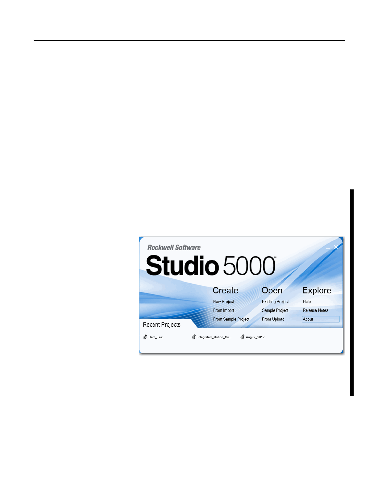
The Studio 5000™ Engineering and Design Environment combines engineering
and design elements into a common environment. The first element in the Studio
5000 environment is the Logix Designer application. The Logix Designer
application is the rebranding of RSLogix™ 5000 software and will continue to be
the product to program Logix5000™ controllers for discrete, process, batch,
motion, safety, and drive-based solutions.
The Studio 5000 environment is the foundation for the future of Rockwell
Automation® engineering design tools and capabilities. This environment is the
one place for design engineers to develop all of the elements of their control
system.
Rockwell Automation Publication 1791DS-UM001J-EN-P - May 2013 9
Page 10
Preface
Additional Resources
Refer to the following as needed for additional help when setting up and using
your modules. For specifications refer to the relevant installation instructions.
You can view or download publications at
http://www.rockwellautomation.com/literature
. To order paper copies of
technical documentation, contact your local Allen-Bradley distributor or
Rockwell Automation sales representative.
Resource Description
ArmorBlock Guard I/O DeviceNet Module Installation Instructions, publication
1732DS-IN001
CompactBlock Guard I/O DeviceNet Module Installation Instructions, publication
1791DS-IN002
DeviceNet Modules in Logix5000 Control Systems User Manual, publication
DNET-UM004
DeviceNet Safety I/O Modules Series 1791DS Installation Instructions, publication
1791DS-IN001
DeviceNet Safety Scanner for GuardPLC Controllers User Manual, publication
1753-UM002
GuardLogix 5570 Controller Systems Safety Reference Manual, publication
1756-RM099
GuardLogix 5570 Controllers User Manual, publication 1756-UM022 Provides information on how to install, configure, program, and use GuardLogix 5570
GuardLogix Controller Systems Safety Reference Manual, publication 1756-RM093 Provides information on safety application requirements for GuardLogix 5560 and 5570
GuardLogix Controllers User Manual, publication 1756-UM020
GuardLogix Safety Application Instructions Safety Reference Manual, publication
1756-RM095
GuardPLC Controller Systems User Manual, publication 1753-UM001 Describes in brief the safety concept of the GuardPLC family of controllers.
GuardPLC Safety Reference Manual, publication 1753-RM002
ODVA Media Planning and Installation Guide, publication 00148-BR001 Describes the required media components and how to plan for and install these required
SmartGuard 600 Controllers Installation Instructions, publication 1752-IN001 Provides information related to installation of SmartGuard 600 controllers.
SmartGuard 600 Controllers Safety Reference Manual, publication 1752-RM001
SmartGuard 600 Controllers User Manual, publication 1752-UM001 Describes how to configure, operate, and troubleshoot the controller.
ODVA Planning and Installation Manual, publication 00027
EtherNet/IP Library at ODVA.org
, available from the
Provides detailed specifications and information related to installation of Guard I/O
modules.
Provides information on how to connect the controller to the network.
Provides detailed specifications and information related to installation of these Guard I/O
modules: 1791DS-IB12, 1791DS-IB8XOB8, and 1791DS-IB4XOW4.
Provides information on installing, operating, and maintaining the scanner.
Provides information on safety applic ation requirements for GuardLogix 5570 controllers in
Studio 5000 Logix Designer projects.
controllers in Studio 5000™ Logix Designer projects.
controllers in RSLogix 5000 projects.
Provides information on how to install, configure, program, and use GuardLogix 5560 and
5570 controllers in RSLogix 5000 projects.
Provides reference information describing the GuardLogix Safety Application Instruction
Set.
Explains how the GuardPLC control system can be used in safety applications.
components.
Describes SmartGuard 600-specific safety requirements and controller features.
Describes the required media components and how to plan for and install these required
components.
10 Rockwell Automation Publication 1791DS-UM001J-EN-P - May 2013
Page 11

Preface
Terminology
Ter m M ea nin g
Bus off Indicates a status of very high error-count occurrence on a communication cable. A bus off error is detected when the internal error counter counts more
errors than the predetermined threshold value. (The error counter returns to zero when the master is started or restarted.)
Connection Logical communication channel for communication between nodes. Connections are maintained and controlled between masters and slaves.
CRTL Connection reaction time limit.
DeviceNet safety An implementation of a safety protocol on a standard DeviceNet network.
EDS Acronym for electronic data sheet, a template that RSNetWorx for DeviceNet software uses to display the configuration parameters, I/O data profile, and
connection-type support for a given DeviceNet safety module. These are text files used by RSNetWorx for DeviceNet software to identify products and
commission them on a network.
L- Output +24V DC common.
M Sinking output common channel, output switches to the common voltage.
MTBF Acronym for mean time between failure, the average time between failure occurrences.
ODVA Acronym for Open DeviceNet Vendor Association, a nonprofit association of vendors established for the promotion of DeviceNet networks.
P Sourcing output channel, output switches to the plus voltage.
PFD Acronym for probability of failure on demand, the average probability of a system to fail to perform its design function on demand.
PFH Acronym for probability of failure per hour, the probability of a system to have a dangerous failure occur per hour.
Proof test Periodic test performed to detect failures in a safety-related system so that, if necessary, the system can be restored to an as-new condition or as close as
practical to this condition.
S+ Output +24V DC.
SNN Acronym for safety network number, which uniquely identifies a network across all networks in the safety system. You are responsible for assigning a
unique number for each safety network or safety sub-net within a system.
Standard Devices or portions of devices that do not participate in the safety function.
Refer to the table for the meaning of common terms.
Rockwell Automation Publication 1791DS-UM001J-EN-P - May 2013 11
Page 12

Preface
Notes:
12 Rockwell Automation Publication 1791DS-UM001J-EN-P - May 2013
Page 13

Chapter 1
About the Modules
Top ic Pa ge
Understand Suitability for Use 14
Follow Precautions for Use 14
Precautions to Mount, Wire, and Clean 17
I/O Module Overview 17
Guard I/O Catalog Numbers 19
About CIP Safety in DeviceNet Safety Architectures 19
Identify Major Parts of the Modules 21
This chapter includes important overview information and precautions for using
Guard I/O modules that implement the DeviceNet safety protocol. Also
included is an overview of how these Guard I/O modules are used within a safety
system.
Before You Begin
Always observe the following guidelines when using a module, noting that in this
manual we use safety administrator to mean a person qualified, authorized, and
responsible to secure safety in the design, installation, operation, maintenance,
and disposal of the machine.
• Thoroughly read and understand this manual before installing and
operating the module.
• Keep this manual in a safe place where personnel can refer to it when
necessary.
• Use the module properly according to the installation environment,
performance, and functions of the machine.
• Verify that a safety administrator conducts a risk assessment on the
machine and determines module suitability before installation.
• Verify for CE LVD compliance, the external power supply that provides
power to the modules is safety extra-low voltage (SELV) rated. Some
Rockwell Automation Bulletin 1606 power supplies are SELV-compliant.
Verify this in the Bulletin 1606 Installation Instructions.
Verify that the Guard I/O firmware version is correct prior to commissioning the
safety system, noting that firmware information related to safety controllers is
available at http://www.rockwellautomation.com/products/certification/safety
.
Rockwell Automation Publication 1791DS-UM001J-EN-P - May 2013 13
Page 14
Chapter 1 About the Modules
Understand Suitability for
Use
Follow Precautions for Use
Rockwell Automation is not responsible for conformity with any standards,
codes, or regulations that apply to the combination of the products in your
application or use of the product.
Take all necessary steps to determine the suitability of the product for the
systems, machine, and equipment with which it is used.
Know and observe all prohibitions of use applicable to this product.
Never use the products for an application involving serious risk to life or property
without making sure that the system as a whole was designed to address the risks
and that the Rockwell Automation product is properly rated and installed for the
intended use within the overall equipment or system.
ATTENTION: Safety state of the inputs and outputs is defined as the
off state.
Safety state of the module and its data is defined as the off state.
Use the Guard I/O module only in applications where the off state is the
safety state.
Serious injury may occur due to breakdown of safety outputs. Do not
connect loads beyond the rated value to the safety outputs.
Serious injury may occur due to loss of required safety functions. Wire
the module properly so that supply voltages or voltages for loads do not
touch the safety outputs accidentally or inadvertently.
ATTENTION: Use DC supply satisfying the following requirements to
prevent electric shock:
• A DC power sup ply wi th dou ble or reinforced i nsulatio n, for examp le,
according to IEC/EN 60950 or EN 50178 or a transformer according to
IEC/EN 61558
• A DC supply satisfies requirement for class 2 circuits or limited
voltage/current circuit stated in UL 508
• Use an external power supply that is safety extra-low voltage (SELV)
rated
14 Rockwell Automation Publication 1791DS-UM001J-EN-P - May 2013
Page 15

About the Modules Chapter 1
ATTENTION: Follow these precautions for safe use.
• Wire conductors correctly and verify operation of the module before
placing the system into operation. Incorrect wiring may lead to loss
of safety function.
• Do not apply DC voltages exceeding the rated voltages to the
module.
• Apply properly specified voltages to the module inputs. Applying
inappropriate voltages may cause the module to fail to perform it’s
specified function, which could lead to loss of safety functions or
damage to the module.
• Never use test outputs as safety outputs. Test outputs are not safety
outputs.
• Note that after installation of the module, a safety administrator
must confirm the installation and conduct trial operation and
maintenance.
• Do not disassemble, repair, or modify the module. This may result in
loss of safety functions.
• Use only appropriate components or devices complying with
relevant safety standards corresponding to the required safety
category and safety integrity level.
- Conformity to requirements of the safety category and safety
integrity level must be determined for the entire system.
- We recommend you consult a certification body regarding
assessment of conformity to the required safety integrity level or
safety category.
• Note that you must confirm compliance with the applicable
standards for the entire system.
• Disconnect the module from the power supply before wiring.
Devices connected to the module may operate unexpectedly if
wiring is performed while power is supplied.
Rockwell Automation Publication 1791DS-UM001J-EN-P - May 2013 15
Page 16
Chapter 1 About the Modules
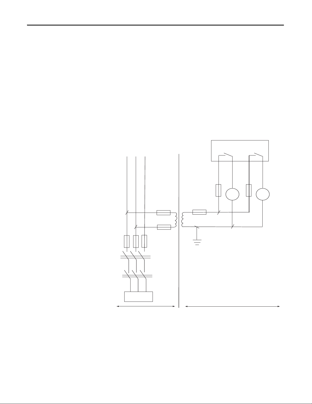
1791DS-IB4XOW4 Module
L1 L2 L3
400V AC/ 230V AC
III Over-voltage Category II
F1…F8 - Fuses
MA, MB - Electromagnetic Switches
TR1 - Insulated Transformer
44151
F6
F7
F8
F2
F1
TR1
F3
F4
F5
MA
MB
MA
MB
Load
For 1791DS-IB4XOW4 modules, follow these instructions on isolating
transformer use. Refer to the isolating transformer figure.
• Use an isolating transformer to isolate between over-voltage category III
and II, such as TR1, to conform to IEC 60742.
• Be sure the insulation between first input and secondary output satisfies at
least basic insulation of over-voltage category III.
• Be sure one side of a secondary output of the isolating transformer is
grounded to prevent electric shock to personnel due to a short to ground
or short to the frame of the isolating transformer.
• Insert fuses, in case of a short to the frame, to protect the isolating
transformer and prevent electric shock to personnel, per transformer
specifications, at points such as F1, F2, and F3.
Figure 1 - Use of Isolating Transformer
16 Rockwell Automation Publication 1791DS-UM001J-EN-P - May 2013
Page 17

About the Modules Chapter 1
Precautions to Mount, Wire,
and Clean
Observe these precautions to prevent operation failure, malfunctions, or
undesirable effects on product performance.
Follow these precautions when mounting modules:
• Use DIN rail that is 35 mm (1.38 in.) wide to mount the module into the
control panel.
• Mount modules to DIN rail securely.
• Leave at least 50 mm (1.96 in.) above and below the module to allow
adequate ventilation and room for wiring for 1791DS-IB12, 1791DSIB8XOB8, and 1791DS-IB4XOW4 modules.
• Leave at least 15 mm (0.6 in.) around the module to allow adequate
ventilation and room for wiring for 1732DS-IB8, 1732DS-IB8XOBV4,
1791DS-IB8XOBV4, and 1791DS-IB16 modules.
Follow these precautions when wiring modules:
• Do not place communication lines and I/O lines in the same wiring duct
or track as high voltage lines.
• Wire correctly after confirming the signal names of all terminals.
• Do not remove the shield from a module before wiring, but always remove
the shield after completing wiring to be sure of proper heat dispersion for
1791DS-IB12, 1791DS-IB8XOB8, and 1791DS-IB4XOW4 modules.
• Follow torquing specifications as indicated in the installation instructions.
I/O Module Overview
When cleaning modules, do not use the following:
• Thinner
• Benzene
• Acetone
The Guard I/O modules implement the CIP-safety protocol extensions over
DeviceNet networks and provide various features for a safety system.
Use the modules to construct a safety-control network system that meets the
requirements up to Safety Integrity Level 3 (SIL 3) as defined in IEC 61508,
Functional Safety of Electrical, Electronic, and Programmable Electronic Safetyrelated Systems, and the requirements for Safety Category 4 of the EN 954-1
standard, Safety of machinery - Safety related parts of control systems. All
1791DS modules can be mounted vertically or horizontally.
Remote I/O communication for safety I/O data are performed through safety
connections supporting CIP safety over a DeviceNet network. Data processing is
performed in the safety controller.
The status and fault diagnostics of Guard I/O modules are monitored by a safety
controller through a safety connection using a new or existing DeviceNet
network.
Rockwell Automation Publication 1791DS-UM001J-EN-P - May 2013 17
Page 18

Chapter 1 About the Modules
The following is a list of features common to Guard I/O modules:
• CIP-safety and DeviceNet protocol conformance
• Safety inputs
– Safety devices, such as emergency stop push buttons, gate switches, and
safety light curtains, can be connected.
– Dual-channel mode evaluates consistency between two input signals
(channels), which allows use of the module for Safety Category 3 and 4.
– The time of a logical discrepancy between two channels can be
monitored using a discrepancy time setting.
– An external wiring short-circuit check is possible when inputs are wired
in combination with test outputs. The module must be wired in
combination with test outputs when this function is used.
– Independently adjustable on and off delay is available per channel.
• Te st ou tp u t s
– Separate test outputs are provided for short circuit detection of a safety
input (or inputs).
– Power (24V) can be supplied to devices, such as safety sensors.
– Test outputs can be configured as standard outputs.
– All Guard I/O modules have numerous test outputs, of which some can
be used for broken wire detection of a muting lamp.
• Safety outputs
– Solid state outputs
• Dual-channel mode evaluates consistency between two output signals
(channels).
• Safety outputs can be pulse tested to detect field wiring shorts to 24V
DC.
• All 1791DS-IB8XOBV4 modules’ safety outputs use pulse testing to
detect a short to 24V DC on the safety source output (P), and a short to
0V DC on the safety sink output (M).
– Relay Outputs
• Dual-channel mode evaluates consistency between two output signals
(channels).
• Up to 2 A is provided per output point.
• Safety relays can be replaced.
• I/O status data - In addition to I/O data, the module includes status data
for monitoring I/O circuits.
• Security - The configuration information of the module can be protected
by a password.
• Removable I/O connectors - I/O connectors support mechanical keying.
18 Rockwell Automation Publication 1791DS-UM001J-EN-P - May 2013
Page 19
About the Modules Chapter 1
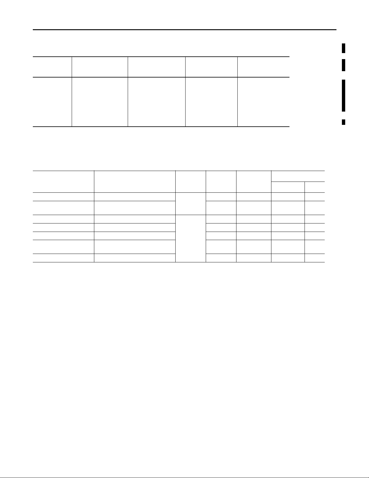
Programming Requirements
Cat. No. Studio 5000 Environment
1732DS-IB8,
1732DS-IB8XOBV4,
1791DS-IB12,
1791DS-IB8XOB8,
1791DS-IB4XOW4,
1791DS-IB8XOBV4,
1791DS-IB16
(1) This version or later.
(1)
Versi on
21 17 8 2.51
Guard I/O Catalog Numbers
Cat. No. Description Enclosure Type
1732DS-IB8 Safety input module Meets IP64/65/6788 - -
1732DS-IB8XOBV4 Safety I/O module with solid state outputs 8 8 4 bipolar
1791DS-IB12 Safety input module Meets IP20 12 4 - -
1791DS-IB8XOB8 Safety I/O module with solid state outputs 8 4 8 -
1791DS-IB4XOW4 Safety I/O module with relay outputs 4 4 - 4
1791DS-IB8XOBV4 Safety I/O module with solid state outputs 8 8 4 bipolar
1791DS-IB16 Safety input module 16 16 - -
Use the minimum software versions listed here.
RSLogix 5000 Software
(1)
Versi on
(EtherNet/IP Network)
RSNetWorx for DeviceNet
Software Version
(DeviceNet Network)
(1)
RSLinx Software
(1)
Vers ion
See the table for a listing of the types of Guard I/O modules.
Rating
Safety Inputs Test Outputs Safety Outputs
Solid State Relays
-
pairs
-
pairs
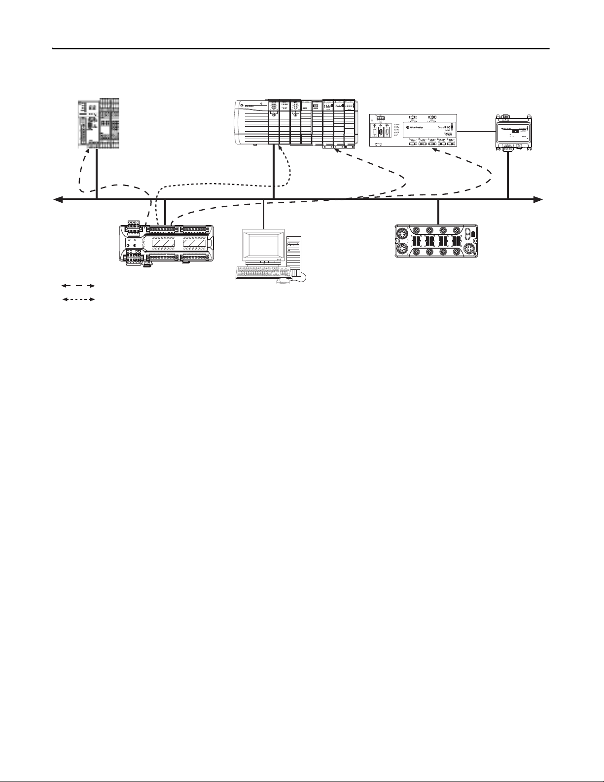
About CIP Safety in
DeviceNet Safety
Architectures
Use Guard I/O modules in DeviceNet safety architectures as shown below.
The Guard I/O family is a set of I/O modules that when connected to a
DeviceNet safety network are suitable for applications up to SIL3, as defined in
the IEC 61508 standard, and Safety Category 4, as defined in the EN 954-1
standard.
Rockwell Automation Publication 1791DS-UM001J-EN-P - May 2013 19
Page 20
Chapter 1 About the Modules
44196
ArmorBlock Guard I/O
Module
Compac tBlock
Guard I/O Module
RSNetWorx,
Studio 5000, and
RSLogixGuard Plus Software
SmartGuard 600
Control ler
Safety Communication
Standard Communication
DeviceNet
Scanner
Interface
DeviceNet Network
Logix Co ntroller
Logix Co ntroller
GuardLogix Controller
Guard PLC Controller
Figure 2 - Guard I/O Modules in DeviceNet Safety Architectures
Safety controllers control the safety outputs. Safety or standard PLC controllers
can control the standard outputs.
20 Rockwell Automation Publication 1791DS-UM001J-EN-P - May 2013
Page 21
About the Modules Chapter 1
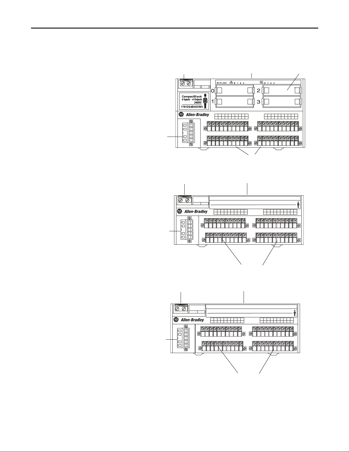
Node Address Switches
Safety Relay
I/O Connections
44195
Communication
Conne ctor
Status Indicators
Node Address Switches
Status Indicators
Communication
Connector
44091
I/O Connections
Node Address Switches
Status Indicators
Communication
Conne ctor
44091
I/O Connections
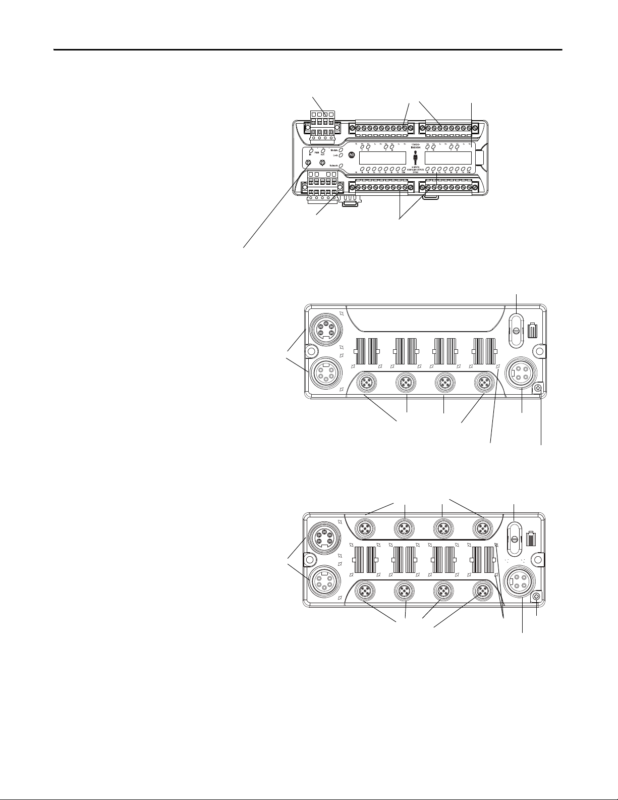
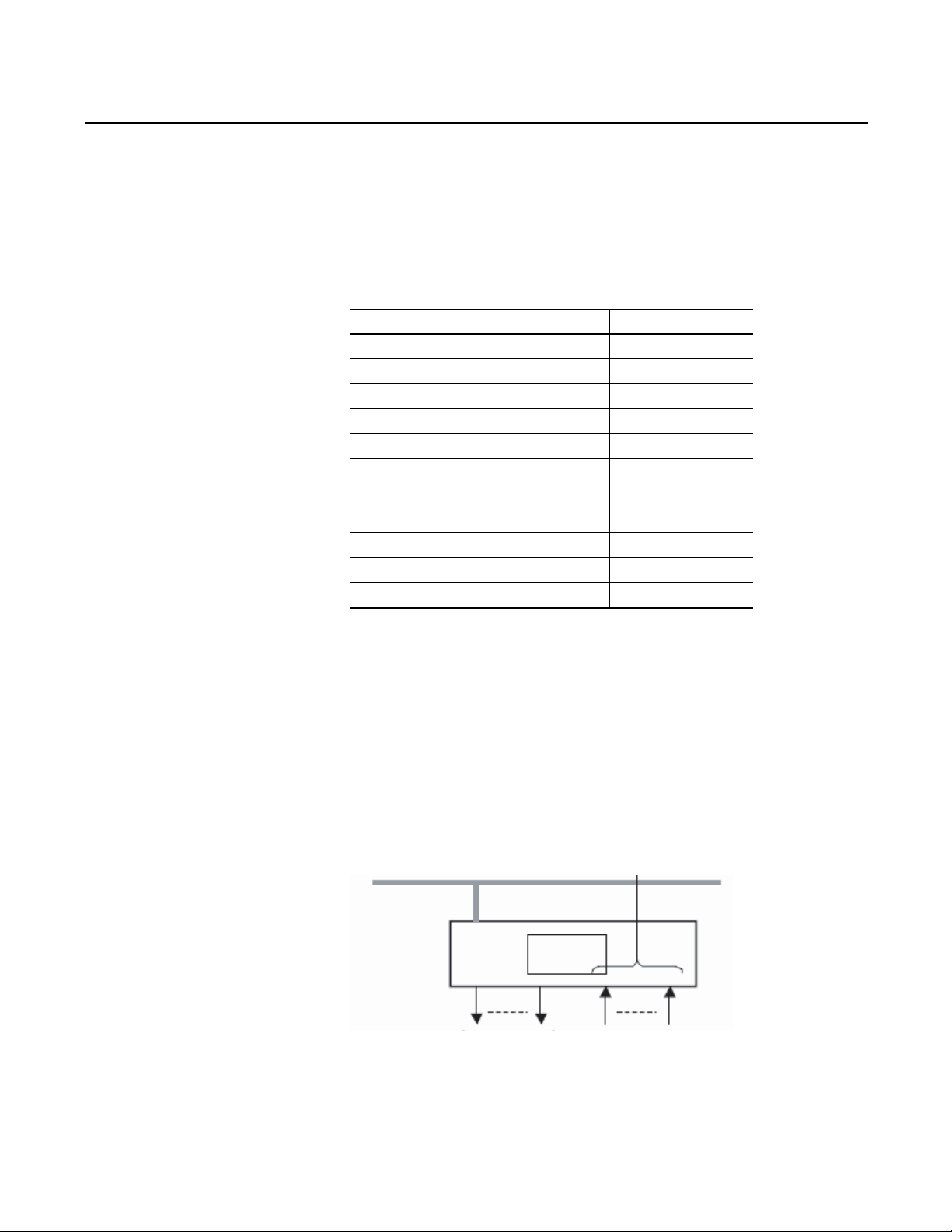
Identify Major Parts of the
Modules
See the figures for module identification. For pin-out information, refer to the
relevant installation instructions.
Figure 3 - 1791DS-IB4XOW4 Module Identification
Figure 4 - 1791DS-IB8XOB8 Module Identification
MS NS LOCK
1791DS-IB8XOB8
IN
0 1 2 3 4 5 6 7 0 1 2 3 4 5 6 7
PWR
OUT
PWR
8 Inputs - 8 Outputs 24VDC
CompactBlock
Figure 5 - 1791DS-IB12 Module Identification
IN
MS NS LOCK
1791DS-IB12
Rockwell Automation Publication 1791DS-UM001J-EN-P - May 2013 21
0 1 2 3 4 5 6 7 8 9 10 1 1
PWR
CompactBlock
12 Inputs 24VDC
Page 22
Chapter 1 About the Modules
NODE
ADR
8
2
4
6
0
8
2
4
6
0
X1X10
Node Address Switches
I/O Connectors (input)
44224
Communicat ion Connec tor
Status Indicators
Power Connector
I/O Connectors (output)
44123
Commu nication
Conne ctor
Node Address Switches
I/O
Power
Inputs
Status Indicators
FE
Communication
Conne ctor
Node Address
Switches
Outputs
Inputs
I/O Power
44122
Status Indicators
FE
Figure 6 - 1791DS-IB8XOBV4 Module Identification
Figure 7 - 1732DS-IB8 Module Identification
22 Rockwell Automation Publication 1791DS-UM001J-EN-P - May 2013
Figure 8 - 1732DS-IB8XOBV4 Module Identification
Page 23
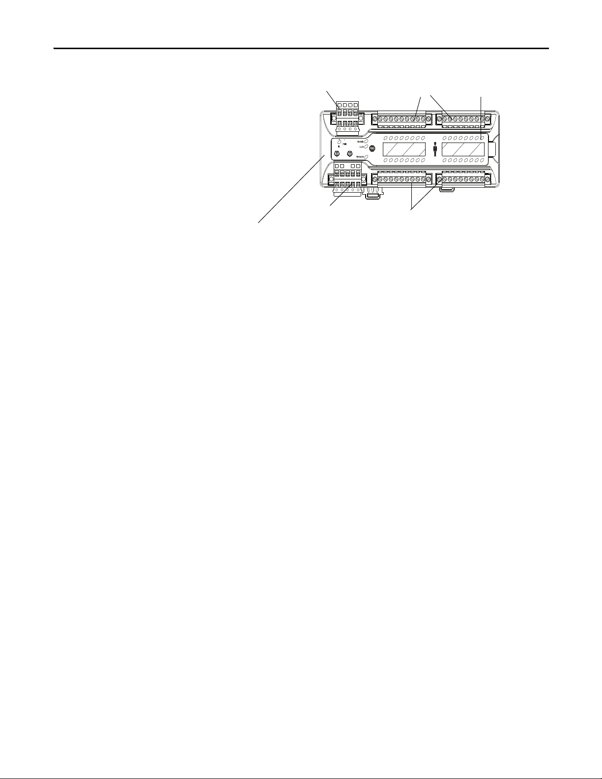
Figure 9 - 1791DS-IB16 Module Identification
NC NC
NODE
ADR
8
2
4
6
0
8
2
4
6
0
X1X10
FE I8 I9 T8 T9 I10 I11 T10 T11M
1791DS IB16
16 INPUTS
24 Vdc
FE I0 I1 T0 T1 I2 I3 T2 T3M
I4 I5 T4 T5 I6 I7 T6 T7M
I12 I13 T12 T13 I14 I15 T 14 T15M
Node Address Switches
I/O Connectors (input)
44118
Communication Connector
Status Indicators
Power Connector
I/O Connectors (input)
About the Modules Chapter 1
Rockwell Automation Publication 1791DS-UM001J-EN-P - May 2013 23
Page 24

Chapter 1 About the Modules
Notes:
24 Rockwell Automation Publication 1791DS-UM001J-EN-P - May 2013
Page 25
Chapter 2
Output Off
Input
Inputs to Network
DeviceNet Network
Safety
Status
44076
Understand the Operation of Safety Functions
Top ic P ag e
Safety I/O Modules 25
Self-diagnostic Functions 26
Configuration Lock 26
I/O Status Data 26
Safety Inputs 26
Test Outputs Configured as Muting Outputs 34
Safety Outputs 36
Controlling D evices 38
Safety Precautions 38
Legislation and Standards 39
EC Directives 41
Safety I/O Modules
Read this chapter for information related to the safety functions of the modules.
Also included is a brief overview on international standards and directives that
you should be familiar with.
The following status is the safety state of the Guard I/O modules:
• Safety outputs: off
• Safety input data to network: off
Figure 10 - Safety Status
Rockwell Automation Publication 1791DS-UM001J-EN-P - May 2013 25
Page 26

Chapter 2 Understand the Operation of Safety Functions
The module is designed for use in applications where the safety state is the off
state.
Self-diagnostic Functions
Configuration Lock
I/O Status Data
Self-diagnostics are performed when the power is turned on and periodically
during operation. If a fatal internal module error occurs, the red module status
(MS) indicator is illuminated, and the safety outputs and input data and status to
the network turn off.
After configuration data has been downloaded and verified, the configuration
data within the module can be protected by using RSNetWorx for DeviceNet
software.
For GuardLogix systems, this status indicator is not used. Reference information
about safety signatures in the GuardLogix Controller Systems Safety Reference
Manual, publication 1756-RM093
Safety Reference Manual, publication 1756-RM099
In addition to I/O data, the module provides status data for monitoring the I/O
circuits. The status data includes the following data, which can be read by the
controllers. Note that 1 = ON/Normal and 0 = OFF/Fault/Alarm.
• Individual Point Input Status
• Combined Input Status
• Individual Point Output Status
• Combined Output Status
• Individual Test Output Status
• Individual Output Readback (actual ON/OFF state of the outputs)
or the GuardLogix 5570 Controller System
.
Status data indicates whether each safety input, safety output, or test output is
normal (normal status: ON, faulted status: OFF). For fatal errors,
communication connections may be broken, so the status data cannot be read.
Status bits are OFF in the GuardLogix data table when the connection is lost.
Combined status is provided by an AND of the status of all safety inputs or all
safety outputs. When all inputs or outputs are normal the respective combined
status is ON. When one or more of them has an error, the respective combined
status is OFF. This is known as the combined safety input status or combinedsafety output status.
Safety Inputs
26 Rockwell Automation Publication 1791DS-UM001J-EN-P - May 2013
Read this section for information about safety inputs and their associated test
outputs. A safety input may be used with test outputs. Safety inputs are used to
monitor safety input devices.
Page 27
Understand the Operation of Safety Functions Chapter 2
24V DC Output with Test Pulse
External Contact
Safety Input
Terminal
24V
44078
X
OUT
Y
On
Off
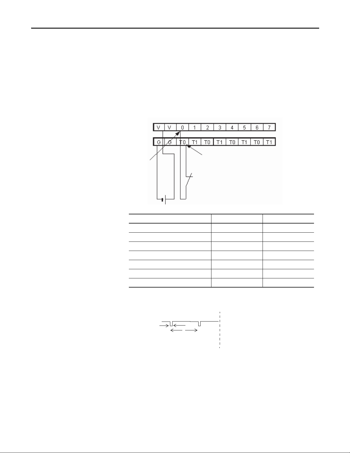
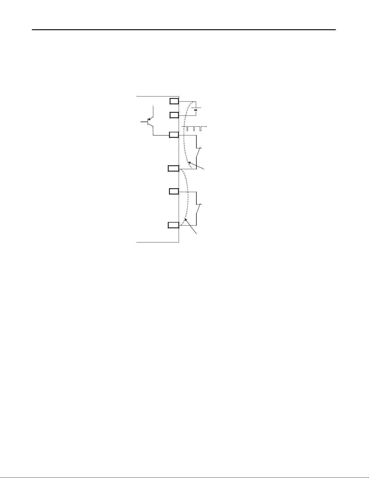
Using a Test Output with a Safety Input
A test output can be used in combination with a safety input for short circuit
detection. Configure the test output as a pulse test source and associate it to a
specific safety input.
The test output can also be configured for a power supply to source 24V DC for
an external device, for example, a light curtain.
Figure 11 - Example Use of a 1791DS-IB12 Module
Cat. No. Pulse Width (X) Pulse Period (Y )
1732DS-IB8 500 μs 600 ms
1732DS-IB8XOBV4 500 μs 600 ms
1791DS-IB12 700 μs 648 ms
1791DS-IB8XOB8 700 μs 648 ms
1791DS-IB4XOW4 700 μs 648 ms
1791DS-IB8XOBV4 500 μs 600 ms
1791DS-IB16 500 μs 600 ms
Figure 12 - Test Pulse in a Cycle
Rockwell Automation Publication 1791DS-UM001J-EN-P - May 2013 27
Page 28
Chapter 2 Understand the Operation of Safety Functions
External Contact
Short-circuit Between Input Signal Lines and Power
Supply (positive side)
External Contact
Short-circuit Between Input Signal Lines
44079
24V
V
G
T0
IN0
T1
IN1
24V
0V
When the external input contact is closed, a test pulse is output from the test
output terminal to diagnose the field wiring and input circuitry. Using this
function, short-circuits between input signal lines and the power supply (positive
side), and short-circuits between input signal lines can be detected.
Figure 13 - Short-circuit Between Input Signal Lines
28 Rockwell Automation Publication 1791DS-UM001J-EN-P - May 2013
Page 29
Understand the Operation of Safety Functions Chapter 2
24V
0V
T0
Input Terminal 0
External Device
Faul t De tect ed
Remote
I/O
Data
ON
OFF
ON
OFF
ON
OFF
ON
OFF
24V
0V
ON
OFF
T0
Safety Input
Status 0
Fault Detection
Remote
I/O
Data
ON
OFF
ON
OFF
ON
OFF
Safety Input
Status 0
Safety Input 0
Safety Input 0
Input Terminal 0
Normal Operation
External Device
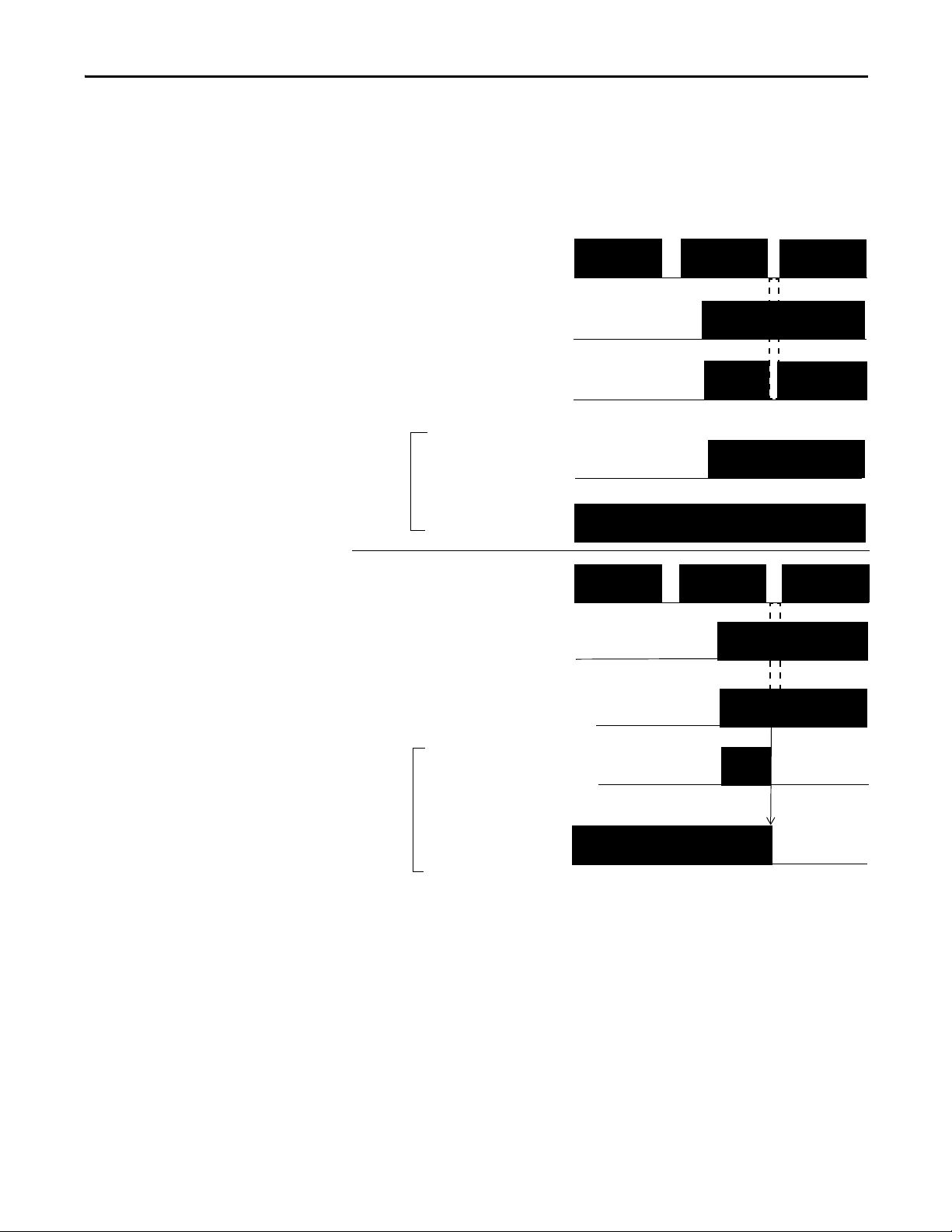
Single Channel Mode
If an error is detected, safety input data and safety input status turn off.
Figure 14 - Normal Operation and Fault Detection (not to scale)
Rockwell Automation Publication 1791DS-UM001J-EN-P - May 2013 29
Page 30

Chapter 2 Understand the Operation of Safety Functions
IMPORTANT
IMPORTANT
Dual-channel Mode and Discrepancy Time
To support redundant-channel safety devices, the consistency between signals on
two channels can be evaluated. Either equivalent or complementary can be
selected. This function monitors the time during which there is a discrepancy
between the two channels.
If the length of the discrepancy exceeds the configured discrepancy time
(0…65,530 ms in increments of 10 ms), the safety input data and the individualsafety input status turns off for both channels.
The dual-channel function is used with two consecutive inputs that are
paired together, starting at an even input number, such as inputs 0 and 1, 2
and 3, and so on.
Do not set the discrepancy time longer than necessary. The purpose of the
discrepancy time is to allow for normal differences between contact
switching when demands are placed on safety inputs. For this testing to
operate correctly, only a single demand on the safety input is expected
during the discrepancy time. If the discrepancy time is set too high, and
multiple demands occur during this time, then both safety input channels
will fault.
This table shows the relation between input terminal states and controller input
data and status.
Table 1 - Terminal Input Status and Controller I/O Data
Dual-channel Mode Input Terminal Controller Input Data and Status Dual- channel
IN0 IN1 Safety
Dual-channels, Equivalent OFF OFF OFF OFF ON ON OFF Normal
OFF ON OFF OFF OFF OFF OFF Fault
ON OFF OFF OFF OFF OFF OFF Fault
ON ON ON ON ON ON ON Normal
Dual-channels,
Complementary
OFF OFF OFF ON OFF OFF OFF Fault
OFF ON OFF ON ON ON OFF Normal
ON OFF ON OFF ON ON ON Normal
ON ON OFF ON OFF OFF OFF Fault
Input 0 Data
Safety
Input 1 Data
Safety
Input 0 Status
Safety
Input 1 Status
Resultant
Data
Dualchannel
Resultant
Status
Dual-channels, Equivalent
In Equivalent mode, both inputs of a pair should typically be in the same
(equivalent) state. When a transition occurs in one channel of the pair prior to
the transition of the second channel of the pair, a discrepancy occurs. If the
second channel transitions to the appropriate state prior to the discrepancy time
elapsing, the inputs are considered equivalent. If the second transition does not
occur before the discrepancy time elapses, the channels will fault. In the fault state
the input and status for both channels are set low (off). When configured as an
30 Rockwell Automation Publication 1791DS-UM001J-EN-P - May 2013
Page 31

Understand the Operation of Safety Functions Chapter 2
ON
OFF
IN0
Safety Input 0
IN1
Faul t Dete cted
Discrepancy Time
Remote
I/O
Data
ON
OFF
ON
OFF
ON
OFF
ON
OFF
ON
OFF
ON
OFF
IN0
Safety Input
Status 0, 1
IN1
Fault Detection
Remote
I/O
Data
ON
OFF
ON
OFF
ON
OFF
Discrepancy Time
Safety Input
Status 0, 1
Safety Input 1
Safety Input 1
Safety Input 0
Normal Operation
equivalent dual pair, the data bits for both channels will always be sent to the
controller as equivalent, both high or both low.
Figure 15 - Equivalent, Normal Operation and Fault Detection (not to scale)
Dual-channels, Complementary
In Complementary mode, the inputs of a pair should typically be in the opposite
(complementary) state. When a transition occurs in one channel of the pair prior
to the transition of the second channel of the pair, a discrepancy occurs. If the
second channel transitions to the appropriate state prior to the discrepancy time
elapsing, the inputs are considered complementary.
If the second transition does not occur before the discrepancy time elapses, the
channels will fault. The fault state of complementary inputs is the evennumbered input turned off and the odd-numbered input turned on. Note that if
faulted, both channel status bits are set low. When configured as a
Rockwell Automation Publication 1791DS-UM001J-EN-P - May 2013 31
Page 32

Chapter 2 Understand the Operation of Safety Functions
ON
OFF
IN0
Safety Input 0
IN1
Faul t Dete cted
Discrepancy Time
Remote
I/O
Data
ON
OFF
ON
OFF
ON
OFF
ON
OFF
ON
OFF
ON
OFF
IN0
Safety Input
Status 0, 1
IN1
Fault Detection
Remote
I/O
Data
ON
OFF
ON
OFF
ON
OFF
Discrepancy Time
Safety Input
Status 0, 1
Safety Input 1
Safety Input 1
Safety Input 0
Normal
Operation
complementary dual-channel pair, the data bits for both channels will always be
sent to the controller in complementary, or opposite states.
Figure 16 - Complementary, Normal Operation and Fault Detection (not to scale)
32 Rockwell Automation Publication 1791DS-UM001J-EN-P - May 2013
Page 33

Understand the Operation of Safety Functions Chapter 2
ON
OFF
ON
OFF
Remote I/O
Data Safety
Input
ON-delay
44094
On-delay
Input Signal
ON
OFF
ON
OFF
Remote I/O Data
Safety Input
OFF
ON
OFF
Safety Input
Input Signal
OFF-delay
44095
Remote I/O Data
Safety Input
Input Signal
ON
OFF
ON
OFF
Off-delay
Safety Input Fault Recovery
If an error is detected, the safety input data remains in the off state. Follow this
procedure to activate the safety input data again.
1. Remove the cause of the error.
2. Place the safety input (or safety inputs) into the safe state.
The safety input status turns on (fault cleared) after the input-error latch
time has elapsed and the I/O indicator (red) turns off. The input data can
now be controlled.
Input Delays
On-delay - An input signal is treated as Logic 0 during the on-delay time (0…126
ms, in increments of 6 ms) after the input contact’s rising edge. The input turns
on only if the input contact remains on after the on-delay time has elapsed. This
helps prevent rapid changes of the input data due to contact bounce.
Figure 17 - On-delay
Off-delay - An input signal is treated as Logic 1 during the off-delay time (0…126
ms, in increments of 6 ms) after the input contact’s falling edge. The input turns
off only if the input contact remains off after the off delay time has elapsed. This
helps prevent rapid changes of the input data due to contact bounce.
Figure 18 - Off-delay
Rockwell Automation Publication 1791DS-UM001J-EN-P - May 2013 33
Page 34

Chapter 2 Understand the Operation of Safety Functions
Test Outputs Configured as
Muting Outputs
When test outputs are used as muting outputs, typically for a muting lamp, a
circuit test is used to diagnose whether the circuit and lamp are operational. The
muting circuit test is run every 3 seconds, regardless of whether the circuit is logic
HI or LO. This could cause your muting output to flicker during normal
operation when it is logic LO.
The muting circuit test must fail twice in succession when the muting circuit is
logically HI, before a fault is declared. The results of the muting circuit test do
not affect the muting status when the circuit is logically LO.
A muting circuit fault will cause the muting status bit to go LO.
A muting circuit fault is declared 3…6 seconds after the fault occurs if the muting
circuit is logically HI for at least 6 seconds, because of the 3-second test interval
and that the muting circuit test must fail twice in successession. If the muting
circuit is logically HI for less than 6 seconds during a machine cycle, then the
asynchronous test and program scans could cause the fault detection to be
delayed for several machine cycles.
There is a difference in the operation of the muting status between some of the
DeviceNet safety I/O modules. This table shows the operation of the muting
status of all modules.
Cat. No. Lamp Circuit Description
1791DS-IB16
1791DS-IB8XOBV4
1732DS-IB8
1732DS-IB8XOBV4
1791DS-IB12 HI Good Muting status HI/1
1791DS-IB8XOB8
1791DS-IB4XOW4 Bad Muting status Lo 1 second/HI 5 seconds (repeats)
(1) This module’s muting status bit goes LO when a fault occurs or when the circuit is logically LO.
(1)
(1)
(1)
(1)
HI Good Muting status HI/1
Bad Muting status LO 1 second/HI 5 seconds (repeats)
LO status typically appears 3…6 seconds after fault
Muting status resets automatically
LO G ood M utin g status LO/0
Bad Muting status LO/0
Muting status resets automatically
LO Good Muting status HI/1
Bad Muting status HI/1
For catalog numbers 1791DS-IB16, 1791DS-IB8XOBV4, 1732DS-IB8, and
1732DS-IB8XOBV4, when using these GuardLogix safety application
instructions that monitor muting, should include the following codes to operate
properly when the muting status bit goes LO if the circuit is logically LO:
• DCSTM
• FSBM
• TSAM
• TSSM
34 Rockwell Automation Publication 1791DS-UM001J-EN-P - May 2013
Page 35

Understand the Operation of Safety Functions Chapter 2
In this code, the actual muting status bit is used in the first rung, and
the DN bit of the timer is used in the muting status parameter of the
instruction. The actual test output data bit is used in both the first and
last rungs.
Rockwell Automation Publication 1791DS-UM001J-EN-P - May 2013 35
Page 36

Chapter 2 Understand the Operation of Safety Functions
IMPORTANT
44096
X
Y
OUT
On
Off
Safety Outputs
Read this section for information about safety outputs.
Safety Output with Test Pulse
When the safety output is on, the safety output can be test pulsed, as shown in
the figure and table.
Using this function, short-circuits between output signal lines and the power
supply (positive side) and short-circuits between output signal lines can be
detected. If an error is detected, the safety output data and individual safety
output status turn off.
Cat. No. Pulse Width (X) Pulse Period (Y )
1732DS-IB8 Not applicable Not applicable
1732DS-IB8XOBV4 700 μs 600 ms
1791DS-IB12 Not applicable Not applicable
1791DS-IB8XOB8 470 μs 648 ms
1791DS-IB4XOW4 Not applicable Not applicable
1791DS-IB8XOBV4 700 μs 600 ms
1791DS-IB16 Not applicable Not applicable
Figure 19 - Test Pulse in a Cycle
To prevent the test pulse from causing the connected device to
malfunction, pay careful attention to the input response time of the device.
36 Rockwell Automation Publication 1791DS-UM001J-EN-P - May 2013
Page 37

Understand the Operation of Safety Functions Chapter 2
ON
OFF
OUT0
Safety Output
Status 0, 1
OUT0
OUT1
OUT1
Safety Output
Status 0, 1
Fault Detection
Error
Detected
Remote
I/O
Data
Remote
I/O
Data
ON
OFF
ON
OFF
ON
OFF
ON
OFF
ON
OFF
Normal Oper ation
Dual-channel Setting
When the data of both channels is in the on state, and neither channel has a fault,
the outputs are turned on. The status is normal. If a fault is detected on one
channel, the safety output data and individual safety output status turn off for
both channels.
Figure 20 - Dual-channel Setting (not to scale)
Safety Output Fault Recovery
If a fault is detected, the safety outputs are switched off and remain in the off
state. Follow this procedure to activate the safety output data again.
1. Remove the cause of the error.
2. Place the safety output (or safety outputs) into the safety state.
The safety output status turns on (fault cleared) when the output-error
latch time has elapsed. The I/O indicator (red) turns off. The output data
can now be controlled.
Rockwell Automation Publication 1791DS-UM001J-EN-P - May 2013 37
Page 38

Chapter 2 Understand the Operation of Safety Functions
Controlling Devices
See this table for information about controlling devices.
ATTENTION: Use appropriate devices as indicated in the Controlling
Device Requirements table. Serious injury may occur due to loss of
safety functions.
Table 2 - Controlling Device Requirements
Device Requirement Allen-Bradley Bulletin Safety Components
Emergency stop switches Use approved devices with direct opening mechanisms complying with IEC/EN
Door interlocking switches,
limit switches
Safety sensors Use approved devices complying with the relevant product standards,
Relays with forcibly- guided
contacts,
contactors
Other devices Evaluate whether devices used are appropriate to satisfy the requirements of
60947-5-1.
Use approved devices with direct opening mechanisms complying with IEC/EN
60947-5-1 and capable of switching microloads of 24V DC, 3 mA.
regulations, and rules in the country where used.
Use approved devices with forcibly-guided contacts complying with EN 50205. For
feedback purposes, use devices with contacts capable of switching micro loads of
24V DC, 3 mA.
safety category levels.
Bulletin 800F, 800T
Bulletin 440K, 440G, 440H for interlock switch
Bulletin 440P, 802T for limit switch
Guardmaster products, refer to specific product publications for
details
Bulletin 700S, 100S
-
Safety Precautions
ATTENTION: As serious injury may occur due to loss of required safety
function, follow these safety precautions.
• Do not use test outputs of the modules as safety outputs.
• Do not use DeviceNet standard I/O data or explicit message data as
safety data.
• Do not use LED status indicators on the I/O modules for safety
operations.
• Do not connect loads beyond the rated value to the safety outputs.
• Wire the Guard I/O modules properly so that 24V DC line does not touch
the safety outputs accidentally or unintentionally.
• Clear previous configuration data before connecting devices to the
network.
• Set unique DeviceNet node addresses before connecting devices to the
network.
• Perform testing to confirm that all of the device configuration data and
operation is correct before starting system operation.
• When replacing a device, configure the replacement device suitably and
confirm that it operates correctly.
• When installing or replacing modules, clear any previous configuration
before connecting input or output power to the device.
38 Rockwell Automation Publication 1791DS-UM001J-EN-P - May 2013
Page 39

Understand the Operation of Safety Functions Chapter 2
Legislation and Standards
Read this section to familiarize yourself with related legislation and standards
information. Relevant international standards include the following:
• IEC 61508 (SIL 1-3)
• IEC 61131-2
• IEC 60204-1
• IEC 61000-6-2
• IEC 61000-6-4
• IEC 62061
The modules received the following certification from ODVA, when product is
marked.
• DeviceNet Conformance Test
• DeviceNet Safety Conformance Test
Europe
In Europe, Guard I/O modules may be subject to the European Union (EU)
Machinery Directive Annex IV, B, Safety Components, items 1 and 2. The type
approval of TUV-Rheinland addresses compliance to applicable requirements of
the following directives and standards.
• EU legislation
– Machinery Directive
– Low-voltage Directive
– EMC Directive
• European standards
– EN 61508 (SIL1-3)
– EN 954-1 (Category 4, 3, 2, 1, B)
– EN 61131-2
– EN 418
– EN 60204-1
– IEC 61000-6-2
– IEC 61000-6-4
– IEC 13849
Rockwell Automation Publication 1791DS-UM001J-EN-P - May 2013 39
Page 40

Chapter 2 Understand the Operation of Safety Functions
North America
In North America, the TUV-Rheinland type approval includes Guard I/O
compliance to the relevant standards and related information including the
following:
• U.S. standards - ANSI RIA15.06, ANSI B11.19, NFPA 79
• The modules are UL-certified functionally safe and carry the NRGF label,
when product is marked.
• The modules received UL Listing to standards of U.S. and Canada when
product is marked.
Japan
In Japan, type test requirements are provided in Article 44 of the Industrial Safety
and Health Law. These requirements apply to complete systems and cannot be
applied to a module by itself. Accordingly, to use the module in Japan as a safety
device for press machine or shearing tool pursuant to Article 42 of the abovementioned law, it is necessary to apply for testing of the entire system.
40 Rockwell Automation Publication 1791DS-UM001J-EN-P - May 2013
Page 41

Understand the Operation of Safety Functions Chapter 2
EC Directives
These products conform to the EMC Directive and Low-voltage Directive. For
additional information, refer to the relevant installation instructions.
EMC Directive
Rockwell Automation devices that comply with EC directives also conform to
the related EMC standards so that they can more easily be built into other devices
or the overall machine. The actual products have been checked for conformity to
EMC standards. Whether they conform to the standards in the system used by
the customer, however, must be confirmed by the customer.
EMC-related performance of Rockwell Automation devices that comply with
EMC directive vary depending on the configuration, wiring, and other
conditions of the equipment or control panel in which the Rockwell Automation
devices are installed. The customer must, therefore, perform the final check to
confirm that devices and the overall machine conform to EMC standards.
Compliance with EC Directives
DeviceNet products that comply with EC directives must be installed as follows:
• All Type IP20 DeviceNet units must be installed within control panels.
• Use reinforced insulation or double insulation for the DC power supplies
used for the communication power supply, internal- circuit power supply,
and the I/O power supplies.
• DeviceNet products that comply with EC directives also conform to the
Common Emission Standard (EN 50081-2). Radiated emission
characteristics (10-m regulations) may vary depending on the
configuration of the control panel used, other devices connected to the
control panel, wiring, and other conditions. You must confirm that the
overall machine or equipment complies with EC directives.
Rockwell Automation Publication 1791DS-UM001J-EN-P - May 2013 41
Page 42

Chapter 2 Understand the Operation of Safety Functions
EXAMPLE
EXAMPLE
EXAMPLE
31522-M
13
(0.51)
29
(1.14)
30
(1.18)
33
(1.30)
Dimensions are in mm (in.).
Examples to Reduce Noise
These examples show how to reduce noise in 1791DS-IB12, 1791DS-IB8XOB8,
and 1791DS-IB4XOW4 modules.
Reduce electrical noise from the communication cable by installing a ferrite
core on the communication cable within 10 cm (3.93 in.) of the DeviceNet
master unit. Use Ferrite Core (Data Line Filter) LF130B, manufactured by
Easy Magnet Co., or an equivalent.
Impedance Specifications
ImpedanceValue
25 MHz 100 MHz
Ω 250 Ω
156
Ferrite Core
Wire the control panel with cables that are as short as possible and ground
to 100 Ω or less.
Keep DeviceNet communication cables as short as possible and ground to
100 Ω or less.
42 Rockwell Automation Publication 1791DS-UM001J-EN-P - May 2013
Page 43

Install and Connect Your Modules
Top ic P ag e
Considerations for Module Installation 43
Install the Module 44
Connect I/O Power and I/O Cables 45
Connect Communication Connectors 46
Set the Node Address 46
Chapter 3
Considerations for Module
Installation
The communication baud rate of the entire network is determined by the
communication baud rate of the master unit. The communication baud rate does
not need to be set for each module.
ATTENTION: You can configure Test Outputs to be used as standard
outputs. You can connect actuators to Test Output points that are
expecting a Standard configuration.
ATTENTION: Test Output points configured as Pulse Test or Power
Supply become active whenever you apply input power to the module.
These configured functions are independent of the I/O connections to
the module.
ATT EN TI ON : If a module with Test Outputs configured as Pulse Test or Power
Supply is incorrectly installed in an application where actuators are connected
to these Test Output points, the actuators will be activated when network
power and input power are applied.
ATT EN TI ON : To prevent this possibility, use the following procedures:
• When installing a module, be sure that the module is correctly configured for
the application or in the out-of-box condition before applying input power.
• When replacing a module, be sure that the module is correctly configured for
the application or in the out-of-box condition before applying input power.
• Reset modules to their out-of-box condition when removing them from an
application.
• Be sure that all modules in replacement stock are in their out-of-box condition.
Rockwell Automation Publication 1791DS-UM001J-EN-P - May 2013 43
Page 44

Chapter 3 Install and Connect Your Modules
IMPORTANT
IMPORTANT
Wiring D uct
End Plate
End Plate
50 (1.96)
Min
35 (1.38) Dimensions are in mm (in.).
Wiring D uct
50 (1.96)
Min
Install the Module
Follow these instructions when installing a module:
• Use the module in an environment that is within the general
specifications.
• Use the 1791DS modules in an enclosure rated IP54 (IEC60529) or
higher.
• Use DIN rail that is 35 mm (1.38 in.) wide to mount the 1791DS
module in the control panel.
• Always use an end plate on each end of the 1791DS modules to
secure properly.
• Place other heat sources an appropriate distance away from the
module to maintain ambient temperatures around the module
below specified maximums.
See the figures for required spacing for module installation.
You can install modules horizontally or vertically.
Figure 21 - Module Installation (1791DS-IB12, 1791DS-IB8XOB8, and 1791DS-IB4XOW4 modules)
44 Rockwell Automation Publication 1791DS-UM001J-EN-P - May 2013
Page 45

Figure 22 - Module Installation
Dimensions are in mm (in.).
35 (1.38) DIN Rail
End Plate
1732DS-IB8XOBV4 module is shown.
1732DS-IB8 modules have identical dimensions.
1791DS-IB8XOBV4 module is shown.
1791DS-IB16 modules have identical dimensions.
Any Object
Any Object
Wiring Duc t
Wiring Duc t
15 (0.6) Min
15 (0.6) Min
15 (0.6) Min
15 (0.6) Min
44225
IMPORTANT
Install and Connect Your Modules Chapter 3
Connect I/O Power and
I/O Cables
See module installation instructions for wire type and wire size specifications.
• Note that I/O connectors are detachable.
• Tighten the screws on the I/O connector to the specified torque
setting as shown in the installation instructions.
• Since the I/O connector has a structure that helps prevent incorrect
wiring, make connections at the specified locations corresponding
to the terminal numbers.
• When present, do not remove debris shield from the module before
wiring.
• When present, always remove the debris shield after completing
wiring to be sure of proper heat dispersion.
Rockwell Automation Publication 1791DS-UM001J-EN-P - May 2013 45
Page 46

Chapter 3 Install and Connect Your Modules
IMPORTANT
IMPORTANT
Ten s D igi t One s Dig it
|
|
|
|
|
2
4
6
8
0
|
|
|
|
|
2
4
6
8
0
X1X10
Connect Communication
Connectors
Set the Node Address
Colored stickers on the communication connector match the colors of the wires
to be inserted. Check that the colors of the wires match when wiring the
connectors. The colors are as follows.
Color Signal
Red Power cable positive side (V+)
White High side of communication data (CAN_H)
-Shield
Blue Low side of communication data (CAN_L)
Black Power cable negative side (V-)
When connecting a communication connector with the module,
tighten the screws on the communication connector to the specified
torque setting as shown in the installation instructions.
The internal power for the module is supplied from the communication power
supply (V+, V-).
To set the node address, follow this procedure.
The node-address setting rotary switches must be set while the
communication power supply is turned off.
Figure 23 - Sample Node Address Digits
1. Set the node address by using the two rotary switches on the front panel of
the module, noting that the default setting is 63 and a value between
00…63 is valid for proper use.
2. Use the left rotary switch to set the tens digit of node address (decimal).
3. Use the right rotary switch to set the ones digit.
If the node address switches are set from 64…99, the node address needs to be set
from RSNetWorx for DeviceNet software.
46 Rockwell Automation Publication 1791DS-UM001J-EN-P - May 2013
Page 47

Chapter 4
Wiring Examples
Top ic P ag e
Input Examples 47
Source Output Examples 53
Bipolar Output Examples 55
Relay Output Examples 57
Tes t O ut put Ex amp le s 59
Read this chapter for information about wiring and safety categories. These
examples show wiring and configuration methods for various safety categories
used in SIL 2 or SIL 3 systems.
Input Examples
For other wiring examples, refer to the Safety Accelerator Toolkit for GuardLogix
Systems CD, publication SAFETY-CL002, or download toolkit files from the
Integrated Architecture Tools and Resources website at
http://www.ab.com/go/iatools
Read this section for input examples by application. For details, refer to the
installation instructions for each catalog number.
.
Rockwell Automation Publication 1791DS-UM001J-EN-P - May 2013 47
Page 48

Chapter 4 Wiring Example s
IN+
I0 I1 I2 T2
T0 T1
IN-
FE
E1
S1
S2
31802-M
E1: 24V DC Power Supply
S1: Emergency Stop Switch
(positive opening mechanism)
S2: Reset Switch
FE: Functional Earth Ground
Emergency Stop Switch Dual-channel Inputs with Manual Reset
This example shows wiring and controller configuration when using a Guard I/O
module with an emergency stop switch that has dual-channel inputs with manual
reset. If used in combination with the programs in a safety controller, this wiring
is Safety Category 4 in accordance with EN 954-1 wiring requirements.
Controller
Configuration
Safety Input 0 Safety Input 0 Channel Mode Test Pulse from Test Output
Safety Input 1 Safety Input 1 Channel Mode Test Pulse from Test Output
Safety Input 2 Safety Input 2 Channel Mode Used as Standard Input
Test Output 0 Test Output 0 Mode Pulse Test Output
Test Output 1 Test Output 1 Mode Pulse Test Output
Test Output 2 Test Output 2 Mode Power Supply Output
Parameter Name Configuration Setting
Sa fe ty I npu t 0 Test Sour ce Tes t O utp ut 0
Dual-channel Safety Input 0/1 Mode Dual-channel Equivalent
Dual-channel Safety Input 0/1 Discrepancy Time 100 ms (application dependent)
Sa fe ty I npu t 1 Test Sour ce Tes t O utp ut 1
Safety Input 2 Test Source Not Used
Dual-channel Safety Input 2/3 Mode Single Channel
48 Rockwell Automation Publication 1791DS-UM001J-EN-P - May 2013
Page 49

Wiring E xample s Chapter 4
E1: 24V DC Power Supply
S11 and S12: Two-hand
Switche s
Two-hand Monitor
This example shows wiring and controller configuration when using a Guard I/O
module with a two-hand monitor. If used in combination with the programs in a
safety controller, this wiring is Safety Category 4 in accordance with EN 954-1
wiring requirements.
S11
S12
Controller
I0 I2
I1 I3
T1
IN+ IN- T0
T1
+
E1
Parameter Name Configuration Setting
FE
T2
T1 T3
-
31803-M
Configuration
Safety Input 0 Safety Input 0 Channel Mode Test Pulse from Test Output
Sa fe ty I npu t 0 Test Sour ce Tes t O utp ut 0
Dual-channel Safety Input 0/1 Mode Dual-channel Complementary
Dual-channel Safety Input 0/1 Discrepancy Time 100 ms (application dependent)
Safety Input 1 Safety Input 1 Channel Mode Test Pulse from Test Output
Sa fe ty I npu t 1 Test Sour ce Tes t O utp ut 1
Safety Input 2 Safety Input 2 Channel Mode Test Pulse from Test Output
Sa fe ty I npu t 2 Test Sour ce Tes t O utp ut 0
Dual-channel Safety Input 2/3 Mode Dual-channel Complementary
Dual-channel Safety Input 2/3 Discrepancy Time 100 ms (application dependent)
Safety Input 3 Safety Input 3 Channel Mode Test Pulse from Test Output
Sa fe ty I npu t 3 Test Sour ce Tes t O utp ut 1
Test Output 0 Test Output 0 Mode Pulse Test Output
Test Output 1 Test Output 1 Mode Pulse Test Output
Rockwell Automation Publication 1791DS-UM001J-EN-P - May 2013 49
Page 50

Chapter 4 Wiring Example s
E1: 24V DC Power Supply
S1: Mode Select Switch
FE: Functional Earth Ground
Mode Select Switch
This example shows wiring and controller configuration when using a Guard I/O
module with a mode select switch.
IN+ I0 I1 I2 I3 I4 I5 I6 I7
FE
IN- T0 T1 T2 T3 T4 T5 T6 T7
E1
Controller
Configuration
Safety Input 0 Safety Input 0 Channel Mode Safety Input
Safety Input 1 Safety Input 1 Channel Mode Safety Input
Safety Input 2 Safety Input 2 Channel Mode Safety Input
Safety Input 3 Safety Input 3 Channel Mode Safety Input
Safety Input 4 Safety Input 4 Channel Mode Safety Input
Safety Input 5 Safety Input 5 Channel Mode Safety Input
Safety Input 6 Safety Input 6 Channel Mode Safety Input
Safety Input 7 Safety Input 7 Channel Mode Safety Input
S1 S1 S1 S1 S1 S1 S1 S1
Parameter Name Configuration Setting
Safety Input 0 Test Source None
Dual-channel Safety Input 0/1 Mode Single Channel
Safety Input 1 Test Source None
Safety Input 2 Test Source None
Dual-channel Safety Input 2/3 Mode Single Channel
Safety Input 3 Test Source None
Safety Input 4 Test Source None
Dual-channel Safety Input 4/5 Mode Single Channel
Safety Input 5 Test Source None
Safety Input 6 Test Source None
Dual-channel Safety Input 6/7 Mode Single Channel
Safety Input 7 Test Source None
31804-M
50 Rockwell Automation Publication 1791DS-UM001J-EN-P - May 2013
Page 51

Wiring E xample s Chapter 4
I0
0SSD1
0SSD2
24
COM
T0 I1 T1
31805-M
FE
IN+ IN-
E1
Connect the OSSD1 and OSSD2 to
I0 and I1, respectively. Connect
the 24V power supply commons.
E1: 24V DC Power Supply
Light Curtain
This example shows wiring and controller configuration when using a Guard I/O
module with a light curtain. If used in combination with the programs in a safety
controller, this wiring is Safety Category 2, 3, or 4, based on the light curtain
being used, in accordance with EN 954-1 wiring requirements.
Controller
Configuration
Safety Input 0 Safety Input 0 Channel Mode Safety
Safety Input 1 Safety Input 1 Channel Mode Safety
Parameter Name Configuration Setting
Safety Input 0 Test Source None
Dual-channel Safety Input 0/1 Mode Dual-channel Equivalent
Dual-channel Safety Input 0/1 Discrepancy Time 100 ms (application dependent)
Safety Input 1 Test Source None
Rockwell Automation Publication 1791DS-UM001J-EN-P - May 2013 51
Page 52

Chapter 4 Wiring Example s
Connect the switch between I0 and T0. T0 must be
configured as a 24V power supply.
Connect the switch between 24V DC and I0.
Reset Switch
These examples show wiring and controller configuration when using a
Guard I/O module with a reset switch.
I0
24V
Controller
Configuration
Safety Input 0 Safety Input 0 Channel Mode Standard
Test Output 0 Test Output 0 Mode Power supply
I0
T0 I1 T1
31819-M
Parameter Name Configuration Setting
Safety Input 0 Test Source None
Dual-channel Safety Input 0/1 Mode Single channel
T0 I1 T1
24V
Controller
Configuration
Safety Input 0 Safety Input 0 Channel Mode Standard
Parameter Name Configuration Setting
Safety Input 0 Test Source None
Dual-channel Safety Input 0/1 Mode Single channel
31820-M
52 Rockwell Automation Publication 1791DS-UM001J-EN-P - May 2013
Page 53

Wiring E xample s Chapter 4
V0 IN 0 V1 OUT 0 OUT 1
G0
E1 E2
K1
K2
T0 G1 G1 G1
K2K1
M
31806-M
K1
K2
E1, E2: 24V DC Power
Source
K1, K2: Contactor
V0, G0: Input Power Connection
V1, G1: Output Power Connection
Source Output Examples
Read this section for source output examples by application. For details, refer to
the installation instructions for each catalog number.
Redundant Safety Contactors
This example shows wiring and controller configuration when using a Guard I/O
module with redundant safety contactors.
Note that all safety outputs of this Guard I/O module are permanently
configured for use as Dual-channel mode only. When used in combination with
the programs of the safety controller, this circuit configuration is Safety Category
4 in accordance with EN 954-1 requirements.
Controller
Configuration
Safety Input 0 Safety Input 0 Channel Mode Test Pulse from Test Output
Test Output 0 Test Output 0 Mode Pulse Test Output
Safety Output 0 Safety Output 0 Channel Mode Safety Pulse Test
Safety Output 1 Safety Output 1 Channel Mode Safety Pulse Test
Parameter Name Configuration Setting
Sa fe ty I npu t 0 Test Sour ce Tes t O utp ut 0
Dual-channel Safety Input 0/1 Mode Single Channel
Dual-channel Safety Output 0/1 Mode Dual-channel
Rockwell Automation Publication 1791DS-UM001J-EN-P - May 2013 53
Page 54

Chapter 4 Wiring Example s
V0, G0: Input Power Connection
V1, G1: Output Power Connection
M: Three-phase Motor
Single Channel
This example shows wiring and controller configuration when using a Guard I/O
module with a single channel. If used in combination with the programs in a
safety controller, this wiring is Safety Category 4 in accordance with EN 954-1
wiring requirements.
V0 IN0 V1 OUT 0
K1
G0
FE1
T0 G1 G1
K1
FE2
M
K1
31821-M
54 Rockwell Automation Publication 1791DS-UM001J-EN-P - May 2013
Page 55

Wiring E xample s Chapter 4
IN+
IN-
OUT+
OU T-
FE O0
PM PM
O1 L- L-S+ S+02 03
FE I0
K1 K2
I1 T0 T2T1 T3MI2
31807-M
I3
M
K1
K2
K2
PS2PS1
K1
PS1, PS2: User 24V DC power supply. (A single
power supply can be used for both input and
output power.)
Bipolar Output Examples
Read this section for bipolar output examples by application. For details, refer to
the installation instructions for each catalog number.
Dual-load Bipolar Outputs
This example shows wiring and controller configuration when using a Guard I/O
module with solid-state outputs in Dual-channel mode.
Note that all safety outputs of this Guard I/O module are permanently
configured for use as Dual-channel mode only. When used in combination with
the programs of the safety controller, this circuit configuration is Safety Category
4 in accordance with EN 954-1 requirements.
Controller
Configuration
Safety Input 0 Safety Input 0 Channel Mode Test Pulse from Test Output
Test Output 0 Test Output 0 Mode Pulse Test Output
Safety Output 0 Safety Output 0 Channel Mode Safety Pulse Test
Safety Output 1 Safety Output 1 Channel Mode Safety Pulse Test
Rockwell Automation Publication 1791DS-UM001J-EN-P - May 2013 55
Parameter Name Configuration Setting
Sa fe ty I npu t 0 Test Sour ce Tes t O utp ut 0
Dual-channel Safety Input 0/1 Mode Single Channel
Page 56

Chapter 4 Wiring Example s
E1, E2: 24V DC Power Source
K1: Contactor
M: Three-phase Motor
PS1, PS2: Us er 24V DC power supp ly. (A single
power supply can be used for both input and
output power.)
Single Channel
This example shows wiring and controller configuration when using a Guard I/O
module with a single channel. If used in combination with the programs in a
safety controller, this wiring is Safety Category 4 in accordance with EN 954-1
wiring requirements.
PS1
PS2
O0P
IN+ IN- FE
OUT+
OU T-
FE
O0P
K1
O1M
K1
T1T0I1I0
M
31822-M
56 Rockwell Automation Publication 1791DS-UM001J-EN-P - May 2013
Page 57

Wiring E xample s Chapter 4
V0 I0 V1 0 1
G0
E1
E2
F1 F2
AC Supply
K1
K2
T0 G1 C0
31808-M
C1
K1
M
K1
K2
K2
, E2: 24V DC Power Source
, K2: Magnetic Contactors
Three-phase Motor
, F2: Fuses
V0, G0: Input Power Connection
V1, G1: Output Power Connection
Relay Output Examples
Read this section for relay output examples by application. For details, refer to the
installation instructions for each catalog number.
Relay Outputs with Dual-channel Mode and External Device
Monitoring Input
This example shows wiring and controller configuration when using a Guard I/O
module with relay outputs in dual-channel mode and an external device
monitoring input. If used in combination with the programs in a safety
controller, this wiring is Safety Category 4 in accordance with EN 954-1 wiring
requirements.
Controller
Configuration
Safety Input 0 Safety Input 0 Channel Mode Test Pulse from Test Output
Test Output 0 Test Output 0 Mode Pulse Test Output
Safety Output 0 Safety Output 0 Channel Mode Safety
Safety Output 1 Safety Output 1 Channel Mode Safety
Parameter Name Configuration Setting
Sa fe ty I npu t 0 Test Sour ce Tes t O utp ut 0
Dual-channel Safety Input 0/1 Mode Single Channel
Dual-channel Safety Output 0/1 Mode Dual-channel
Rockwell Automation Publication 1791DS-UM001J-EN-P - May 2013 57
Page 58

Chapter 4 Wiring Example s
C1 C1e
C0
OUT 0
OUT 1
24V
Robot
24V
C0E
1
0
1e
0e
31823-M
Interlock String
This example shows wiring and controller configuration when using a Guard I/O
module with an interlock string. If used in combination with the programs in a
safety controller, this wiring is Safety Category 4 in accordance with EN 954-1
wiring requirements.
58 Rockwell Automation Publication 1791DS-UM001J-EN-P - May 2013
Page 59

Wiring E xample s Chapter 4
PS1: User 24V DC power supply.
Test Output Examples
PS1
IN+
IN-
OUT+
Read this section for test output examples by application. For details, refer to the
installation instructions for each catalog number.
Standard Inputs and Outputs
This example shows wiring and controller configuration when using a Guard I/O
module with standard inputs and outputs.
SW1
Load
OU T-
Controller
Configuration
Safety Input 1 Safety Input 1 Channel Mode Standard Input
Test Pulse 0 Test Output 0 Mode 1 Standard Output
FE I0 I1 T0 T2T1 T3MI2 I3
Parameter Name Configuration Setting
Safety Input 1 Test Source None
Dual-channel Safety Input 0/1 Mode Single Channel
31809-M
Rockwell Automation Publication 1791DS-UM001J-EN-P - May 2013 59
Page 60

Chapter 4 Wiring Example s
IN+
IN-
31810-M
FE I0 I1 T0 T2T1 T3MI2 I3
PS1
L1
PS1: User 24V DC Power Supply
Muting Lamp Output
This example shows wiring and controller configuration when using a Guard I/O
module with a muting lamp output.
Controller
Configuration
Test Output 3 Test Output 3 Mode Muting Lamp Output
Parameter Name Configuration Setting
60 Rockwell Automation Publication 1791DS-UM001J-EN-P - May 2013
Page 61

Chapter 5
Configure Modules with the Logix Designer
Application
.
Top ic Pag e
Use the Help Button 61
Add Modules to the I/O Configuration Tree 62
Set Up the Module Definition 64
Configure the Safety Tab 71
Configure the Input Configuration Tab 74
Configure the Test Output Tab 76
Configure the Output Configuration Tab 77
Save and Download Module Configuration 79
Use the Help Button
At the bottom of a dialog box, click Help for information about how to complete
entries in the dialog box. At the bottom of a warning dialog box, click Help to get
information about that specific error.
Rockwell Automation Publication 1791DS-UM001J-EN-P - May 2013 61
Page 62

Chapter 5 Configure Modules with the Logix Designer Application
Add Modules to the
I/O Configuration Tree
To add a module to the I/O configuration tree, follow these guidelines.
1. From the I/O Configuration tree, right-click the 1756-DNB module and
choose New Module.
The Select Module dialog box appears with a list that includes Safety.
2. Expand the Safety category, select the appropriate module, and click OK.
62 Rockwell Automation Publication 1791DS-UM001J-EN-P - May 2013
Page 63

Configure Modules with the Logix Designer Application Chapter 5
3. From the Module Properties dialog box, complete entries for the General
dialog box.
a. For Name, type a unique name.
b. For Node, choose the DeviceNet Node number, noting this number
and the switches on the actual modules must match.
c. For Description, if desired, type a description.
d. For Safety Network Number, use the default setting.
For a detailed explanation of the safety network number (SNN), see the
GuardLogix Controller Systems Safety Reference Manuals listed in the
Additional Resources on page 10
.
The purpose of the Safety Network Number (SNN) is to make sure
that every module in a system can be uniquely identified.
For example, assume there are two identical GuardLogix control
systems—System A and System B—that are connected to a common
Ethernet network. System A and System B have three DeviceNet
networks with assorted standard and safety I/O modules. In systems
like this, modules can have the same node number, but if each
DeviceNet network has a unique SNN, each node will not have the
same SNN and node number combination.
Another example of the usage of SNNs is when 1756-DNB modules
are in the same chassis and the DeviceNet cables are inadvertently
disconnected. If the cables are reattached incorrectly, the connection in
the safety modules are broken because each 1756-DNB module is now
connected to devices with different SNNs.
We suggest that all safety modules on a network have the same SNN, to
make documentation easier. During configuration, the Logix Designer
application defaults a safety device’s SNN to match the SNN of the
lowest safety node on the network.
Rockwell Automation Publication 1791DS-UM001J-EN-P - May 2013 63
Page 64

Chapter 5 Configure Modules with the Logix Designer Application
Integer is the only Data
Format available.
Set Up the Module Definition
Follow these steps to edit the module definition. Refer toValues and States of
Ta g s on page 70.
1. From the Module Properties dialog box, click Change.
This dialog box appears.
2. From the Series pull-down menu, choose your module’s series level.
3. From the Revision pull-down menu, choose your module’s revision level.
4. Assign the electronic keying.
Choose Description
Exact Match All of the parameters must match or the inserted module rejects a
Compatible Module Allows an I/O module to determine whether it can emulate the
64 Rockwell Automation Publication 1791DS-UM001J-EN-P - May 2013
connection to the controller.
module defined in the configuration sent from the controller.
Page 65

Configure Modules with the Logix Designer Application Chapter 5
5. Assign the input data.
Choose Description
Safety These tags are created for the target module:
·RunMode for module mode
·ConnectionFaulted for communication status
·Safety Data for safety inputs from the module
Rockwell Automation Publication 1791DS-UM001J-EN-P - May 2013 65
Page 66

Chapter 5 Configure Modules with the Logix Designer Application
Choose Description
Safety-Readback This option creates safety and readback tags, with readback
indicating the presence of 24V on the output terminal. SafetyReadback is not available for input-only safety modules.
Small Safety (1791DS-IB12 module
only)
This option is for 12-point safety input modules that use 8 or fewer
safety inputs. The Small Safety option reduces the amount of data
that the 12-point module sends to the controller to improve network
performance. Safety data and point status tags are created. Point
status is diagnostic status for each of the eight input points.
66 Rockwell Automation Publication 1791DS-UM001J-EN-P - May 2013
Page 67

Configure Modules with the Logix Designer Application Chapter 5
6. Assign the input status.
Choose Description
None There are no status tags, only data for the inputs.
Pt. Status There is one status tag for each input and output point.
Pt. Status - Muting There is a muting status tag for test output T3, T7, T11, and T15 with
point status for each input and output point.
Rockwell Automation Publication 1791DS-UM001J-EN-P - May 2013 67
Page 68

Chapter 5 Configure Modules with the Logix Designer Application
IMPORTANT
Choose Description
Combined Status - Muting ·A single BOOL tag represents an AND of the status bits for all the
input points. For example, if any input channel has a fault, this bit
(1)
goes LO.
·A single BOOL tag represents an AND of the status bits for all the
output points.
·A muting status tag for test output T3, T7, T11, and T15.
Pt. Status-Muting-Test Output ·Status tags for each of the input and output points.
·Muting status tag for test output T3, T7, T11, and T15.
·Status tags for each of the test outputs.
(1) When using combined status, use explicit messaging to read individual point status for diagnostic purposes.
7. Assign the output data.
The test outputs that are configured as standard outputs on the
module must not be used for safety purposes.
Choose Description
None Results in an input only connec tion to the module. Inputs and status
Safety Creates these safety tags and enables these outputs for use in the
are read, but no outputs are written.
safety task.
68 Rockwell Automation Publication 1791DS-UM001J-EN-P - May 2013
Page 69

Configure Modules with the Logix Designer Application Chapter 5
Choose Description
Test Creates these tags and enables the test outputs on the module. These
Combined Creates these tags and enables all modules outputs, safety and test.
outputs are standard outputs and must not be used for safety
purposes.
Rockwell Automation Publication 1791DS-UM001J-EN-P - May 2013 69
Page 70

Chapter 5 Configure Modules with the Logix Designer Application
IMPORTANT
Values and States of Tags
Use this table to determine the values and states of the tags.
Data Description
Input data S afety Input Data
Output
data
SAFETY
Combined Safety Input Status
SAFETY
Individual Safety Input Status
SAFETY
Combined Safety Output Status
SAFETY
Individual Safety Output Status
SAFETY
Muting Lamp Status
SAFETY
Output Readback
STANDARD
Individual Test Output Status
STANDARD
Safety Output Data
SAFETY
Standard Output Data
STANDARD
Indicates the ON/OFF status of each input circuit.
·ON: 1 OFF: 0
An AND of the status of all input circuits.
·All circuits are normal: 1
·An error was detected in one or more input circuits: 0
Indicates the status of each input circuit.
· Normal: 1 Fault (Alarm): 0
An AND of the status of all safety output circuits.
·All circuits are normal: 1
·An error has been detected in one or more output circuits: 0
Indicates the status of each safety output circuit.
·Normal: 1 Fault (Alarm): 0
Indicates the status when circuit T3, T7, T11, and T15 is configured
as the muting lamp output.
·Normal: 1 Fault (Alarm): 0
Monitors the presence of 24V on the output circuit. Readback is ON
(1) if 24V is on output terminal.
·ON: 1 OFF: 0
Indicates the status of each of the test output circuits.
·Normal:1 Fault (Alarm): 0
Controls the saf ety output.
·ON: 1 OFF: 0
Controls the test output when Test Output mode is set to a standard
output.
·ON: 1 OFF: 0
Safety denotes information the controller can use in safety-related
functions. Standard denotes additional information that must not be relied
on for safety functions.
70 Rockwell Automation Publication 1791DS-UM001J-EN-P - May 2013
Page 71

Configure Modules with the Logix Designer Application Chapter 5
Configure the Safety Tab
Read this for information about how to complete entries when you click the
Safety tab.
1. From the Module Properties dialog box, click the Safety tab.
2. To configure the Requested Packet Interval (RPI), click Advanced.
You see the Advanced Connection Reaction Time Limit Configuration
dialog box.
For more information about the Connection Reaction Time Limit, see the
GuardLogix Controllers User Manual, publication 1756-UM020
.
Rockwell Automation Publication 1791DS-UM001J-EN-P - May 2013 71
Page 72

Chapter 5 Configure Modules with the Logix Designer Application
IMPORTANT
TIP
3. In the Requested Packet Interval (RPI) box, enter the input connection
RPI to support your application (between 6 and 500 ms).
Selecting too small an RPI unnecessarily consumes network bandwidth;
selecting too large an RPI increases safety reaction time. Selecting the
appropriate RPI results in a system with optimized performance.
As an example, a safety input module with only ESTOP switches
connected to it generally may work well with settings of 50…100 ms.
An input module with a light curtain guarding a hazard may need the
fastest response that is possible.
Analyze each safety channel to determine what is appropriate. The
default Time-out Multiplier of 2 and Network Delay Multiplier of 200
will create an input-connection reaction time limit of four times the
RPI and an output-connection reaction time limit of three times the
RPI. Changes to these parameters should be approved by a safety
administrator.
We recommend keeping the Time-out Multiplier and Network
Delay Multiplier at their default values of 2 and 200.
A connection status tag exists for every connection.
When the connection reaction time limit and requested packet interval are set
appropriately, this status tag always remains LO. Monitor all connection status
bits to verify that they are not going HI intermittently due to timeouts.
72 Rockwell Automation Publication 1791DS-UM001J-EN-P - May 2013
Page 73

Configure Modules with the Logix Designer Application Chapter 5
Configuration Ownership - Reset Ownership
The connection between the owner and the Guard I/O module is based on the
following:
· Guard I/O DeviceNet node address
· Guard I/O safety network number
· GuardLogix slot number
· GuardLogix safety network number
· Path from GuardLogix controller to Guard I/O module
· Configuration signature
If any of these change, the connection between the GuardLogix controller and
the Guard I/O module is lost, and the yellow yield in the project tree appears.
Reset ownership to reestablish the connection by using this procedure.
1. From within the Logix Designer application, open the safety I/O module
properties.
2. Click the Safety tab.
3. Click Reset Ownership.
Configuration Signature
The configuration signature is created by the Logix Designer application and
verified by the safety module. The configuration signature provides SIL 3
integrity of the configuration of a Guard I/O module.
· When a GuardLogix controller first connects to an unconfigured
Guard I/O module, the complete configuration is downloaded to the I/O
module.
· Any time the GuardLogix controller attempts to connect to a Guard I/O
module, if the configuration signatures are the same, then the
configuration does not need to be downloaded, because they already
match.
· Any time the GuardLogix controller attempts to connect to a Guard I/O
module and the signatures do not match, the module checks the module
node address, electronic keying, and safety network number. If these are all
correct, the controller will attempt to configure the module.
Rockwell Automation Publication 1791DS-UM001J-EN-P - May 2013 73
Page 74

Chapter 5 Configure Modules with the Logix Designer Application
Configure the
Input Configuration Tab
Follow this procedure to complete the input configuration. Refer to Chapter 2
for related information.
1. From the Module Properties dialog box, click the Input Configuration tab.
2. Assign the Point Operation Type.
When you choose Equivalent or Complementary, you must also assign an
appropriate Discrepancy Time.
Choose Description
Single Inputs are treated as single channels. Note that in many cases, dual-
(1)
Equivale nt
Complementary
(1) Be aware that configuring dis crepancy time o n safety I/O modules masks input discrepancies detected by the controller
safety instructions. Status can be read by the controller to obtain this fault information.
(1)
channel safety inputs are configured as two individual single
channels. This does not affect pulse testing because it is handled on
an individual channel basis.
Inputs are treated as a dual-channel pair. The channels must match
within the discrepancy time or an error is generated.
Input are treated as a dual-channel pair. They must be in opposite
states within the discrepancy time or an error is generated.
A discrepancy time setting of 0 ms means that the channels in a dual
configuration can be discrepant for an infinite amount of time without a
fault being declared.
For a discrepancy time setting of 0 ms, the evaluated status of the inputs
still go to the Safe State in the event of a ‘cycle inputs’ required condition,
but due to the 0 ms discrepancy time, a fault will not be declared.
A ‘cycle inputs’ required condition occurs when one input terminal goes
from its normal Active>Inactive>Active state while the other input
terminal remains in its normal Active state. Even though no fault is
declared, the inputs must be cycled before the evaluated status of the
inputs can return to the Active state.
74 Rockwell Automation Publication 1791DS-UM001J-EN-P - May 2013
Page 75

Configure Modules with the Logix Designer Application Chapter 5
3. Assign the Point Mode.
Choose Description
Not Used The input is disabled. It remains logic 0 if 24V is applied to the input
Safety Pulse Test Pulse testing is performed on this input circuit. A test source on the
Safety A safety input is connected but there is no requirement for the Guard
Standard A standard device, such as a reset switch, is connected. This point
terminal.
Guard I/O module must be us ed as the 24V so urce for this circ uit. The
test source is configured by using the test source pull-down menu.
The pulse test will detec t shorts to 24V and channel-to-channel
shorts to other inputs.
I/O module to perform a pulse test on this circuit. An example is a
safety device that performs its own pulse tests on the input wires,
such as a light curtain.
cannot be used in dual-channel operation.
4. Assign the Test Source for each safety input on the module you want pulse
tested.
Choose Description
None If pulse testing is being performed on an input point, then the test
Tes t O ut put 0
Tes t O ut put 1
Tes t O ut put 2
Tes t O ut put 3
Tes t O ut put 4… 15
(1)
source that is sourcing the 24V for the input circuit must be selected.
If the incorrect test source is entered, the result is pulse test failures
on that input circuit.
(1) The number of test outputs varies per catalog number.
5. Assign the Input Delay Time, Off -> On (0…126 ms, in increments of
6ms).
Filter time is for OFF to ON transition. Input must be HI after input delay
has elapsed before it is set logic 1. This delay time is configured per channel
with each channel specifically tuned to match the characteristics of the
field device, for maximum performance.
Rockwell Automation Publication 1791DS-UM001J-EN-P - May 2013 75
Page 76

Chapter 5 Configure Modules with the Logix Designer Application
6. Assign the Input Delay Time, On -> Off (0…126 ms, in increments of
7. From the Input Error Latch Time box, enter the time the module holds an
8. Click OK.
6ms).
Filter time is ON to OFF transition. Input must be LO after input delay
has elapsed before it is set logic 0. This delay time is configured per channel
with each channel specifically tuned to match the characteristics of the
field device, for maximum performance.
error to make sure the controller can detect it (0…65,530 ms, in increments
of 10 ms - default 1000 ms).
This provides you more reliable diagnostics and enhances the chances that
a nuisance error is detected. The purpose for latching input errors is to
make sure that intermittent faults that may only exist for a few
milliseconds are latched long enough to be read by the controller. The
amount of time to latch the errors should be based on the RPI, the safety
task watchdog, and other application-specific variables.
Configure the
Test O ut put Tab
This section describes how to work with the Test Output Configuration dialog
box. Refer to this table for information on configuring test outputs.
Follow this procedure to complete the test output configuration.
1. From the Module Properties dialog box, click the Test Output tab.
76 Rockwell Automation Publication 1791DS-UM001J-EN-P - May 2013
Page 77

Configure Modules with the Logix Designer Application Chapter 5
Configure the
Output Configuration Tab
2. Assign the Point Mode
Choose Description
Not Used (default) The standard output is disabled.
Standard The output point is enabled for use by the GuardLogix controller.
Pulse Test The test output is being used as a pulse test source.
Power Supply A constant 24V is placed on the output terminal. It can be used to
Muting Lamp Output (terminal T3,
T7, T11, and T15 only)
(1)
.
provide power to a field device.
An indicator lamp is connec ted to the output. When this lamp is
energized, a burned-out bulb, broken wire, or short to GND error
condition can be detected. Typically, the lamp is an indicator used in
light curtain applications.
There is also a Test Output Fault Action parameter that can only be read or
written to via explicit messaging. If communication to the module times
out, you can set the test outputs to Clear OFF (default) or Hold Last State.
3. Click OK.
This section provides a procedure for configuring safety outputs by using the
information in this table and completing the entries referring to the figure.
Follow this procedure to complete the safety output configuration.
1. From the Module Properties dialog box, click the Output Configuration
tab.
2. Assign the Point Operation Type.
Choose Description
(1)
Single
Dual (default) The Guard I/O module treats the outputs as a pair. It always sets them
The output is treated as a single channel.
HI or LO as a matched p air. Safety l ogic must s et both of these outp uts
ON or OFF as the same time or the module declares a channel fault.
(1) Does not apply to bipolar outputs.
(1) Directly related to safety.
Rockwell Automation Publication 1791DS-UM001J-EN-P - May 2013 77
Page 78

Chapter 5 Configure Modules with the Logix Designer Application
3. Assign the Point Mode.
4. From the Output Error Latch Time box, enter the time the module holds
Choose Description
Not Used (default) The output is disabled.
Safety The output point is enabled, and it does not perform a pulse test on
the output.
Safety Pulse Test The output point is enabled and performs a pulse test on the output.
When the output is energized, the output pulses LO briefly. The pulse
test detects if 24V remains on the output terminal during this LO
pulse due to a short to 24V or if the output is shorted to another
output terminal.
an error to make sure the controller can detect it (0…65,530 ms, in
increments of 10 ms - default 1000 ms).
This provides you more reliable diagnostics and enhances the changes that
a nuisance error is detected.
The purpose for latching output errors is to make sure that intermittent
faults that may only exist for a few milliseconds are latched long enough to
be read by the controller. The amount of time to latch the errors will be
based on the RPI, the safety task watchdog, and other application-specific
variables.
5. Click OK.
78 Rockwell Automation Publication 1791DS-UM001J-EN-P - May 2013
Page 79

Configure Modules with the Logix Designer Application Chapter 5
Save and Download Module
Configuration
We recommend that after a module is configured you save your work.
If after downloading the program the MS and NS status indicators on the Guard
I/O module are not both solid green, this may be due to loss of ownership. The
ownership is based on the following:
· Guard I/O DeviceNet node number
· Guard I/O safety network number
· GuardLogix slot number
· GuardLogix safety network number
· Path from GuardLogix controller to Guard I/O module
· Configuration signature
If any of these change, the connection between the GuardLogix controller and
the Guard I/O module is lost, and the yellow yield in the project tree appears.
Reset ownership to reestablish the connection using this procedure.
1. From the Module Properties dialog box, click the Safety tab.
2. Click Reset Ownership.
3. Click OK.
Rockwell Automation Publication 1791DS-UM001J-EN-P - May 2013 79
Page 80

Chapter 5 Configure Modules with the Logix Designer Application
Notes:
80 Rockwell Automation Publication 1791DS-UM001J-EN-P - May 2013
Page 81

Chapter 6
Configure Modules in RSNetWorx for DeviceNet
Software
Top ic P ag e
Before You Begin 81
Add Modules to the I/O Configuration 82
Configure the I/O Module 86
Save and Download the Module Configuration 92
Set Up the 1791DS I/O Module Definition 93
Troubleshooting 109
Before You Begin
This chapter provides information about how to configure Guard I/O modules
by using RSNetWorx for DeviceNet software and a SmartGuard controller. Refer
to the corresponding software help files for network-configurator operating
procedures.
This chapter covers how to configure a SmartGuard controller and Guard I/O
module by using Universal Serial Bus (USB) connectivity.
Be sure you have these required items:
• RSNetWorx for DeviceNet software, version 8.0 or later
• RSLinx software, version 2.51 or later
• SmartGuard USB driver
The SmartGuard USB driver should already be in your RSLinx software. If
it is not, load the driver onto your computer, noting the folder location as
you need to browse to it later.
• Personal computer with a Microsoft Windows 2000, MicrosoftWindows
2000 Terminal Server, or MicrosoftWindows XP operating system
Rockwell Automation Publication 1791DS-UM001J-EN-P - May 2013 81
Page 82

Chapter 6 Configure Modules in RSNetWorx for DeviceNet Software
Add Modules to the
I/O Configuration
Follow these steps to add modules to the I/O configuration.
1. In RSNetWorx for DeviceNet software, drag the appropriate hardware
onto the window to match your physical layout.
The devices have default names and node numbers when created.
2. Right-click a device and choose Properties.
82 Rockwell Automation Publication 1791DS-UM001J-EN-P - May 2013
Page 83

Configure Modules in RSNetWorx for DeviceNet Software Chapter 6
3. From the General tab, change these values.
a. In the Name box, type a unique name.
b. In the Description box, type a description (optional).
c. In the Address box, enter the DeviceNet node number.
This DeviceNet node number and the switches on the actual module
must match.
4. Click the Safety tab.
On the Safety tab, you set the safety network number (SNN) and the
configuration signature.
Safety Network Number (SNN)
The purpose of the safety network number (SNN) is to make sure that every
module in a system can be uniquely identified.
For example, assume there are two identical GuardLogix control systems—
System A and System B—that are connected to a common Ethernet network.
System A and System B have three DeviceNet networks with assorted standard
and safety I/O modules. In systems like this, modules can have the same node
number, but if each DeviceNet network has a unique SNN, each node will not
have the same SNN and node number combination.
Another example of the usage of SNNs is when 1756-DNB modules are in the
same chassis and the DeviceNet cables are inadvertently disconnected. If the
cables are reattached incorrectly, the connection in the safety modules are broken
because each 1756-DNB module is now connected to devices with different
SNNs.
We suggest that all safety modules on a network have the same SNN, to make
documentation easier. During configuration, the Logix Designer application
Rockwell Automation Publication 1791DS-UM001J-EN-P - May 2013 83
Page 84

Chapter 6 Configure Modules in RSNetWorx for DeviceNet Software
software defaults a safety device’s SNN to match the SNN of the lowest safety
node on the network.
The safety connection between a controller and I/O module is based on many
items, one of which is the SNN of both devices. They do not have to match for a
safety connection to be established, but the connection will be broken if the SNN
of either device changes.
The safety network defaults to match the SNN of the lowest node on the
network. If your safety controller is the lowest node on the network, then all of
the safety I/O modules on the network will have the same SNN as the controller.
As this is the recommended method of configuring the SNN, you may not need
to do anything more with the SNN.
For a detailed explanation of the SNN, see the GuardLogix Controller Systems
Safety Reference Manuals listed in the Additional Resources on page 10
.
84 Rockwell Automation Publication 1791DS-UM001J-EN-P - May 2013
Page 85

Configuration Signature
SmartGuard Safety Controller’s Safety Connection Tab
When configured as shown below, the I/O module configuration signature
must match the offline signature for a connection to be established.
Safety Module’s
Note that the configuration signature of the safety module
matches that of the SmartGuard controller, so the safety
The configuration signature is generated by the safety module each time the
configuration is changed. It consists of an ID of the module configuration and
the time and date the module configuration was created or changed. The
configuration signature provides SIL 3 integrity of the configuration of a Guard
I/O module.
The safety connection between a controller and I/O module is based on many
items, one of which can be the configuration signature of the safety I/O module.
If the configuration signature must match, the configuration signature must
remain the same once the safety connection is established or the connection will
be broken.
Figure 24 - Safety Connection and Configuration Signature
Configure Modules in RSNetWorx for DeviceNet Software Chapter 6
Rockwell Automation Publication 1791DS-UM001J-EN-P - May 2013 85
Page 86

Chapter 6 Configure Modules in RSNetWorx for DeviceNet Software
Configure the I/O Module
The following sections use the Safety Configuration tab. Input and output points
change based on the type of module that you configure.
Configure the Input Channel
Follow these steps to configure the input channel.
1. Double-click Input Points xx/xx.
The Input Points folder expands. In this example, 00/01 is shown.
86 Rockwell Automation Publication 1791DS-UM001J-EN-P - May 2013
Page 87

Configure Modules in RSNetWorx for DeviceNet Software Chapter 6
2. Assign the Operation Type.
When you choose Equivalent or Complementary, you must also assign an
appropriate operation discrepancy time.
Choose Description
Single Inputs are treated as single channels. In many cases, dual-channel safety inputs
(1)
Equivale nt
Complementary
(1) Be aware that configuring dis crepancy time o n safety I/O modules masks input discrepancies detected by the controller
safety instructions. Status can be read by the controller to obtain this fault information.
are configured as two individual, single channels. This does not affect pulse testing
because it is handled on an individual basis.
Inputs are treated as a dual-channel pair. The channels must match within the
discrepancy time or an error is generated.
(1)
Inputs are treated as a dual-channel pair. They must be in opposite states within
the discrepancy time or an error is generated.
A discrepancy time setting of 0 ms means that the channels in a dual
configuration can be discrepant for an infinite amount of time without a
fault being declared.
For a discrepancy time setting of 0 ms, the evaluated status of the inputs
still go to the safe state in the event of a ‘cycle inputs’ required condition.
But, due to the 0 ms discrepancy time, a fault will not be declared.
A ‘cycle inputs’ required condition occurs when one input terminal goes
from its normal active>inactive>active state while the other input terminal
remains in its normal active state. Even though no fault is declared, the
inputs must be cycles before the evaluated status of the inputs can return to
the active state.
Rockwell Automation Publication 1791DS-UM001J-EN-P - May 2013 87
Page 88

Chapter 6 Configure Modules in RSNetWorx for DeviceNet Software
3. Assign the Mode.
4. Assign the Test Source for each safety input on the module you want pulse
Choose Description
Not Used The input is disabled. It remains logic 0 if 24V is applied to the input terminal.
Safety Pulse Test Pulse testing is per formed on this input circuit. A test source on the Guard I/o
Safety A safety input is connected but there is no requirement for the Guard I/O module to
Standard A standard device, such as a reset switch, is connected. This point cannot be used in
module must be used as the 24V source for this circuit. The test source is
configured by using the test source pull-down menu. The pulse test will detect
shorts to 24V and channel-to-channel shorts to other inputs.
perform a pulse test on this circuit. An example is a safety device that performs its
own pulse tests on the input wires, such as a light curtain.
dual-channel operation.
tested.
Choose Description
None If pulse testing is being performed on an input point, then the test
0
1
2
3
(1)
4…15
source that is sourcing the 24V for the input circuit must be selected.
If the incorrect test source is entered, the result is pulse test failures
on that input circuit.
(1) The number of test outputs varies per catalog number.
5. Assign the Input Delay Time, Off -> On (0…126 ms, in increments of
6ms).
Filter time is for OFF to ON transition. Input must be HI after input delay
has elapsed before it is set logic 1. This delay time is configured per channel
with each channel specifically tuned to match the characteristics of the
field device, for maximum performance.
88 Rockwell Automation Publication 1791DS-UM001J-EN-P - May 2013
Page 89

Configure Modules in RSNetWorx for DeviceNet Software Chapter 6
6. Assign the Input Delay Time, Off -> On (0…126 ms, in increments of
6ms).
Filter time is ON to OFF transition. Input must be LO after input delay
has elapsed before it is set logic 0. This delay time is configured per channel
with each channel specifically tuned to match the characteristics of the
field device, for maximum performance.
Configure the Test Output
Follow these steps to configure the test outputs.
1. Double-click Test Output Points.
The Test Output Points folder expands.
2. Assign the Test Output Mode.
Choose Description
Not Used (default) The standard output is disabled.
Standard The output point is enabled for use by the GuardLogix controller.
Pulse Test The test output is being used as a pulse test source.
Power Supply A constant 24V is placed on the output terminal. It can be used to
Muting Lamp Output (terminal T3,
T7, T11, and T15 only)
provide power to a field device.
An indicator lamp is connec ted to the output. When this lamp is
energized, a burned-out bulb, broken wire, or short to GND error
condition can be detected. Typically, the lamp is an indicator used in
light curtain applications.
There is also a Test Output Fault Action parameter that can only be read or
written to via explicit messaging. If communication to the module times
out, you can set the test outputs to Clear OFF (default) or Hold Last State.
Rockwell Automation Publication 1791DS-UM001J-EN-P - May 2013 89
Page 90

Chapter 6 Configure Modules in RSNetWorx for DeviceNet Software
Configure the Output Channel
Follow these steps to configure the safety output channel.
1. Double-click Output Points xx/xx.
The Output Points folder expands. In this example, 00/01 is shown.
2. Assign the Operation Type.
Choose Description
(1)
Single
Dual (default) The Guard I/O module treats the outputs as a pair. It always sets them
(1) Does not apply to bipolar outputs.
The output is treated as a single channel.
HI or LO as a matched p air. Safety l ogic must s et both of these outp uts
ON or OFF as the same time or the module declares a channel fault.
3. Assign the channel Mode.
Choose Description
Not Used (default) The output is disabled.
Safety The output point is enabled, and it does not perform a pulse test on
Safety Pulse Test The output point is enabled and performs a pulse test on the output.
the output.
When the output is energized, the output pulses LO briefly. The pulse
test detects if 24V remains on the output terminal during this LO
pulse due to a short to 24V or if the output is shorted to another
output terminal.
Configure Input and Output Error Latch Times
Follow these steps to configure the input and output error latch times.
1. Double-click General.
90 Rockwell Automation Publication 1791DS-UM001J-EN-P - May 2013
Page 91

Configure Modules in RSNetWorx for DeviceNet Software Chapter 6
The General folder expands.
2. Enter the Input Error Latch Time, the time the module holds an error to
make sure the controller can detect it (0…65,530 ms, in increments of 10
ms—default 1000 ms).
This provides you more reliable diagnostics and enhances the changes that
a nuisance error is detected. The purpose for latching input errors is to
make sure that intermittent faults that may only exist for a few
milliseconds are latched long enough to be read by the controller.
The amount of time to latch the errors will be based on the RPI, the safety
task watchdog, and other application-specific variables.
3. Enter the Output Error Latch Time, the time the module holds an error to
make sure the controller can detect it (0…65,530 ms, in increments of 10
ms—default 1000 ms).
This provides you more reliable diagnostics and enhances the changes that
a nuisance error is detected. The purpose for latching output errors is to
make sure that intermittent faults that may only exist for a few
milliseconds are latched long enough to be read by the controller.
The amount of time to latch the errors will be based on the RPI, the safety
task watchdog, and other application-specific variables.
4. Click Apply.
Rockwell Automation Publication 1791DS-UM001J-EN-P - May 2013 91
Page 92

Chapter 6 Configure Modules in RSNetWorx for DeviceNet Software
Save and Download the
Module Configuration
We recommend that you save your work after configuring a module. If the
download is successful, you see a similar message to the message below.
92 Rockwell Automation Publication 1791DS-UM001J-EN-P - May 2013
Page 93

Configure Modules in RSNetWorx for DeviceNet Software Chapter 6
Set Up the 1791DS I/O
Module Definition
Follow these steps to set up the 1791DS I/O module definition.
1. Right-click the SmartGuard controller and choose Properties.
2. Click the Safety Connection tab.
All 1791DS modules that the controller could make a safety connection to
should appear in the list.
The rest of these steps assumes that the module is a combination input and
output module. We describe how to add two connections: one of inputs
and one of outputs. You can add individual safety connections for the
inputs and outputs. SmartGuard 600 controller can have as many as 32
connections.
3. Right-click the I/O module and choose Add Connection.
4. Choose the Connection Name from the pull-down menu.
Rockwell Automation Publication 1791DS-UM001J-EN-P - May 2013 93
Page 94

Chapter 6 Configure Modules in RSNetWorx for DeviceNet Software
Make your choice based on the input data and status needs of your
application.
To see the specific data that will be generated for each connection name, in
the 1791DS module properties dialog box click the Safety I/O tab.
Expand each choice to see the tags created for input data, input status,
output data, and output status.
5. Assign the input data.
Choose Description
Safety The Safety Data tag for safety inputs from the module is created for
94 Rockwell Automation Publication 1791DS-UM001J-EN-P - May 2013
the target module.
Page 95

Configure Modules in RSNetWorx for DeviceNet Software Chapter 6
Choose Description
Readback This option creates safety and readback tags, with readback
indicating the presence of 24V on the output terminal. SafetyReadback is not available for input-only safety modules.
Small Safety (1791DS-IB12 module
only)
This option is for 12-point safety input modules that use 8 or fewer
safety inputs. The Small Safety option reduces the amount of data
that the 12-point module sends to the controller to improve network
performance. Safety data and point status tags are created. Point
status is diagnostic status for each of the eight input points.
Rockwell Automation Publication 1791DS-UM001J-EN-P - May 2013 95
Page 96

Chapter 6 Configure Modules in RSNetWorx for DeviceNet Software
6. Assign the input status.
Choose Description
None There are no status tags, only data for the inputs.
Pt. Status There is one status tag for each input and output point.
Pt. Status - Muting There is a muting status tag for test output T3, T7, T11, and T15 with
point status for each input and output point.
96 Rockwell Automation Publication 1791DS-UM001J-EN-P - May 2013
Page 97

Configure Modules in RSNetWorx for DeviceNet Software Chapter 6
Choose Description
Combined Status - Muting ·A single BOOL tag represents an AND of the status bits for all the
input points. For example, if any input channel has a fault, this bit
(1)
goes LO.
·A single BOOL tag represents an AND of the status bits for all the
output points.
·A muting status tag for test output T3, T7, T11, and T15.
Pt. Status-Muting-Test Output ·Status tags for each of the input and output points.
·Muting status tag for test output T3, T7, T11, and T15.
·Status tags for each of the test outputs.
(1) When using combined status, use explicit messaging to read individual point status for diagnostic purposes.
Rockwell Automation Publication 1791DS-UM001J-EN-P - May 2013 97
Page 98

Chapter 6 Configure Modules in RSNetWorx for DeviceNet Software
IMPORTANT
7. Assign the output data.
The test outputs that are configured as standard outputs on the
module must not be used for safety purposes.
Choose Description
None Results in an input only connec tion to the module. Inputs and status
are read, but no outputs are written.
Safety Creates these safety tags and enables these outputs for use in the
safety task.
Test Creates these tags and enables the test outputs on the module. These
outputs are standard outputs and must not be used for safety
purposes.
98 Rockwell Automation Publication 1791DS-UM001J-EN-P - May 2013
Page 99

Configure Modules in RSNetWorx for DeviceNet Software Chapter 6
Choose Description
Combined Creates these tags and enables all modules outputs, safety and test.
Typically, you should choose Combined Status for the input status.
This limits the packet size for normal communication. If you need detailed
status when a fault occurs, that data is read explicitly via MSG instructions.
Choose the appropriate input connection and add the output connection,
if necessary.
Set the Connection Type
From the Connection Type pull-down menu, choose the appropriate connection
type.
Rockwell Automation Publication 1791DS-UM001J-EN-P - May 2013 99
Page 100

Chapter 6 Configure Modules in RSNetWorx for DeviceNet Software
The Multicast connection type enables other safety controllers to read the safety
input data by using this input connection. The Point to Point connection type
does not enable this functionality.
For other safety controllers to use this safety connection to read the input data,
the connections must be identical.
The RPI, connection name, and channel configuration must match so that this
connection can be used by the other safety controller.
Set the Connection Configuration
The safety connection between a controller and I/O module is based on many
items, one of which can be the configuration signature of the safety I/O module.
If the configuration signature must match, the configuration signature must
remain the same once the safety connection is established or the connection is
broken.
To obtain SIL 3 integrity of a Guard I/O module, from the Configuration pulldown menu, choose ‘Configuration signature must match’. For more information
about the configuration signature, refer to 85
.
100 Rockwell Automation Publication 1791DS-UM001J-EN-P - May 2013
 Loading...