

Page 1

Installation Instructions
CompactBlock Guard I/O DeviceNet Safety Modules
Catalog Numbers 1791DS-IB8XOBV4, 1791DS-IB16
Topic Page
Important User Information 2
North American Hazardous Location Approval 3
Environment and Enclosure 4
Preventing Electrostatic Discharge 5
Before You Begin 6
Observing Precautions for Correct Use 7
Install the Module 7
Set MAC ID 7
Mount the Module 8
Module Identification and Dimensions 8
Wiring the Module 9
Working with Connectors 9
Observing Precautions for Safe Use 10
Interpret the LED Indicators 12
Terminal Positions 16
Specifications 18
Additional Resources 24
Page 2
2 CompactBlock Guard I/O DeviceNet Safety Modules
Important User Information
Solid state equipment has operational characteristics differing from those of electromechanical
equipment. Safety Guidelines for the Application, Installation and Maintenance of Solid State Controls
(Publication SGI-1.1
http://www.rockwellautomation.com/literature/
state equipment and hard-wired electromechanical devices. Because of this difference, and also
because of the wide variety of uses for solid state equipment, all persons responsible for applying this
equipment must satisfy themselves that each intended application of this equipment is acceptable.
In no event will Rockwell Automation, Inc. be responsible or liable for indirect or consequential damages
resulting from the use or application of this equipment.
The examples and diagrams in this manual are included solely for illustrative purposes. Because of the
many variables and requirements associated with any particular installation, Rockwell Automation, Inc.
cannot assume responsibility or liability for actual use based on the examples and diagrams.
No patent liability is assumed by Rockwell Automation, Inc. with respect to use of information, circuits,
equipment, or software described in this manual.
Reproduction of the contents of this manual, in whole or in part, without written permission of Rockwell
Automation, Inc., is prohibited.
Throughout this manual, when necessary, we use notes to make you aware of safety considerations.
WARNING
available from your local Rockwell Automation sales office or online at
Identifies information about practices or circumstances that can cause an explosion in
a hazardous environment, which may lead to personal injury or death, property
damage, or economic loss.
) describes some important differences between solid
IMPORTANT
ATTENTION
SHOCK HAZARD
BURN HAZARD
Publication
Identifies information that is critical for successful application and understanding of
the product.
Identifies information about practices or circumstances that can lead to personal
injury or death, property damage, or economic loss. Attentions help you identify a
hazard, avoid a hazard and recognize the consequences.
Labels may be on or inside the equipment, for example, drive or motor, to alert people
that dangerous voltage may be present.
Labels may be on or inside the equipment, for example, drive or motor, to alert people
that surfaces may reach dangerous temperatures.
1791DS-IN002C-EN-P - April 2009
Page 3
CompactBlock Guard I/O DeviceNet Safety Modules 3
North American Hazardous Location Approval
The following information applies when
operating this equipment in hazardous
locations.
Products marked “CL I, DIV 2, GP A, B, C, D” are suitable
for use in Class I Division 2 Groups A, B, C, D, hazardous
locations and nonhazardous locations only. Each product is
supplied with markings on the rating nameplate ind icating
the hazardous location temperatu re code. When
combining products within a system, the most adverse
temperature code (lowest “T” number) may be used to
help determine the overall temperature cod e of the
system. Combinations of equipment in your syst em are
subject to investigation by the local Authority Having
Jurisdiction at the time of installa tion.
EXPLOSION HAZARD -
WARNING
• Do not disconnect equipment unless
power has been removed or the area
is known to be nonhazardous.
• Do not disconnect connections to
this equipment unless power has
been removed or the area is known
to be nonhazardous. Secure any
external connections that mate to
this equipment by using screws,
sliding latches, threaded
connectors, or other means provided
with this product.
• Substitution of components may
impair suitability for Class I, Division
2.
• If this product contains batteries,
they must only be changed in an
area known to be nonhazardous.
Informations sur l’utilisation de cet équipement
en environnements dangereux.
Les produits marqués “CL I, DIV 2, GP A, B, C, D” ne
conviennent qu’à une utilisation en environnements de Classe I
Division 2 Groupes A, B, C, D dangereux et non dangereux.
Chaque produit est livré avec des mar quages sur sa plaque
d’identification qui indiquent le co de de température pour les
environnements dangereux. Lorsque plusieurs prod uits sont
combinés dans un système, le code de température le plus
défavorable (code de température le plus faible) peut être
utilisé pour déterminer le code de temp érature global du
système. Les combinaisons d’équipements dans le système
sont sujettes à inspection par les autorités locales qualifiées
au moment de l’installation.
AVERTISSEMENT
RISQUE D’EXPLOSION –
• Couper le courant ou s’assurer que
l’environnement est classé non
dangereux avant de débrancher
l'équipement.
• Couper le courant ou s'assurer que
l’environnement est classé non
dangereux avant de débrancher les
connecteurs. Fixer tous les
connecteurs externes reliés à cet
équipement à l'aide de vis, loquets
coulissants, connecteurs filetés ou
autres moyens fournis avec ce
produit.
• La substitution de composants peut
rendre cet équipement inadapté à une
utilisation en environnement de
Classe 1, Division 2.
• S’assurer que l’environnement est
classé non dangereux avant de
changer les piles.
Publication
1791DS-IN002C-EN-P - April 2009
Page 4

4 CompactBlock Guard I/O DeviceNet Safety Modules
Environment and Enclosure
ATTENTION
This equipment is intended for use in a Pollution Degree 2 industrial
environment, in overvoltage Category II applications (as defined in IEC
60664-1), at altitudes up to 2000 m (6562 ft) without derating.
This equipment is considered Group 1, Class A industrial equipment
according to IEC/CISPR Publication 11. Without appropriate
precautions, there may be potential difficulties with electromagnetic
compatibility in residential and other environments due to conducted
and radiated disturbances.
This equipment is supplied as open-type equipment. It must be
mounted within an enclosure that is suitably designed for those
specific environmental conditions that will be present and
appropriately designed to prevent personal injury resulting from
accessibility to live parts. The enclosure must have suitable
flame-retardant properties to prevent or minimize the spread of flame,
complying with a flame spread rating of 5VA, V2, V1, V0 (or
equivalent) if non-metallic. The interior of the enclosure must be
accessible only by the use of a tool. Subsequent sections of this
publication may contain additional information regarding specific
enclosure type ratings that are required to comply with certain
product safety certifications.
Besides this publication, see:
• Industrial Automation Wiring and Grounding Guidelines, for
additional installation requirements, publication 1770-4.1
.
Publication
• NEMA Standards 250 and IEC 60529, as applicable, for
explanations of the degrees of protection provided by different
types of enclosure.
1791DS-IN002C-EN-P - April 2009
Page 5
CompactBlock Guard I/O DeviceNet Safety Modules 5
Preventing Electrostatic Discharge
ATTENTION
WARNING
WARNING
This equipment is sensitive to electrostatic discharge, which can
cause internal damage and affect normal operation. Follow these
guidelines when you handle this equipment:
• Touch a grounded object to discharge potential static.
• Wear an approved grounding wriststrap.
• Do not touch connectors or pins on component boards.
• Do not touch circuit components inside the equipment.
• Use a static-safe workstation, if available.
• Store the equipment in appropriate static-safe packaging when
not in use.
When you connect or disconnect the removable terminal block (RTB)
with field-side power applied, an electrical arc can occur. This could
cause an explosion in hazardous location installations. Be sure that
power is removed or the area is nonhazardous before proceeding.
If you connect or disconnect wiring while the field-side power is on,
an electrical arc can occur. This could cause an explosion in hazardous
location installations. Be sure that power is removed or the area is
nonhazardous before proceeding
ATTENTION
Personnel responsible for the application of safety-related
programmable electronic systems (PES) shall be aware of the safety
requirements in the application of the system and shall be trained in
using the system.
Publication
1791DS-IN002C-EN-P - April 2009
Page 6

6 CompactBlock Guard I/O DeviceNet Safety Modules
WARNING
If you connect or disconnect the communication cable with power
applied to this module or any device on the network, an electrical arc
can occur. This could cause an explosion in hazardous location
installations.
ATTENTION
To comply with the CE Low Voltage Directive (LVD), this equipment
and all connected I/O must be powered from a safety extra-low
voltage (SELV) or protected extra-low voltage (PELV) compliant source.
Before You Begin
Before installing and operating the product, read these installation
instructions to learn important installation-related information and the
precautions to follow as you install and operate the product. Keep these
instructions for future reference.
Concerning suitability for use, note that we are not responsible for conformity
with any standards, codes, or regulations that apply to the combination of the
products in the customer's application or use of the product. Take all
necessary steps to determine the suitability of the product for the systems,
machine, and equipment with which it will be used. Know and observe all
prohibitions of use applicable to this product.
Never use the products for an application involving serious risk to life or
property without ensuring that the system as a whole has been designed to
address the risks and that the Rockwell Automation product is properly rated
and installed for the intended use within the overall equipment or system.
Publication
1791DS-IN002C-EN-P - April 2009
Page 7
CompactBlock Guard I/O DeviceNet Safety Modules 7
0
0
Observing Precautions for Correct Use
The following information is related to operating directions. Refer to this
information after reading the user manual that covers these modules.
Do not use the unit in locations subject to the following:
• Direct sunlight
• Temperatures or humidity beyond the ranges noted in the
Specifications section
• Condensation as the result of severe changes in temperature
• Corrosive or flammable gases
• Dust (especially iron dust) or salts
• Water, oil, or chemicals
• Shock or vibration beyond the range noted in the Specifications
section
Install the Module
Read this section for installation-related information.
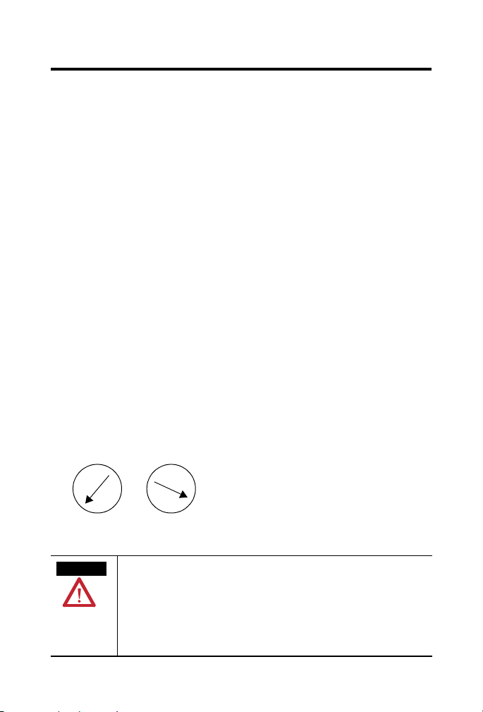
Set MAC ID
Set the MAC ID by using the rotary switches. The MAC ID is set to 63 by
default.
|
8
|
|
6
|
|
2
8
|
4
|
2
|
6
|
|
4
X1X10
WARNING
When you change the Node Address switch settings while
power is on, an electrical arc can occur. This could cause an
explosion in hazardous location installations.
Be sure that power is removed or the area is nonhazardous
before proceeding.
Publication
1791DS-IN002C-EN-P - April 2009
Page 8
8 CompactBlock Guard I/O DeviceNet Safety Modules
Mount the Module
Use these procedures when mounting the module:
• Use horizontal or vertical mounting with a DIN rail that is 35 mm
(1.4 in.) wide for placing the module in the control panel.
• Leave at least 15 mm (0.6 in.) above and below the module for
adequate ventilation and room for wiring.
• Place all other heat sources an appropriate distance from the module
to maintain the specified ambient temperature around the module.
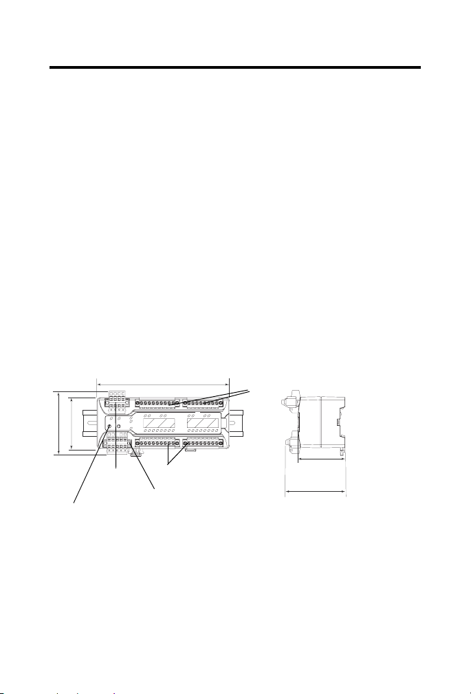
Module Identification and Dimensions
See the figure for module identification and dimensions.
1791DS-IB8XOBV4 module is shown.
1791DS-IB16 module dimensions are identical.
65.5 mm (2.58 in.)
81.017 mm (3.19 in.)
Power
Connector
Node Address Switch
Publication
1791DS-IN002C-EN-P - April 2009
170 mm (6.7 in.)
I/O Connectors (input)
Communication Connector
I/O Connectors
(output)
75.91 mm (2.99 in.)
60.41 mm
(2.38 in.)
44071
Page 9

CompactBlock Guard I/O DeviceNet Safety Modules 9
Wiring the Module
Follow these guidelines when wiring the module:
• Do not route communication, input, or output wiring with conduit
containing high voltage, referring to Industrial Automation Wiring
and Grounding Guidelines, publication 1770-4.1
.
• Wire correctly after confirming the signal names of all terminals.
• Note that stranded wire should be processed with insulation-covered
ferrule (DIN 46228-4 standard compatible-type) at its ends before
using for connection.
• Tighten screws for communication and I/O connectors correctly at
0.25…0.3 N•m (2.21…2.66 lb•in).
Working with Connectors
See the figure that shows connectors.
Power and DeviceNet Connectors
1
2
3
4
Power Configuration
Pin Signal
1 Input +24V DC Power
2 Input Power Common
3
Output +24V DC Power
4
Output Power Common
(1)
NC on 1791DS-IB16 modules.
DeviceNet Configuration
Red
White
Blue
Black
Color Signal
Red V+
White CAN_H
-Drain
44045 44046
Blue CAN-L
Black V-
(1)
(1)
Publication
1791DS-IN002C-EN-P - April 2009
Page 10

10 CompactBlock Guard I/O DeviceNet Safety Modules
Observing Precautions for Safe Use
Read this for a list of precautions for safe use:
• Wire conductors correctly and verify operation of the module before
commissioning the system in which the module is incorporated,
noting that incorrect wiring may lead to loss of safety function.
• Do not apply DC voltages exceeding rated voltages to the module.
• Apply properly specified voltages to the module inputs. Note that
applying inappropriate voltages causes the module to fail to perform
its specified function, which leads to loss of safety functions or
damage to the module.
• Do not use test outputs as safety outputs. Test outputs are not safety
outputs.
• Be sure that qualified personnel confirm installation and conduct test
operations and maintenance after installation of the module.
• Be sure that personnel familiar with machinery where the module is to
be installed conduct and verify installation.
• Do not dismantle, repair, or modify the module. This may lead to loss
of its safety function.
• Use only appropriate components or devices complying with relevant
safety standards corresponding to the required level of safety
categories (safety integrity level). Conformity to requirements of
safety category (safety integrity level) is determined as an entire
system. We recommend you consult a certification body regarding an
assessment of conformity to the required safety level.
• You are responsible for compliance with applicable standards for the
entire system.
• Disconnect the module from the power supply when wiring.
Publication
1791DS-IN002C-EN-P - April 2009
Page 11

CompactBlock Guard I/O DeviceNet Safety Modules 11
ATTENTION
Safety state of the module and its data is defined as the off state.
Serious injury can occur due to breakdown of safety outputs. Do not
connect loads beyond the rated value of the safety outputs.
Serious injury can occur due to loss of required safety functions. Wire
the module properly so that supply voltages or voltages for loads do
not touch the safety outputs accidentally or unintentionally.
As serious injury can occur due to loss of safety functions, use
appropriate devices as shown in the Controlling Devices - Sample
Requirements table.
Controlling Devices - Sample Requirements
Device Requirement Allen-Bradley Bulletin
Emergency
stop switch
Door
interlocking
switch,
limit switch
Safety
sensor
Relay with
forcibly
guided
contacts
Other
devices
Use approved devices with direct opening
mechanism complying with IEC/EN 60947-5-1.
Use approved devices with direct opening
mechanism complying with IEC/EN 60947-5-1
and capable of switching microloads of
24VDC5mA.
Use approved devices complying with the
relevant product standards, regulations, and
rules in the country where used.
Use approved devices with forcibly guided
contacts complying with EN 50205. For
feedback purposes, use devices with contacts
capable of switching microloads of
24VDC5mA.
Evaluate whether devices used are appropriate
to satisfy requirements of safety category
levels.
Safety Components
Bulletin 800F, 800T
Bulletin 440K, 440G, or
440H for interlock
switch, Bulletin 440P or
802T for limit switch
Any Allen-Bradley
Guardmaster product
Bulletin 700S, 100S
Publication
1791DS-IN002C-EN-P - April 2009
Page 12

12 CompactBlock Guard I/O DeviceNet Safety Modules
Interpret the LED Indicators
See the tables for information about how to interpret LED indicators.
24V DC Input Power Indicator
State Status Description Recommended Action
Off No power No power is applied. Apply power to this section.
Solid
green
Solid
yellow
24V DC Output Power Indicator (1791DS-IB8XOBV4 modules only)
State Status Description Recommended Action
Off No power No power is applied. Apply power to this section.
Solid
green
Solid
yellow
Normal
operation
Input power
out of
specification
Normal
operation
Output power
out of
specification
The applied voltage is
within specifications.
The input power is out of
specification.
The applied voltage is
within specifications.
The output power is out
of specification.
None.
Check your configuration,
wiring, and voltages and apply
the changes.
None.
Check your configuration,
wiring, and voltages and
apply the changes.
Module Status Indicator
State Status Description
Off No power or autobauding No power is applied to the
Solid
green
Solid red Unrecoverable fault The module detected an
Publication
Normal operation The module is operating normally.
1791DS-IN002C-EN-P - April 2009
(1)
DeviceNet connector.
unrecoverable fault.
Page 13

CompactBlock Guard I/O DeviceNet Safety Modules 13
Module Status Indicator
(1)
State Status Description
Flashing
green
Module needs commissioning due to
missing, incomplete, or incorrect
Module is unconfigured.
configuration
Flashing
red
Recoverable fault or user-initiated
firmware update in progress
The module has detected a
recoverable fault or user-initiated
firmware update is in progress.
Flashing
red and
Device in self test The module is performing its
power-cycle diagnostic tests.
green
(1)
For recommended action, refer to the user manual that covers these modules.
Network Status Indicator
(1)
State Status Description
Off Module not online or no
The module is not online with the network.
power
Flashing
green
Module online with no
connections in
The module identified the communication rate of
the network but no connections are established.
established state
Solid
green
Module online with
connections in
The module is operating normally.
established state
Publication
1791DS-IN002C-EN-P - April 2009
Page 14

14 CompactBlock Guard I/O DeviceNet Safety Modules
Network Status Indicator
(1)
State Status Description
Flashing
red
One or more I/O
connections in
The module detected a recoverable network fault
or user-initiated firmware update is in progress.
timed-out state or
user-initiated firmware
update in progress
Solid red Critical link failure The module detected an error that prevents it from
communicating on the network.
Flashing
red and
green
Communication faulted
module
The module detected a network access error and is
in communication faulted state. The module
received and accepted an Identity Communication
Faulted Request-long protocol message.
(1)
For recommended action, refer to the user manual that covers these modules.
Safety Input Status Indicator
State Status Description Recommended Action
Off Safety input
off or module
The safety input is off or the
module is being configured.
being
configured
Solid
Safety input onThe safety input is on. None.
yellow
Solid red Fault detected A fault in the external wiring
or input circuit detected.
Flashing
red
Partner fault
detected
A fault in the partner input
circuit of a dual input
configuration detected.
Turn the safety input on or
wait for the module to be
configured.
Check configuration, field
wiring, and devices. If no
problem found, replace
module.
Check the field wiring and
verify your configuration for
the partner circuit. If no
problem found, replace
module.
Publication
1791DS-IN002C-EN-P - April 2009
Page 15

CompactBlock Guard I/O DeviceNet Safety Modules 15
Test Output Status Indicator
State Status Description Recommended Action
Off Test output off
or module being
configured
Solid
yellow
Solid
red
Output is on Output is on. None.
Fault detected A fault in the
The test output
is off or the
module is being
configured.
external wiring
or input circuit
detected.
Turn the test output on or wait for the
module to be configured.
Check field wiring. If no problem found,
replace module. Outputs configured for
muting could indicate undercurrent or
burned-out lamp.
Safety Output Status Indicator (1791DS-IB8XOBV4 modules only)
State Status Description Recommended Action
Off Safety output
off or module
being
configured
Solid
yellow
Solid red Fault detected A fault in the output
Flashing
red
Safety output onThe safety output is on. None.
Partner fault
detected
The safety output is off
or the module is being
configured.
circuit was detected.
Both tags in a dual
channel circuit do not
have the same value.
A fault in the partner of
a dual output circuit
was detected.
Turn the safety output on or wait
for the module to be configured.
Check the circuit wiring and end
device. If no problem found,
replace module.
Make sure logic is driving tag
values to the same state (off or
on).
Check the circuit wiring and end
device of the partner. If no
problem found, replace module.
Publication
1791DS-IN002C-EN-P - April 2009
Page 16

16 CompactBlock Guard I/O DeviceNet Safety Modules
Configuration Lock Indicator
State Status Description Recommended
Off No configuration Invalid configuration data. None
Solid
yellow
Flashing
yellow
(1)
Locked Valid configuration, locked by a
Not locked Valid configuration, owned by a
Not applicable to GuardLogix software.
(1)
Action
None
network configuration tool, such as
RSNetWorx for DeviceNet software.
None
network configuration tool, such as
RSNetWorx for DeviceNet software.
Terminal Positions
See the figure and table for terminal positions. For wiring diagrams, see the
user manual that covers these modules.
18 19 20 21 22 23 23 25 26 27 28 29 30 31 32 33 34
Publication
1 2 3 4 5 6 7 8 9 10 11 12 13 14 15 16 17
1791DS-IN002C-EN-P - April 2009
Page 17

CompactBlock Guard I/O DeviceNet Safety Modules 17
Terminal Positions for Numbers 1…18
Number Terminal for Number Terminal for Number Terminal for
1 Functional Earth 7 Safety Input 3 13 Test Output 5
2 Safety Input 0 8 Test Output 2 14 Safety Input 6
3 Safety Input 1 9 Test Output 3 15 Safety Input 7
4 Test Output 0 10 Safety Input 4 16 Test Output 6
5 Test Output 1 11 Safety Input 5 17 Test Output 7
6 Safety Input 2 12 Test Output 4 18 Functional Earth
Terminal Position for Numbers 19…34
Number Terminal for 1791DS-IB8XOBV4 Terminal for 1791DS-IB16
19
20
21 L-/24V DC common Test Output 8
22 S+/24V DC Test Output 9
23
24
25 L-/24V DC common Test Output 10
26 S+/24V DC Test Output 11
27
28
29 L-/24V DC common Test Output 12
30 S+/24V DC Test Output 13
31
32
33 L-/24V DC common Test Output 14
34 S+/24V DC Test Output 15
(1)
Safety Output 0
Safety Output 1
Safety Output 2
Safety Output 3
Safety Output 4
Safety Output 5
Safety Output 6
Safety Output 7
Safety outputs can be used only as pairs. Safety outputs 0/1, 2/3, 4/5, and 6/7 must be controlled as a pair.
(1)
/Switch +24V DC
(1)/
Switch 24V DC common
(1)
/Switch +24V DC
(1
/Switch 24V DC common
(1)
/Switch +24V DC
(1)
/Switch 24V DC common
(1)
/Switch +24V DC
(1)
/Switch 24V DC common
Safety Input 8
Safety Input 9
Safety Input 10
Safety Input 11
Safety Input 12
Safety Input 13
Safety Input 14
Safety Input 15
Publication
1791DS-IN002C-EN-P - April 2009
Page 18

18 CompactBlock Guard I/O DeviceNet Safety Modules
Specifications
Guard I/O DeviceNet Safety Module - 1791DS-IB8XOBV4, 1791DS-IB16
Attribute Value
Safety Input
Input types Current sinking
Voltage, on-state input, min 11V DC
Current, on-state input, min 3.3 mA
Voltage, off-state input, max 5V DC
Current, off-state, max 1.3 mA
IEC 61131-2 (input type) Type 3
Pulse Test Output
Output type Current sourcing
Pulse test output current 0.7 A
Residual voltage, max 1.2V
Output leakage current, max 0.1 mA
Short circuit protection Yes
Current, max 25 mA
Current, max (to avoid fault when used as a muted lamp
output)
Current, min 5 mA
Safety Output (1791DS-IB8XOBV4 module only)
Output types Current sourcing/current sinking - bipolar pair
Output current rating 2 A max per point
On-state voltage drop ±0.6V
Current, min (at which fault indication is generated when
used as a muted lamp output)
8 A total module @ 40 °C (104 °F)
6 A total module @ 60 °C (140 °F)
Publication
1791DS-IN002C-EN-P - April 2009
Page 19

CompactBlock Guard I/O DeviceNet Safety Modules 19
Guard I/O DeviceNet Safety Module - 1791DS-IB8XOBV4, 1791DS-IB16
Attribute Value
Leakage current
Internal resistance from
±1.0 mA
3.25 kΩ
(1)
PtoM terminal
Short circuit detection Yes (short high and low and cross-circuit fault detect)
Short circuit protection Electronic
Aggregate current of
outputs per module
8 A @ 40 °C
6 A @ 60 °C
Pilot duty rating 2.5 A inrush (1791DS-IB8XOBV4 module only)
Number of outputs 4 dual channel
(1)
Includes the presence of a single P stuck-high or M stuck-low short.
General Specifications
Attribute Value
North American temp code T4A
Enclosure type rating Meets IP20
Communication power
supply voltage
Communication current
consumption
Operating voltage range 19.2…28.8V DC (24V DC, -20…20%)
Isolation voltage 1791DS-I8XOBV4 module - 50V (continuous), basic
11…25V DC (supplied from communication power supply)
85 mA at 24V DC
insulation
Tested at 800V DC for 60 s, between input and output
channels, and between network and I/O channels
1791DS-IB16 module - 50V (continuous), basic insulation
Tested at 800V DC for 60 s, between network and input
channels
Publication
1791DS-IN002C-EN-P - April 2009
Page 20

20 CompactBlock Guard I/O DeviceNet Safety Modules
General Specifications
Attribute Value
Product temperature versus
current derating
8 A
7 A
6 A
-20 °C 40 °C 50 °C 60 °C
Product Temperature Versus Current Derating
(combined current from both input and output supplies)
44199
Wiring category
(1)
2 - on signal ports
2 - on power ports
2 - on communication ports
Wire size
0.34…1.5 mm
2
(22…16 AWG) solid or stranded
copper wire rated at 75 °C (167 °F) or greater 1.2 mm (3/64
in.) insulation max
Weight, approx. 600 g (1.32 lb)
Dimensions (HxWxD),
approx.
(1)
Use this Conductor Category information for planning conductor routing. Refer to Industrial Automation Wiring
and Grounding Guidelines, publication 1770-4.1
Publication
1791DS-IN002C-EN-P - April 2009
81 x 170 x 76 mm (3.1 x 6.7 x 2.9 in.) with terminal block
66 x 170 x 60 mm (2.6 x 6.7 x 2.4 in.) without terminal block
.
Page 21

CompactBlock Guard I/O DeviceNet Safety Modules 21
Environmental Specifications
Attribute Value
Temperature, operating IEC 60068-2-1 (Test Ad, Operating Cold),
IEC 60068-2-2 (Test Bd, Operating Dry Heat),
IEC 60068-2-14 (Test Nb, Operating Thermal Shock):
-20…60 °C (-4…140 °F)
Temperature, storage IEC 60068-2-1 (Test Ab, Unpackaged Nonoperating Cold),
IEC 60068-2-2 (Test Bb, Unpackaged Nonoperating Dry Heat),
IEC 60068-2-14 (Test Na, Unpackaged Nonoperating Thermal
Shock):
-40…85 °C (-40…185 °F)
Relative humidity IEC 60068-2-30 (Test Db, Unpackaged Nonoperating Damp
Heat):
5…95% noncondensing
Vibration IEC 60068-2-6 (Test Fc, Operating):
Shock, operating IEC 60068-2-27 (Test Ea, Unpackaged Shock): 30 g
Shock, nonoperating IEC 60068-2-27 (Test Ea, Unpackaged Shock): 50 g
Emissions CISPR 11: Group 1, Class A
ESD immunity IEC 61000-4-2:
Radiated RF immunity IEC 61000-4-3:
Conducted RF immunity IEC 61000-4-6:
5 g at 10…500 Hz
8 kV contact discharges
15 kV air discharges
10V/m with 1 kHz sine-wave 80%AM from
80…2000 MHz
10V/m with 200 Hz 50% Pulse 100%AM at 900 MHz
10V/m with 200 Hz 50% Pulse 100%AM at 1890 MHz
1V/m with 1 kHz sine-wave 80%AM from 2000…2700 MHz
10V rms with 1 kHz sine-wave 80%AM from
150 kHz…80 MHz
Publication
1791DS-IN002C-EN-P - April 2009
Page 22

22 CompactBlock Guard I/O DeviceNet Safety Modules
Environmental Specifications
Attribute Value
EFT/B immunity IEC 61000-4-4:
±2 kV at 5 kHz on power ports
±2 kV at 5 kHz on signal ports
±2 kV at 5 kHz on communication ports
Surge transient
immunity
Reaction Time
Input reaction time,
max
Output reaction time,
max
IEC 61000-4-5:
±1 kV line-line (DM) and ±2 kV line-earth (CM)
on power ports
±1 kV line-line (DM) and ±2 kV line-earth (CM)
on signal ports
±2 kV line-earth (CM) on communication ports
16.2 ms + set values of ON/OFF delays
6.2 ms + (20 ms) relay response time (1791DS-IB8XOBV4 module
only)
Typical Signal Sequence
Typ. 600 ms
Typ. 700 μs
While safety outputs are in an on state, the signal sequence shown in the figure is
output continuously for fault diagnosis when output pulse testing is enabled.
Confirm response time of device connected to safety outputs so the device does not
malfunction due to off pulse.
Publication
1791DS-IN002C-EN-P - April 2009
44072
Page 23

CompactBlock Guard I/O DeviceNet Safety Modules 23
Certifications
Certification Value
Certifications
(when
product is
marked)
(1)
See the Product Certification link at http://www.ab.com for Declarations of Conformity, Certificates,
and other certification details.
(2)
When used with specified firmware revisions.
c-UL-us UL Listed Industrial Control Equipment, certified for US and
Canada. See UL File E65584.
(1)
UL Listed for Class I, Division 2 Group A,B,C,D Hazardous
Locations, certified for U.S. and Canada. See UL File E194810.
CE European Union 2004/108/EC EMC Directive, compliant with:
EN 61326-1; Meas./Control/Lab., Industrial Requirements
EN 61000-6-2; Industrial Immunity
EN 61000-6-4; Industrial Emissions
EN 61131-2; Programmable Controllers
(Clause 8, Zone A & B)
C-Tick Australian Radiocommunications Act, compliant with:
AS/NZS CISPR 11; Industrial Emissions
ODVA ODVA conformance tested to DeviceNet specifications
TÜV TÜV Certified for Functional Safety up to and including
Category 4 and SIL 3
(2)
Publication
1791DS-IN002C-EN-P - April 2009
Page 24

Additional Resources
For safe and correct use of the product, read these publications:
• DeviceNet Modules in Logix5000 Control Systems User Manual,
publication DNET-UM004
• Guard I/O DeviceNet Safety Modules User Manual, publication
1791DS-UM001
You can view or download publications at
http://literature.rockwellautomation.com
documentation, contact your local Rockwell Automation distributor or sales
representative.
. To order paper copies of technical
Allen-Bradley, CompactBlock Guard I/O, GuardLogix, Logix5000, Rockwell Automation, and RSNetWorx for
DeviceNet are trademarks of Rockwell Automation, Inc.
Trademarks not belonging to Rockwell Automation are property of their respective companies.
Publication 1791DS-IN002C-EN-P - April 2009 PN-44442
Supersedes Publication 1791DS-IN002B-EN-P - January 2007 Copyright © 2009 Rockwell Automation, Inc. All rights reserved. Printed in the U.S.A.
 Loading...