

Page 1
Installation Instructions
Selectable
Contact Output Module
(Catalog Number 1771–OWN)
Contents
Important User
Information
Use this document as a guide when installing the catalog number
1771-OWN series B contact output module.
To See page
Important User Information 1
Preinstallation Considerations 4
Power Supply Requirements 4
Key the Backplane Connector 5
Set the Relay Output Jumpers 5
Install the Module and Field Wiring Arm 7
Connect Wiring to the Field Wiring Arm 8
For this reference information See page
Interpreting the Status Indicators 11
Hazardous Location Approval 12
Specifications 13
Because of the variety of uses for the products described in this
publication, those responsible for the application and use of these
products must satisfy themselves that all necessary steps have been
taken to assure that each application and use meets all performance
and safety requirements, including any applicable laws, regulations,
codes and standards. In no event will Rockwell Automation be
responsible or liable for indirect or consequential damage resulting
from the use or application of these products.
Any illustrations, charts, sample programs, and layout examples
shown in this publication are intended solely for purposes of
example. Since there are many variables and requirements associated
with any particular installation, Rockwell Automation does not
assume responsibility or liability (to include intellectual property
liability) for actual use based upon the examples shown in this
publication.
Allen–Bradley publication SGI–1.1, Safety Guidelines for
Application, Installation, and Maintenance of Solid–State Control
(available from your local Rockwell Automation office), describes
some important differences between solid–state equipment and
electromechanical devices that should be taken into consideration
when applying products such as those described in this publication.
Publication 1771-IN037B-EN-P - July 2002
Page 2
Selectable Contact Output Module2
Reproduction of the contents of this copyrighted publication, in
whole or part, without written permission of Rockwell Automation,
is prohibited.
Throughout this publication, notes may be used to make you aware
of safety considerations. The following annotations and their
accompanying statements help you to identify a potential hazard,
avoid a potential hazard, and recognize the consequences of a
potential hazard.
WARNING
!
ATTENTION
!
IMPORTANT
Identifies information about practices or
circumstances that can cause an explosion in a
hazardous environment, which may lead to
personal injury or death, property damage, or
economic loss.
Identifies information about practices or
circumstances that may lead to personal injury or
death, property damage, or economic loss.
Identifies information that is critical for
successful application and understanding of the
product.
Publication 1771-IN037B-EN-P - July 2002
Page 3

Selectable Contact Output Module 3
ATTENTION
!
Environment and Enclosure
This equipment is intended for use in a Pollution
Degree 2 industrial environment, in overvoltage
Category II applications (as defined in IEC
publication 60664–1), at altitudes up to 2000
meters without derating.
This equipment is considered Group 1, Class A
industrial equipment according to IEC/CISPR
Publication 11. Without appropriate precautions,
there may be potential difficulties ensuring
electromagnetic compatibility in other
environments due to conducted as well as radiated
disturbance.
This equipment is supplied as “open type”
equipment. It must be mounted within an
enclosure that is suitably designed for those
specific environmental conditions that will be
present, and appropriately designed to prevent
personal injury resulting from accessibility to live
parts. The interior of the enclosure must be
accessible only by the use of a tool. Subsequent
sections of this publication may contain additional
information regarding specific enclosure type
ratings that are required to comply with certain
product safety certifications.
See NEMA Standards publication 250 and IEC
publication 60529, as applicable, for explanations
of the degrees of protection provided by different
types of enclosures. Also, see the appropriate
sections in this publication, as well as the
Allen–Bradley publication 1770–4.1, (“Industrial
Automation Wiring and Grounding Guidelines”),
for additional installation requirements pertaining
to this equipment.
Publication 1771-IN037B-EN-P - July 2002
Page 4

Selectable Contact Output Module4
PreĆinstallation
Considerations
ATTENTION
!
Preventing Electrostatic Discharge
This equipment is sensitive to electrostatic
discharge, which can cause internal damage and
affect normal operation. Follow these guidelines
when you handle this equipment:
• Touch a grounded object to discharge potential
static.
• Wear an approved grounding wriststrap.
• Do not touch connectors or pins on component
boards.
• Do not touch circuit components inside the
equipment.
• If available, use a static–safe workstation.
• When not in use, keep modules in appropriate
static–safe packaging.
This module must be used in a 1771-A1B through -A4B or later I/O
chassis.This module does not contain surge limiting circuitry. Use
this module for switching resistive loads only. It is not
recommended for inductive or capacitive loads.
The outputs are arranged in 4 groups of 8, each group with its own
common. The module can simultaneously switch all 32 outputs to
separate loads, with a maximum of 12A per module. Each output
can conduct a maximum load of 1.0A continuously at 30W at 45
and 15W at 60
should have a power factor (PF) of 1.0.
o
C maximum. Ac loads switched by the modules
o
C,
Power Supply
Requirements
Maximum interconnect cable length for this module is 1000 ft.
(304.8 meters).
The controller or I/O chassis power supply, connected through the
backplane of the I/O chassis, powers the logic circuitry of the contact
output modules. This supply also provides the necessary power to
energize the coils of the module relays. The maximum current drawn
from this supply when all coils are energized is 2.5A. Nominal
backplane current is 1.8A.
Publication 1771-IN037B-EN-P - July 2002
Page 5
Selectable Contact Output Module 5
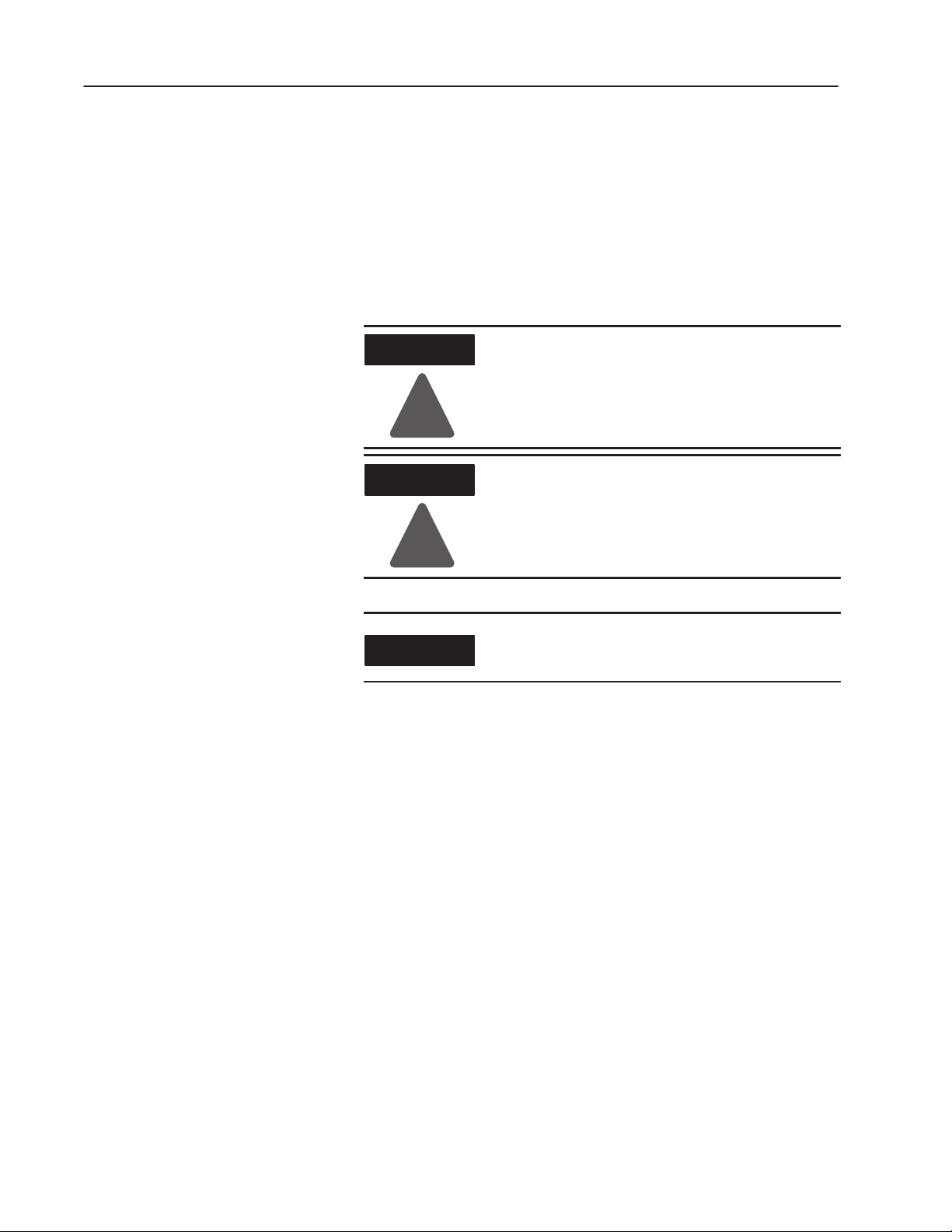
Key the Backplane
Connector
Place your module in any slot in the chassis
except the leftmost slot which is reserved
for processors or adapters.
ATTENTION
Observe the following
precautions when inserting or
removing keys:
!
• insert or remove keys with
your fingers
• make sure that key placement
is correct
Incorrect keying or the use of a
tool can result in damage to the
backplane connector and
possible system faults.
Setting the Relay Output
Jumpers
Position the keying bands in the backplane connectors to correspond to
the key slots on the module.
I/O chassis
You can change the position of these bands if
subsequent system design and rewiring makes
insertion of a different type of module necessary.
Place the keying bands:
- between 6 and 8
- between 16 and 18
Upper
Connector
11022ĆI
When the output image table bit at the address corresponding to any
output is energized (set to 1), the corresponding relay contact is
closed or opened, respective to the jumper setting.
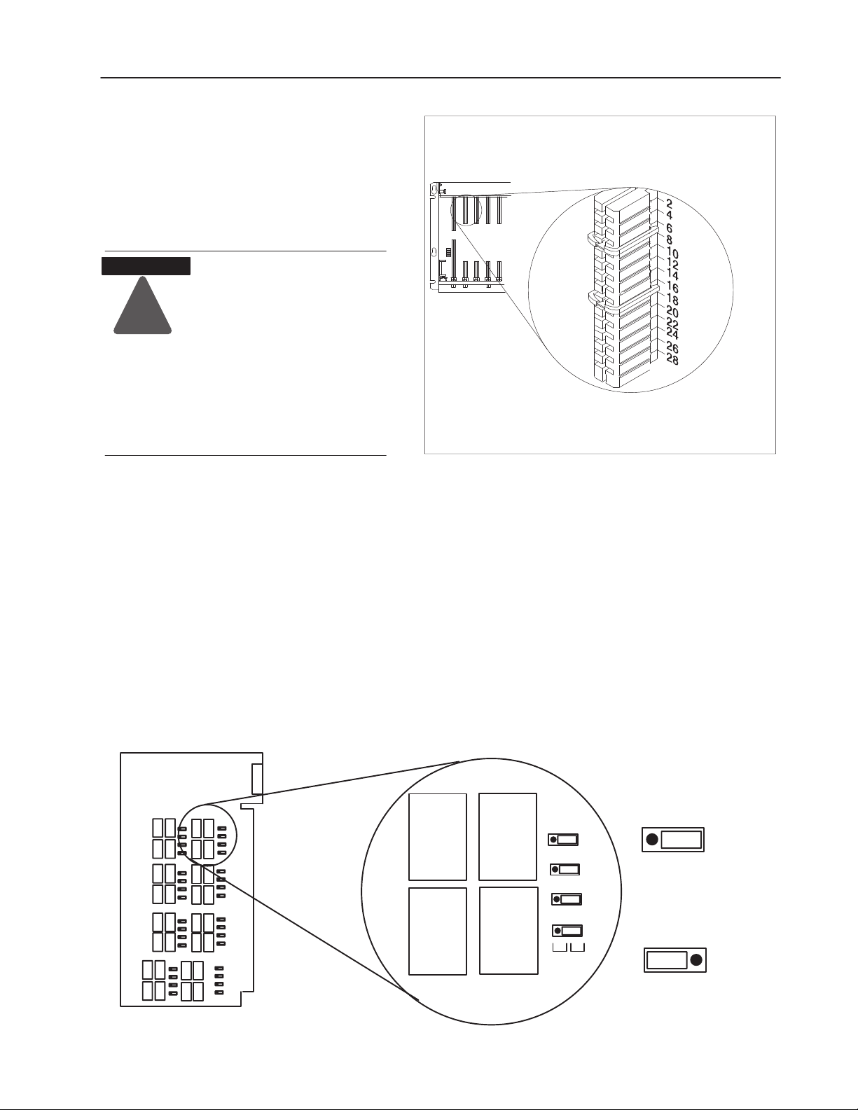
Printed Circuit Board
All outputs are individually selectable for either normally-open or
normally-closed operation. They are pre-set for normally-open
operation at the factory. To reset any jumper, proceed as follows:
1. Remove the 4 screws from the side cover and separate the circuit
board from the 2 covers.
2. Move the jumper to the desired position. Jumpers are identified
by jumper number and use (N.O. or N.C.). Refer to Table A for
jumper and terminal identifications.
RY9
L-00
RY10
L-02
L-04
RY2RY1
L-06
N.O.N.C.
10538ĆI
N.O.N.C.
Normally Open
N.O.N.C.
Normally Closed
Publication 1771-IN037B-EN-P - July 2002
Page 6

Selectable Contact Output Module6
3. Reinstall the circuit board in the module and replace the cover.
Table A
Jumper Identification for Individual Outputs
Terminal
Number
Function
1 Common 0 21 Common 2
2 Output 00 LĆ00 22 Output 00 HĆ00
3 Output 01 LĆ01 23 Output 01 HĆ01
4 Output 02 LĆ02 24 Output 02 HĆ02
5 Output 03 LĆ03 25 Output 03 HĆ03
6 Output 04 LĆ04 26 Output 04 HĆ04
7 Output 05 LĆ05 27 Output 05 HĆ05
8 Output 06 LĆ06 28 Output 06 HĆ06
9 Output 07 LĆ07 29 Output 07 HĆ07
10 Not used 30 Not used
11 Common 1 31 Common 3
12 Output 10 LĆ10 32 Output 10 HĆ10
13 Output 11 LĆ11 33 Output 11 HĆ11
14 Output 12 LĆ12 34 Output 12 HĆ12
Jumper
Number
Terminal
Number
Function
Jumper
Number
15 Output 13 LĆ13 35 Output 13 HĆ13
16 Output 14 LĆ14 36 Output 14 HĆ14
17 Output 15 LĆ15 37 Output 15 HĆ15
18 Output 16 LĆ16 38 Output 16 HĆ16
19 Output 17 LĆ17 39 Output 17 HĆ17
20 Not used 40 Not used
If using multiple power supplies, do not exceed the specified isolation voltage.
Publication 1771-IN037B-EN-P - July 2002
Page 7

Selectable Contact Output Module 7
Install the Module and
ATTENTION
Field Wiring Arm
!
WARNING
!
Place the module in the card guides on the top and bottom of the chassis
1
that guide the module into position.
Important: Apply firm even pressure on the module to seat it into its
backplane connector.
1771ĆA1B, ĆA2B, ĆA3B, ĆA4B I/O chassis
Remove power from the 1771 I/O chassis
backplane before you install the module. Failure
to remove power from the backplane could cause:
• module damage
• degradation of performance
• injury or equipment damage due to possible
unexpected operation
When you insert or remove the module with field
power applied, or connect or disconnect the field
wiring arm with field side power applied, an
electrical arc can occur. This could cause an
explosion in hazardous location installations.Be
sure that power is removed or the area is
nonhazardous before proceeding.
1771ĆA1B, ĆA2B, ĆA4B Series B I/O chassis
Snap the chassis latch over the
top of the module to secure it.
Attach the wiring arm (1771ĆWN) to the horizontal bar at the
2
bottom of the I/O chassis.
The wiring arm pivots upward and connects with the
module so you can install or remove the module without
disconnecting the wires.
Swing the chassis locking bar
down into place to secure the
modules. Make sure the locking
pins engage.
1771ĆWN
remove
horizontal bar
The 1771–OWN module is a modular component of the 1771 I/O
system requiring a properly installed system chassis. Refer to
publication 1771–IN075 for detailed information on acceptable
chassis, proper installation and grounding requirements. Limit the
maximum adjacent slot power dissipation to 10W maximum.
install
Publication 1771-IN037B-EN-P - July 2002
Page 8

Selectable Contact Output Module8
Connect Wiring to the
Module
Make wiring connections to the module through the field wiring arm
(cat. no. 1771-WN). The arm pivots on the I/O chassis to connect
with terminals on the front of the module and acts as a terminal strip.
The wiring arm allows the module to be removed from the chassis
without disconnecting wiring.
WARNING
!
ATTENTION
!
When you connect or disconnect the field wiring
arm with field power applied, or remove the
module while backplane power is on, an electrical
arc can occur. This could cause an explosion in
hazardous location installations.
Be sure that power is removed or the area is
nonhazardous before proceeding.
Remove power from the 1771 I/O chassis
backplane and field wiring arm before removing
or installing an I/O module.
• Failure to remove power from the backplane or
wiring arm could cause module damage,
degradation of performance, or injury.
• Failure to remove power from the backplane
could cause injury or equipment damage due to
possible unexpected operation.
1. Make certain all power is removed from the module before
making wiring connections.
2. Swing the wiring arm up into position on the front of the module.
The locking tab on the module will secure it into place.
Publication 1771-IN037B-EN-P - July 2002
Page 9

Selectable Contact Output Module 9
T
3. Make your connections to the field wiring arm as shown in the
connection diagram. (Use the label on the front of the wiring arm
to identify your wiring.)
The field wiring arm terminal identification
IMPORTAN
number is not the same as the number of the bit
which controls that output.
Connection Diagram for the 1771-OWN DC Output Module
Output 0
Output 2
Output 4
Output 6
Not used
Output 10
Output 12
Output 14
Output 16
Not used
Output 0
Output 2
Output 4
Output 6
Not used
Output 10
Output 12
Output 14
Output 16
Not used
Note: Terminals on the left are
even numbered, and terminals
on the right are odd numbered.
(Actual wiring runs in this direction.)
If multiple power supplies are used, do not exceed the specified isolation voltage.
2
4
6
8
10
12
14
16
18
20
22
24
26
28
30
32
34
36
38
40
Note: Contacts shown in N.O.
configuration for simplicity.
Common 0
Output 1
Output 3
Output 5
Output 7
Common 1
Output 11
Output 13
Output 15
Output 17
Common 2
Output 1
Output 3
Output 5
Output 7
Common 3
Output 11
Output 13
Output 15
Output 17
10539ĆI
ATTENTION
Miswiring or shorting the output terminals will
cause permanent damage to this module.
!
ATTENTION
Observe proper polarity with dc power
connections. Reverse polarity, or application of ac
voltage could damage the module.
!
Publication 1771-IN037B-EN-P - July 2002
Page 10

Selectable Contact Output Module10
ATTENTION
!
You can use the 1771-OWN output module to drive an input of a
120V ac input module (1771-IA, -IA2, -IAD) to indicate status of
turning on a motor starter as shown below, for example, but you
must connect a 15K, 2W resistor between the output and L2
(common). Inputs configured with the output module are not isolated
from each other.
Driving an Input Module with a 1771-OWN Output Module
Selectable Contact Output Module
(Cat. No. 1771ĆOWN)
Output 0
Output 2
Output 4
Output 6
Not used
Output 10
Output 12
Output 14
Output 16
Not used
Output 0
Output 2
Output 4
Output 6
Not used
Output 10
Output 12
Output 14
Output 16
Not used
Common 0
Output 1
Output 3
Output 5
Output 7
Common 1
Output 11
Output 13
Output 15
Output 17
Common 2
Output 1
Output 3
Output 5
Output 7
Common 3
Output 11
Output 13
Output 15
Output 17
Do not attempt to increase load current or wattage
capability beyond the rating by connecting two or
more outputs in parallel. The slightest variation in
output relay switching time may cause one set of
contacts to switch the total load current.
120V AC Input Module
(Cat. No. 1771ĆIAD)
L1
Input 00
Input 01
Input 02
Input 03
Input 04
Input 05
Input 06
Input 07
Input 10
Input 11
Input 12
Input 13
Input 14
Input 15
Input 16
Input 17
ac High
L2
ac Low
15K ohm, 2W
resistor
1
2
3
4
5
6
7
8
9
10
11
12
13
14
15
16
17
18
19
20
21
If multiple power supplies are used, do not exceed the specified isolation voltage.
Publication 1771-IN037B-EN-P - July 2002
10540ĆI
Page 11

Selectable Contact Output Module 11
Interpreting the Status
Indicators
The module has 32 status indicators on the module front plate. These
represent the control status of the outputs. Each indicator is lit when
its corresponding output is energized. An additional indicator is
provided to indicate a blown fuse condition.
10
10
00
00
01
11
01
11
12
12
02
02
03
13
03
13
04
14
04
14
05
15
05
15
16
16
06
06
17
17
07
07
Status Indicators (red)
10541ĆI
Publication 1771-IN037B-EN-P - July 2002
Page 12

Selectable Contact Output Module12
The following information applies when operating this equipment in
hazardous locations:
Products marked CL I, DIV 2, GP A, B, C, D" are suitable for use in Class I Division 2 Groups A, B, C,
and D Hazardous Locations and nonhazardous locations only. Each product is supplied with markings on
the rating nameplate indicating the hazardous location temperature code. When combining products
within a system, the most adverse temperature code (lowest T" number) may be used to help determine
the overall temperature code of the system. Combinations of equipment in your system are subject to
investigation by the local Authority Having Jurisdiction at the time of installation.
WARNING
EXPLOSION HAZARD -
• Do not disconnect equipment unless power has been removed or the
area is known to be nonhazardous.
• Do not disconnect connections to this equipment unless power has
been removed or the area is known to be nonhazardous. Secure any
!
external connections that mate to this equipment by using screws,
sliding latches, threaded connectors, or other means provided with
this product.
• Substitution of components may impair suitability for Class I, Division
2.
• If this product contains batteries, they must only be changed in an
area known to be nonhazardous.
Informations sur l'utilisation de cet équipement en environnements dangereux:
Les produits marqués CL I, DIV 2, GP A, B, C, D ne conviennent que une utilisation en environnements
de Classe I Division 2 Groupes A, B, C, D dangereux et non dangereux. Chaque produit est livré avec
des marquages sur sa plaque d'identification qui indiquent le code de température pour les
environnements dangereux. Lorsque plusieurs produits sont combinés dans un systéme, le code de
température le plus défavorable (code de température le plus faible) peut eatre utilisé pour déterminer le
code de température global du systéme. Les combinaisons d'equipements dans le systéme sont sujettes
à inspection par les autorités locales qualifiées au moment de l'installation.
AVERTISSEMENT
RISQUE D'EXPLOSION -
• Couper le courant ou s'assurer que l'environnement est classé non
dangereux avant de débrancher l'équipement.
• Couper le courant ou s'assurer que l'environnement est classé non
dangereux avant de débrancher les connecteurs. Fixer tous les
!
connecteurs externes reliés à cet équipement à l'aide de vis, loquets
coulissants, connecteurs filetés ou autres moyens fournis avec ce
produit.
• La substitution de composants peut rendre cet équipement inadapté
à une utilisation en environnement de Classe 1,
Division 2.
• S'assurer que l'environnement est classé non dangereux avant de
changer les piles.
Publication 1771-IN037B-EN-P - July 2002
Page 13

Selectable Contact Output Module 13
Specifications
Outputs per module 32 (4 groups of 8)
Module Location 1771ĆA1B thru ĆA4B or later I/O Chassis, 1771ĆAM, ĆAM1 I/O
Chassis
Voltage Rating 24 Ć 138V ac rms; 24 Ć 125V dc
Current Rating
Maximum Surge Current 1A (max) per output (at rated power)
1
Max. per channel
Max. per module
Max. per group
1A continuous (derate linearly 0.033A/oC above 45oC)
12A (derate linearly 0.4A/
4A (derate linearly 0.133A/
o
C above 45oC)
o
C above 45oC)
2
Output Contact Power Rating 30W per output (resistive) at 45oC, 15W at 60oC
Minimum Contact Load 10mA
Operate/Release Time 5ms (+1ms) typical
Bounce Time 1ms (max)
Switching Frequency 10Hz (max)
Power Dissipation All relays off: 15mW; All relays on: 13.7W (max.)
Thermal Dissipation All relays off: 0.05 BTU/hr; All relays on: 46.7 BTU/hr (max.)
Backplane Current 2.5A maximum; 1.8A nominal
Isolation Voltage Tested to withstand 1000V for 60s.
Interconnect Cable Length 1000 ft. (304.8 meters)
Conductors Wire Size
14-22 AWG (2.5-0.5mm2) (max) stranded copper rated at 60oCor
greater
3/64 inch (1.2mm) insulation (max)
Category
Environmental Conditions
Operating
Temperature
3
2
IEC 60068-2-1 (Test Ad, Operating Cold)
IEC 60068-2-2 (Test Bd, Operating Dry Heat)
IEC 60068-2-14 (Test Nb, Operating Thermal Shock)
32 to 140°F(0
o
to 60oC)
Storage Temperature IEC 60068-2-1 (Test Ab, Unpackaged, Nonoperating Cold)
IEC 60068-2-2 (Test Bb, Unpackaged, Nonoperating Dry Heat)
IEC 60068-2-14 (Test Na, Unpackaged, Nonoperating Thermal
Shock)
-40 to 185°F (-40 to 85
o
C)
Relative Humidity IEC 60068-2-30 (Test Db, Unpackaged, Nonoperating Damp Heat)
5 to 95%, noncondensing
Shock
Operating
Nonoperating
IEC 60068-2-27 (Test Ea, Unpackaged Shock)
30g
50g
Vibration IEC 60068-2-6 (Test Fc, Operating)
2g @ 10-500Hz
ESD Immunity IEC 61000-4-2
4kV contact discharges
Radiated RF Immunity IEC 61000-4-3
10V/m with 1kHz sine-wave 80% AM from 30MHz to 1000MHz
10V/m with 200Hz 50% pulse 100% AM at 900MHz
EFT/B Immunity IEC 61000-4-4
1kV @ 5kHz on signal ports
+
Surge Transient Immunity IEC 61000-4-5
1kV line-line (DM) and +2kV line-earth (CM) on signal ports
+
Specifications continued on next page.
Publication 1771-IN037B-EN-P - July 2002
Page 14

Selectable Contact Output Module14
Conducted RF Immunity IEC 61000-4-6
10V rms with 1kHz sine wave 80% AM from 150kHz to 30MHz
Emissions CISPR 11
Group 1, Class A (with appropriate enclosure)
Enclosure Type Rating None (open-style)
Keying Between 6 and 8
Between 16 and 18
Field Wiring Arm 1771ĆWN
Wiring Arm Screw Torque 9 pound-inches (1.0Nm)
Certifications
(when product is marked)
UL UL Listed Industrial Control Equipment
CSA CSA Certified Process Control Equipment
CSA CSA Certified Process Control Equipment for Class I,
Division 2 Group A, B, C, D Hazardous Locations
4
CE
European Union 89/336/EEC EMC Directive,
compliant with:
EN 61000-6-4, Industrial Emissions
EN 50082-2, Industrial Immunity
EN 61326, Meas./Control/Lab., Industrial Requirements
EN 61000-6-2, Industrial Immunity
European Union 73/23/EEC LVD Directive,
compliant with:
EN 61131-2, Programmable Controllers
4
Australian Radiocommunications Act, compliant with:
C-Tick
AS/NZS 2064, Industrial Emissions
1
Spikes, peaks and surgesmust be within the power rating. Resistive loads only. ac and dc power = 30W max.
2
Surge limiting circuitry is not provided in the module. For reliable operation, the user must ensure that surges do not exceed either the voltage
or current rating of the module.
3
You use this conductor category information for planning conductor routing as described in publication 1770Ć4.1, Industrial
Automation Wiring and Grounding Guidelines.
4
See the Product Certification link at www.ab.com for Declarations of Conformity, Certificates and other certification details
Publication 1771-IN037B-EN-P - July 2002
Page 15

Selectable Contact Output Module 15
Publication 1771-IN037B-EN-P - July 2002
Page 16

Selectable Contact Output Module16
Publication 1771-IN037B-EN-P - July 2002
Supersedes Publication 1771-5.37 - October 1995
Publication 1771-IN037B-EN-P - July 2002
Copyright 2002 Rockwell Automation, Inc. Printed in USA
PN957678-79
 Loading...